

Page 1

Customer Care Solutions
NMM-3 Series Transceivers
3 - Service Software
Issue 1 (11/2003) Copyright 2003 Nokia Corporation Page 3-1
Company Confidential
Page 2

NMM-3 Company Confidential
3 - Service Software CCS Technical Documentation
Table of Contents
Description
Page No.
Service Software .......................................................................................... 5
Phoenix ................................................................................................... 5
Supported Operating Systems ................................................... 5
Hardware requirements for using Phoenix ............................ 5
Introduction ................................................................................... 5
Installing Phoenix ................................................................. 5
Uninstalling Phoenix ............................................................ 6
Data Packages ........................................................................ 6
Starting a session ......................................................................... 6
Concepts .................................................................................. 6
Selecting a product ............................................................... 7
Selecting a connection ........................................................ 7
Phoenix environment ........................................................... 7
Using components ................................................................ 7
Using profiles .......................................................................... 7
SW update flashing setup .................................................................. 8
FPS-8 Flash setup ......................................................................... 8
POS Flash concept ........................................................................ 9
USB Flash concept 1 .................................................................... 10
USB Flash concept 2 .................................................................... 11
NMM-3 Phoenix installation instructions ............................. 11
FPS-8 to PC connection Setup instructions .......................... 12
FPS-8 activation ........................................................................... 12
Checking application SW version inside FPS-8 .................... 12
Reprogramming NMM-3 ................................................................... 14
Updating software ........................................................................ 14
Service Tool Concepts for Calibration ............................................ 15
Calibration Set-up using MJS-84 ............................................ 16
Calibration Set-up using JBV-1 ................................................ 17
Energy Management Calibration ..................................................... 18
Automatic Calibration ................................................................. 18
Connections ................................................................................... 18
Phoenix Setup ................................................................................ 18
Calibration ...................................................................................... 19
Limits for Energy Management Calibration ................... 20
GSM Tuning ........................................................................................... 20
General remarks on GSM RF Tuning ........................................ 20
Introduction ................................................................................... 20
Page 3-2 Copyright 2003 Nokia Corporation Issue 1 (11/2003)
Company Confidential
Page 3

Company Confidential NMM-3
CCS Technical Documentation 3 - Service Software
Description
Page No.
Receiver Tunings ........................................................................... 20
RX Channel Select Filter Calibration ............................... 20
RX Calibration ....................................................................... 21
RX Band Filter Response Compensation ........................ 24
RX DtoS Balance Calibration ............................................. 28
Transmitter Tunings ..................................................................... 29
TX I/Q Tuning .......................................................................... 29
TX Power Level Tuning .......................................................... 32
WCDMA Tuning .................................................................................... 36
WCDMA RF Tunings ..................................................................... 36
WCDMA RF Channel Filter Calibration ............................ 36
WCDMA Temperature Sensor Calibration ..................... 37
WCDMA RX AGC Alignment ............................................... 37
WCDMA RX Band Response Calibration ......................... 39
WCDMA TX Bias Current Tuning ....................................... 40
WCDMA TX AGC Alignment ............................................... 41
WCDMA TX Power Detector Calibration ......................... 43
WCDMA TX Band Response Calibration .......................... 44
WCDMA RF Testing Using Local Mode ............................ 46
WCDMA TX Control .............................................................. 46
WCDMA RX Control .............................................................. 47
Issue 1 (11/2003) Copyright 2003 Nokia Corporation Page 3-3
Company Confidential
Page 4

NMM-3 Company Confidential
3 - Service Software CCS Technical Documentation
This page has been deliberately left blank
Page 3-4 Copyright 2003 Nokia Corporation Issue 1 (11/2003)
Company Confidential
Page 5

Company Confidential NMM-3
CCS Technical Documentation 3 - Service Software
Service Software
Phoenix
Phoenix is the new generation Service Software. It has been designed to meet the challenges in servicing modern cellular phone technology.
The Phoenix program has been built using component architecture. This means that the
actual program is small and most of the program’s functionality is divided into dynamically loaded modules (DLLs).
Supported Operating Systems
Windows 98, 2000, ME and NT 4.0 (SP4).
Hardware requirements for using Phoenix
Minimum:
Processor 233 MHz, RAM memory 64 MB, Disk space 50-100 MB.
Recommended for Windows 2000:
Processor 700 MHz, RAM memory 512 MB, Disk space 50-100 MB.
Introduction
This section briefly describes how to install the Phoenix software and includes some
basic information on how to use the program. For more detailed information, please refer
to Phoenix’s Help -files. Each feature in Phoenix has its own Help function, which can
be activated while running the program.
Press the F1 key or the feature’s Help-button to activate a Help -file.
Installing Phoenix
1. Download the latest release. Please contact your regional After Market Services point
for information on where to download the latest release.
Download and read the release notes, which have useful information on the software
version you are using.
2. Download the latest data packages for the products you will be using.
3. Before you start installing the program, check that
- the dongle is attached to parallel port. Contact your supervisor in order to obtain a
suitable dongle.
- you have administrator rights (Windows 2000 or NT only). This is required in order
to be able to install Phoenix.
4. Install Phoenix by executing the Phoenix installation package and follow the instructions on the screen.
Initially the setup files are extracted into the file system.
Note: If the setup files are already extracted (left in the file system from previous instal-
Issue 1 (11/2003) Copyright 2003 Nokia Corporation Page 3-5
Company Confidential
Page 6

NMM-3 Company Confidential
3 - Service Software CCS Technical Documentation
lation) “Overwrite Protection” dialog appears. Always click "Yes to All" to overwrite the
existing setup files.
5. The installation checks that the latest supported dongle driver version is installed. The
dongle driver is installed if there is no previous installation of the dongle driver or if the
installed dongle driver is older than the latest supported version.
Note: If the dongle driver is installed during installation, you need to reboot your PC and
restart the installation after reboot.
Program files are stored under ” C:\Program Files\Nokia\Phoenix” (default).
6. Install the data package by executing the installation package and follow the instructions on the screen.
The data packages will create product specific directories under the installation directory.
Data files are stored under ” C:\Program Files\Nokia\Phoenix” (default).
Uninstalling Phoenix
If you need to remove Phoenix Service Software from your computer:
1. Make sure that the dongle is attached (unregistration).
2. Go to the Control Panel and select Add/Remove Programs.
3. Select Phoenix for uninstallation and click Add/Remove.
4. Click OK to remove the application
You may have to reboot your PC after uninstallation.
Note: If you have different product packages installed, the components are uninstalled only if
they are not included in other product packages.
Data Packages
Data Packages (DP) is a name for a helpful feature in the Phoenix software. This type of
feature provides a flexible way of distributing and installing Phoenix and its data files.
All product-specific data is separated from the program code and installed separately.
This means that the installation is performed in at least two steps.
Each product will have its own Data Package (DP). The FPS-8 flashing equipment also has
its own package.
Starting a session
Concepts
In the Phoenix context, Product means the cellular phone attached to a PC. More specifically, it is a particular type of phone.
Page 3-6 Copyright 2003 Nokia Corporation Issue 1 (11/2003)
Company Confidential
Page 7

Company Confidential NMM-3
CCS Technical Documentation 3 - Service Software
Connection means the type of cable used to attach the phone to the port to which the
other end of the cable is attached.
Selecting a product
Many of Phoenix’s features are product-specific. It is, therefore, mandatory to choose the
product you will be working on at the beginning of the session.
Select the menu item File - Choose Product. You will be presented with a list of available
products.
After the product selection, you will see an additional menu item on the main menu. If
you take a look at the available menu items, you will see that their number has
increased.
Selecting a connection
The connection defines the cable and the communications port that will be used when
connecting to the phone.
1. Active connections are listed in the toolbar’s Connection pull-down menu. You should
make sure that the connection is correct before using the software. Change it, if necessary.
In case the connection is the wrong, you need to create a new one.
2. Select Settings from the pull-down menu .
3. Select Add in the Connection List Dialog and in fill the relevant fields in the Connec-
tion setup dialog.
Phoenix environment
You can configure the program’s main toolbar and the product or tool -specific options
to your liking.
You can control which toolbars are visible by selecting View and Toolbars from the pulldown menu. The visible toolbars are marked with a check.
The rest of the options are product or tool -specific. The tool-specific options are set
using the associated toolbar.
Using components
When working with Phoenix, each task generally has its own component that will perform the task. The first thing, therefore, is to open the desired component.
Opening a component means that you open a tool window within Phoenix. When this
window is opened, Phoenix also opens a toolbar for it and adds component-specific
menu items in the View menu.
Using profiles
A Profile is a useful feature in the software. Product, connection and currently open
Issue 1 (11/2003) Copyright 2003 Nokia Corporation Page 3-7
Company Confidential
Page 8
NMM-3 Company Confidential
3 - Service Software CCS Technical Documentation
components can be stored into a permanent storage (a disk file called profile, *.nmp) for
later retrieval.
Opening and saving profiles is done via menu commands found in the File menu. Select
Open Profile and Save Profile.
Since profiles are stored into a disk file with the user-defined name, there can be multiple profiles for different repeated tasks.
SW update flashing setup
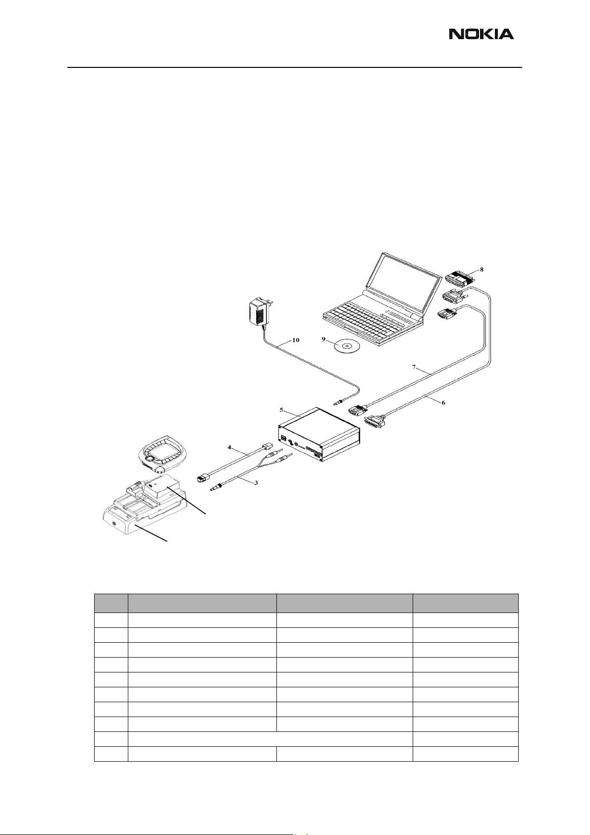
FPS-8 Flash setup
2
1
The following equipment is required for 7600 (NMM-3) AMS SW update, when connecting NMM-3 to PC with FPS-8:
Item Description Type Code
1 Docking station JBV-1 0770298
2 Docking station adapter MJF-29 (used with JBV-1) 0770592
3 DC Power cable PCS-1 0730012
4 Modular cable XCS-4 0730178
5 Flash prommer box sales pack FPS-8 0080321
6 Printer cable ~ (supplied with FPS-8) 0730029
7 RS232 (D9 – D9) cable AXS-4 , incl in FPS-8 sales pack 0730090
8 Software protection key (Dongle) PKD-1 0750018
Service SW (downloadable from PWS) xxxxxxxx
10 AC Charger, ACF-8, incl in FPS-8 sale s pack 0680032
Page 3-8 Copyright 2003 Nokia Corporation Issue 1 (11/2003)
Company Confidential
Page 9
Company Confidential NMM-3
CCS Technical Documentation 3 - Service Software
Note: When flashing the NMM-3 there must be two additional SRAM cards (SF12: code
00803346) assembled inside the FPS-8
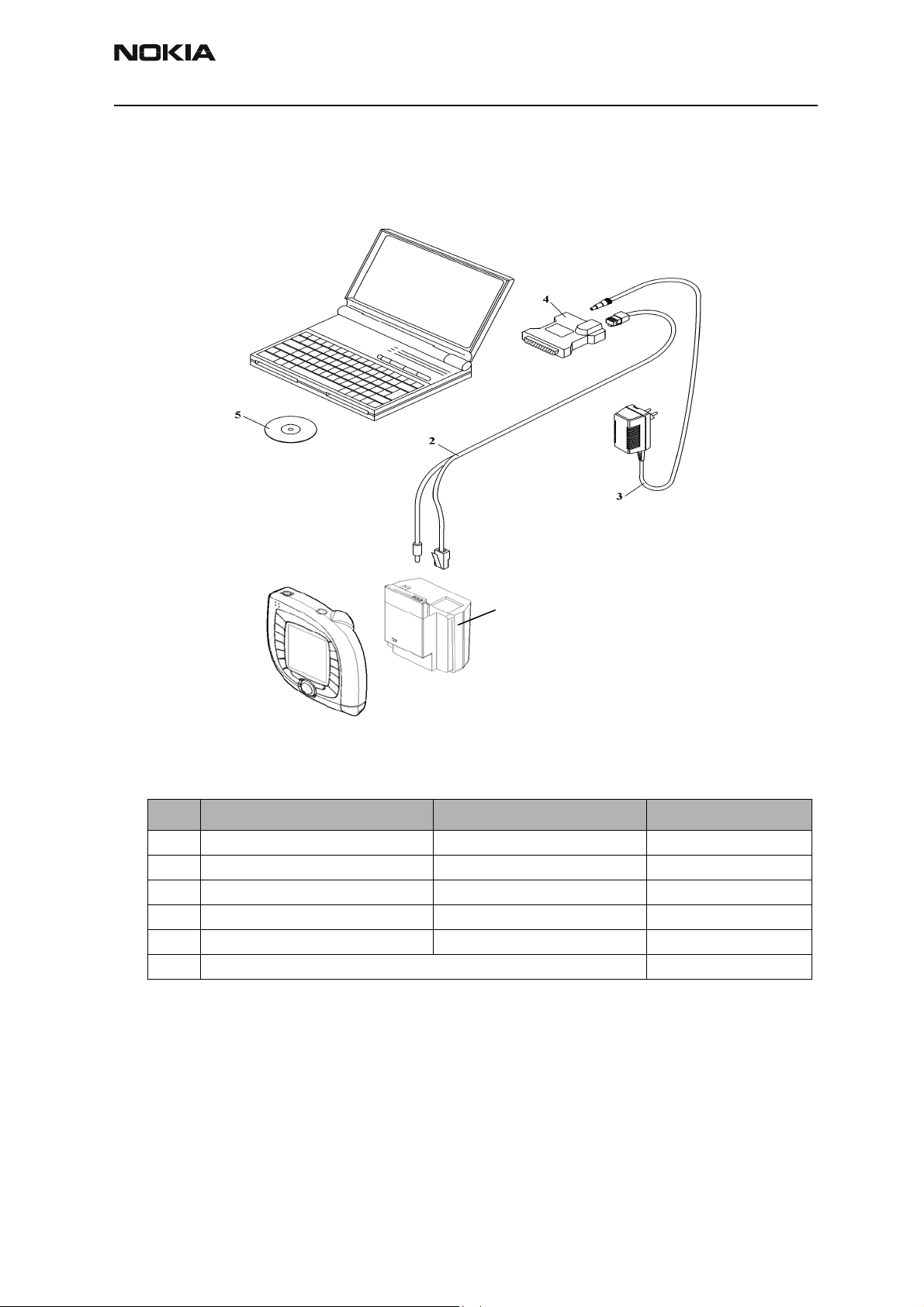
POS Flash concept
1
The following equipment is required for 7600 (NMM-3) AMS SW update, at point of sale
when connecting NMM-3 to PC with FLS-4:
Item Description Type Code
1 Point of Sales flash loading adapter FLA-45 0775340
2 Service cable XCS-1 0730218
3 AC Charger, ACF-8, incl in FPS-4S sales pack 0680032
4 FLS-4S sates pack for E & A FLS-4S 0080541
4 FLS-4S sates pack for APAC FLS-4S 0080542
5 Service SW (downloadable from PWS) xxxxxxxx
Issue 1 (11/2003) Copyright 2003 Nokia Corporation Page 3-9
Company Confidential
Page 10
NMM-3 Company Confidential
3 - Service Software CCS Technical Documentation
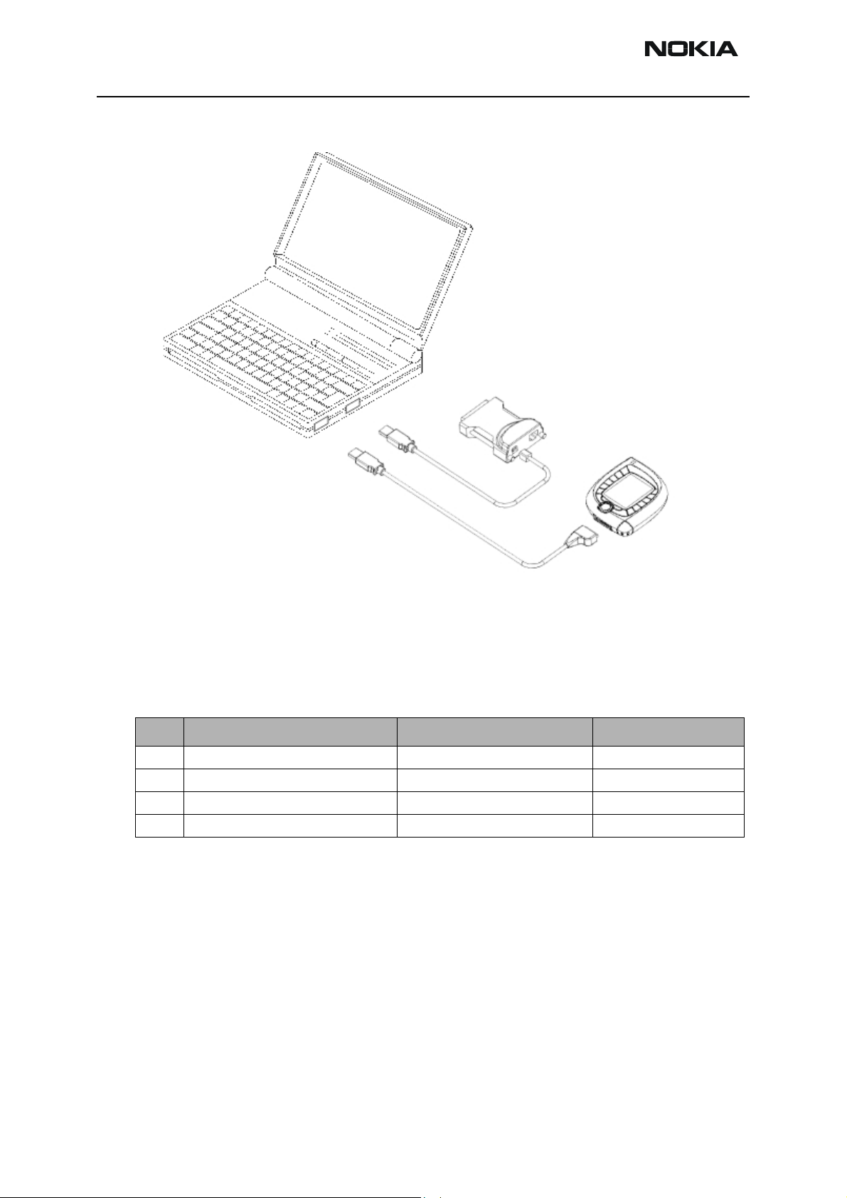
USB Flash concept 1
• Concept 1 (PC must have 2-USB ports) assuming that the laptop parallel port is
used for other purpose.
• The FLS-4S is connected to the Laptop USB port via USB cable as shown above.
• Phone to PC via DKU-2
The following equipment is required for 7600 (NMM-3) USB Flash concept 1 set-up:
Item Description Type Code
1 Pop port cable DKU-2 0273643
2 USB type B cable ~ xxxxxxxx
3 FLS-4S sates pack for E & A FLS-4S 0080541
3 FLS-4S sates pack for APAC FLS-4S 0080542
Page 3-10 Copyright 2003 Nokia Corporation Issue 1 (11/2003)
Company Confidential
Page 11
Company Confidential NMM-3
CCS Technical Documentation 3 - Service Software
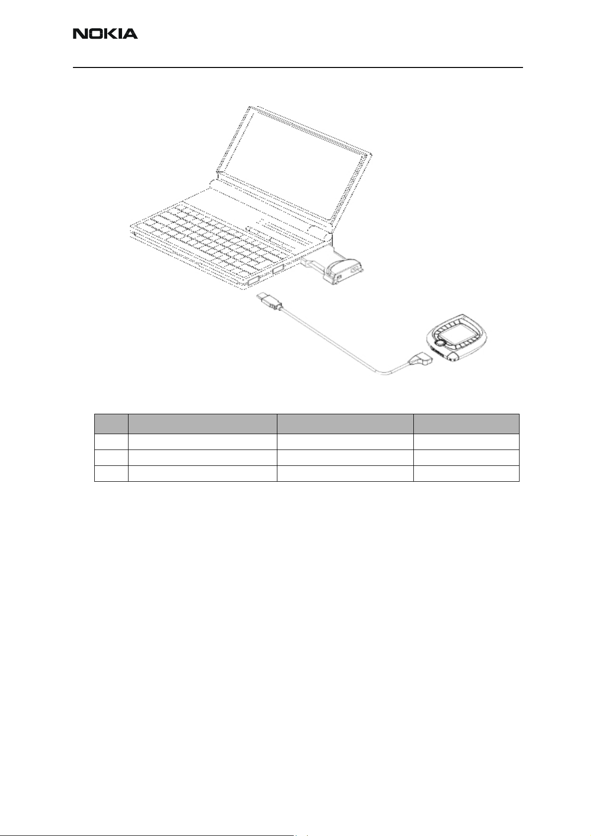
USB Flash concept 2
The following equipment is required for 7600 (NMM-3) USB Flash concept 2 set-up:
Item Description Type Code
1 Pop port cable DKU-2 0273643
2 FLS-4S sates pack for E & A FLS-4S 0080541
2 FLS-4S sates pack for APAC FLS-4S 0080542
NMM-3 Phoenix installation instructions
Now that cables have been connected, you must install NMM-3 version of Phoenix to
your PC.
• Save the package to your hard disk and install it by doubleclicking it.
NOTE: It is recommended that you uninstall previous Phoenix package before installing
the new one. Do it as follows:
• Click Start -> Settings -> Control Panel
• Add/Remove Prog.
• Phoenix NMM-3 release
• Add/Remove
Reboot your computer after uninstallation
Issue 1 (11/2003) Copyright 2003 Nokia Corporation Page 3-11
Company Confidential
Page 12

NMM-3 Company Confidential
3 - Service Software CCS Technical Documentation
FPS-8 to PC connection Setup instructions
Establish connection between your PC and FPS-8. The procedure is as follows:
• Start phoenix
• Choose File -> Manage connections
• Choose Add
• Select mode, select Manual
• As Media, select FPS-8
• Port number, select the port where you have connected the serial cable of FPS-8.
• Select 115200 BIT_RATE
•COMBOX_DEF_MEDIA, select FBUS
• Click on Finish
•Press Arrow up key so that FPS8 COM1 FBUS becomes the first on the list.
• Press Apply and close the window
The connection between PC and FPS-8 has now been configured.
FPS-8 activation
Follow the instructions inside FPS-8 sales pack to get FPS-8 activated.
Checking Application SW version inside FPS-8
When you have connection established to FPS-8 and FPS-8 has been activated, the first
thing to do is to check that you have correct application SW version inside FPS-8. Phoenix SW can check that automatically. The procedure goes as follows:
Go to the partner web site and take newest AMS FPS-8 SW.
Instructions:
• Click Fps-8 downloads
• Click Flash Update
• Click AMS/Production version
• Click 2.10.000
• Take file flash_update_02_10_000.exe
• Save it to your hard drive to a place which you can remember
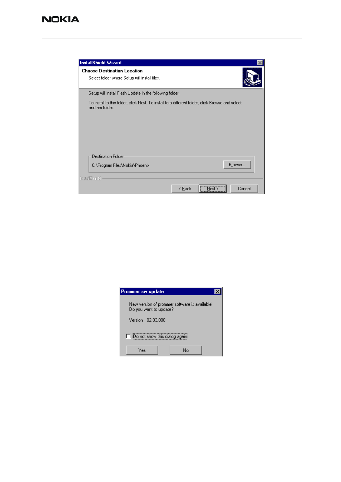
• Go to that directory and click on flash_update_02_10_000.exe
You will see the following note on your screen. Install files to the directory which installation program suggests to you.
Page 3-12 Copyright 2003 Nokia Corporation Issue 1 (11/2003)
Company Confidential
Page 13
Company Confidential NMM-3
CCS Technical Documentation 3 - Service Software
Figure 1: Install Shield Wizard screen
When the installation has been finished, FPS-8 files are located in that directory.
You can now start phoenix SW.
When phoenix SW has stared, do the following:
Click on flashing
Click on FPS-8/FPS-8C Maintenance
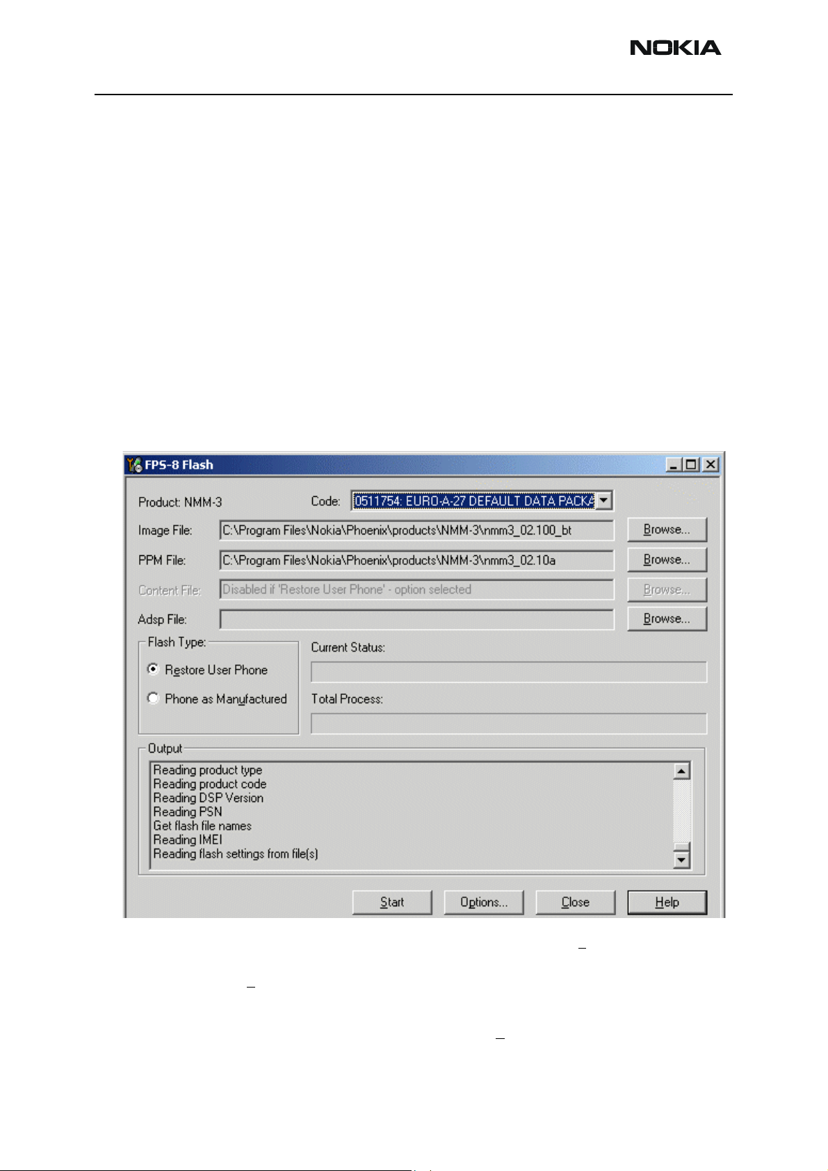
If SW inside FPS-8 prommer is too old, you get the following notification:
Figure 2: Prommer SW update screen
Click Yes and you see on the small scree as the Prommer goes to service mode (mode2 is
lit) SW goes into box, application SW , Secondary boot codes and algorithm codes are
updated.
There is no longer need to do anything special with NMM-3 specific Secondart boot
codes and algorithm codes.
Your PC and FPS-8 is now ready for NMM-3 SW update.
Issue 1 (11/2003) Copyright 2003 Nokia Corporation Page 3-13
Company Confidential
Page 14
NMM-3 Company Confidential
3 - Service Software CCS Technical Documentation
Reprogramming NMM-3
For programming using the FPS-8, remove SIM and attach the FLA-45 adapter or connect to MJF-29/JBV-1 as shown in the FPS-8 Flash setup above. If flashing using the
FLS-4S via USB, power on phone as normal, with SIM fitted and connect DKU-2 Pop port
cable in either of the two USB flash configurations shown above.
Updating Software
The following procedure can be used for updating the phone software.
• Open Phoenix
• Choose File - Manage connections
• Set the required connection method to the top of the priority list and Apply
• Select Flashing and choose either: FPS-8 Flash or FLS-4 Flash depending on
connection method
The Flash window will open.
To restore the user data after the phone has been flashed select Restore User Phone. If
you wish to delete all the user data and return the phone to manufactured state, select
Phone as Manu
• Select the required Image File and PPM File using Browse... buttons on the
Flash File Selection window. If Phone as Manu
the Content File path.
Page 3-14 Copyright 2003 Nokia Corporation Issue 1 (11/2003)
factured.
factured has been selected, enter
Company Confidential
Page 15

Company Confidential NMM-3
CCS Technical Documentation 3 - Service Software
•Do not select an ADSP File.
• Select Start to begin flashing.
• Follow instructions on screen as required.
If flashing is done by the FPS-8 then the software package is first transferred to the FPS8, this process may be slow, in which case, it is recommended that the parallel port is
configured in ECP mode. If you do not know how to change the parallel port mode contact your local support.
If flashing is done using the FLS-4S with USB then the ADL package is first down loaded,
this is a phone application that manages the USB flashing process.
Erasing of the phone memory is then carried out.
Finally the software package is programmed into the phone, and the user data, if
requested, is restored.
Service Tool Concepts for Calibration
Calibration can be carried out using:
• MJS-84 Module Jig
• JBV-1 Docking station with MJF-29 Docking Station Adapter for NMM-3
Power to the MJS-84 or JBV-1 should be supplied from an external DC power supply, not
the FPS-8 prommer.
Remember cable attenuation when tuning RF power settings.
Issue 1 (11/2003) Copyright 2003 Nokia Corporation Page 3-15
Company Confidential
Page 16

NMM-3 Company Confidential
3 - Service Software CCS Technical Documentation
Calibration Set-up using MJS-84
Number Type Description Code
1 MJS-84 Module jig 0770590
2 PCS-1 DC power cable 0730012
3 XRF-1 RF antenna cable 0730085
4 DAU-9S Service MBUS cable 0730108
5 PKD-1 Software protection key
(Dongle)
0750018
Page 3-16 Copyright 2003 Nokia Corporation Issue 1 (11/2003)
Company Confidential
Page 17

Company Confidential NMM-3
CCS Technical Documentation 3 - Service Software
Calibration Set-up using JBV-1
Number Type Description Code
1 JBV-1 Docking station 0770298
2 MJF-29 Docking station adapter 0770592
3 SCB-3 DC-DC cable 0730114
4 XRF-1 Antenna cable 0730085
5 PCS-1 DC power cable 0730012
6 DAU-9S Service MBUS cable 0730108
7 PKD-1 Software protection key
(Dongle)
8 Phoenix Service SW
0750018
Issue 1 (11/2003) Copyright 2003 Nokia Corporation Page 3-17
Company Confidential
Page 18

NMM-3 Company Confidential
3 - Service Software CCS Technical Documentation
Energy Management Calibration
Energy management calibration should be carried out after any of the following:
• Replacement of UEME
• Replacement of ZOCUS (IBAT only)
• Replacement of Flash 0 (D450)
Automatic Calibration
It is recommended that Energy Management calibration is done automatically using the
JBV-1 as follows:
Connections
The NMM-3 phone must be connected to JBV-1 (Docking station) with MJF-29 (Docking
station adapter).
• Connect CA-5S (DC-DC cable) from JBV-1 into to phone charger connector before powering up JBV-1.
• Power up JBV-1 from external power supply: 11-16 V DC. (Do not take power from FPS-8
in calibration mode).
Phoenix Setup
• Start Phoenix
•Select File - Manage connections - FBUS and apply
•Select File - Scan Product
•Select M
aintenance -> Tuning -> Energy Management
Page 3-18 Copyright 2003 Nokia Corporation Issue 1 (11/2003)
Company Confidential
Page 19

Company Confidential NMM-3
CCS Technical Documentation 3 - Service Software
Calibration
Figure 3: Energy Management Calibration screen
• Press the Calibrate button
• After calibration is complete, the calculated values are shown in the Calculated
column. Select the Write to PM button to store values to phone.
• The Read from PM button can be used to confirm that the values have been
written to the phone or to compare calculated values with current phone values.
Issue 1 (11/2003) Copyright 2003 Nokia Corporation Page 3-19
Company Confidential
Page 20

NMM-3 Company Confidential
3 - Service Software CCS Technical Documentation
Limits For Energy Management Calibration
Measurement Reference Low Limit High Limit
ADC Offset -50 50
Gain 26500 28500
Battery Size Gain 900 1200
Battery Voltage Offset 2400 2600
Gain 10000 11000
Charger Voltage Gain 57500 62500
Charger Current Offset -200 200
Gain 4100 6000
Battery Current Gain 1 255
GSM Tuning
General remarks on GSM RF Tuning
• RF tunings must be made in the same order as shown in this document. The order
of the menu items in the Phoenix service software may be different.
• If baseband tunings are needed, they should be made before the RF tunings.
• After tuning is completed the mode must be set manually to dual mode. This
must be done to ensure that the phone is not registering only to WCDMA mode!
• Avoid unnecessary tuning - factory tuning values are always the most accurate
ones.
• Views in this document may change as the service software is developed. Please
refer to the Phoenix help files. phone model specific service manual and bulletins
for help.
Introduction
The following outlines the test method for the alignment of the NMM-3 GSM transceiver
using Phoenix.
Receiver tunings
RX Channel Select Filter Calibration
• Extra equipment / external RF signal not needed
• Must be done before other RX calibrations
• This function is used to calibrate RX channel select filter in GSM Phones.
• Rx Channel select filter is tuned only in one band = Single calibration for both
bands
Page 3-20 Copyright 2003 Nokia Corporation Issue 1 (11/2003)
Company Confidential
Page 21

Company Confidential NMM-3
CCS Technical Documentation 3 - Service Software
• Select > Tuning >GSM> Rx Channel select filter calibration
• Press “Tune” to start the tuning
• Press “stop “ to end the tuning, results will automatically be saved to phone
RX Calibration
• RF generator needed
• This tuning performs RX Calibration
• Must be done separately on both bands!
• Start RX Calibration at EGSM (GSM900), then do RX Calibration at GSM1800
• AFC tuning is done while EGSM (GSM900) band RX Calibration is performed.
• Remember to take jig and cable attenuations into account!
memory.
band.
• Select >Tuning >GSM > Rx calibratio
Issue 1 (11/2003) Copyright 2003 Nokia Corporation Page 3-21
Company Confidential
Page 22

NMM-3 Company Confidential
3 - Service Software CCS Technical Documentation
• Press “start”
• Set RF generator to required frequency > OK
Tuning values and ADC readings will be shown
Typical values and limits in (GSM900/GSM1800) RX Calibration:
GSM900 GSM 1800
Name
Typ. LL UL Typ. LL UL
A F C v a l u e 100 -350 350 - - AFC slope 270 150 350 - - RSSI 0 65 58 68 62 58 68
RSSI 1 71 64 74 68 64 74
RSSI 2 77 70 80 74 70 80
RSSI 3 83 76 86 80 76 86
Page 3-22 Copyright 2003 Nokia Corporation Issue 1 (11/2003)
Company Confidential
Page 23

Company Confidential NMM-3
CCS Technical Documentation 3 - Service Software
GSM900 GSM 1800
Name
Typ. LL UL Typ. LL UL
RSSI 4 89 82 92 86 82 92
RSSI 5 94 88 98 92 88 98
RSSI 6 100 94 104 98 94 104
RSSI 7 105 100 110 104 100 110
RSSI 8 111 106 11 6 110 106 11 6
RSSI 9 11 7 11 2 122 11 6 112 122
RSSI 10 123 11 8 128 122 11 8 128
RSSI 11 130 124 134 128 124 134
RSSI 12 136 130 140 134 130 140
RSSI 13 142 136 146 140 136 146
RSSI 14 147 142 152 146 142 152
• If values shown are within limits, choose “Save and Continue” to save values to
the phone
• Continue tuning from GSM1800.
• When asked, set RF generator to required frequency > OK
Issue 1 (11/2003) Copyright 2003 Nokia Corporation Page 3-23
Company Confidential
Page 24

NMM-3 Company Confidential
3 - Service Software CCS Technical Documentation
• If values shown are within limits, choose “Save & Continue” to save values to the
phone
• Close the “RX Calibration” window to end tuning
RX Band Filter Response Compensation
• RF generator needed
• Must be done separately on both bands!
• Start RX Band Filter Response Compensation at EGSM (GSM900), then do RX
Band Filter Response Compensation at GSM1800 band.
Note: Remember to do RX calibration before doing Rx Band Filter Response
Compensation!
• Remember to take jig and cable attenuations into account!
• Select Tuning>GSM> Rx band filter response compensation
Page 3-24 Copyright 2003 Nokia Corporation Issue 1 (11/2003)
Company Confidential
Page 25

Company Confidential NMM-3
CCS Technical Documentation 3 - Service Software
• Select “Manual Tuning”
• Select “start” to start tuning with values already saved to the phone
• You will be asked to supply 9 different RF frequencies to the phone
Issue 1 (11/2003) Copyright 2003 Nokia Corporation Page 3-25
Company Confidential
Page 26

NMM-3 Company Confidential
3 - Service Software CCS Technical Documentation
• Select “OK” for every step/frequency
• Repeat the same steps as above for all 9 different frequencies
Typical values and limits in Rx Band Filter Response Compensation EGSM900:
Channel
Limits
965 923.26771 -0.672 -10 +5
975 925.26771 0.109 -5 +5
987 927.66771 0.750 -5 +5
1009 932.06771 0.109 -5 +5
37 942.46771 1.047 -5 +5
90 953.06771 0.109 -5 +5
11 4 957.86771 0.859 -5 +5
124 959.86771 0.953 -5 +5
136 962.26771 0.328 -10 +5
• If values are within limits select “Save & Continue” to save values to phone
memory
Input frequency
(MHz)
Measured level
d i f f e r e n c e ( d B )
Lower
Limit
(dB)
Upper
Limit
(dB)
Page 3-26 Copyright 2003 Nokia Corporation Issue 1 (11/2003)
Company Confidential
Page 27

Company Confidential NMM-3
CCS Technical Documentation 3 - Service Software
• Continue tuning from GSM1800.
• Repeat the same steps as for the EGSM900 band above
Typical values and limits in Rx Band Filter Response Compensation GSM1800:
Channel
Limits
497 1802.26771 -0.125 -10 +5
512 1805.26771 -0.500 -5 +5
535 1809.86771 -0.813 -5 +5
606 1824.06771 0.547 -5 +5
700 1842.86771 0.844 -5 +5
791 1861.06771 -1.031 -5 +5
870 1876.86771 0.047 -5 +5
885 1879.86771 0.391 -5 +5
908 1884.46771 0.703 -10 5
• If values shown are within limits, select “OK” to save values to the phone
Input frequency
(MHz)
Measured level
d i f f e r e n c e ( d B )
Lower
Limit
(dB)
Upper
Limit
(dB)
• Close the “RX Band Filter Response Compensation” – dialog to end tuning
Issue 1 (11/2003) Copyright 2003 Nokia Corporation Page 3-27
Company Confidential
Page 28

NMM-3 Company Confidential
3 - Service Software CCS Technical Documentation
Rx DtoS Balance Calibration
• External RF Signal not Required
• Must be done on both bands
• Function is to calibrate DSP Software DtoS I-Q-channel control word values
• Select >Tuning>GSM>Rx DtoS Balance Calibration
• Select “Start”
• Select “PM Values” to start tuning with values already saved to the phone
Page 3-28 Copyright 2003 Nokia Corporation Issue 1 (11/2003)
Company Confidential
Page 29

Company Confidential NMM-3
CCS Technical Documentation 3 - Service Software
• Select “Save & Continue” to start the tuning
• Continue Tuning for GSM1800 Select “Save & Continue” to start the tuning
• Typical values for GSM1800 are shown below
Transmitter Tunings
TX I/Q Tuning
• Spectrum analyser needed. Use 10dB external pad
• Tx IQ Tuning allows changing the Tx I DC Offset, Tx Q DC Offset, Amplitude difference and Phase difference
• Must be done separately on both bands!
• Start TX I/Q Tuning at EGSM (GSM900), then continue at GSM1800 band.
• Remember to take jig and cable attenuations into account!
• Select >Tuning >GSM>Tx IQTuning
Issue 1 (11/2003) Copyright 2003 Nokia Corporation Page 3-29
Company Confidential
Page 30

NMM-3 Company Confidential
3 - Service Software CCS Technical Documentation
• Select “ Start”
• The tuning is done by setting each of the sliders to desired value. The sliders can
be changed only when the tuning is ongoing
• The order of tuning should be same as the order of the sliders e.g. the Tx I DC Offset is tuned first and Phase difference is tuned last
• Use PgUp or PgDn keys, arrow keys can be used for fine tuning
• Set spectrum analyser to the settings on the screen
Page 3-30 Copyright 2003 Nokia Corporation Issue 1 (11/2003)
Company Confidential
Page 31

Company Confidential NMM-3
CCS Technical Documentation 3 - Service Software
• Tune LO leakage to minimum with TXI/TXQ DC offset control (f0 on spectrum
analyser screen)
• Tune unwanted sideband (fo + 67kHz) to minimum using Amplitude/Phase difference controls
Typical TX IQ Tuning Values and tuning limits GSM 900:
Parameter Typ. Value Low Limit High Limit
I DC Offset -2.5…+0.5 -6 +6
Q DC Offset -2.5…+0.5 -6 +6
Amplitude difference -0.2…+0.2 -1 +1
Phase difference 88.0°….92.0° 80° 100°
• If values shown are within limits, check the “Save & Continue” to save the new
values to the product
Issue 1 (11/2003) Copyright 2003 Nokia Corporation Page 3-31
Company Confidential
Page 32

NMM-3 Company Confidential
3 - Service Software CCS Technical Documentation
• Continue tuning from GSM1800
• Set spectrum analyser to the settings on the screen
• Repeat the same steps as for the EGSM900 band
Typical TX IQ Tuning Values and tuning limits GSM1800:
Parameter Typ. Value Low Limit High Limit
I DC Offset -3.0…0.0 -6 +6
Q DC Offset -1.5…+1.0 -6 +6
Amplitude difference -0.5…+0.0 -1 +1
Phase difference 90.0°…97.0° 80° 100°
• If values shown are within limits, select the “Save & Continue” to save the new
values to the product
• Close the “TX I/Q Tuning” – dialog to end tuning
TX Power Level Tuning
• Vector Signal Analyser (or spectrum analyser) needed
• With Tx Power Level Tuning, the coefficients are adjusted for each power level
• Must be done separately on both bands!
• Start Power Level tuning at EGSM (GSM900) Edge OFF band, then continue for
GSM1800 Edge OFF band
• In EGSM900 band the power level tuning is made for both high and low PA
Modes
• In GSM1800 band only for high PA mode
• Remember to take jig and cable attenuations into account!
• Tuning > GSM > Tx power level tuning
Page 3-32 Copyright 2003 Nokia Corporation Issue 1 (11/2003)
Company Confidential
Page 33

Company Confidential NMM-3
CCS Technical Documentation 3 - Service Software
• Select “Start”
Note: the PA Mode is “High” at this point
• The coefficient table lists the power level, coefficient, target dBm value for each
power level
• The tuned power level can be chosen by using up and down arrows or mouse.
• The current power level is shown with inverse colours
• The tuning value can be adjusted with “-“ and “+” keys
• Tune base level and power levels 19, 15 and 5 to target level
Issue 1 (11/2003) Copyright 2003 Nokia Corporation Page 3-33
Company Confidential
Page 34

NMM-3 Company Confidential
3 - Service Software CCS Technical Documentation
• Press “Save & Continue”
• The TxPA Mode has changed to “Low“
• Tune power levels 19, 15 and 7 (Levels 5 & 6 are not used, base level tuning not
required)
Page 3-34 Copyright 2003 Nokia Corporation Issue 1 (11/2003)
Company Confidential
Page 35

Company Confidential NMM-3
CCS Technical Documentation 3 - Service Software
Typical values: EGSM900
Power level PA high mode PA low mode
5 700 -
7 520 15 211 213
19 180 180
Base 163 163
• Select “Save & Continue” to save values to phone permanent memory
• Continue tuning for GSM1800 Edge OFF band.
• Repeat the same steps as for the EGSM900 band above
Note: that In GSM1800 band tuning is only made in “High” mode
Typical values: GSM1800
Power level PA high mode
0 748
11 192
15 169
Base 150
• Select “Save & Continue” to save values to phone permanent memory
• Close the “TX Power Level Tuning” – dialog to end tuning
Issue 1 (11/2003) Copyright 2003 Nokia Corporation Page 3-35
Company Confidential
Page 36

NMM-3 Company Confidential
3 - Service Software CCS Technical Documentation
WDCMA Tuning
The following contains information about Rf tunings with Phoenix software. Also there is
information about WCDMA RF controls and tests run with this software.
WCDMA RF Tunings
• Order for WCDMA RF tunings:
• RX/TX channel filter calibration
• Temperature sensor calibration
• RX AGC tuning
• RX band response
• TX bias current setting
• TX AGC tuning
• TX power detector tuning
• TX band response
• To run these with Phoenix SW, the phone must be in local mode with “WCDMA”
system selected.
Note: When WCDMA tuning has finished the system selected must be
changed back to dual mode otherwise the customer won’t be able to register
with a gsm network.
WCDMA RF Channel Filter Calibration
• This does not require any external instruments.
• Run this component from the Phoenix menu:
Tunings/WCDMA/RF channel filter calibration.
• This is the initial view. Press “Tune” to start calibration.
Note: You can also read values from memory with “Read”.
Page 3-36 Copyright 2003 Nokia Corporation Issue 1 (11/2003)
Company Confidential
Page 37

Company Confidential NMM-3
CCS Technical Documentation 3 - Service Software
Save the tuned values into PM
(PM = permanent memory)
The tuned values are settings for the baseband analog active low pass filters in REX and
TEX ASICs.
WCDMA Temperature Sensor Calibration
• This does not require any external instruments.
• The phone must be at room temperature for this calibration.
• Run this component from the Phoenix menu:
Tunings/WCDMA/Temperature sensor calibration.
• This is the initial view. Press “Tune” to run the calibration.
Note: By pressing “Read”, the saved value can be read from PM
Save tuned value
into PM
The value stored is a DC-voltage from the temperatur sensor in TEX. It’s value is the difference between the expected value for room temperature so it can be either ±.
WCDMA RX AGC Alignment
• A signal generator is needed to provide a test signal into the WCDMA RF test
connector.
• Calibration is started from the Phoenix menu:
Tunings/WCDMA/RX AGC Alignment
Issue 1 (11/2003) Copyright 2003 Nokia Corporation Page 3-37
Company Confidential
Page 38

NMM-3 Company Confidential
3 - Service Software CCS Technical Documentation
• Press “Start” then “Tune”.
• The calibration routine will define the signal generator settings for you.
• When you have applied the test signal - click “OK”.
• The calibration values are then calculated and stored into PM.
Note: With the “Read” - button you can check the values stored in PM.
Page 3-38 Copyright 2003 Nokia Corporation Issue 1 (11/2003)
Company Confidential
Page 39

Company Confidential NMM-3
CCS Technical Documentation 3 - Service Software
Definitions of the parameters saved are:
RX chain gain: This is the overall receiver gain error compared to expected value
in dB’s.
LNA mid gain error: This is the difference in LNA’s gain step compared to expected
value in dB’s.
LNA low gain error: This is the difference in LNA’s gain step compared to expected
value in dB’s.
AGC slope error: This is the gain slope error in the baseband analog AGC gain stages.
LNA bias error: This is the difference in the LNA maximum gain with full and half
bias current.
WCDMA RX Band Response Calibration
• A signal generator is needed and test signal applied into NMM-3’s RF test con-
nector.
• Calibration is started from the Phoenix menu:
Tunings/WCDMA/RX band response calibration
• Press “Start” then “Tune”.
• The calibration routine will define the signal generator settings for you.
• Set frequency and settings to defined values and allow the tuning to continue by
pressing “OK”.
Issue 1 (11/2003) Copyright 2003 Nokia Corporation Page 3-39
Company Confidential
Page 40

NMM-3 Company Confidential
3 - Service Software CCS Technical Documentation
• After this low and high frequency compensation values for RX band response will
be stored into PM when you press “Yes” to save changes.
Note: With the “Read” - button you can check the values stored in PM.
WCDMA TX PA Bias Tuning
• With this tuning the power supply to the phone must be set to 3.6V.
• Calibration is started from the Phoenix menu:
Tunings/WCDMA/TX PA bias tuning
• Press “Start” .
• After pressing the “OK” button read the lowest current consumption from current
meter (of the phone). Increase the PA Bias DAC value with the arrow buttons
until the tuned current has increased by the 25mA target.
Page 3-40 Copyright 2003 Nokia Corporation Issue 1 (11/2003)
Company Confidential
Page 41

Company Confidential NMM-3
CCS Technical Documentation 3 - Service Software
• Press “Finish”, and save the tuning value for PA bias
The tuning value sets the IPA1 current output from UEM that determines the bias current
of the second stage of the WCDMA PA.
WCDMA TX AGC Alignment
• This alignment requires the use of a vector signal analyser or spectrum analyser.
• Calibration is started from the Phoenix menu:
Tunings/WCDMA/TX AGC alignment
• Press “Start” .
• The program asks do you want to read PM values or use current values or
defaults. When running for the first time use defaults. Press “OK”.
• Connect the analyser into the WCDMA RF test connector
Issue 1 (11/2003) Copyright 2003 Nokia Corporation Page 3-41
Company Confidential
Page 42

NMM-3 Company Confidential
3 - Service Software CCS Technical Documentation
• The phone will send a power ramp sequence at 1950Mhz at 7 different power
levels. The actual signal is at 1950.3MHz, since the transmitter is modulated with
a 300kHz IQ-sinewave.
• Set the analyser to 1950.3MHz 100kHz RBW, sweeptime 2.0 ms, video triggering
used with trace averaging. Set the ref. level first to +25 dBm, then decrease it to
get a more accurate reading when taking a measurement.
Example shown using an Agilent E4406A
• Read power levels for slots from ramp into TXA 2 table and press “Enter” to run
the ramp for 2nd AGC-stage.
• Fill the power levels from the 2nd ramp into TXA 1 table and press “Enter”.
Page 3-42 Copyright 2003 Nokia Corporation Issue 1 (11/2003)
Company Confidential
Page 43

Company Confidential NMM-3
CCS Technical Documentation 3 - Service Software
• After filling in the measured power levels for both AGC-stages (TXA1 for TEX and
TXA2 for HEX), Phoenix calculates a set of coefficients and parameters to build a
model for TX AGC behaviour. Store them into PM.
WCDMA TX Power Detector Calibration
• This alignment requires the use of a power meter (“thermal” sensor) or vector
signal analyser. The wideband mean power should be measured in a 3.84MHz
RBW.
• Calibration is started from the Phoenix menu:
Tunings/WCDMA/Power detector calibration
• Press “Start” .
Issue 1 (11/2003) Copyright 2003 Nokia Corporation Page 3-43
Company Confidential
Page 44

NMM-3 Company Confidential
3 - Service Software CCS Technical Documentation
• Tune the output power with the slider to +21 dBm. The power can be set with
either the slider or the arrow keys on the keyboard. Press “Accept”
• In the 2nd phase, the output power is tuned to +11 dBm.
• Press “Accept”. The tuned coefficients V0 and V1 are calculated.
Note: With the “Read” - button you can check the values stored in PM.
WCDMA TX Band Response Calibration
• This alignment requires the use of a power meter (“thermal” sensor) or vector
signal analyser.
• Calibration is started from the Phoenix menu:
Tunings/WCDMA/TX Band Response Calibration
Page 3-44 Copyright 2003 Nokia Corporation Issue 1 (11/2003)
Company Confidential
Page 45

Company Confidential NMM-3
CCS Technical Documentation 3 - Service Software
Press “Start”
Tune the power at mid channel using the spin button to get a reading of 21 dBm on the
tester. Press the “Accept” button.
Note: With the “Read” - button you can check the values stored in PM.
• Change tester to low channel
• Read value from tester and enter it to Low Power Level Field. Press the “Accept”
button
Issue 1 (11/2003) Copyright 2003 Nokia Corporation Page 3-45
Company Confidential
Page 46

NMM-3 Company Confidential
3 - Service Software CCS Technical Documentation
• Change tester to high channel
• Read value from tester and enter it to High Power Level Field. Press the Accept”
button.
• Save values to PM when complete.
WCDMA RF Testing Using Local Mode
Phoenix supports the following functions in local mode:
• TX control using either direct power control or uplink power control
• RX control to LNA and BB AGC. Algorithm Mode supports the RSSI measurements
WCDMA TX Control
• Two modes are available:
• Manual mode is for direct control of the AGC’s, PA Bias - and DC/DCconverters. Also, modulation type, channel settings and different kinds of
sweeps with DACs can be run to study the phones behaviour
• Algorithm mode can be used when TX (AGC’s) are calibrated. Output
power can be set to fixed power levels or power sweeps can be run. Also
WCDMA signal code settings (scrambling and channelisation codes can
be modified).
• WCDMA TX control can be activated from Phoenix-menu:
Testing/WCDMA/Tx Control
• Manual mode:
DA-converter setting for AGC’s in TEX and HEX (0…1023 )
DA-converter for PA bias control ( 0…12 )
DA-converter setting for DC/DC-converter ( 112 … 512;
112 DAC~1.5 V DC/DC output voltage, 512 DAC ~3.3V )
Modulation selection is for WCDMA Signal or CW Signal
Here the uplink data- and control channel weighting can
be adjusted ( 0…15 )
Uplink channel number can be changed in here ( 9612 …
9888 ).
NOTE: When settings are done, they’re enabled after
pressing ”Send”. If settings are then changed ( e.g. new
channel number ) you must press ”Stop” and ”Send” again.
Page 3-46 Copyright 2003 Nokia Corporation Issue 1 (11/2003)
Company Confidential
Page 47

Company Confidential NMM-3
CCS Technical Documentation 3 - Service Software
• Algorithm mode:
Uplink power level ( open loop power ), ( -57 … +21 dBm )
Step size (in dB’s + or - ) and step counts for power sweeps.
Sequence is for how many sweeps wanted
Step duration is the length of the step in us (max 2550 us )
Uplink scrambling code and type can be selected here
Here the uplink data- and control channelization code
numbers and weighting can be adjusted ( 0…15 ). Code
classes for those define the bit rates ( spreading factors ).
e.g. DPDCH code class 6 stands for spreading factor 60 and
8 in DPCCH is for SF 256. These SF’s are used in 12.2.kpbs
uplink voice channel.
Uplink channel number can be changed in here ( 9612 …
9888 ).
NOTE: When settings are done, they’re enabled after
pressing ”Send”. If settings are then changed ( e.g. new
channel number ) you must press ”Stop” and ”Send” again.
WCDMA RX Control
• Two modes are available: Manual or algorithm.
• WCDMA RX control can be activated from Phoenix-menu
• Received signal power measurements are possible with the algorithm mode in Rx
control.
Testing/WCDMA/Rx Control
In manual mode the LNA with 3 different gain steps and BB
AGC can be controlled.
AFC DA-converter can be adjusted ( 0… 2047, 1024 middle
value ). NOTE: If TX control is activated the AFC control can
be done from here.
Channel number for downlink can be set here ( 10562 …
10838 )
RX control can be activated by pressing ”Update”. Again if
changes are made into settings, they are valid after
pressing ”RF Stop” then ”Update”
NOTE: ”RF Stop” also disables TX control if that was active !
• Rx power measurements can be activated from Phoenix-menu:
Issue 1 (11/2003) Copyright 2003 Nokia Corporation Page 3-47
Company Confidential
Page 48

NMM-3 Company Confidential
3 - Service Software CCS Technical Documentation
Testin/WCDMA/Rx Power Measurement
Example of an RSSI measurement.
Feed a CW or WCDMA modulated signal from a generator into the antenna connector
and set “AGC Mode” to algorithm in the Rx control window. Press “Start”.
Select RSSI in measurement mode.
Press “Start Measure”
The result should be in dBm.
Page 3-48 Copyright 2003 Nokia Corporation Issue 1 (11/2003)
Company Confidential
 Loading...