

Page 1

Customer Care Solutions
NMM-3 Series Cellular Phones
5 - Disassembly Instructions
Issue 1 (11/2003) Copyright 2003 Nokia Corporation. Page 5-1
Company Confidential
Page 2

NMM-3 Company Confidential
5 - Disassembly Instructions CCS Technical Documentation
Table of Contents
Description Page No.
Disassembly Instructions
Disassembly Instructions ............................................................................................................... 3
Re-assembly Instructions .............................................................................................................. 11
Assembly of B-Cover Module ................................................................................................ 11
Assemble of UI Module ........................................................................................................... 14
Assembly of the ATO ................................................................................................................ 16
Assembly of the Transceiver .................................................................................................. 18
Visual Quality Check during Re-assembly ................................................................................ 20
Page 5-2 Copyright 2003 Nokia Corporation. Issue 1 (11/2003)
Company Confidential
Page 3
Company Confidential NMM-3
CCS Technical Documentation 5 - Disassembly Instructions
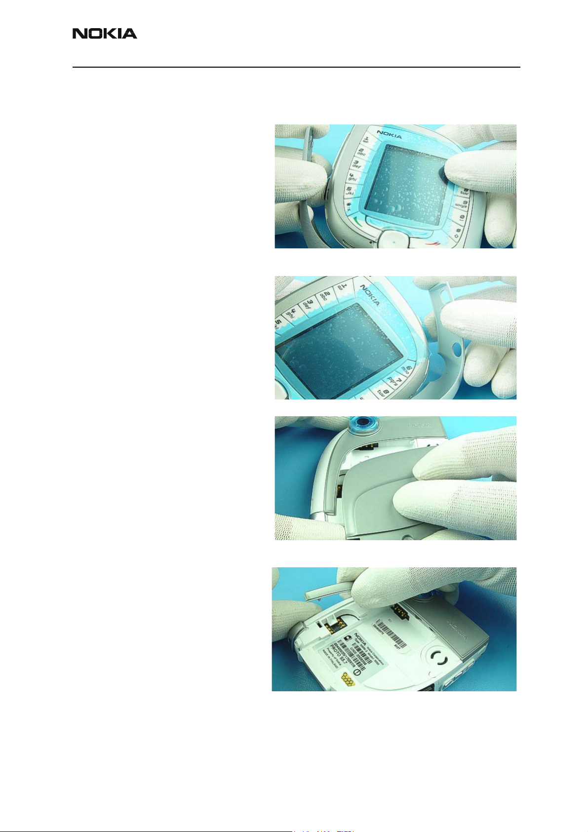
Disassembly Instructions
1. First remove LH Sleeve.
2. Now remove RH Sleeve.
1
2
3. Dismount C-Cover.
4. Pull up D-cover, which is attached
to B-cover with adhesive tape.
3
4
Issue 1 (11/2003) Copyright 2003 Nokia Corporation. Page 5-3
Company Confidential
Page 4
NMM-3 Company Confidential
5 - Disassembly Instructions CCS Technical Documentation
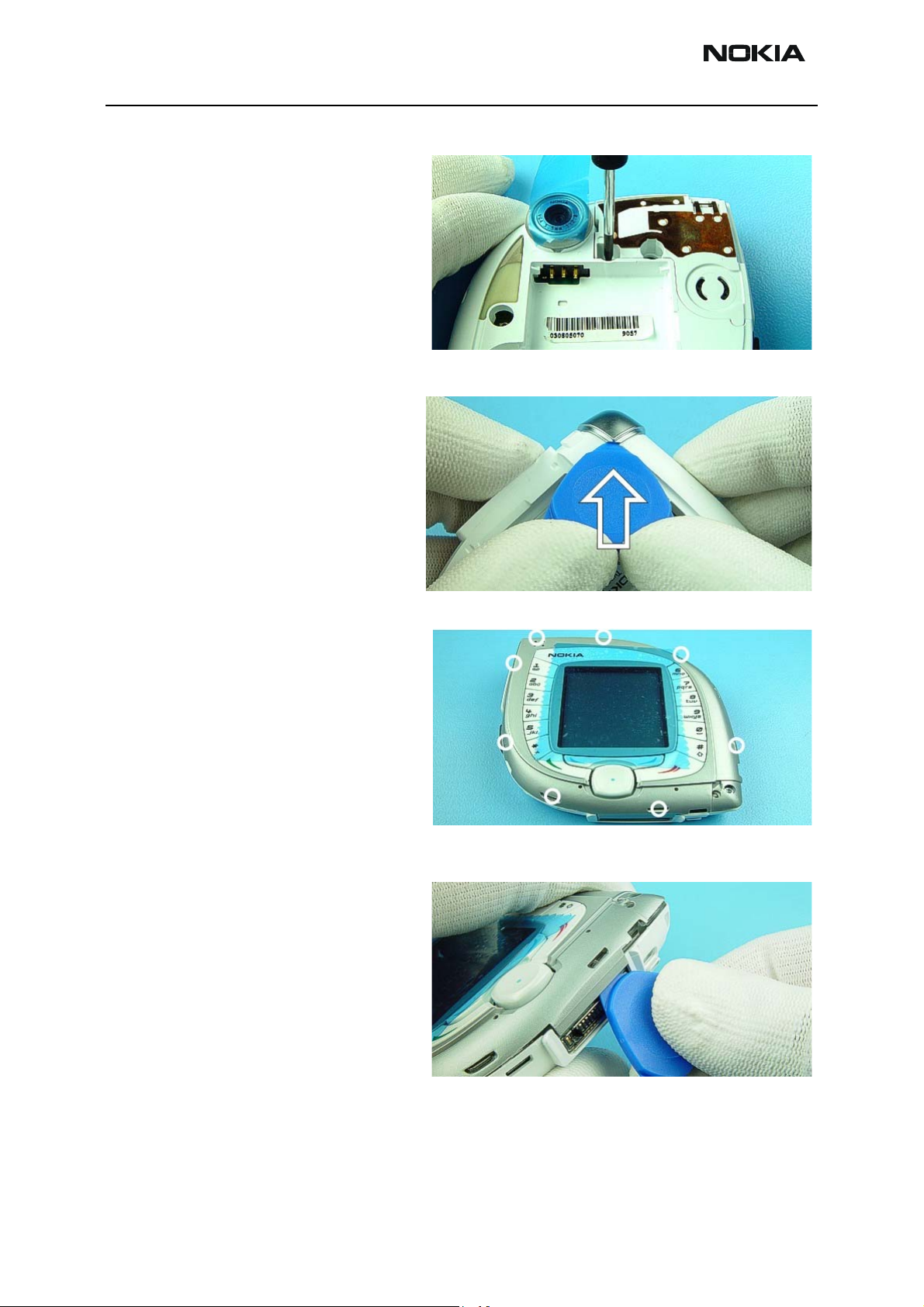
5. Unscrew Antenna screw. Use a new
Torx Plus screw and a torque of 26
Ncm for assembly.
6. The Corner Piece fits very tight, so
it needs some extra force to separate
it from the B-cover with the SRT-6.
5
6
7. The A-cover is fixed with several
plastic clips. Start with the clip near
to the system connector.
8. Loosen the clips anti-clockwise by
using the SRT-6 as a lever. Do not
twist the SRT-6 because this could
cause damage to the cover.
7
8
Page 5-4 Copyright 2003 Nokia Corporation. Issue 1 (11/2003)
Company Confidential
Page 5
Company Confidential NMM-3
CCS Technical Documentation 5 - Disassembly Instructions
9. Remove A-cover.
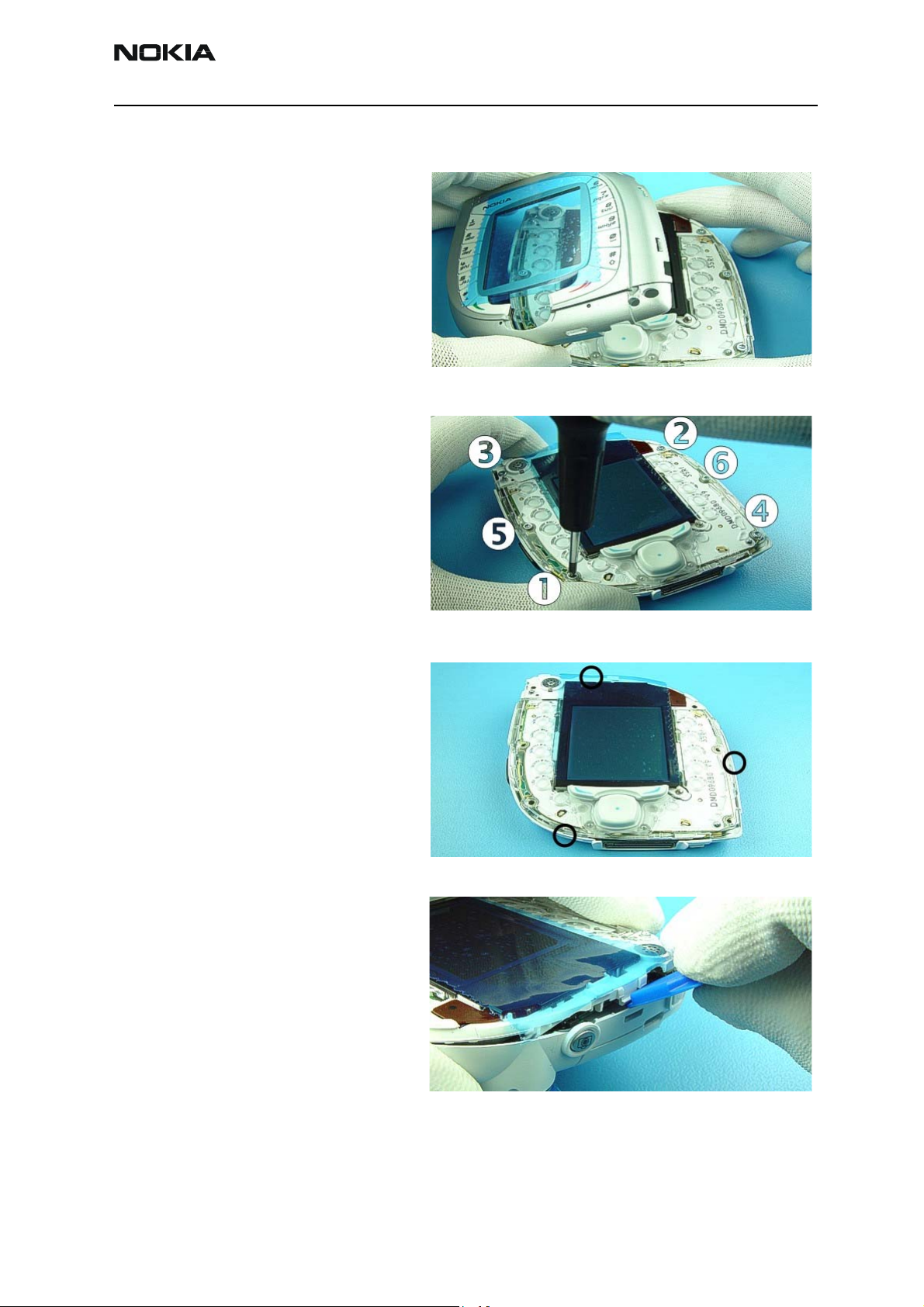
10. Unscrew the six Torx Plus screws
using the order shown. For assembly
the reverse order and a torque of 19
Ncm has to be used for an old Bcover and 22 Ncm for a new B-cover.
No electric or air driver are allowed
to be used for assembly.
9
10
11. Unlock the three clips from the UI
Assembly, as indicated.
12. If unlocking doesn’t work check
that the Antenna screw has been
removed.
11
12
Issue 1 (11/2003) Copyright 2003 Nokia Corporation. Page 5-5
Company Confidential
Page 6
NMM-3 Company Confidential
5 - Disassembly Instructions CCS Technical Documentation
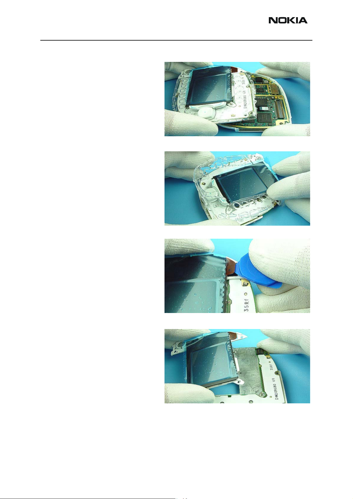
13. Remove UI Assembly.
14. After opening the side clips the
Lightguide can be removed.
13
14
15. Carefully open LCD Connector
with the SRT-6. Do not damage the
sensitive flex foil.
16. Remove LCD.
15
16
Page 5-6 Copyright 2003 Nokia Corporation. Issue 1 (11/2003)
Company Confidential
Page 7

Company Confidential NMM-3
CCS Technical Documentation 5 - Disassembly Instructions
17. Press out Earpiece from guiding
pin side.
18. Separate UI PWB from Engine
Shield.
17
18
19. Dismount Engine module.
20. Use disassembly side of the SRT11 to remove the VGA Camera. Use
the other side of the SRT-11 for
assembly.
19
20
Issue 1 (11/2003) Copyright 2003 Nokia Corporation. Page 5-7
Company Confidential
Page 8

NMM-3 Company Confidential
5 - Disassembly Instructions CCS Technical Documentation
21. Lever out WCDMA Antenna from
B-cover.
22. Using a charger plug remove the
DC Jack.
21
22
23. Remove Vibra Motor, taking care
not to damage the spring contacts.
24. Unlock the side snaps to remove
the IT Window.
23
24
Page 5-8 Copyright 2003 Nokia Corporation. Issue 1 (11/2003)
Company Confidential
Page 9

Company Confidential NMM-3
CCS Technical Documentation 5 - Disassembly Instructions
25. Push out the Volume Keys, taking
care not to damage the silicon.
26. Remove the Microphone from its
guidance.
25
26
27. Remove Camera Shutter Key.
28. Remove Power Key.
27
28
Issue 1 (11/2003) Copyright 2003 Nokia Corporation. Page 5-9
Company Confidential
Page 10

NMM-3 Company Confidential
5 - Disassembly Instructions CCS Technical Documentation
29. Detach Camera Window by placing SRT-6 as shown and pressing
upwards forcefully.
30. Press out Rubber Gasket from the
outside.
29
30
31. There are two plastic clips, which
have to be unlocked before removing
GSM Antenna.
32. Finally remove HF Speaker with
tweezers.
31
32
Page 5-10 Copyright 2003 Nokia Corporation. Issue 1 (11/2003)
Company Confidential
Page 11

Company Confidential NMM-3
CCS Technical Documentation 5 - Disassembly Instructions
Re-Assembly Instructions
Assembly of B-Cover Module
1. Assemble the Handsfree Speaker
1
into the GSM antenna housing making sure to apply even pressure
around the circumference of the
device. Ensure the alignment feature
on the device is aligned to the relevant feature in the antenna housing.
Note: Ensure the contacts are
avoided and the speaker gauze is first
fitted to the GSM antenna module.
2
2. Snap the GSM antenna module
onto the B-Cover module ensuring
the clip nearest the camera window is
engaged first, whilst taking care to
ensure the speaker contacts are
aligned inside the B-Cover aperture
before all clips are assembled to avoid
any damage to them.
Note: The GSM antenna module will
not sit parallel to the B-Cover when it
is assembled. There will be a gap next
to the speaker - this is normal.
3. Fit the camera window gasket/
3
boot onto the B-Cover moulding
ensuring first that the B-Cover is
internal side up so you can see the
alignment of the gasket with the
three alignment clips into the BCover recesses.
Note: Ensure that the annulus of the
camera boot is concentric with the BCover camera annulus.
Issue 1 (11/2003) Copyright 2003 Nokia Corporation. Page 5-11
Company Confidential
Page 12

NMM-3 Company Confidential
5 - Disassembly Instructions CCS Technical Documentation
4. Turn the B-Cover over once the
4
boot is aligned and push the boot
retention clips into the recesses in
the B-Cover so they are visible from
the outside of the B-Cover.
5. Assemble the camera window
6
adhesive to the camera window
annulus on the B-Cover, ensuring it is
centrally fitted and the yellow backing tape is removed.
6. Align the camera window to the
B-Cover using the alignment feature
in both the window and the B-Cover.
Press down on the edges of the window (taking care not to damage it)
until all three clips snap home to the
B-Cover.
Note: Ensure the B-Cover is supported underneath when the window is assembled. Assembly
force must be at least 60N/cm² for at least 6 seconds.
7. Take an IR window and snap it into
7
the B-Cover ensuring that it is orientated the correct way around. Assemble the right hand side clip first into
the B-Cover then snap the second
clip into place.
Note: Ensure the front and back of
the window is not cosmetically damaged by wearing soft gloves when
pressure is applied to the window.
Page 5-12 Copyright 2003 Nokia Corporation. Issue 1 (11/2003)
Company Confidential
Page 13

Company Confidential NMM-3
CCS Technical Documentation 5 - Disassembly Instructions
8. Assemble the WCDMA antenna
8
into the B-Cover module ensuring the
antenna is engaged under the clip
nearest the battery bay wall before
the external clip is made by pushing
down on the antenna to clip it to the
B-Cover.
Note: Ensure the clips are engaged
by checking the clip is within the clip
aperture of the outside of the BCover. Ensure also that the metallization on the antenna is not scratched
or contaminated.
9. Assemble all electromechanical
9
devices into their specific apertures
(i)
provided for them in the B-Cover
module, including the vibra, microphone and DC Jack. Ensure each
device is fully assembled into their
individual cavities and in the correct
orientation as illustration opposite
indicates.
Note: Ensure the contacts on each
device are avoided and the DC Jack
snapped home.
9 (ii). Removing the microphone.
9
(ii)
Issue 1 (11/2003) Copyright 2003 Nokia Corporation. Page 5-13
Company Confidential
Page 14

NMM-3 Company Confidential
5 - Disassembly Instructions CCS Technical Documentation
9 (iii). Removing the Vibra Motor.
9
(iii)
10. Ensure each of the three keys is
10
fully assembled into their apertures.
Ensure the bottom of the key is
aligned into the B-Cover with the
face being pushed through the aperture in the B-Cover. The key flanges
must be tight up against the B-Cover
flange with no gap.
Assembly of UI Module
Note: Ensure the Class I faces of the
keys are not touched or damaged
during the assembly sequence.
1. Place the earpiece into the LCD
1
frame, ensuring the alignment feature on the device is aligned with the
slot in the frame. Press the device
into the frame.
Note: Ensure the metal body of the
earpiece is not distorted and the contacts are not deformed. Ensure the
earpiece is fully assembled into the
LCD frame.
Page 5-14 Copyright 2003 Nokia Corporation. Issue 1 (11/2003)
Company Confidential
Page 15

Company Confidential NMM-3
CCS Technical Documentation 5 - Disassembly Instructions
2. Assemble the UI PWB Module onto
2
the Engine shield ensuring the shield
is kept flat and not distorted or bent.
The PWB must be LED’s up and care
must be taken not to touch the board
to board connector pads.
Note: Ensure the datum pins on the
shield are not deformed.
3. Assemble the LCD module onto the
3
UI shield assembly, ensuring the clip
at the top & middle of the frame near
the ear piece is assembled first and
then the bottom frame location hole
is assembled over the shield pin.
Note: Ensure the LCD is kept flat at
all times and only ever handled from
the sides. The protective tape must be
kept on the LCD during handling and
assembly.
4. Clip the male LCD connector on
4
the LCD module into the female LCD
connector on the UI PWB, ensuring to
align the devices first. The connector
should snap into place.
Note: The connector must be assembled keeping it flat and applying even
pressure across the top of the rigidiser.
Issue 1 (11/2003) Copyright 2003 Nokia Corporation. Page 5-15
Company Confidential
Page 16

NMM-3 Company Confidential
5 - Disassembly Instructions CCS Technical Documentation
5. Place a Navi key assembly onto the
5
UI PWB, ensuring the alignment pips
on the bottom of the Navi key assembly are located into the holes in the
UI PWB.
Note: Ensure the Class I surfaces of
the Navi key are kept clean and
undamaged. These must be checked
before assembly.
6. Place a lightguide assembly onto
6
the UI module assembly, sliding the
top right lightguide tab under the
LCD frame first, then clipping the
right then left clips to the engine
shield and finally placing the top left
lightguide alignment hole over the
top left engine shield alignment pin.
Assembly of ATO Module
Note: Ensure the lightguide is not
distorted and the side clips are fully
assembled and not cracked. Also
ensure that all LED’s are within the
recesses in the lightguide provided for
them.
1. Assemble the engine PWB onto
the UI module (making sure the module is first placed LCD down). Ensure
the engine is located onto the engine
shield alignment pins.
Note: Ensure the board to board connector and camera assembly are
avoided by only holding the PWB
module in the designated areas indicated.
Protection Pad (not supplied)
Page 5-16 Copyright 2003 Nokia Corporation. Issue 1 (11/2003)
Company Confidential
Page 17

Company Confidential NMM-3
CCS Technical Documentation 5 - Disassembly Instructions
2. Assemble the camera into the
2
camera connector using the SRT-11
Camera Assembly tool.
Note: Ensure the alignment pip on
the SRT-11 Camera Assembly tool is
aligned with the pip on the camera
which is in turn aligned with the dot
on the camera connector assembly
before location and assembly. Also
ensure that the camera has all three
clips connected to the shield.
3. Assemble the B-Cover module
3
onto the UI & PWB modules. Locate
the top of the phone first to avoid
damage to the camera and camera
shield and so the two alignment pins
on the engine shield find their location holes in the B-Cover.
Protection Pad (not supplied)
Note: Ensure the alignment of the B-
Cover module is correct by aligning it
gently before the clipping of the two
modules. Take extra care as this is a
blind assembly.
4. Clip all three UI module to B-Cover
4
module clips together ensuring the
top clip is made first followed by the
clip by the system connector and
then finally the clip on the side.
Note: Ensure pressure is only applied
directly above the clips.
Issue 1 (11/2003) Copyright 2003 Nokia Corporation. Page 5-17
Company Confidential
Page 18

NMM-3 Company Confidential
5 - Disassembly Instructions CCS Technical Documentation
5
5. Assemble the 7th screw into the
back of the B-Cover making sure not
to damage the B-Cover. This screw
must be a new 5.3mm x 1.6mm T6
(IP6) machine screw (NMP 6150905)
with an orange threadlock patch
applied with a torque of 26 Ncm.
Note: Only use a hand torque driver.
6. Assemble the 6 screws into the
6
ATO in the order indicated opposite.
Using new 9.0mm x 1.6mm T6 Remform screws (NMP 6150903). A
torque of 19 Ncm must be applied to
these screws when an old B-cover is
re-used and 22 Ncm for a new cover.
Assembly of Transceiver
Ensure the screws heads are sitting
flush on the lightguide or LCD frame.
Note: Only use a hand torque driver.
1. Assemble the A-Cover module
1
onto the ATO module using the clipping sequence outlined opposite,
ensuring clip number one is slid onto
the lightguide clip (pressure must
only be applied to the edge of the ACover over the clips and NOT over the
LCD).
Note 1: Each of the clips must be
checked for correct assembly in
which case the clip must be fully visible within the A-Cover aperture.
Make sure the blind clip over the system connector (9) is also assembled.
Note 2: Make sure the LCD protective tape is removed before assembly of A-Cover module.
Page 5-18 Copyright 2003 Nokia Corporation. Issue 1 (11/2003)
Company Confidential
Page 19

Company Confidential NMM-3
CCS Technical Documentation 5 - Disassembly Instructions
2. APAC ONLY - The tamper proof
2
label must be fitted across the split
line of the A-Cover and B-Cover in
the place indicated in the illustration
opposite.
3. Assemble the corner piece onto
3
the ATO module ensuring the top side
is placed in its retention recess within
the A-Cover first. Pushing the corner
piece downwards snaps the bottom
clip home.
Note: Be sure to only apply pressure
to the corner piece and that the component is the correct way around.
4. Assemble the D-Cover module to
4
the ATO module by firstly removing
the protective tape from the adhesive
at the back of the D-Cover and then
clipping the D-Cover clips to the ATO
in order shown opposite.
Note: Apply light pressure across the
D-Cover once assembled to ensure
the adhesive takes. Ensure gloves are
used and the cosmetic Class I painted
surface of the D-Cover is not damaged or contaminated in any way.
Issue 1 (11/2003) Copyright 2003 Nokia Corporation. Page 5-19
Company Confidential
Page 20

NMM-3 Company Confidential
5 - Disassembly Instructions CCS Technical Documentation
Visual Quality Checks during Re-assembly
• Ensure the window in the A-Cover module has no contamination, scratches or
wear in the viewing area of any kind
• Ensure the camera window viewing area is clear of contaminants or defects
• Ensure the corner piece is correctly fitted and free from contaminants or defects
• Ensure the side keys all depress
• Ensure all 7 screws are fitted and fully assembled
• Ensure the keymat and navi key are free from contaminants or defects
• Ensure the C and D-Covers as well as the painted surface on the A-Cover are free
from contaminants or defects
• Ensure all nine A-Cover clips are fully assembled
• Ensure the window border colour is the same colour as the A-Cover
• Ensure the window has protective tape fitted
• Ensure the camera window has protective tape fitted
• Ensure none of the A-Cover clips are broken
• Ensure all three UI module to B-Cover module clips are made
• Ensure there is no contamination or damage in the B-Cover battery bay area
• Ensure the LCD protective tape and D-Cover adhesive backing tapes have been
removed
• Ensure the phone is free from dust or hairs
Page 5-20 Copyright 2003 Nokia Corporation. Issue 1 (11/2003)
Company Confidential
 Loading...