

Page 1

Customer Care Solutions
NMM-3 Series Transceivers
4 - Service Tools
Issue 1 (11/2003) Copyright 2003 Nokia Corporation
Company Confidential
Page 2

NMM-3 Company Confidential
4 - Service Tools CCS Technical Documentation
Table of Contents
Page No
JBV-1 Docking Station and MJF-29 Adapter................................................................................... 3
MJS-84 Module Jig .................................................................................................................................4
MJS-85 Soldering Jig .............................................................................................................................5
SRT-6 Opening Tool ................................................................................................................................5
SRT-11 Camera Removal Tool.............................................................................................................. 6
FPS-8 Flash Prommer (Sales Pack) ..................................................................................................... 6
ACF-8 Universal Power Supply .............................................................................................................7
FPS-8C Parallel Flash Prommer (Sales Pack) ................................................................................... 7
FLS-4S POS (Point Of Sale) Flash Device (Sales Pack).................................................................. 8
FLA-45 POS (Point Of Sale) Flash Loading Adapter....................................................................... 8
FLC-2 DC Cable ........................................................................................................................................ 9
AXS-4 Service Cable ............................................................................................................................ 10
XCS-1 Service Cable ..............................................................................................................................10
SW Security Device PKD-1 ............................................................................................................... 11
PCS-1 Power Cable .............................................................................................................................. 11
CA-24RS RF Cable................................................................................................................................ 12
XRF-1 RF Cable...................................................................................................................................... 12
DAU-9S MBUS Cable........................................................................................................................... 13
SCB-3 DC Cable..................................................................................................................................... 13
XCS-4 Modular Cable.......................................................................................................................... 14
Printer Cable .......................................................................................................................................... 14
Appendix 4-A Guideline For First Lead Free Products........................................................... 15
Page 4-2 Copyright 2003 Nokia Corporation Issue 1 (11/2003)
Company Confidential
Page 3
Company Confidential NMM-3
CCS Technical Documentation 4 - Service Tools
JBV-1 Docking Station and MJF-29 Adapter
The JBV-1 Docking Station has been designed for calibration and software update use.
The MJF-29 Docking Station Adapter makes signal connections to the phone. JBV-1 and
MJF-29 are used as one unit.
JBV-1 main electric functions are:
• adjustable VBATT calibration voltage, current measurement limit voltage ”VCHAR”,
current measurement calibration current ”ICHAR”
• adjustable ADC calibration voltage for BSI
• BSI calibration resistor
• FBUS signal routing to handset
• controlled via FBUS or USB
• Programming Pass / FAIL indication
In calibration mode JBV-1 is powered by external supply set at 11-16V DC. During flashing power is supplied from the FPS-8 or FLS-4S.
Product Code
JBV-1 Docking Station: 0770298
MJF-29 Docking Station Adapter: 0770592
View of MJF-29
Figure 1: MJF-29
Issue 1 (11/2003) Copyright 2003 Nokia Corporation Page 4-3
Company Confidential
Page 4
NMM-3 Company Confidential
4 - Service Tools CCS Technical Documentation
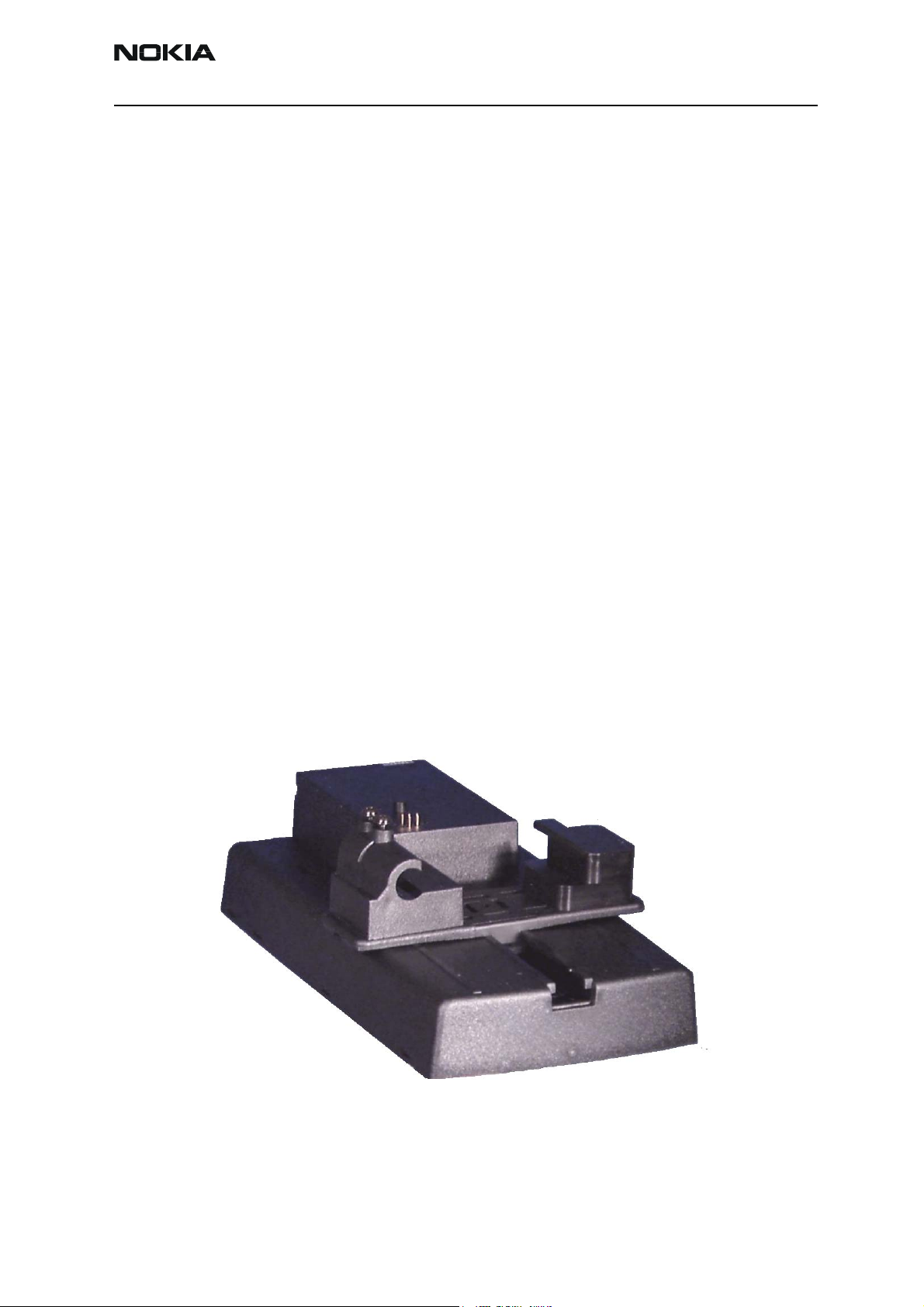
MJS-84 Module Jig
The MJS-84 Module Jig is used for faultfinding and testing the following modules:
• User Interface
• Baseband and RF on system module
Product Code
MJS-84 Module Jig: 0770590
View of MJS-84
Figure 2: MJS-84
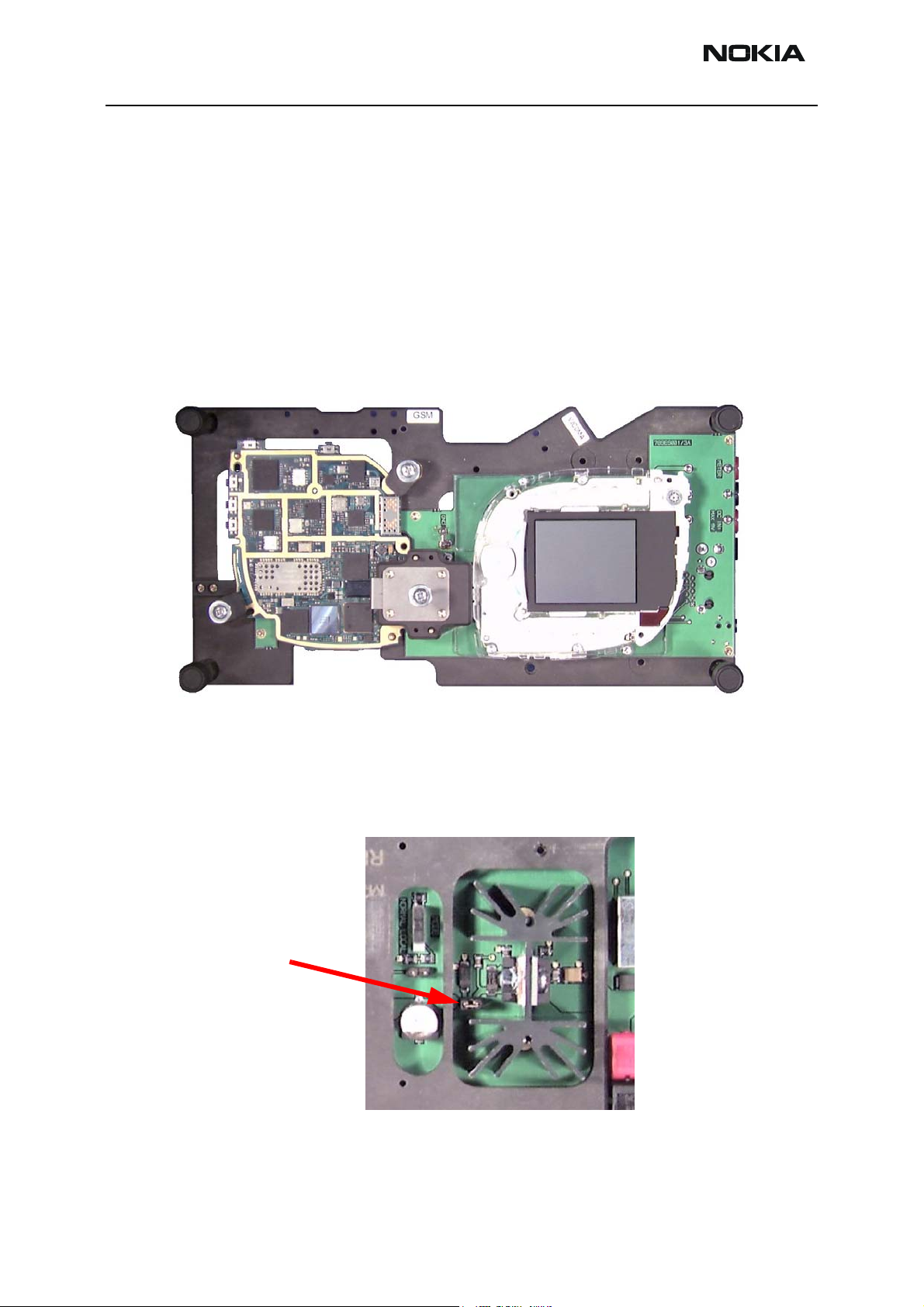
*Note: Power to the MJS-84 can be supplied in three ways; 5V to 9V connected to the jack
or ‘DC IN’ banana socket or Vbat direct (3.2V to 4.2V) via the ‘METER’ connector (using
this method the jumper must be removed otherwise excessive current will be drawn
through the jig current sink. See Figure 3).
Figure 3:
Jumper
A charger can be connected to the charger jack, ensure that the phone supply is connected to the ‘DC IN’ and that the jumper is also connected.
Page 4-4 Copyright 2003 Nokia Corporation Issue 1 (11/2003)
Company Confidential
Page 5
Company Confidential NMM-3
CCS Technical Documentation 4 - Service Tools
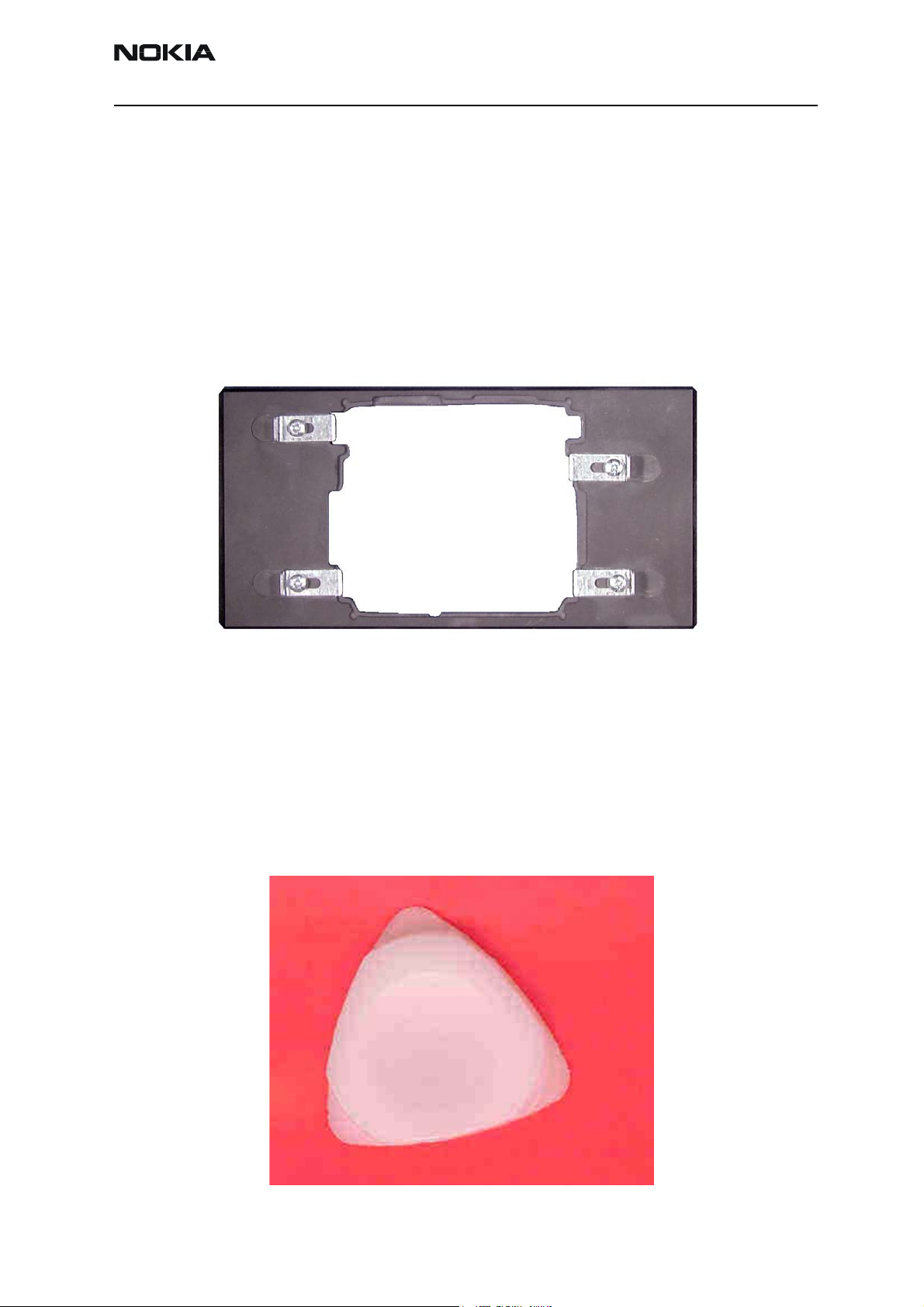
MJS-85 Soldering Jig
The Soldering Jig MJS-85 is used to support the engine module during soldering and
rework.
Product Code
MJS-85 Soldering Jig: 0770591
View of MJS-85
Figure 4: MJS-85
SRT-6 Opening Tool
The Opening Tool is to assist in the mechanical disassembly of the NMM-3.
Product Code
SRT-6 Opening Tool: 0770431
View of SRT-6
Figure 5: SRT-6
Issue 1 (11/2003) Copyright 2003 Nokia Corporation Page 4-5
Company Confidential
Page 6
NMM-3 Company Confidential
4 - Service Tools CCS Technical Documentation
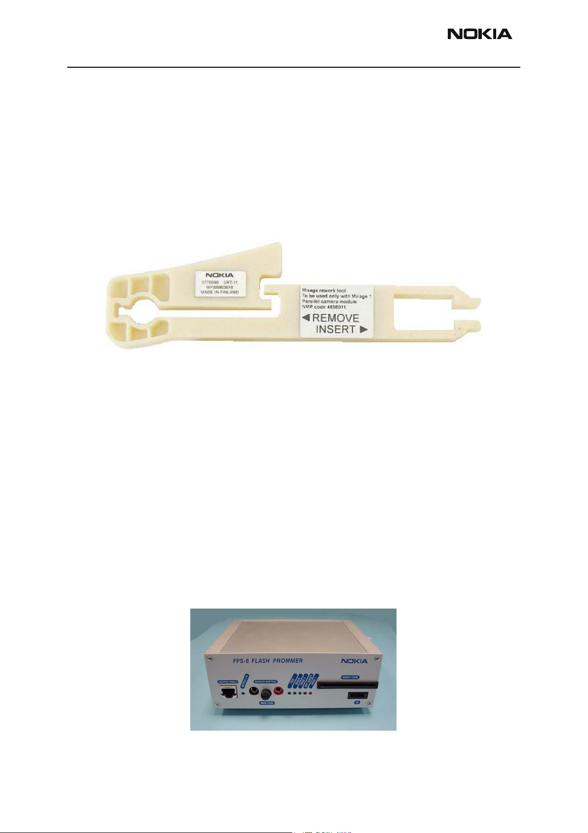
SRT-11 Camera Removal Tool
The Camera Removal Tool SRT-11 is used to remove the camera from its locking connector.
Product Code
SRT-11 Camera Removal Tool: 0770580
View of SRT-11
Figure 6: SRT-11
FPS-8 Flash Prommer (Sales Pack)
The FPS-8 Flash Prommer in conjunction with JBV-1 / MJS-84 is used for programming
and updating the phone software. Power is supplied to FPS-8 from the Universal Power
Supply.
The sales pack includes: - FPS-8 Flash Prommer 0750123
- FPS-8 Activation Sheet 9359289
- Universal Power Supply 0680032
- AXS-4 Service Cable (D9-D9) 0730090
- Printer cable 0730029
Sales package code
FPS-8 Flash Prommer: 0080321
View of FPS-8
Figure 7: FPS-8
Page 4-6 Copyright 2003 Nokia Corporation Issue 1 (11/2003)
Company Confidential
Page 7

Company Confidential NMM-3
CCS Technical Documentation 4 - Service Tools
ACF-8 Universal Power Supply
The ACF-8 Universal Power Supply is used to power FPS-8, it provides 2.1A at 6V DC.
Product Code
ACF-8 Universal Power Supply: 0680032
View of ACF-8
Figure 8:
FPS-8C Parallel Flash Prommer (Sales Pack)
The FPS-8C Parallel Flash Prommer is used with the JBV-1 / MJS-84. A maximum of 8
phones can be flashed simultaneously. The FPS-8C consists of eight SF11C programming
cards. SF11C card is functionally identical to FPS-8.
Sales package code
FPS-8C Parallel Flash Prommer: 0080396
View of FPS-8C
Figure 9: FPS-8C
Issue 1 (11/2003) Copyright 2003 Nokia Corporation Page 4-7
Company Confidential
Page 8

NMM-3 Company Confidential
4 - Service Tools CCS Technical Documentation
FLS-4S POS (Point Of Sale) Flash Adapter (Sales Pack)
The FLS–4S POS Flash Adapter connects to the PC parallel port, it is used in conjunction
with the FLA-45 POS Flash Loading Adapter for programming and updating the phone
software. Power is supplied to the FLS-4S from a ACF-8 Universal power supply.
The sales pack includes:
• FLS-4S Flash Dongle See below
• User Guide
• ACF-8 Universal Power Supply 0680032
• Device Driver software
Product Code
FLS-4S Sales Pack – Europe/Africa 0080541
FLS-4S Sales Pack –APAC 0080542
FLS-4S Sales Pack –Americas 0080543
View of FLS-4S
Figure 10: FLS-4S
FLA-45 POS (Point Of Sale) Flash Loading Adapter
The FLA-45 POS Flash Loading Adapter FLA-48 is used in place of the phone’s normal
battery during service. It supplies a controlled operating voltage and is connected to the
FLS-4S when flash programming. Connection between the FLS-4S and FLA-45 is made
using the VCS1 cable.
Product Code
FLA-45 POS Flash Loading Adapter: 0775340
Page 4-8 Copyright 2003 Nokia Corporation Issue 1 (11/2003)
Company Confidential
Page 9

Company Confidential NMM-3
CCS Technical Documentation 4 - Service Tools
View of FLA-45
Figure 11: FLA-45
FLC-2 DC Cable
The FLC-2 is used to supply a controlled operating voltage to FLA-48 adapter.
Product Code
FLC-2 DC Cable: 0730185
View of FLC-2
Figure 12: FLC-2
Issue 1 (11/2003) Copyright 2003 Nokia Corporation Page 4-9
Company Confidential
Page 10

NMM-3 Company Confidential
4 - Service Tools CCS Technical Documentation
AXS-4 Service Cable
The AXS-4 D9-D9 Service Cable is used to connect two 9 pin D connectors e.g. between
PC and FPS-8. Cable length is 2 meters.
Product code
AXS-4 D9-D9 Service Cable: 0730090
View of AXS-4
Figure 13: AXS-4
XCS-1 Service Cable
The XCS-1 Service Cable is used to connect FLS-4 to FLA-48.
Product code
XCS-1 Service Cable: 0730218
View of XCS-1
Figure 14: XCS-1
Page 4-10 Copyright 2003 Nokia Corporation Issue 1 (11/2003)
Company Confidential
Page 11

Company Confidential NMM-3
CCS Technical Documentation 4 - Service Tools
SW Security Device PKD-1
SW security device is a piece of hardware enabling the use of the service software when
connected to the parallel (LPT) port of the PC. Whithout the dongle present it is not possible to use the service software. Printer or any such device can be connected to the PC
through the dongle if needed.
Caution: Make sure that you have switched off the PC and the printer before making connections!
Caution: Do not connected the PKD-1 to the serial port. Product Code
SW Security Device PKD-1: 0750018
View of SW Security Device
Figure 15: PKD-1
PCS-1 Power Cable
The PCS-1 Power Cable (DC) is used to connect e.g. JBV-1 or MJS-31 to FPS-8.
Product Code
PCS-1 Power Cable: 0730012
View of PCS-1
Figure 16: PCS-1
Issue 1 (11/2003) Copyright 2003 Nokia Corporation Page 4-11
Company Confidential
Page 12

NMM-3 Company Confidential
4 - Service Tools CCS Technical Documentation
CA-24RS RF Cable
RF cable CA-24RS is used to connect e.g. ............................................... to RF measurement
equipment.
Product code
CA-24RS RF Cable: 0730315
View of CA-24RS
Figure 17: CA-24RS
TBD
XRF-1 RF Cable
RF cable XRF-1 is used to connect e.g. MJS-51, CPL-5, TDS-10 or RA7 to RF measurement
equipment..
Product code
XRF-1 RF Cable: 0730085
View of XRF-1
Figure 18: XRF-1
Page 4-12 Copyright 2003 Nokia Corporation Issue 1 (11/2003)
Company Confidential
Page 13

Company Confidential NMM-3
CCS Technical Documentation 4 - Service Tools
DAU-9S MBUS Cable
The MBUS Cable DAU-9S has a modular connector, and is used with between PC’s serial
port and e.g. MJS-51, FLA-48, or JBV-1
Product Code
DAU-9S MBUS Cable: 0730108
View of DAU-9S
Figure 19: DAU-9S
SCB-3 DC Cable
The DC Cable SCB-3 is used to connect e.g. JBV-1 to the phone.
Product Code
SCB-3 DC Cable: 0730114
View of SCB-3
Figure 20: SCB-3
Issue 1 (11/2003) Copyright 2003 Nokia Corporation Page 4-13
Company Confidential
Page 14

NMM-3 Company Confidential
4 - Service Tools CCS Technical Documentation
XCS-4 Modular Cable
XCS-4 is a shielded cable (one specially shielded conductor) modular cable for flashing
and service purposes.
Product code
XCS-4 Modular Cable: 0730178
View of XCS-4
Figure 21: XCS-4
Printer Cable
This cable is used to connect the PC to FPS-8.
Product code
Printer Cable: 0730029
View of Printer Cable
Figure 22: Printer Cable
Page 4-14 Copyright 2003 Nokia Corporation Issue 1 (11/2003)
Company Confidential
Page 15

Company Confidential NMM-3
CCS Technical Documentation 4 - Service Tools
Appendix 4-A Guideline For First Lead Free Products
CONTENTS
1. Scope
2. SnPb / Pb Free Process
2.1 Pb (Sn62Pb36Ag2) Product
2.2 Pb Free (Sn95.5Ag3.8Cu0.7) Product
2.3 Mixed Component Product
3. Rework Method
4. Rework Material
5. Rework Equipment and Tools
5.1 Manual Soldering Using Soldering Iron
5.2 Manual and Semi-automatic Hot Gas Soldering
6. Rework Station Heating Profile
6.1 Profile Measurement Method on PWBs for Rework Station
6.2 Measuring procedure
6.3 Sample Profile
1. Scope
This guideline is designed to be used in NMP manufacturing. It is the first guideline for
lead free rework process for product programs. Specific work instructions must be created on the basis of this guideline. This document will be updated all the time.
Specifications, parameters and work methods are not described in this, so document follow other MES specifications.
2. SnPb / Pb Free Process
The paste used in the production process also defines the process. If a process makes use
of paste that contains lead, it is called a normal process, whereas a process relying on
lead free paste is called a lead-free process.
2.1 Pb (Sn62Pb36Ag2) Product
In rework, use is made of paste containing Pb, with Pb solder wire. The rework station
uses the Pb-process profile.
2.2 Pb Free (Sn95.5Ag3.8Cu0.7) Product
In rework, only Pb-free paste, solder wire and Pb-free components are used. The rework
station uses the Pb-free process profile.
Issue 1 (11/2003) Copyright 2003 Nokia Corporation Page 4-15
Company Confidential
Page 16

NMM-3 Company Confidential
4 - Service Tools CCS Technical Documentation
2.3 Mixed Component Product
This process uses Pb-free paste, but all components are not Pb free yet. In rework, Pbfree paste and Pb-free solder wire are used. The rework station uses the Pb-free process
profile.
3. Rework Method
Rework methods are the same as in Pb-process. Components that cannot be repaired
with soldering iron are repaired at the rework station. Rework station heating profile
shall be made to each products and components.
Electromechanical components may be damaged if the temperature exceeds 260 °C.
NOTE: Reservations are made for project specific rework limitations.
4. Rework Material
Same fluxes and solder wicks can be used as in Pb-process.
Solder wires and paste shall be a lead free.
PASTE:
Multicore Solders 96SCLF300AGS88.5 7600033
SOLDER WIRE:
Solder wire NMP code
Multicore Solders Crystal 502 Ecosol TSC 96SC Not available
Other diameter Process ongoing
FLUXES:
Multicore Multifix 450-01 7540021
Multicore MF-X33S07 7540019
Multicore Multifix 5ML/5CC for dispenser 7540023
Paste NMP code
Flux NMP code
SOLDER WICKS:
Wick Diameters NMP code
Multicore No Clean Desoldering Wick 0.5mm 7600023
Multicore No Clean Desoldering Wick 0.8mm 7600600
Multicore No Clean Desoldering Wick 1.5mm 7600601
Page 4-16 Copyright 2003 Nokia Corporation Issue 1 (11/2003)
Company Confidential
Page 17

Company Confidential NMM-3
CCS Technical Documentation 4 - Service Tools
5. Rework Equipment and Tools
The same soldering irons and hot air guns can be used as in the Pb-process.
Studies are being made on the capability of rework stations approved for a process that
contains lead ( Zevac / Airvac, Metcal BGA 3000 series) to see how they perform in connection with the lead-free process.
(The performance of Zevac with a lead-free process would seem adequate. In the case of
Metcal Series BGA 3000 equipment, minimum temperature may be the limiting factor.)
More info about tool requirements will be updated later on.
5.1 Manual Soldering Using Soldering Iron
Parameter Specification
Tip diameter
Tip temperature for soldering
SMD components
Selected to fit application
+380 °C ± 10 °C max. (tip temperature in idle
mode, not in contact with soldering location)
or: Metcal 700 Series soldering tip
5.2 Manual and Semi-automatic Hot Gas Soldering
Parameter Specification
Max. air temperature/time
measured at PWB surface
+260 °C/30 s
6. Rework Station Heating Profile
When creating the heating profile, the main requirement is that the profile meets the
Pb-free reflow profile specifications. The shape and length of the profile might differ
depending on component type (e.g. shields, big ground area).
All profiles shall fulfill the Pb Free Reflow Soldering Profile Specification.
Table 1: Process key parameter
Item Specification
Melting point 217 °C
Time above 217 °C 35…60 s
Time above 230 °C 25…50 s
Peak temperature
(Temperature between component and PWB)
Component surface temperature Max. 260 °C
232…250 °C
Issue 1 (11/2003) Copyright 2003 Nokia Corporation Page 4-17
Company Confidential
Page 18

NMM-3 Company Confidential
4 - Service Tools CCS Technical Documentation
6.1 Profile Measurement Method on PWBs for Rework Station
Needed equipment: Product PWB, CSP component, 3 pcs. K-type thermocouples, data
logger, e.g. Datapaq, glue or Kapton tape.
Thermocouples should be placed in 3 positions on product: one on top of component surface, one between component and PWB and one beneath the PWB.
To start, drill holes from beneath the PWB under the BGA . The temperature for the profile is measured using K-type thermocouple between the component and the PWB. Insert
thermocouple probes through the hole so that the probe is properly located between the
PWB and component.
To attach thermocouple to PWB surface (solder land) or on small component, use small
amounts of high melting point solder. The melting point of the solder must be higher
than 260 °C. To attach thermocouple on top of a component, use a small amount of
appropriate, temperature resistant glue or heat resistant tape (Kapton).
6.2 Measuring procedure
• To start, adjust PWB with thermocouples to rework station and connect
the thermocouple cables to datalogger.
• Choose right heating profile. Start profile and wait when profiling will
end.
• Download information to Pc. Analyzed information and compare it
against to specification.
• Make temperature adjustment in rework station if needed and repeat
profile again.
• Analyzed information.
6.3 Sample Profile
The following profile is a made for an 6620 (RH-20) PA component and meets the specification requirements.
Example of thermocouple attachment
Page 4-18 Copyright 2003 Nokia Corporation Issue 1 (11/2003)
Company Confidential
Page 19

Company Confidential NMM-3
CCS Technical Documentation 4 - Service Tools
Datapaq profile. Green (upper) profile is component surface temperature (max. 260 °C)
and red (lower) profile is measured between component and PWB (max. 237 °C)
Issue 1 (11/2003) Copyright 2003 Nokia Corporation Page 4-19
Company Confidential
Page 20

NMM-3 Company Confidential
4 - Service Tools CCS Technical Documentation
This page has deliberately been left blank
Page 4-20 Copyright 2003 Nokia Corporation Issue 1 (11/2003)
Company Confidential
 Loading...