

Page 1

Nokia Customer Care
Service Manual
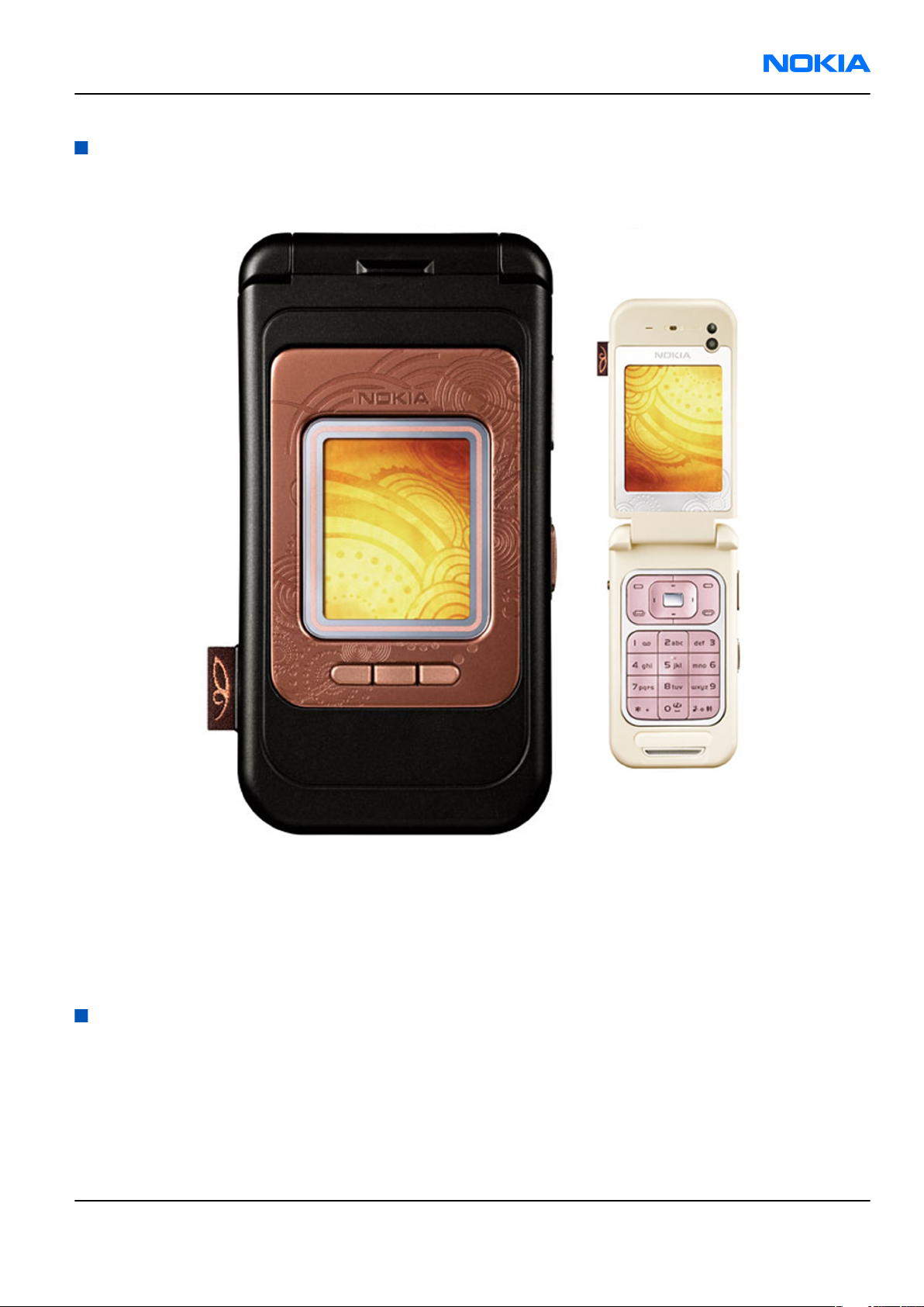
RM-140 (Nokia 7390)
Mobile Terminal
Part No: 9250831 (Issue 1)
COMPANY CONFIDENTIAL
Copyright © 2006 Nokia. All rights reserved.
Page 2

RM-140
Nokia Customer Care Amendment Record Sheet
Amendment Record Sheet
Amendment No Date Inserted By Comments
Original issue 10/2006 J Bryman
Page ii COMPANY CONFIDENTIAL Issue 1
Copyright © 2006 Nokia. All rights reserved.
Page 3

RM-140
Copyright Nokia Customer Care
Copyright
Copyright © 2006 Nokia. All rights reserved.
Reproduction, transfer, distribution or storage of part or all of the contents in this document in any form
without the prior written permission of Nokia is prohibited.
Nokia, Nokia Connecting People, and Nokia X and Y are trademarks or registered trademarks of Nokia
Corporation. Other product and company names mentioned herein may be trademarks or tradenames of
their respective owners.
Nokia operates a policy of continuous development. Nokia reserves the right to make changes and
improvements to any of the products described in this document without prior notice.
Under no circumstances shall Nokia be responsible for any loss of data or income or any special, incidental,
consequential or indirect damages howsoever caused.
The contents of this document are provided "as is". Except as required by applicable law, no warranties of
any kind, either express or implied, including, but not limited to, the implied warranties of merchantability
and fitness for a particular purpose, are made in relation to the accuracy, reliability or contents of this
document. Nokia reserves the right to revise this document or withdraw it at any time without prior notice.
The availability of particular products may vary by region.
IMPORTANT
This document is intended for use by qualified service personnel only.
Issue 1 COMPANY CONFIDENTIAL Page iii
Copyright © 2006 Nokia. All rights reserved.
Page 4

RM-140
Nokia Customer Care Warnings and cautions
Warnings and cautions
Warnings
• IF THE DEVICE CAN BE INSTALLED IN A VEHICLE, CARE MUST BE TAKEN ON INSTALLATION IN VEHICLES FITTED
WITH ELECTRONIC ENGINE MANAGEMENT SYSTEMS AND ANTI-SKID BRAKING SYSTEMS. UNDER CERTAIN FAULT
CONDITIONS, EMITTED RF ENERGY CAN AFFECT THEIR OPERATION. IF NECESSARY, CONSULT THE VEHICLE DEALER/
MANUFACTURER TO DETERMINE THE IMMUNITY OF VEHICLE ELECTRONIC SYSTEMS TO RF ENERGY.
• THE PRODUCT MUST NOT BE OPERATED IN AREAS LIKELY TO CONTAIN POTENTIALLY EXPLOSIVE ATMOSPHERES,
FOR EXAMPLE, PETROL STATIONS (SERVICE STATIONS), BLASTING AREAS ETC.
• OPERATION OF ANY RADIO TRANSMITTING EQUIPMENT, INCLUDING CELLULAR TELEPHONES, MAY INTERFERE
WITH THE FUNCTIONALITY OF INADEQUATELY PROTECTED MEDICAL DEVICES. CONSULT A PHYSICIAN OR THE
MANUFACTURER OF THE MEDICAL DEVICE IF YOU HAVE ANY QUESTIONS. OTHER ELECTRONIC EQUIPMENT MAY
ALSO BE SUBJECT TO INTERFERENCE.
• BEFORE MAKING ANY TEST CONNECTIONS, MAKE SURE YOU HAVE SWITCHED OFF ALL EQUIPMENT.
Cautions
• Servicing and alignment must be undertaken by qualified personnel only.
• Ensure all work is carried out at an anti-static workstation and that an anti-static wrist strap is worn.
• Ensure solder, wire, or foreign matter does not enter the telephone as damage may result.
• Use only approved components as specified in the parts list.
• Ensure all components, modules, screws and insulators are correctly re-fitted after servicing and
alignment.
• Ensure all cables and wires are repositioned correctly.
• Never test a mobile phone WCDMA transmitter with full Tx power, if there is no possibility to perform the
measurements in a good performance RF-shielded room. Even low power WCDMA transmitters may disturb
nearby WCDMA networks and cause problems to 3G cellular phone communication in a wide area.
• During testing never activate the GSM or WCDMA transmitter without a proper antenna load, otherwise
GSM or WCDMA PA may be damaged.
Page iv COMPANY CONFIDENTIAL Issue 1
Copyright © 2006 Nokia. All rights reserved.
Page 5

RM-140
For your safety Nokia Customer Care
For your safety
QUALIFIED SERVICE
Only qualified personnel may install or repair phone equipment.
ACCESSORIES AND BATTERIES
Use only approved accessories and batteries. Do not connect incompatible products.
CONNECTING TO OTHER DEVICES
When connecting to any other device, read its user’s guide for detailed safety instructions. Do not connect
incompatible products.
Issue 1 COMPANY CONFIDENTIAL Page v
Copyright © 2006 Nokia. All rights reserved.
Page 6

RM-140
Nokia Customer Care Care and maintenance
Care and maintenance
This product is of superior design and craftsmanship and should be treated with care. The suggestions below
will help you to fulfil any warranty obligations and to enjoy this product for many years.
• Keep the phone and all its parts and accessories out of the reach of small children.
• Keep the phone dry. Precipitation, humidity and all types of liquids or moisture can contain minerals that
will corrode electronic circuits.
• Do not use or store the phone in dusty, dirty areas. Its moving parts can be damaged.
• Do not store the phone in hot areas. High temperatures can shorten the life of electronic devices, damage
batteries, and warp or melt certain plastics.
• Do not store the phone in cold areas. When it warms up (to its normal temperature), moisture can form
inside, which may damage electronic circuit boards.
• Do not drop, knock or shake the phone. Rough handling can break internal circuit boards.
• Do not use harsh chemicals, cleaning solvents, or strong detergents to clean the phone.
• Do not paint the phone. Paint can clog the moving parts and prevent proper operation.
• Use only the supplied or an approved replacement antenna. Unauthorised antennas, modifications or
attachments could damage the phone and may violate regulations governing radio devices.
All of the above suggestions apply equally to the product, battery, charger or any accessory.
Page vi COMPANY CONFIDENTIAL Issue 1
Copyright © 2006 Nokia. All rights reserved.
Page 7

RM-140
ESD protection Nokia Customer Care
ESD protection
Nokia requires that service points have sufficient ESD protection (against static electricity) when servicing
the phone.
Any product of which the covers are removed must be handled with ESD protection. The SIM card can be
replaced without ESD protection if the product is otherwise ready for use.
To replace the covers ESD protection must be applied.
All electronic parts of the product are susceptible to ESD. Resistors, too, can be damaged by static electricity
discharge.
All ESD sensitive parts must be packed in metallized protective bags during shipping and handling outside
any ESD Protected Area (EPA).
Every repair action involving opening the product or handling the product components must be done under
ESD protection.
ESD protected spare part packages MUST NOT be opened/closed out of an ESD Protected Area.
For more information and local requirements about ESD protection and ESD Protected Area, contact your local
Nokia After Market Services representative.
Issue 1 COMPANY CONFIDENTIAL Page vii
Copyright © 2006 Nokia. All rights reserved.
Page 8

RM-140
Nokia Customer Care Battery information
Battery information
Note: A new battery's full performance is achieved only after two or three complete charge and
discharge cycles!
The battery can be charged and discharged hundreds of times but it will eventually wear out. When the
operating time (talk-time and standby time) is noticeably shorter than normal, it is time to buy a new battery.
Use only batteries approved by the phone manufacturer and recharge the battery only with the chargers
approved by the manufacturer. Unplug the charger when not in use. Do not leave the battery connected to
a charger for longer than a week, since overcharging may shorten its lifetime. If left unused a fully charged
battery will discharge itself over time.
Temperature extremes can affect the ability of your battery to charge.
For good operation times with Ni-Cd/NiMh batteries, discharge the battery from time to time by leaving the
product switched on until it turns itself off (or by using the battery discharge facility of any approved accessory
available for the product). Do not attempt to discharge the battery by any other means.
Use the battery only for its intended purpose.
Never use any charger or battery which is damaged.
Do not short-circuit the battery. Accidental short-circuiting can occur when a metallic object (coin, clip or
pen) causes direct connection of the + and - terminals of the battery (metal strips on the battery) for example
when you carry a spare battery in your pocket or purse. Short-circuiting the terminals may damage the battery
or the connecting object.
Leaving the battery in hot or cold places, such as in a closed car in summer or winter conditions, will reduce
the capacity and lifetime of the battery. Always try to keep the battery between 15°C and 25°C (59°F and 77°
F). A phone with a hot or cold battery may temporarily not work, even when the battery is fully charged.
Batteries' performance is particularly limited in temperatures well below freezing.
Do not dispose of batteries in a fire!
Dispose of batteries according to local regulations (e.g. recycling). Do not dispose as household waste.
Page viii COMPANY CONFIDENTIAL Issue 1
Copyright © 2006 Nokia. All rights reserved.
Page 9

RM-140
Company Policy Nokia Customer Care
Company Policy
Our policy is of continuous development; details of all technical modifications will be included with service
bulletins.
While every endeavour has been made to ensure the accuracy of this document, some errors may exist. If
any errors are found by the reader, NOKIA MOBILE PHONES Business Group should be notified in writing/email.
Please state:
• Title of the Document + Issue Number/Date of publication
• Latest Amendment Number (if applicable)
• Page(s) and/or Figure(s) in error
Please send to:
NOKIA CORPORATION
Nokia Mobile Phones Business Group
Nokia Customer Care
PO Box 86
FIN-24101 SALO
Finland
E-mail: Service.Manuals@nokia.com
Issue 1 COMPANY CONFIDENTIAL Page ix
Copyright © 2006 Nokia. All rights reserved.
Page 10

RM-140
Nokia Customer Care Company Policy
(This page left intentionally blank.)
Page x COMPANY CONFIDENTIAL Issue 1
Copyright © 2006 Nokia. All rights reserved.
Page 11

RM-140
Nokia 7390 Service Manual Structure Nokia Customer Care
Nokia 7390 Service Manual Structure
1 General information
2 Parts and layouts
3 Service Software Instructions
4 Service Tools and Service Concepts
5 Disassembly and reassembly instructions
6 BB Troubleshooting and Manual Tuning Guide
7 RF troubleshooting
8 System Module
9 Schematics
Glossary
Issue 1 COMPANY CONFIDENTIAL Page xi
Copyright © 2006 Nokia. All rights reserved.
Page 12

RM-140
Nokia Customer Care Nokia 7390 Service Manual Structure
(This page left intentionally blank.)
Page xii COMPANY CONFIDENTIAL Issue 1
Copyright © 2006 Nokia. All rights reserved.
Page 13

Nokia Customer Care
1 — General information
Issue 1 COMPANY CONFIDENTIAL Page 1 –1
Copyright © 2006 Nokia. All rights reserved.
Page 14

RM-140
Nokia Customer Care General information
(This page left intentionally blank.)
Page 1 –2 COMPANY CONFIDENTIAL Issue 1
Copyright © 2006 Nokia. All rights reserved.
Page 15

RM-140
General information Nokia Customer Care
Table of Contents
Product selection....................................................................................................................................................1–5
Phone features........................................................................................................................................................1–5
Software and User interface features...................................................................................................................1–6
Accessories..............................................................................................................................................................1–7
Specifications..........................................................................................................................................................1–9
General specifications.......................................................................................................................................1–9
Battery endurance.............................................................................................................................................1–9
List of Tables
Table 1 Battery and chargers................................................................................................................................1–8
Table 2 Car accessories..........................................................................................................................................1–8
Table 3 Headsets.....................................................................................................................................................1–8
Table 4 Memory......................................................................................................................................................1–9
Issue 1 COMPANY CONFIDENTIAL Page 1 –3
Copyright © 2006 Nokia. All rights reserved.
Page 16

RM-140
Nokia Customer Care General information
(This page left intentionally blank.)
Page 1 –4 COMPANY CONFIDENTIAL Issue 1
Copyright © 2006 Nokia. All rights reserved.
Page 17
RM-140
General information Nokia Customer Care
Product selection
RM-140 (Nokia 7390) is a WCDMA/GSM dual mode phone, supporting WCDMA 2100 (UMTS) and
EGSM900/1800/1900 bands.
Key Features:
• Fold design
• 2 displays; one main and one small
• 3 megapixel camera with autofocus and integrated flash
• VGA camera for video calls
Phone features
Display and keypad features
• QVGA main display in 16 million colors
• 160 x 128 pixels mini display in 262,144 colors
• Side volume keys with zoom functionality
• Dedicated camera key with autofocus
Issue 1 COMPANY CONFIDENTIAL Page 1 –5
Copyright © 2006 Nokia. All rights reserved.
Page 18
RM-140
Nokia Customer Care General information
• Power on/off key
Hardware features
• 3-megapixel camera landscape mode and 8x digital zoom
• VGA camera for video calls
• Mini USB port
• AV connector
• 2 mm charger plug interface
• Bluetooth
• USB
• FM radio
• MP3 player
• Internal vibrator
• Plug-in SIM (1.8 V and 3.0 V)
• Real time clock
RF features
• WCDMA 2100
• GSM/EDGE 900/1800/1900
• EDGE: Class 11
• GPRS: Class 11
• HSCSD
• CSD
Software and User interface features
Software features
• ISA OS 8.0s Platform
• Series 40 3rd edition User Interface (UI): Java MIDP 2.0
UI features
Imaging • 3 megapixel camera with autofocus
• 3GPP H.263 playback and streaming
Multimedia • Playback for the following video formats: 3GPP, H.263 video, MPEG-4
• Integrated FM radio
• Integrated music player for MP3/AAC/M4A/eAAC+/AAC+ formats
Memory functions • 128 MB memory card
• Options to expand memory up to 2 GB with microSD card
Page 1 –6 COMPANY CONFIDENTIAL Issue 1
Copyright © 2006 Nokia. All rights reserved.
Page 19
RM-140
General information Nokia Customer Care
Messaging • Multimedia messaging: MMS for creating, receiving, editing, and sending
videos and pictures with AMR voice clips
• Email: Supports SMTP, POP3, IMAP4, and APOP protocols. Support for
attachments (view jpeg, 3gp, MP3, .ppt, .doc, excel, and .pdf files)
• Text messaging: Supports concatenated SMS, picture messaging, SMS
distribution list
• Presence-enhanced contacts: Check the online status of your friends
before you call them
• Audio messaging: Record your own voice message and send to
compatible devices
• Nokia Xpress audio messaging: Send a spontaneously recorded voice clip
via MMS
• Instant Messaging and Presence-enhanced contacts
Games Music quiz, Snake, 3D race game
Java applications Java & APIs: MIDP2.0, JSR139 (CLDC1.1), JSR75 (file connection and PIM),
JSR135, JSR184 (3D), JSR82 (BT)
Ringing tones • Supported file formats: MP3, MPEG4, AAC, eAAC+, WMA files and AMR voice,
64-chord/voice polyphonic MIDI ringing tones
• Video ringtones
Connectivity • Bluetooth
• Infrared (IR)
Browsing WAP* 2.0, XHTML browser over HTTP/TCP/IP stack
Data transfer • EDGE (EGPRS): MSC 11 (RX+TX 4+3, 3+2) (max 5 slots)
• GPRS: MSC 11 (RX+TX: 4+3, 3+2) (max 5 slots)
• HSCSD (High-Speed Circuit-Switched Data)* / CSD (Circuit-Switched Data)
Digital services Music and video streaming services
Voice features • Voice dialing
• Voice commands
• Voice recorder
Personal Information
Management (PIM)
• Alarm clock
• Stopwatch
• Calculator
• Calendar
Other features Internal antenna
Accessories
Sales package contents
• Nokia 7390 phone
• Nokia Battery BP-5M
• Nokia Standard Charger AC-3
Issue 1 COMPANY CONFIDENTIAL Page 1 –7
Copyright © 2006 Nokia. All rights reserved.
Page 20

RM-140
Nokia Customer Care General information
• Nokia Headset HS-60
• Nokia Connectivity Cable DKE-2
• User Guide
Table 1 Battery and chargers
Type Name
Note: This phone is charged through the smaller Nokia standard interface (2.0 mm plug). The 3.5 mm
standard charger can be used together with the CA-44 charger adapter.
AC-3 Compact charger
AC-4 Travel performance charger
BP-5M Battery 900 mAh Li-Ion
CA-44 Charger adapter (from 3.5 mm -> 2 mm)
Table 2 Car accessories
Type Name
HF-6W Wireless plug-in handsfree
CK-1W Wireless car kit
CK-7W Advanced Car Kit
DC-4 Mobile charger
N616 Car kit
Table 3 Headsets
Type Name
HDW-3 Wireless headset
HS-11W Wireless headset
HS-12W Wireless headset
HS-13W Wireless headset
HS-21W Wireless clip-on headset
HS-24W Wireless headset
HS-25W Wireless headset
HS-26W Wireless headset
HS-34W Wireless stereo headset
HS-36W Wireless headset
HS-37W Wireless headset
HS-39W Wireless stereo headset
HS-40 Headset (wired)
HS-47 Stereo headset (wired)
Page 1 –8 COMPANY CONFIDENTIAL Issue 1
Copyright © 2006 Nokia. All rights reserved.
Page 21
RM-140
General information Nokia Customer Care
Type Name
HS-4W Wireless boom headset
HS-50W Wireless headset
HS-51W Wireless headset
HS-52W Wireless headset
HS-57W Wireless headset
HS-58W Wireless headset
HS-59W Wireless headset
HS-60 Fashion stereo headset (wired)
Table 4 Memory
Type Name
DKE-2 USB cable
MU-22 1 GB µSD card
MU-26 128 MB µSD card
MU-27 256 MB µSD card
MU-28 512 MB µSD card
MU-37 2 GB µSD card
Specifications
General specifications
Unit Dimension (mm) Weight (g) Volume (cc)
RM-140 Transceiver
with BP-5M 900 mAh LiIon battery pack
90 x 47 x 10 115 78
Battery endurance
Battery Talk time Standby time
BP-5M 900 mAh Li-ion GSM: up to 3 hours
WCDMA: up to 2.5 hours
Up to 220 hours
Note: Variation in operation times will occur depending on SIM card, network settings and usage.
Talk time is increased by up to 30% if half rate is active, and reduced by 5% if enhanced full rate is
active.
Issue 1 COMPANY CONFIDENTIAL Page 1 –9
Copyright © 2006 Nokia. All rights reserved.
Page 22

RM-140
Nokia Customer Care General information
(This page left intentionally blank.)
Page 1 –10 COMPANY CONFIDENTIAL Issue 1
Copyright © 2006 Nokia. All rights reserved.
Page 23

Nokia Customer Care
2 — Parts and layouts
Issue 1 COMPANY CONFIDENTIAL Page 2 –1
Copyright © 2006 Nokia. All rights reserved.
Page 24

RM-140
Nokia Customer Care Parts and layouts
(This page left intentionally blank.)
Page 2 –2 COMPANY CONFIDENTIAL Issue 1
Copyright © 2006 Nokia. All rights reserved.
Page 25

RM-140
Parts and layouts Nokia Customer Care
Table of Contents
Exploded view.........................................................................................................................................................2–5
Spare parts overview.............................................................................................................................................2–6
Mechanical parts list...............................................................................................................................................2–7
Swap units...............................................................................................................................................................2–8
Component parts list............................................................................................................................................2–10
Component layouts..............................................................................................................................................2–22
List of Tables
Table 5 Mechanical parts list.................................................................................................................................2–7
Table 6 Swap phones.............................................................................................................................................2–8
Table 7 Light swap.................................................................................................................................................2–9
Table 8 Replaceable component parts...............................................................................................................2–10
List of Figures
Figure 1 Main board layout, top side (1tma_12a).............................................................................................2–22
Figure 2 Main board layout, bottom side (1tma_12a)......................................................................................2–23
Figure 3 Top board layout, top side (1tmb_04a)..............................................................................................2–23
Figure 4 Top board layout, bottom side (1tmb_04a).......................................................................................2–24
Issue 1 COMPANY CONFIDENTIAL Page 2 –3
Copyright © 2006 Nokia. All rights reserved.
Page 26

RM-140
Nokia Customer Care Parts and layouts
(This page left intentionally blank.)
Page 2 –4 COMPANY CONFIDENTIAL Issue 1
Copyright © 2006 Nokia. All rights reserved.
Page 27
RM-140
Parts and layouts Nokia Customer Care
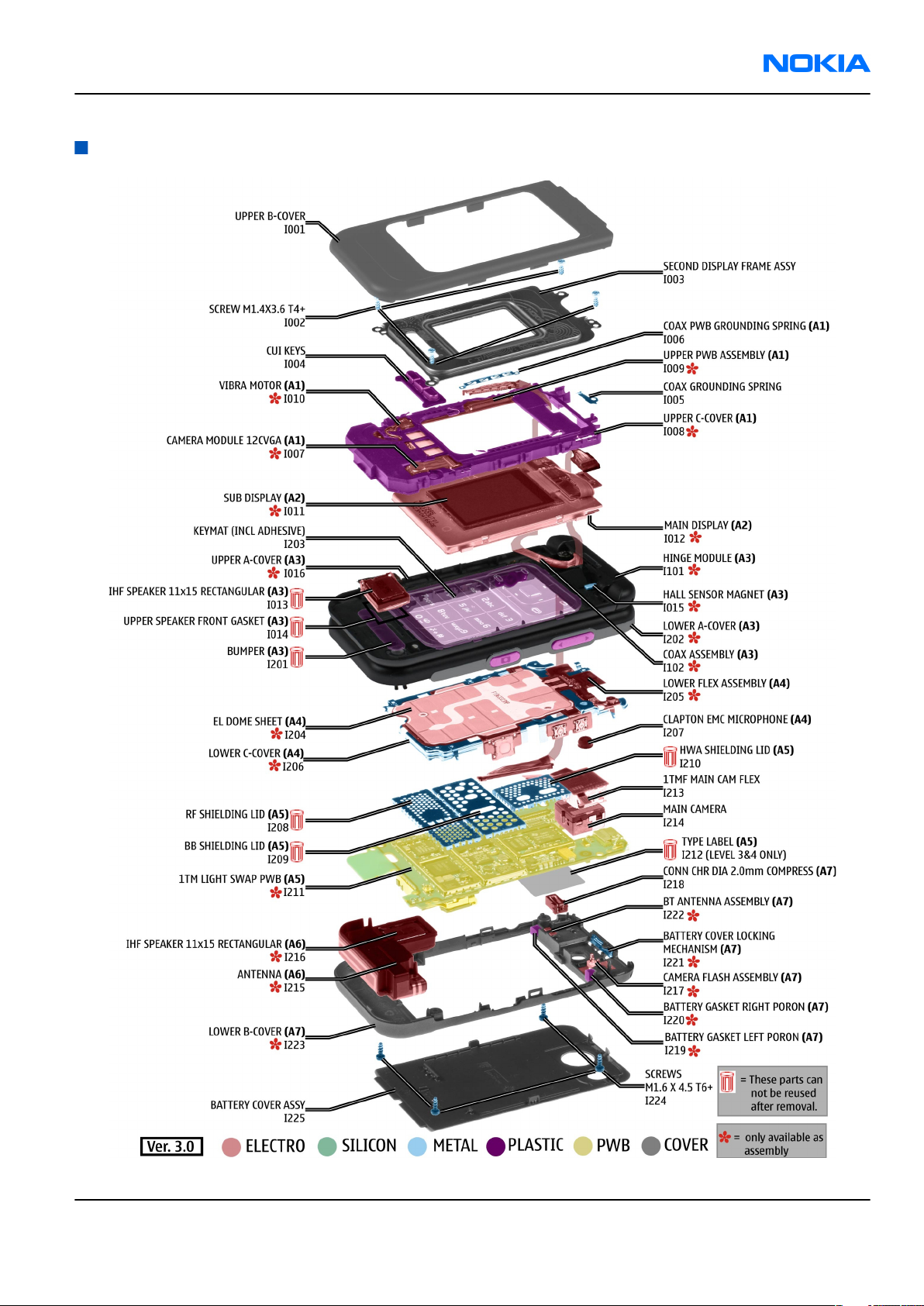
Exploded view
Issue 1 COMPANY CONFIDENTIAL Page 2 –5
Copyright © 2006 Nokia. All rights reserved.
Page 28
RM-140
Nokia Customer Care Parts and layouts
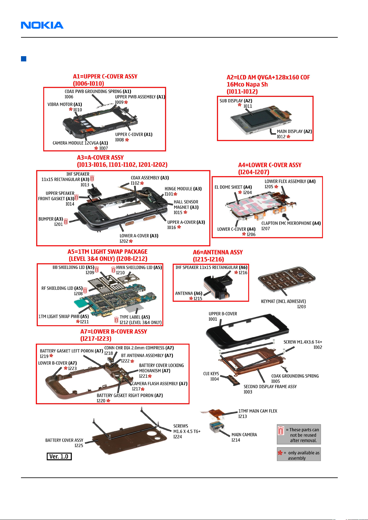
Spare parts overview
Page 2 –6 COMPANY CONFIDENTIAL Issue 1
Copyright © 2006 Nokia. All rights reserved.
Page 29
RM-140
Parts and layouts Nokia Customer Care
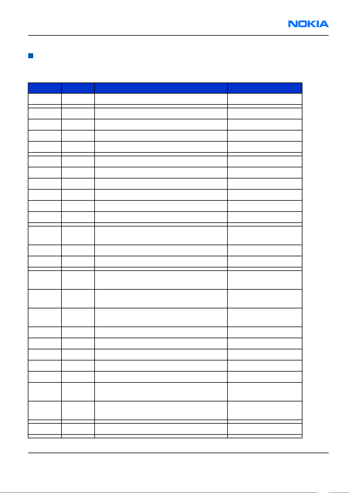
Mechanical parts list
Table 5 Mechanical parts list
Note: For product codes and variants, please refer to the latest Service bulletin.
ITEM QTY PART NAME Comment
I001 1 UPPER B-COVER Assembly
I002 4 SCREWS M1.4 X 3.6 T4+
I003 1 SECOND DISPLAY FRAME ASSY
I004 1 CUI keys
I005 1 COAX GROUNDING SPRING
A1 1 UPPER C-COVER ASSY(I006-I010)
I006 1 COAX PWB GROUNDING SPRING
I007 1 CAMERA MOD 12C VGA
I008 1 UPPER C-COVER
I009 1 UPPER PWB ASSEMBLY
I010 1 VIBRA MOTOR
A2 1
LCD AM QVGA+128x160 COF 16Mco Napa Sh
(I011-I012)
I011 1 SUB DISPLAY
I012 1 MAIN DISPLAY
A3 1
A-COVER ASSY(I013-I016, I101-I102, I201-
I202)
I013 1 IHF SPEAKER 11x15 RECTANGULAR
I014 UPPER SPEAKER FRONT GASKET
I015 1 HALL SENSOR MAGNET
I016 1 UPPER A-COVER
I101 1 HINGE MODULE
Must be replaced after
disassembly
Must be replaced after
disassembly
I102 1 COAX ASSEMBLY
I201 1 BUMPER BLACK
Must be replaced after
I201 1 BUMPER WHITE
disassembly
Must be replaced after
I202 1 LOWER A-COVER
disassembly
I203 1 Keymat Assembly
Issue 1 COMPANY CONFIDENTIAL Page 2 –7
Copyright © 2006 Nokia. All rights reserved.
Page 30
RM-140
Nokia Customer Care Parts and layouts
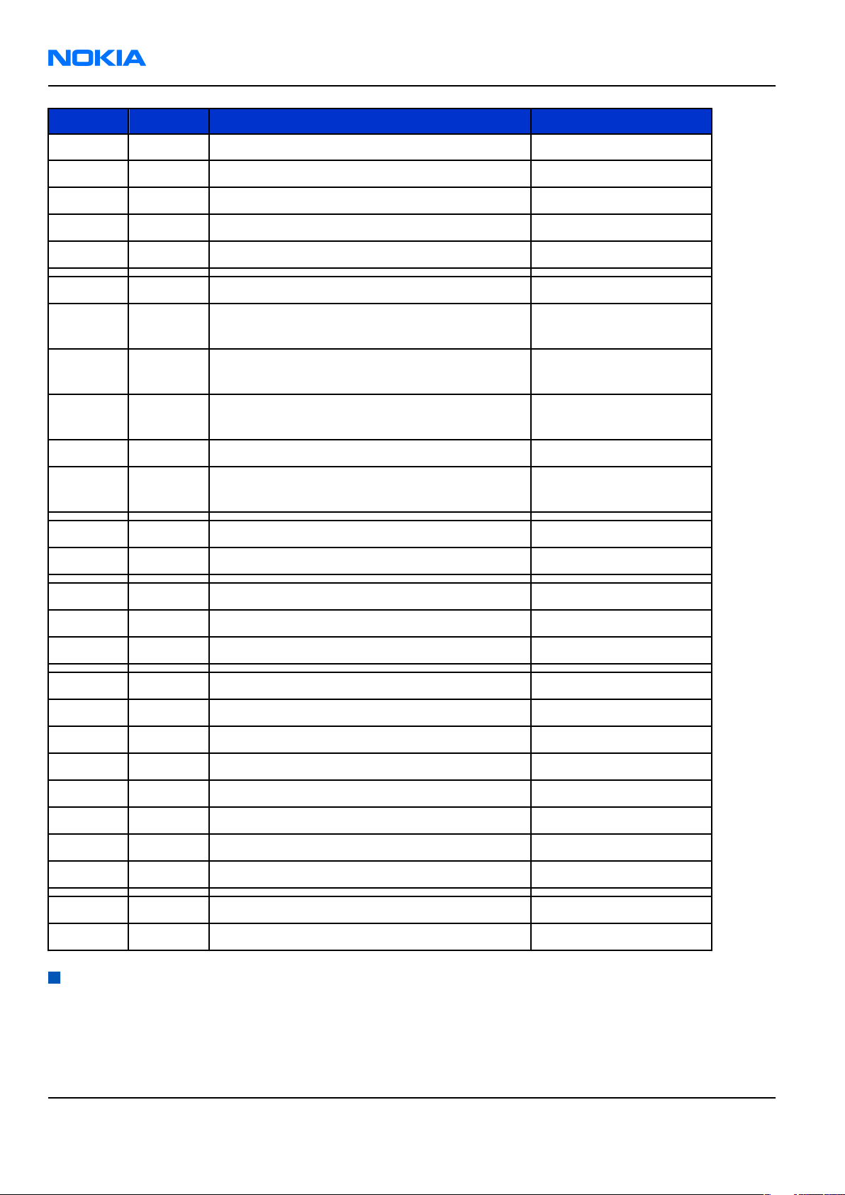
ITEM QTY PART NAME Comment
A4 1 LOWER C-COVER ASSY(I204 - I207)
I204 1 EL DOME SHEET
I205 1 LOWER FLEX ASSEMBLY
I206 1 LOWER C-COVER
I207 1 CLAPTON EMC MICROPHONE
A5 1 1TM LIGHT SWAP PACKAGE(I208 - I212)
Must be replaced after
I208 1 RF SHIELDING LID
disassembly
Must be replaced after
I209 1 BB SHIELDING LID
disassembly
Must be replaced after
I210 1 HWA SHIELDING LID
disassembly
I211 1 1TM LIGHT SWAP PWB
I212 1 TYPE LABEL
I213 1 1TMF MAIN CAM FLEX
I214 1 MAIN CAMERA
A6 1 ANTENNA ASSY(I215 - I216)
I215 1 ANTENNA
I216 1 IHF SPEAKER 11x15 RECTANGULAR
A7 1 LOWER B-COVER ASSY(I217 - I223)
I217 1 CAMERA FLASH ASSEMBLY
I218 1 CONN CHR DIA 2.0MM COMPRESS
I219 1 BATTERY GASKET LEFT PORON
I220 1 BATTERY GASKET RIGHT PORON
I221 1 BATTERY COVER LOCKING MECHANISM
I222 1 BT ANTENNA ASSEMBLY
I223 1 LOWER B-COVER
Must be replaced after
disassembly
I224 4 SCREWS M1.6 X 4.5 T6+
I225 1 Battery cover assembly
Swap units
Table 6 Swap phones
Note: For product codes, please refer to the latest Service bulletin.
Page 2 –8 COMPANY CONFIDENTIAL Issue 1
Copyright © 2006 Nokia. All rights reserved.
Page 31

RM-140
Parts and layouts Nokia Customer Care
Swap phones
N7390 RM-140 SWAP PHONE E&A BLACK BRONZE
N7390 RM-140 SWAP PHONE RSA BLACK BRONZE
N7390 RM-140 SWAP PHONE FRA BLACK BRONZE
N7390 RM-140 SWAP PHONE TUR BLACK BRONZE
N7390 RM-140 SWAP PHONE ISR BLACK BRONZE
N7390 RM-140 SWAP PHONE UAE BLACK BRONZE
N7390 RM-140 SWAP PHONE RUS BLACK BRONZE
N7390 RM-140 SWAP PHONE UKR BLACK BRONZE
N7390 RM-140 SWAP PHONE BLR BLACK BRONZE
N7390 RM-140 SWAP PHONE E&A POWDER PINK
N7390 RM-140 SWAP PHONE RSA POWDER PINK
N7390 RM-140 SWAP PHONE FRA POWDER PINK
N7390 RM-140 SWAP PHONE TUR POWDER PINK
N7390 RM-140 SWAP PHONE ISR POWDER PINK
N7390 RM-140 SWAP PHONE UAE POWDER PINK
N7390 RM-140 SWAP PHONE GRE POWDER PINK
N7390 RM-140 SWAP PHONE RUS POWDER PINK
N7390 RM-140 SWAP PHONE UKR POWDER PINK
N7390 RM-140 SWAP PHONE BLR POWDER PINK
N7390 RM-140 SWAP PHONE GRE BLACK BRONZE
Table 7 Light swap
Note: For product codes, please refer to the latest Service bulletin.
Light swap
RM-140 LIGHT SWAP EURO-C
RM-140 LIGHT SWAP EURO-C FRANCE
RM-140 LIGHT SWAP EURO-C TURKEY
RM-140 LIGHT SWAP EURO-I BELARUS
RM-140 LIGHT SWAP EURO-I UKRANE
RM-140 LIGHT SWAP EURO-I RUSS
RM-140 LIGHT SWAP EURO-C MEA 13 SA
RM-140 LIGHT SWAP APAC-U TH
RM-140 LIGHT SWAP LATIN APAC-T PH
RM-140 LIGHT SWAP BOPO CHINA-P CTV_TW
Issue 1 COMPANY CONFIDENTIAL Page 2 –9
Copyright © 2006 Nokia. All rights reserved.
Page 32

RM-140
Nokia Customer Care Parts and layouts
Component parts list
Table 8 Replaceable component parts
Note: For product codes, please refer to the latest Service bulletin.
Item Side XY Object Name
A2200 T I5 BB SHIELD ASSEMBLY
A3300 T M5 HWA SHIELD ASSEMBLY
A7500 T F5 RF SHIELD ASSEMBLY
B2200 T J5 CRYSTAL 32.768KHZ +/-20PPM 12.5PF
C0001 CHIPCAP NP0 5P6 C 50V 0402
C2000 B O9 CHIPCAP NP0 27P J 50V 0402
C2002 T Q8 CHIPCAP NP0 27P J 50V 0402
C2003 B O9 CHIPCAP FEEDTHRU 100N M 25V 0805
C2004 T P8 CHIPCAP NETWORK X5R 2X1U5 K 6V3 0405
C2005 T Q8 CHIPCAP X5R 2U2 K 6V3 0603
C2006 T P8 CHIPCAP X5R 2U2 K 6V3 0603
C2007 T Q8 CHIPCAP X5R 2U2 K 6V3 0603
C2008 T Q7 CHIPCAP NP0 18P J 50V 0402
C2009 T Q7 CHIPCAP NP0 18P J 50V 0402
C2012 B O9 CHIPCAP X5R 470N K 25V 0603
C2013 T P7 CHIPCAP X7R 10N K 16V 0402
C2014 T O7 CHIPCAP X7R 10N K 16V 0402
C2070 T N2 CHIPTCAP 150U M 10V 6X3.2X1.5
C2106 T F9 CHIPCAP NP0 27P J 50V 0402
C2107 T G9 CHIPCAP NP0 27P J 50V 0402
C2111 T G9 CHIPCAP NP0 27P J 50V 0402
C2112 T H9 CHIPCAP NP0 27P J 50V 0402
C2117 T I9 CHIPCAP X5R 100N K 10V 0402
C2118 T I9 CHIPCAP X5R 100N K 10V 0402
C2119 T I9 CHIPCAP X5R 100N K 10V 0402
C2120 T I9 CHIPCAP X5R 100N K 10V 0402
C2124 T I9 CHIPCAP X5R 100N K 10V 0402
C2126 T I9 CHIPCAP X5R 10U M 6V3 0805
C2127 T I9 CHIPCAP X5R 1U K 6V3 0603
C2170 T H1 CHIPCAP X7R 1N0 K 50V 0402
C2171 T H1 CHIPCAP X7R 1N0 K 50V 0402
Page 2 –10 COMPANY CONFIDENTIAL Issue 1
Copyright © 2006 Nokia. All rights reserved.
Page 33

RM-140
Parts and layouts Nokia Customer Care
Item Side XY Object Name
C2172 T H1 CHIPCAP X7R 1N0 K 50V 0402
C2201 T I5 CHIPCAP X5R 1U5 K 4V 0402
C2202 T H4 CHIPCAP X5R 2U2 K 6V3 0603
C2203 T I4 CHIPCAP X5R 2U2 K 6V3 0603
C2205 T I4 CHIPCAP X7R 1N0 J 50V 0402
C2211 T H5 CHIPCAP X5R 4U7 K 10V 0805
C2213 T I5 CHIPCAP NETWORK X5R 2X1U5 K 6V3 0405
C2215 T I5 CHIPCAP NETWORK X5R 2X1U5 K 6V3 0405
C2216 T J5 CHIPCAP X5R 1U5 K 4V 0402
C2217 T I4 CHIPCAP X5R 1U5 K 4V 0402
C2220 T H4 CHIPCAP NETWORK X5R 2X1U5 K 6V3 0405
C2222 T H5 CHIPCAP X5R 1U K 6V3 0603
C2225 T J5 CHIPCAP X5R 1U K 6V3 0603
C2226 T H5 CHIPCAP X5R 1U K 6V3 0603
C2227 T I5 CHIPCAP NETWORK X5R 2X1U5 K 6V3 0405
C2228 T H5 CHIPCAP NETWORK X5R 2X1U5 K 6V3 0405
C2231 T H4 CHIPCAP X5R 10UF 6V3 0603
C2232 T H5 CHIPCAP NETWORK X5R 2X1U5 K 6V3 0405
C2300 T H3 CHIPCAP X7R 10N K 16V 0402
C2301 T I2 CHIPCAP X5R 22U M 6V3 0805
C2302 T I2 CHIPCAP X5R 22U M 6V3 0805
C2303 T J2 CHIPCAP X5R 1U K 6V3 0603
C2304 T I2 CHIPCAP X7R 10N K 16V 0402
C2307 T J3 CHIPCAP X5R 1U K 6V3 0603
C2309 T H3 CHIPCAP X5R 22U M 6V3 0805
C2312 T J3 CHIPCAP NETWORK X5R 2X1U5 K 6V3 0405
C2314 T I3 CHIPCAP X5R 4U7 M 25V 0805
C2405 T K9 CHIPCAP X5R 1U K 6V3 0603
C2406 T K9 CHIPCAP X5R 1U K 6V3 0603
C2407 T L8 CHIPCAP NP0 27P J 50V 0402
C2408 T L8 CHIPCAP NP0 27P J 50V 0402
C2409 T M8 CHIPCAP NP0 27P J 50V 0402
C2550 CHIPCAP NP0 27P J 50V 0402
C2551 CHIPCAP X5R 1U K 6V3 0603
C2552 CHIPCAP NP0 56P J 50V 0402
Issue 1 COMPANY CONFIDENTIAL Page 2 –11
Copyright © 2006 Nokia. All rights reserved.
Page 34

RM-140
Nokia Customer Care Parts and layouts
Item Side XY Object Name
C2553 CHIPCAP X7R 6N8 K 25V 0402
C2554 CHIPCAP X5R 1U K 6V3 0402
C2555 CHIPCAP X7R 2N2 J 50V 0402
C2556 CHIPCAP X7R 2N2 J 50V 0402
C2557 CHIPCAP X7R 2N2 J 50V 0402
C2558 CHIPCAP X7R 2N2 J 50V 0402
C2600 T E9 CHIPCAP X5R 4U7 K 10V 0805
C2601 T E9 CHIPCAP NP0 27P J 50V 0402
C2602 T E9 CHIPCAP X5R 100N K 10V 0402
C2700 B F6 CHIPCAP X5R 100N K 10V 0402
C2701 B F6 CHIPCAP NP0 27P J 50V 0402
C2702 B E6 CHIPCAP NP0 10P J 50V 0402
C2703 B E6 CHIPCAP NP0 10P J 50V 0402
C2704 B E3 CHIPCAP NP0 10P J 50V 0402
C2800 T I6 CHIPCAP X5R 100N K 16V 0402
C2801 T H8 CHIPCAP X5R 100N K 16V 0402
C2802 T H6 CHIPCAP X5R 100N K 16V 0402
C2803 T H8 CHIPCAP X5R 100N K 16V 0402
C2804 T H8 CHIPCAP X5R 100N K 16V 0402
C2805 T H6 CHIPCAP X5R 100N K 16V 0402
C2806 T I8 CHIPCAP X5R 100N K 16V 0402
C2807 T J7 CHIPCAP X5R 100N K 16V 0402
C2808 T I8 CHIPCAP X5R 100N K 16V 0402
C2809 T J6 CHIPCAP X5R 100N K 16V 0402
C2810 T J6 CHIPCAP X5R 100N K 16V 0402
C2811 T H8 CHIPCAP X5R 100N K 16V 0402
C2812 T J8 CHIPCAP X5R 100N K 16V 0402
C2813 T H6 CHIPCAP X5R 100N K 16V 0402
C2814 T H7 CHIPCAP X5R 100N K 16V 0402
C2815 T H8 CHIPCAP X5R 100N K 16V 0402
C2816 T H6 CHIPCAP X5R 100N K 16V 0402
C2817 T H8 CHIPCAP X5R 100N K 16V 0402
C2818 T J6 CHIPCAP X5R 100N K 16V 0402
C2819 T H8 CHIPCAP X5R 100N K 16V 0402
C2820 T I8 CHIPCAP X5R 100N K 16V 0402
Page 2 –12 COMPANY CONFIDENTIAL Issue 1
Copyright © 2006 Nokia. All rights reserved.
Page 35

RM-140
Parts and layouts Nokia Customer Care
Item Side XY Object Name
C2821 T J7 CHIPCAP X5R 100N K 16V 0402
C2822 T H6 CHIPCAP X5R 100N K 16V 0402
C2823 T J8 CHIPCAP X7R 1N0 J 50V 0402
C3100 T J8 CHIPCAP NP0 27P J 50V 0402
C3300 T O7 CHIP ARRAY X5R 2X1U (2x1U2) K 6V3 0405
C3302 T O7 CHIPCAP X5R 1U K 6V3 0603
C3303 T O8 CHIPCAP X5R 1U K 6V3 0603
C3304 T M8 CHIPCAP X5R 1U K 6V3 0603
C3305 T N8 CHIPCAP NP0 27P J 50V 0402
C3307 T K2 CHIPCAP NP0 27P J 50V 0402
C3308 T K3 CHIPCAP X5R 22U M 6V3 0805
C3309 T L2 CHIPCAP X5R 22U M 6V3 0805
C3310 T K2 CHIPCAP X5R 22U M 6V3 0805
C3311 T L2 CHIPCAP X5R 22U M 6V3 0805
C3312 T L3 CHIPCAP X7R 1N0 J 50V 0402
C3350 T J5 CHIPCAP X5R 1U K 6V3 0402
C3351 T J7 CHIPCAP X5R 1U K 6V3 0402
C3352 CHIPCAP X5R 1U K 6V3 0402
C3400 T M4 CHIPCAP X7R 10N K 16V 0402
C3401 T N4 CHIP ARRAY X5R 2X10N K 16V 0405
C3403 T M5 CHIPCAP X7R 10N K 16V 0402
C3404 T N5 CHIPCAP X7R 10N K 16V 0402
C3406 T O5 CHIPCAP X5R 1U K 6V3 0402
C3407 T O5 CHIPCAP X7R 10N K 16V 0402
C3410 T N6 CHIPCAP X7R 10N K 16V 0402
C3411 T K5 CHIPCAP X7R 10N K 16V 0402
C3412 T M6 CHIPCAP X7R 10N K 16V 0402
C3415 T M4 CHIP ARRAY X5R 2X10N K 16V 0405
C3416 T N4 CHIPCAP X7R 1N8 J 50V 0402
C3417 T L4 CHIPCAP X5R 10UF 6V3 0603
C3418 T L4 CHIPCAP X5R 4U7 K 6.3V 0603
C3419 T K5 CHIPCAP X5R 1U K 6V3 0603
C3420 T K4 CHIPCAP X7R 10N K 16V 0402
C3421 T K4 CHIPCAP X5R 4U7 K 6.3V 0603
C3422 T K4 CHIPCAP X5R 4U7 K 6.3V 0603
Issue 1 COMPANY CONFIDENTIAL Page 2 –13
Copyright © 2006 Nokia. All rights reserved.
Page 36

RM-140
Nokia Customer Care Parts and layouts
Item Side XY Object Name
C3424 T N6 CHIPCAP NP0 15P J 50V 0402
C3425 T N4 CHIPCAP X7R 330P J 50V 0402
C3428 T N6 CHIPCAP NP0 27P J 50V 0402
C3429 T N6 CHIPCAP NP0 27P J 50V 0402
C3500 T Q9 CHIPCAP NP0 1P8 C 50V 0402
C3501 T N8 CHIPCAP NP0 27P J 50V 0402
C3502 T N8 CHIPCAP NP0 27P J 50V 0402
C3503 T O8 CHIPCAP NP0 27P J 50V 0402
C3504 T O8 CHIPCAP NP0 27P J 50V 0402
C3505 T P8 CHIPCAP NP0 27P J 50V 0402
C4800 B F3 CHIPCAP X5R 100N K 16V 0402
C4801 B E3 CHIPCAP X5R 100N K 16V 0402
C4803 B E3 CHIPCAP X5R 100N K 16V 0402
C4805 B E6 CHIPCAP NP0 27P J 50V 0402
C4806 B E2 CHIPCAP X5R 2U2 K 6V3 0603
C4807 B F2 CHIPCAP X7R 33N K 10V 0402
C4808 B E2 CHIPCAP X5R 2U2 K 6V3 0603
C6000 T P3 CHIPCAP X5R 100N K 16V 0402
C6001 T P3 CHIPCAP X5R 100N K 16V 0402
C6002 T N3 CHIPCAP X5R 1U K 6V3 0603
C6003 T P4 CHIPCAP X5R 1U K 6V3 0603
C6004 T P4 CHIPCAP X5R 100N K 16V 0402
C6005 T Q2 CHIPCAP X5R 100N K 16V 0402
C6050 T M2 CHIPCAP X5R 1U K 6V3 0603
C6051 T M3 CHIPCAP X5R 1U K 6V3 0603
C6052 T M3 CHIPCAP NP0 15P J 50V 0402
C7507 T E7 CHIPCAP X7R 10N K 16V 0402
C7513 T F8 CHIPCAP X7R 4N7 K 25V 0402
C7518 T G7 CHIPCAP X5R 100N K 16V 0402
C7519 T F8 CHIPCAP X5R 1U5 K 4V 0402
C7520 T F8 CHIPCAP X7R 1N0 J 50V 0402
C7521 T G4 CHIPCAP NP0 3P3 C 50V 0402
C7523 T E4 CHIPCAP NP0 3P3 C 50V 0402
C7524 T G5 CHIPCAP NP0 1P8 C 50V 0402
C7525 T G5 CHIPCAP NP0 10P J 50V 0402
Page 2 –14 COMPANY CONFIDENTIAL Issue 1
Copyright © 2006 Nokia. All rights reserved.
Page 37

RM-140
Parts and layouts Nokia Customer Care
Item Side XY Object Name
C7543 T F3 CHIPCAP X5R 4U7 K 6.3V 0603
C7544 T F2 CHIPCAP X7R 22N K 16V 0402
C7545 T F2 CHIPCAP NP0 10P J 50V 0402
C7547 T F2 CHIPCAP X5R 10UF 6V3 0603
C7548 T F2 CHIPCAP X7R 8N2 K 16V 0402
C7549 T F3 CHIPCAP X7R 8N2 K 16V 0402
C7550 T F2 CHIPCAP X7R 1N0 J 50V 0402
C7553 T E3 CHIPCAP X7R 1N0 J 50V 0402
C7580 T G8 CHIPCAP X5R 100N K 16V 0402
C7581 T G8 CHIPCAP X5R 100N K 16V 0402
C7582 T G9 CHIPCAP X5R 100N K 16V 0402
C7583 T G8 CHIPCAP X5R 100N K 16V 0402
C7586 T G7 CHIPCAP NP0 10P J 50V 0402
C7587 T F7 CHIPCAP NP0 10P J 50V 0402
C7590 T E6 CHIPCAP X5R 10UF 6V3 0603
C7591 T E6 CHIPCAP X5R 10UF 6V3 0603
C7801 T C2 CHIPCAP NP0 10P J 50V 0402
D3400 T L5 SDRAM 4MX16 1.8V/1.8V FBGA60 PBFREE
D6000 T Q3 BTHFM1.0 LMBA48EBR2-080
F2000 B Q9 SM FUSE F 2.0A 32V 0603
G2200 T J4 RTC BACKUP CAPAC 311 SIZE FOR 2.6V 4UAH
G7501 T E8 VCTCXO 38.4MHZ 2.5V 2MA
L2001 T Q8 FERRITE BEAD 0.6R 600R/100MZ 0402
L2002 T Q7 CHIP BEAD ARRAY 2X600R 0405
L2003 T P7 CHIP COIL 68NH J Q12/100MHZ 0603
L2005 T P7 FERRITE BEAD 0.6R 600R/100MZ 0402
L2101 T G9 FERR.BEAD 220R/100M 2A 0R05 0603
L2102 T F9 CHIP COIL 30nH J Q65/500MHz 0805
L2103 T F9 CHIP COIL 30nH J Q65/500MHz 0805
L2104 T H9 FERR.BEAD 220R/100M 2A 0R05 0603
L2107 T H9 FERR.BEAD 220R/100M 2A 0R05 0603
L2110 T G9 FERR.BEAD 220R/100M 2A 0R05 0603
L2111 T H9 FERRITE BEAD 0.6R 600R/100MZ 0402
L2170 B J5 CHIP COIL 30nH J Q65/500MHz 0805
L2171 B J4 CHIP COIL 30nH J Q65/500MHz 0805
Issue 1 COMPANY CONFIDENTIAL Page 2 –15
Copyright © 2006 Nokia. All rights reserved.
Page 38

RM-140
Nokia Customer Care Parts and layouts
Item Side XY Object Name
L2172 T H1 CHIP COIL 33N J Q40/250MHZ 0603
L2173 T H1 CHIP COIL 33N J Q40/250MHZ 0603
L2202 T H4 FERR.BEAD 220R/100M 2A 0R05 0603
L2205 T H4 FERR.BEAD 220R/100M 2A 0R05 0603
L2211 T N3 FERR.BEAD 220R/100M 2A 0R05 0603
L2212 T O3 FERR.BEAD 220R/100M 2A 0R05 0603
L2301 T H3 FERR.BEAD 220R/100M 2A 0R05 0603
L2302 T H2 INDUCT WW 10U 0A65 0R35 4X4X1.2
L2304 T H3 CHOKE 22U M 0R7 0.35A 3.0X3.0X1.5
L2400 T K8 FERRITE BEAD 0.6R 600R/100MZ 0402
L2401 T L8 FERRITE BEAD 0.6R 600R/100MZ 0402
L2550 COIL 0.47MH 50MA 3.3X3.4X1.4MM
L3300 T O7 FERR.BEAD 220R/100M 2A 0R05 0603
L3301 T P7 FERR.BEAD 220R/100M 2A 0R05 0603
L3302 T M8 FERR.BEAD 220R/100M 2A 0R05 0603
L3303 T K2 CHOKE 4U7 0.86A 0R2 3X3X1.5
L3350 T J4 FERR.BEAD 240R/100M 0.4A 0R3 0402
L3351 B J7 FERR.BEAD 240R/100M 0.4A 0R3 0402
L3352 FERR.BEAD 240R/100M 0.4A 0R3 0402
L3400 T M4 FERRITE BEAD 220R 0R45 0.3A 0402
L3401 T M4 FERRITE BEAD 220R 0R45 0.3A 0402
L3402 T K5 FERR.BEAD 220R/100M 2A 0R05 0603
L3403 T L4 INDUCT WW 2.2UH 1A2 310 case size
L3404 T M4 INDUCT WW 2.2UH 1A2 310 case size
L3405 T N4 CHIP COIL 120NH J Q8/100MHZ 0402
L3500 T Q8 CHIP COIL 68N J Q17/300MHZ 0402
L7500 T F7 CHIP COIL 12N J Q31/800MHZ 0402
L7501 T F7 CHIP COIL 12N J Q31/800MHZ 0402
L7502 T E7 FERR.BEAD 220R/100M 2A 0R05 0603
L7503 T G7 FERR.BEAD 240R/100M 0.4A 0R4 0402
L7506 T E8 FERR.BEAD 240R/100M 0.4A 0R4 0402
L7510 T E4 FERRITE BEAD 0R01 28R/100MHZ 0603
L7526 T G6 FERR.BEAD 240R/100M 0.4A 0R4 0402
L7540 T G3 CHOKE 3U3 1.2A 0R096 3X3X1.5
L7550 T F2 FERR.BEAD 240R/100M 0.4A 0R4 0402
Page 2 –16 COMPANY CONFIDENTIAL Issue 1
Copyright © 2006 Nokia. All rights reserved.
Page 39
RM-140
Parts and layouts Nokia Customer Care
Item Side XY Object Name
L7588 T E7 CHIP COIL 12N J Q31/800MHZ 0402
L7589 T E7 CHIP COIL 6N8 J Q27/800MHZ 0402
L7590 T E6 INDUCT ML CHIP PWR 3U3 M 0R15 0.2A
L7591 T G2 FERRITE BEAD 0R01 28R/100MHZ 0603
L7802 T C2 CHIP COIL 8N2 G Q80/800MHZ 0603
L7803 T C2 CHIP COIL 15N +-2% Q40/250MHz 0603
N2000 T Q8 ST HEADPHONE AMPLIFIER LM4920 uSMD14
N2001 T P8 IC ANALOG SWITCH SPDT LOW THRESHOLD CSP8
N2101 T H9 AF AMP TPA2012D2 77DB/217HZ WCSP16
N2160 T M7 TI ANALOG SWITCH TS5A3159AYZTR WCSP06
N2161 T M7 TI ANALOG SWITCH TS5A3159AYZTR WCSP06
N2200 T I5 AVILMA 1.05C BB MODULE TFBGA105
N2300 T I2 BETTY v2.1 LF TFBGA64
N2301 T H3 WHITE LED DRIVER 4LEDS 500mW 8bump USMD8
N2550 HALL IC SWITCH SH248CSP VCC
N2551 EL DRIVER D381B 2-7V MSOP-10
N2600 B F9 IRDA Mir Xsmall
N3300 T O7 VREG 2.85/150MA(LP3987-2.85)USMD5
N3301 T K3 DC/DC BOOST CONV. TPS61058 QFN-10
N3401 T L4 DC/DC CONV LM3671TLX-1.82V
N3402 T K4 DC/DC CONV TPS62311YZD 1.5V CSP8
N4800 B E3 LEVEL SHIFTER SINGLE SD/SDIO/MMC CSP25
N4801 B E2 LI VREG 3.0V/300mA (LP3981YD-3.0) LLP6
N6050 T M3 VREG 2.85/150MA(LP3987-2.85)USMD5
N7505 T F8 AHNEUS203A TFBGA144
N7520 T F5 PW AMP GSM/EDGE850/900/1800/1900 8x8x1.3
N7541 T G2 DC CONV LM3202TLX NOPB revB µSMD8
N7590 T E6 DC CONV LM3202TLX NOPB revB µSMD8
R2001 T O7 CHIPRES 0W06 100K J 0402
R2002 T P7 CHIP VARISTOR VWM14V VC50V 0402
R2003 T Q8 CHIP VARISTOR VWM14V VC50V 0402
R2006 T P8 CHIPRES 0W06 10K J 0402
R2007 B P3 ASIP SILIC USB OTG / ESD BGA11
R2009 B P3 CHIPRES 0W06 220K J 0402
R2010 B O9 ASIP TVS BGA4
Issue 1 COMPANY CONFIDENTIAL Page 2 –17
Copyright © 2006 Nokia. All rights reserved.
Page 40
RM-140
Nokia Customer Care Parts and layouts
Item Side XY Object Name
R2011 T O7 CHIPRES 0W06 10K J 0402
R2060 T I2 ASIP 4XESD *** PB-FREE *** BGA5
R2071 B O8 NTC RES 0W1 47K +-2% G B 4050 +-2% 0402
R2119 T F9 VAR.ARRAY 2X16V 824-915MHZ 0405
R2121 T J9 CHIPRES JUMPER 0R0 0402
R2124 T J9 CHIPRES JUMPER 0R0 0402
R2151 T M7 CHIPRES 0W06 10R J 0402
R2152 T K9 CHIPRES 0W1 2R2 J 0805
R2153 T K9 CHIPRES 0W1 2R2 J 0805
R2155 T M7 CHIPRES 0W06 10R J 0402
R2160 T M7 CHIPRES 0W06 100K J 0402
R2170 B J4 VAR.ARRAY 2X16V 824-915MHZ 0405
R2200 T I4 CHIPRES 0W06 2K0 J 0402
R2210 T K7 CHIPRES 0W06 100R J 0402
R2211 T K7 CHIP VARISTOR VWM5.6V VC15.5V 040
R2212 T I4 CHIPRES 0W06 1K0 F 200PPM 0402
R2300 T J2 CHIPRES 0W01 0R01 J 0603
R2303 T H3 CHIPRES 0W06 33R J 0402
R2400 T K8 CHIPRES 0W06 100K J 0402
R2401 T H4 CHIPRES 0W06 470K J 0402
R2402 T L8 CHIPRES 0W06 820K J 0402
R2500 T I7 CHIPRES 0W06 470K J 0402
R2501 T I7 CHIPRES 0W06 100K J 0402
R2540 NTC RES 0W1 47K J B 4050+-3% 0402
R2550 CHIPRES 0W06 120K J 0402
R2552 CHIPRES JUMPER 0R0 0402
R2553 CHIPRES 0W06 100R J 0402
R2554 CHIPRES 0W06 220K J 0402
R2555 CHIPRES 0W06 220K J 0402
R2556 CHIPRES 0W06 220K J 0402
R2557 CHIPRES 0W06 220K J 0402
R2600 T E9 CHIPRES 0W125 4R7 J 0805
R2800 T I6 CHIPRES 0W06 10R J 0402
R2801 T H7 CHIPRES 0W06 4K7 J 0402
R2802 T H7 CHIPRES 0W06 4K7 J 0402
Page 2 –18 COMPANY CONFIDENTIAL Issue 1
Copyright © 2006 Nokia. All rights reserved.
Page 41

RM-140
Parts and layouts Nokia Customer Care
Item Side XY Object Name
R2803 T J6 CHIPRES 0W06 4K7 J 0402
R2804 T J8 CHIPRES 0W06 1K0 J 0402
R2900 T J8 CHIPRES JUMPER 0R0 0402
R2901 T J8 CHIPRES JUMPER 0R0 0402
R2902 T J8 CHIPRES JUMPER 0R0 0402
R2903 T J8 CHIPRES JUMPER 0R0 0402
R2904 T I8 CHIPRES JUMPER 0R0 0402
R2905 T I8 CHIPRES JUMPER 0R0 0402
R2906 T H8 CHIPRES JUMPER 0R0 0402
R2907 T H8 CHIPRES JUMPER 0R0 0402
R2908 T J5 CHIPRES JUMPER 0R0 0402
R3300 T J6 CHIPRES 0W06 100R J 0402
R3301 T J7 CHIPRES 0W06 100R J 0402
R3303 T L2 CHIPRES 0W06 39K J 0402
R3304 T L3 CHIPRES 0W06 56K J 0402
R3305 T L3 CHIPRES 0W06 27K J 0402
R3308 T L2 CHIPRES 0W06 22K F 200PPM 0402
R3310 T L3 CHIPRES 0W06 56K J 0402
R3311 T L2 RES METFI 0W2 0R75 F 0603
R3312 T L3 RES METFI 0W2 0R75 F 0603
R3313 T M2 RES METFI 0W2 0R75 F 0603
R3314 T M2 RES METFI 0W2 0R75 F 0603
R3315 T L2 CHIPRES 0W06 27R J 0402
R3320 T O8 CHIPRES 0W06 1K0 J 0402
R3350 T G7 CHIPRES JUMPER 0R0 0402
R3353 T G8 CHIPRES 0W06 10R J 0402
R3354 T G8 RES NETWORK 0W06 2X10R J 0404
R3355 T H8 RES NETWORK 0W06 2X10R J 0404
R3356 T G8 RES NETWORK 0W06 2X10R J 0404
R3357 T H8 RES NETWORK 0W06 2X10R J 0404
R3401 T G7 CHIPRES 0W06 10K J 0402
R3405 T M5 RES NETWORK 0W06 2X4K7 J 0404
R3408 T N4 CHIPRES 0W06 100R J 0402
R3409 T N4 CHIPRES 0W06 100R J 0402
R3410 T N4 RES CARBFI 0W06 2K0 F 200PPM 0402
Issue 1 COMPANY CONFIDENTIAL Page 2 –19
Copyright © 2006 Nokia. All rights reserved.
Page 42

RM-140
Nokia Customer Care Parts and layouts
Item Side XY Object Name
R3411 T M6 CHIPRES 0W06 33R J 0402
R3412 T N6 CHIPRES 0W06 15R J 0402
R3413 T N6 RES NETWORK 0W06 2X4K7 J 0404
R3417 T N3 CHIPRES 0W06 33R J 0402
R3418 T M4 CHIPRES JUMPER 0R0 0402
R3419 T L3 CHIPRES JUMPER 0R0 0402
R4801 B D6 CHIPRES 0W06 100R J 0402
R4803 B D6 CHIP VARISTOR VWM14V VC50V 0402
R4804 B F2 CHIPRES 0W06 220K J 0402
R4805 B E2 CHIPRES 0W06 100K J 0402
R6002 T M2 CHIPRES 0W06 100K J 0402
R6005 B O8 CHIP COIL 3N9 +-0N3 Q28/800M 0402
R7501 T F8 CHIPRES 0W06 10R J 0402
R7502 T G8 CHIPRES 0W06 10K F 0402
R7503 T G7 CHIPRES 0W06 4K7 J 0402
R7509 T E8 CHIPRES 0W06 22K J 0402
R7521 T G5 CHIPRES JUMPER 0R0 0402
R7522 T F7 CHIPRES 0W06 18K J 0402
R7528 T E5 CHIPRES 0W06 10R J 0402
R7529 T E5 CHIPRES 0W06 470R J 0402
R7530 T E5 CHIPRES 0W06 470R J 0402
R7541 T G2 CHIPRES 0W06 1K2 F 250PPM 0402
R7543 T F2 CHIPRES 0W06 10K J 0402
R7544 T F2 CHIPRES JUMPER 0R0 0402
R7560 T G3 CHIPRES JUMPER 0R0 0402
R7800 T D2 CHIPRES JUMPER 0R0 0402
R7801 T C2 CHIPRES JUMPER 0R0 0402
R7810 T D3 CHIPRES JUMPER 0R0 0402
S2571 SM DOME SWITCH DC 15 V 20MA
S2572 SM DOME SWITCH DC 15 V 20MA
S2573 SM DOME SWITCH DC 15 V 20MA
S2574 SWITCH TACT 12V 0.05A
T7502 T E5 TRANSF BALUN 1700-1900MHZ 0603
T7580 T G6 TRANSF BALUN 2.1 GHZ 1.6X0.8
V2160 T M7 TR PDTC114EE N50V RB RBE 10K SC75
Page 2 –20 COMPANY CONFIDENTIAL Issue 1
Copyright © 2006 Nokia. All rights reserved.
Page 43

RM-140
Parts and layouts Nokia Customer Care
Item Side XY Object Name
V2540 SILICON PHOTOTRANS SFH 3710 SMT 2.1x1.4x
V3300 T L2 MOSFET N 20V 620MA SOT416
V3301 T M2 MOSFET N 20V 620MA SOT416
V3380 LED WHITE 5000MCD 1000MA 90DEG
X2001 B Q8 SMD CONN AUD/VID 4POL 30V 2A, 2.5mm DIA
X2002 B Q3 SMD CONN 5POL MINI-USB B TYPE P0.8
X2070 B Q2 CONN BATT 3.5V 2A P3.7 H2.7mm
X2170 B O3 SLP Wire to Board Conn 2pos, P 0.8mm
X2400 T L7 SM CONN 2X10 F P0.4 PCB/PCB
X2550 SM CONN 2X10 M P0.4 PWB/PWB
X2700 B E5 SM SIM CONN 6POL P2.54 H1.8
X3300 T N7 SM CONN 2X10 F P0.4 PCB/PCB
X3350 B P3 SM FPC CONN 30POL P0.4
X3390 B P3 SM CONN 2X10 M P0.4 PWB/PWB
X3500 T M8 CONN COAX 50pin F VERT 100V 0.24A P0.4
X3551 T B1 CONN COAX 30POL F VERTICAL 50V 0.3A P0.4
X4800 B E4 SIM TF READER
X7800 T D3 SM CONN RF JACK 50R 2W 6GHZ
Z2000 T P8 ASIP AVIF DUAL CHANNEL BGA5
Z2001 B P4 FERRITE BEAD 0.6R 600R/100MZ 0402
Z2403 T J9 ASIP 10-CH LCD FILTER W/ESD BGA24
Z2404 T K7 ASIP 10-CH LCD FILTER W/ESD BGA24
Z2405 T K7 ASIP 10-CH LCD FILTER W/ESD BGA24
Z2406 T K7 ASIP 2-Ch MIC EMI/ESD FILT 400UM BGA6
Z4800 B E3 ASIP MMC HIGH SPEED ESD/EMI FILT BGA16
Z7501 T F6 DUAL RX SAW FILTER 1800/1900 MHz 2016
Z7504 T F7 SAW FILT 942.5 +-17.5/2.6 1.4x1.1x0.4mm
Z7521 T E5 CER FILT LFL181699TC1 2400-2483MHz 1.6
Z7540 T E3 DUPL 836.5/881.5MHz 3x2.5x1.2
Z7541 T F3 Duplexer WCDMA BAND1
Z7580 T G6 SAW FILT RX2100 14x11x06
Z7582 T E7 SAW FILT 836.5 +-12.5/2.1 /1950 +-30 2.
RF FRAME CUNI 18ZN20 P2910
RF LID CUNI 18ZN20 P2910
BB FRAME CuNi 18Zn20
Issue 1 COMPANY CONFIDENTIAL Page 2 –21
Copyright © 2006 Nokia. All rights reserved.
Page 44
RM-140
Nokia Customer Care Parts and layouts
Item Side XY Object Name
BB LID CuNi 18Zn20
HWA LID CuNi 18Zn20
HWA FRAME CuNi 18Zn20
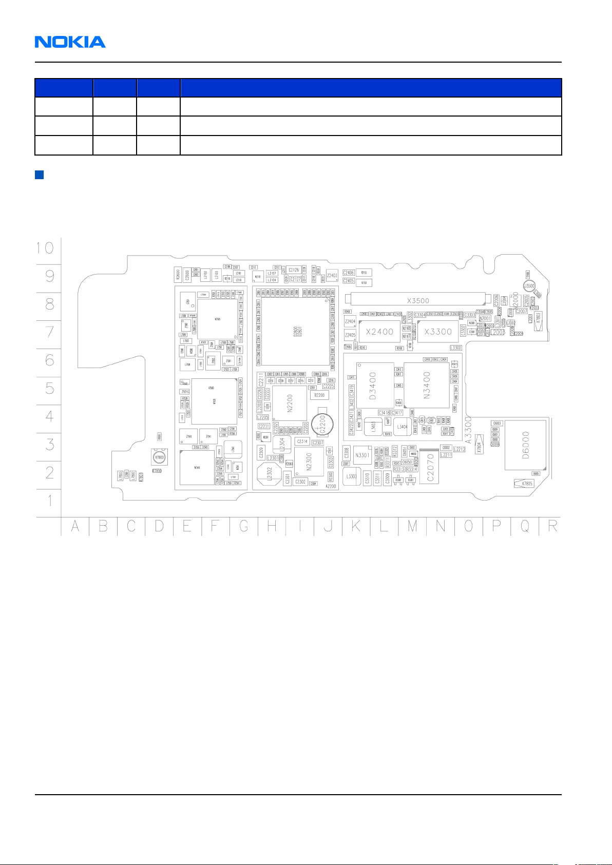
Component layouts
Note: See also large scale layouts in the Schematics section.
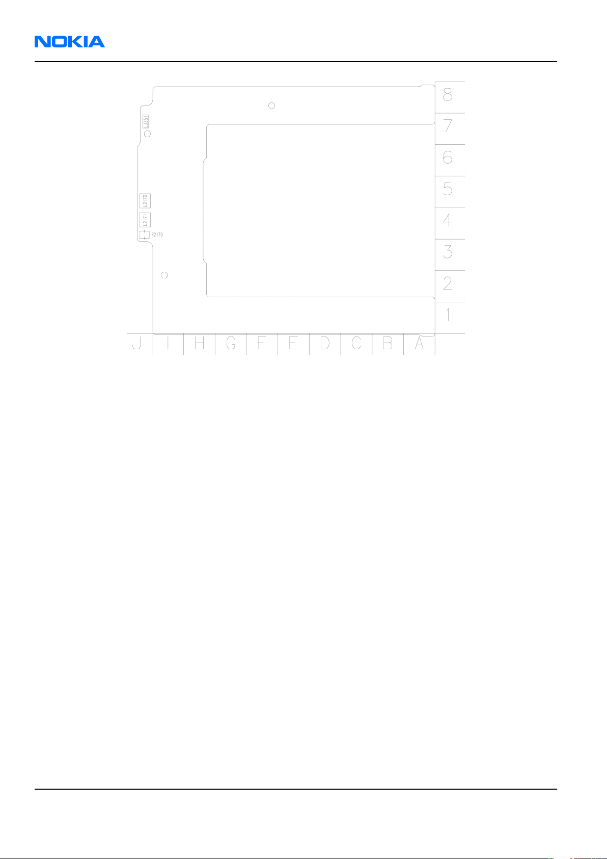
Main board (1tma)
Figure 1 Main board layout, top side (1tma_12a)
Page 2 –22 COMPANY CONFIDENTIAL Issue 1
Copyright © 2006 Nokia. All rights reserved.
Page 45
RM-140
Parts and layouts Nokia Customer Care
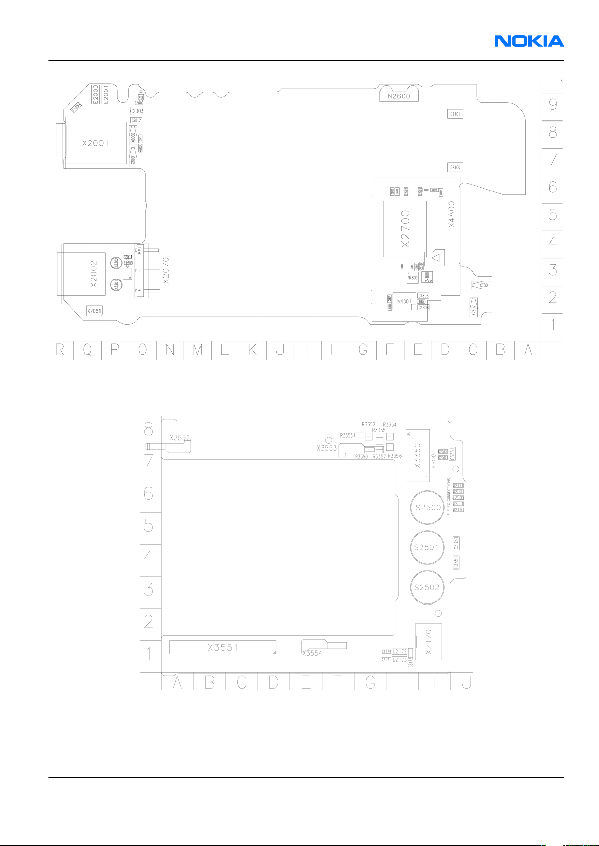
Top board (1tmb)
Figure 2 Main board layout, bottom side (1tma_12a)
Figure 3 Top board layout, top side (1tmb_04a)
Issue 1 COMPANY CONFIDENTIAL Page 2 –23
Copyright © 2006 Nokia. All rights reserved.
Page 46
RM-140
Nokia Customer Care Parts and layouts
Figure 4 Top board layout, bottom side (1tmb_04a)
Page 2 –24 COMPANY CONFIDENTIAL Issue 1
Copyright © 2006 Nokia. All rights reserved.
Page 47

Nokia Customer Care
3 — Service Software
Instructions
Issue 1 COMPANY CONFIDENTIAL Page 3 –1
Copyright © 2006 Nokia. All rights reserved.
Page 48

RM-140
Nokia Customer Care Service Software Instructions
(This page left intentionally blank.)
Page 3 –2 COMPANY CONFIDENTIAL Issue 1
Copyright © 2006 Nokia. All rights reserved.
Page 49

RM-140
Service Software Instructions Nokia Customer Care
Table of Contents
Phoenix installation steps in brief........................................................................................................................3–5
Installing Phoenix...................................................................................................................................................3–6
Updating Phoenix installation..............................................................................................................................3–8
Uninstalling Phoenix..............................................................................................................................................3–9
Repairing Phoenix installation...........................................................................................................................3–11
Phone data package overview............................................................................................................................3–11
Installing phone data package...........................................................................................................................3–12
Uninstalling phone data package.......................................................................................................................3–15
Configuring users in Phoenix..............................................................................................................................3–17
Managing connections in Phoenix......................................................................................................................3–17
Installing flash support files for FPS-8 and FPS-10...........................................................................................3–19
Updating FPS-8 and FPS-10 flash prommer software.......................................................................................3–22
Activating FPS-8....................................................................................................................................................3–23
Deactivating FPS-8................................................................................................................................................3–24
List of Figures
Figure 5 Dongle not found.....................................................................................................................................3–6
Figure 6 Disclaimer text.........................................................................................................................................3–7
Figure 7 InstallShield Wizard Complete...............................................................................................................3–8
Figure 8 Installation interrupted..........................................................................................................................3–9
Figure 9 Remove program...................................................................................................................................3–10
Figure 10 Finish uninstallation...........................................................................................................................3–10
Figure 11 Repair program...................................................................................................................................3–11
Figure 12 Data package setup information.......................................................................................................3–13
Figure 13 Data package destination folder.......................................................................................................3–14
Figure 14 InstallShield Wizard Complete...........................................................................................................3–15
Figure 15 Uninstalling phone data package......................................................................................................3–16
Figure 16 Finishing data package uninstallation..............................................................................................3–16
Figure 17 Phoenix login.......................................................................................................................................3–17
Figure 18 New user configured..........................................................................................................................3–17
Figure 19 Select mode: Manual...........................................................................................................................3–18
Figure 20 Connections list...................................................................................................................................3–19
Figure 21 Connection information.....................................................................................................................3–19
Figure 22 Product support module information (example from RM-1)..........................................................3–19
Figure 23 Flash update welcome dialog............................................................................................................3–20
Figure 24 Flash installation interrupted............................................................................................................3–20
Figure 25 Flash destination folder......................................................................................................................3–21
Figure 26 Finish flash update..............................................................................................................................3–22
Figure 27 Flash directory window......................................................................................................................3–22
Figure 28 Prommer software update finished..................................................................................................3–23
Figure 29 Prommer Maintenance window........................................................................................................3–23
Figure 30 Box activation......................................................................................................................................3–24
Figure 31 Deactivation warning.........................................................................................................................3–24
Issue 1 COMPANY CONFIDENTIAL Page 3 –3
Copyright © 2006 Nokia. All rights reserved.
Page 50

RM-140
Nokia Customer Care Service Software Instructions
(This page left intentionally blank.)
Page 3 –4 COMPANY CONFIDENTIAL Issue 1
Copyright © 2006 Nokia. All rights reserved.
Page 51

RM-140
Service Software Instructions Nokia Customer Care
Phoenix
installation steps in brief
Prerequisites
Recommended hardware requirements:
• Computer processor: Pentium 700 MHz or higher
• RAM 256 MB
• Disk space 100-300 MB
Supported operating systems:
•
Windows 2000
•
Windows XP
Service Pack 3 or higher
Service Pack 1 or higher
Context
Phoenix
is a service software for reprogramming, testing and tuning phones.
Phoenix
• Service software support for all phone models included in the package
• Flash update package files for programming devices
• All needed drivers for:
The phone model specific data package includes all changing product specific data:
• Product software binary files
• Files for type label printing
• Validation file for the faultlog repair data reporting system
• All product specific configuration files for
To use
installation contains:
• PKD-1 (DK2) dongle
• DKU-2 USB cable
Note: Separate installation packages for flash update files and drivers are also available, but it is
not necessary to use them unless there are updates between
separate update packages are used, they should be used after
installed.
Note:
Uninstallation should be made from the
Phoenix
Phoenix
, you need to:
and phone data packages should only be used as complete installation packages.
Phoenix
software components
Windows
Control Panel.
Phoenix
Phoenix
service software releases. If
and data packages have been
Steps
1. Connect a PKD-1 (DK2) dongle to the computer parallel port.
2. Install
3. Install the phone-specific data package.
4. Configure users.
5. Manage connection settings (depends on the tools you are using).
Issue 1 COMPANY CONFIDENTIAL Page 3 –5
Phoenix
If you use FPS-8: • Update FPS-8 software
.
• Activate FPS-8
Copyright © 2006 Nokia. All rights reserved.
Page 52

RM-140
Nokia Customer Care Service Software Instructions
If you use FPS-10: • Update FPS-10 software
Note: There is no need to activate FPS-10.
• Activate SX-4 smart card, if you need tuning and
testing functions.
Note: When FPS-10 is used only for
product software updates, SX-4 smart
card is not needed.
Results
Phoenix
is ready to be used with FPS-8 or FPS-10 flash prommers and other service tools.
Installing
Phoenix
Prerequisites
• Check that a dongle is attached to the parallel port of your computer.
• Download the
computer (in
• Close all other programs.
• Depending on your operating system, administrator rights may be required to install
• If uninstalling or rebooting is needed at any point, you will be prompted by the InstallShield program.
Phoenix
C:\TEMP
installation package (for example,
, for instance).
phoenix_service_sw_2004_39_x_xx.exe
Phoenix
) to your
.
Context
At some point during the installation procedure, you may get the following message:
Figure 5 Dongle not found
This may be a result of a defective or too old PKD-1 dongle.
Check the COM/parallel ports used. After correcting the problem, you can restart the installation.
For more detailed information, please refer to
Tip: Each feature in
program. Press the F1 key or the feature’s Help button to activate a Help file.
Phoenix
has its own Help function, which can be activated while running the
Phoenix
Help files.
Steps
1. To start the installation, run the application file (for example,
2. In the
Page 3 –6 COMPANY CONFIDENTIAL Issue 1
Welcome
dialogue, click Next.
Copyright © 2006 Nokia. All rights reserved.
phoenix_service_sw_2004_39_x_xx.exe
).
Page 53

RM-140
Service Software Instructions Nokia Customer Care
3. Read the disclaimer text carefully and click Yes.
Figure 6 Disclaimer text
4. Choose the destination folder.
The default folder
C:\ProgramFiles\Nokia\Phoenix
is recommended.
5. To continue, click Next.
To choose another location, click Browse (not recommended).
6. Wait for the components to be copied.
The progress of the installation is shown in the
Setup Status
window.
7. Wait for the drivers to be installed and updated.
The process may take several minutes to complete.
If the operating system does not require rebooting, the PC components are registered right away.
If the operating system requires restarting your computer, the Install Shield Wizard will notifies about it.
Select Yes... to reboot the PC immediately or No... to reboot the PC manually afterwards.
After the reboot, all components are registered.
Note:
Phoenix
does not work, if the components have not been registered.
Issue 1 COMPANY CONFIDENTIAL Page 3 –7
Copyright © 2006 Nokia. All rights reserved.
Page 54

RM-140
Nokia Customer Care Service Software Instructions
8. To end the installation, click Finish.
Figure 7 InstallShield Wizard Complete
Next actions
After the installation,
• installing phone model specific data package for
• configuring users and connections
FPS-8 and FPS-10 flash prommers can be used after updating their flash update package files.
Updating
Phoenix
Phoenix
can be used after:
Phoenix
installation
Context
• If you already have the
software when new versions are released.
• To update
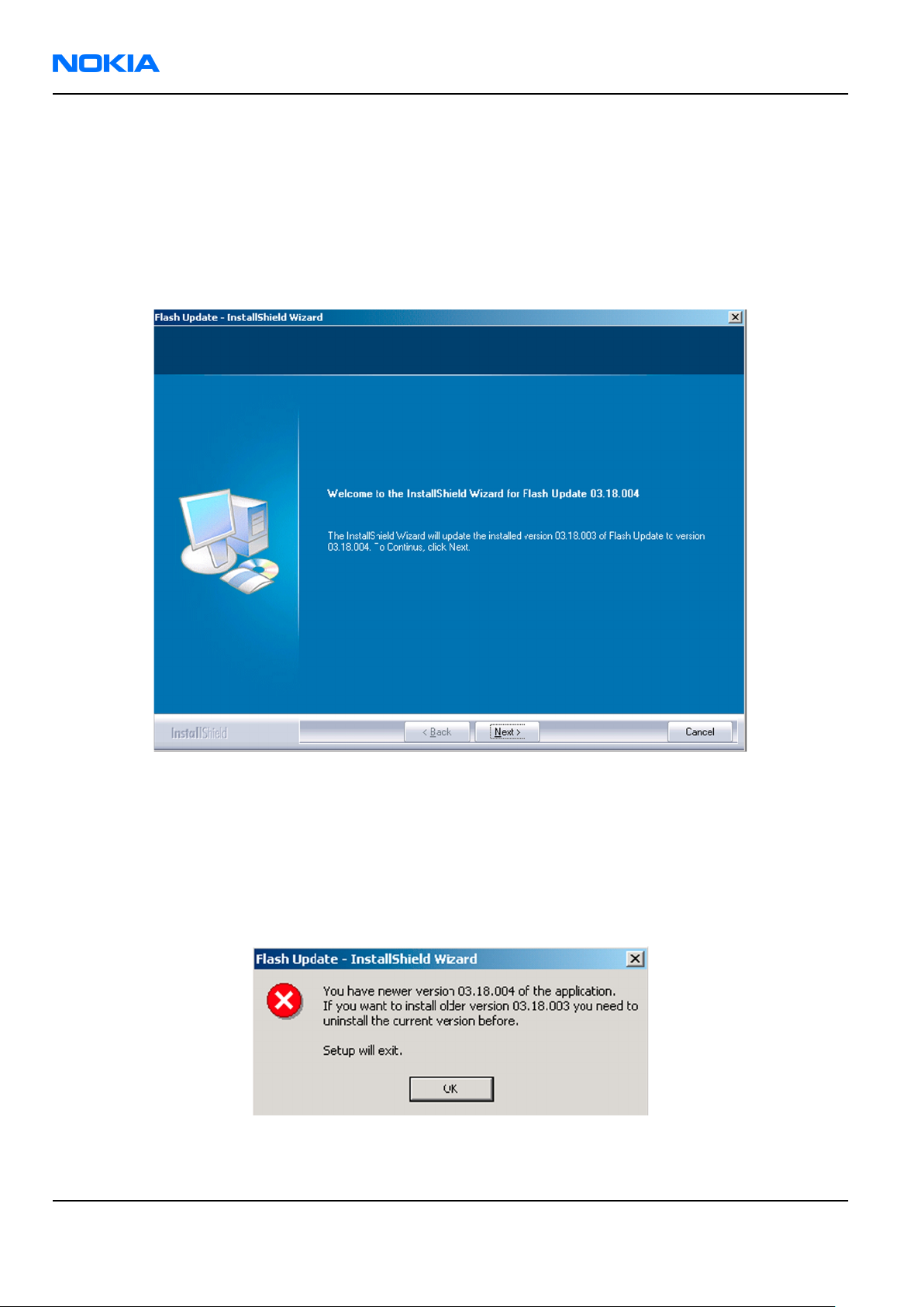
• When you are updating, for example, from version a14_2004_16_4_47 to a15_2004_24_7_55, the update
will take place automatically without uninstallation.
• Always use the latest available versions of both
can be found in the phone model specific Technical Bulletins and phone data package
(shown during installation).
• If you try to update
to a15_2004_24_7_55), you are asked if you want to uninstall the existing version. In this case you can
choose between a total uninstallation or a repair installation in a similar way when choosing to uninstall
the application from the
Phoenix
Phoenix
, you need to follow the same steps as when installing it for the first time.
Phoenix
Windows
service software installed on your computer, you need to update the
Phoenix
with the same version you already have (for example, a15_2004_24_7_55
Control Panel.
and the phone-specific data package. Instructions
readme.txt
files
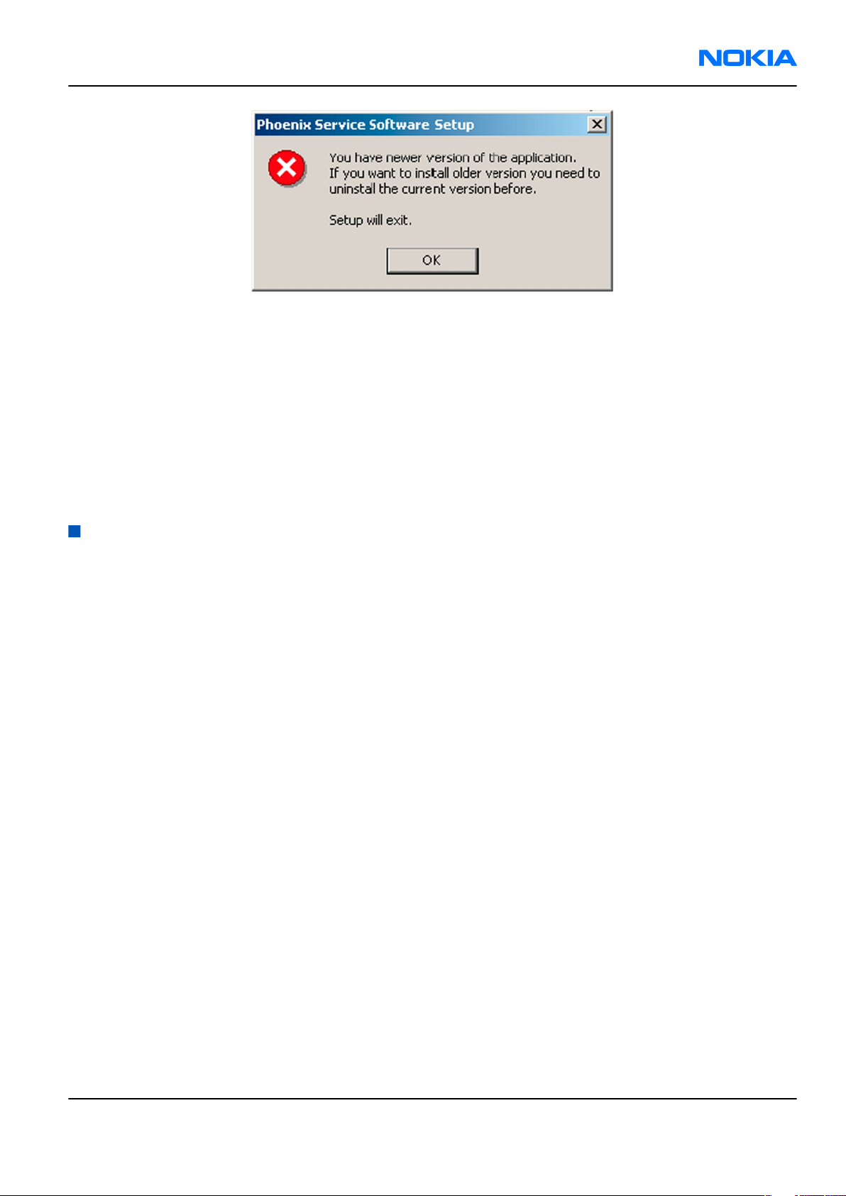
• If you try to install an older version (for example, downgrade from a15_2004_24_7_55 to
a14_2004_16_4_47), installation will be interrupted.
Page 3 –8 COMPANY CONFIDENTIAL Issue 1
Copyright © 2006 Nokia. All rights reserved.
Page 55
RM-140
Service Software Instructions Nokia Customer Care
Figure 8 Installation interrupted
• Always follow the instructions on the screen.
Steps
1. Download the installation package to your computer hard disk.
2. Close all other programs.
3. Run the application file (for example,
phoenix_service_sw_2004_39_x_xx.exe
).
Results
A new
Phoenix
version is installed and driver versions are checked and updated.
Uninstalling
Phoenix
Context
You can uninstall
Phoenix
service software manually from the
Windows
Control Panel.
Steps
1. Open the Windows Control Panel, and choose Add/Remove Programs.
Issue 1 COMPANY CONFIDENTIAL Page 3 –9
Copyright © 2006 Nokia. All rights reserved.
Page 56
RM-140
Nokia Customer Care Service Software Instructions
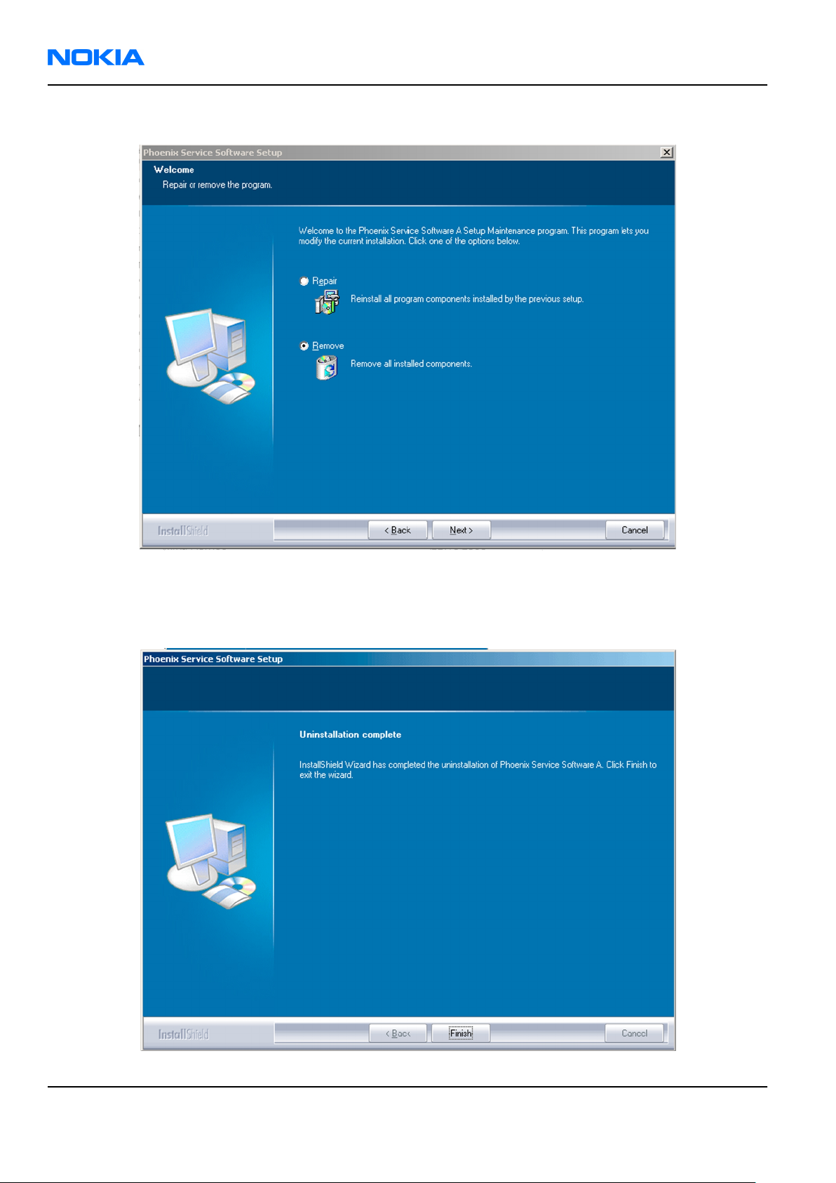
2. To uninstall
Phoenix
, choose Phoenix Service Software→Change/Remove→Remove .
Figure 9 Remove program
The progress of the uninstallation is shown.
3. If the operating system does not require rebooting, click Finish to complete.
Figure 10 Finish uninstallation
Page 3 –10 COMPANY CONFIDENTIAL Issue 1
Copyright © 2006 Nokia. All rights reserved.
Page 57

RM-140
Service Software Instructions Nokia Customer Care
If the operating system requires rebooting, InstallShield Wizard will notify you. Select Yes... to reboot the
PC immediately and No... to reboot the PC manually afterwards.
Repairing
Phoenix
installation
Context
If you experience any problems with the service software or suspect that files have been lost, use the repair
function before completely reinstalling
Note: The original installation package (for example,
must be found on your PC when you run the repair setup.
Phoenix
.
phoenix_service_sw_a15_2004_24_7_55.exe
Steps
1. Open Windows Control Panel→Add/Remove Programs .
2. Choose Phoenix Service Software→Change/Remove .
3. In the following view, select Repair.
)
Figure 11 Repair program
Phoenix
The procedure is the same as when updating
4. To complete the repair, click Finish.
reinstalls components and registers them.
Phoenix
.
Phone data package overview
Each product has its own data package (DP). The product data package contains all product-specific data files
to make the Phoenix service software and tools usable with a certain phone model.
The phone data package contains the following:
• Product software binary files
Issue 1 COMPANY CONFIDENTIAL Page 3 –11
Copyright © 2006 Nokia. All rights reserved.
Page 58

RM-140
Nokia Customer Care Service Software Instructions
• Files for type label printing
• Validation file for the fault log repair data reporting system
• All product-specific configuration files for Phoenix software components
Data files are stored in C:\Program Files\Nokia\Phoenix (default).
Installing phone data package
Prerequisites
• A phone-specific data package contains all data required for the
to be used with a certain phone model.
• Check that a dongle is attached to the parallel port of your computer.
• Install
Phoenix
service software.
Phoenix
service software and service tools
• Download the installation package (for example,
in C:\TEMP).
• Close all other programs.
(XX-XX = type designator of the product)
If you already have
released.
Note: Often
version of
available versions of both. Instructions can be found in phone-specific Technical Bulletins and
readme.txt
Phoenix
Phoenix
Phoenix
files of data packages.
installed on your computer, you will need to update it when a new version is
and the phone-specific data package come in pairs, meaning that a certain
can only be used with a certain version of a data package. Always use the latest
XX-XX_dp_EA_v_1_0.exe
Steps
1. To start the installation, run the application file (for example,
Wait for the installation files to be extracted.
) to your computer (for example,
XX-XX_dp_EA_ v_1_0.exe
),
Page 3 –12 COMPANY CONFIDENTIAL Issue 1
Copyright © 2006 Nokia. All rights reserved.
Page 59

RM-140
Service Software Instructions Nokia Customer Care
2. Click Next.
3. In the following view you can see the contents of the data package. Read the text carefully. There is
information about the
Phoenix
version required with this data package.
Figure 12 Data package setup information
4. To continue, click Next.
Issue 1 COMPANY CONFIDENTIAL Page 3 –13
Copyright © 2006 Nokia. All rights reserved.
Page 60
RM-140
Nokia Customer Care Service Software Instructions
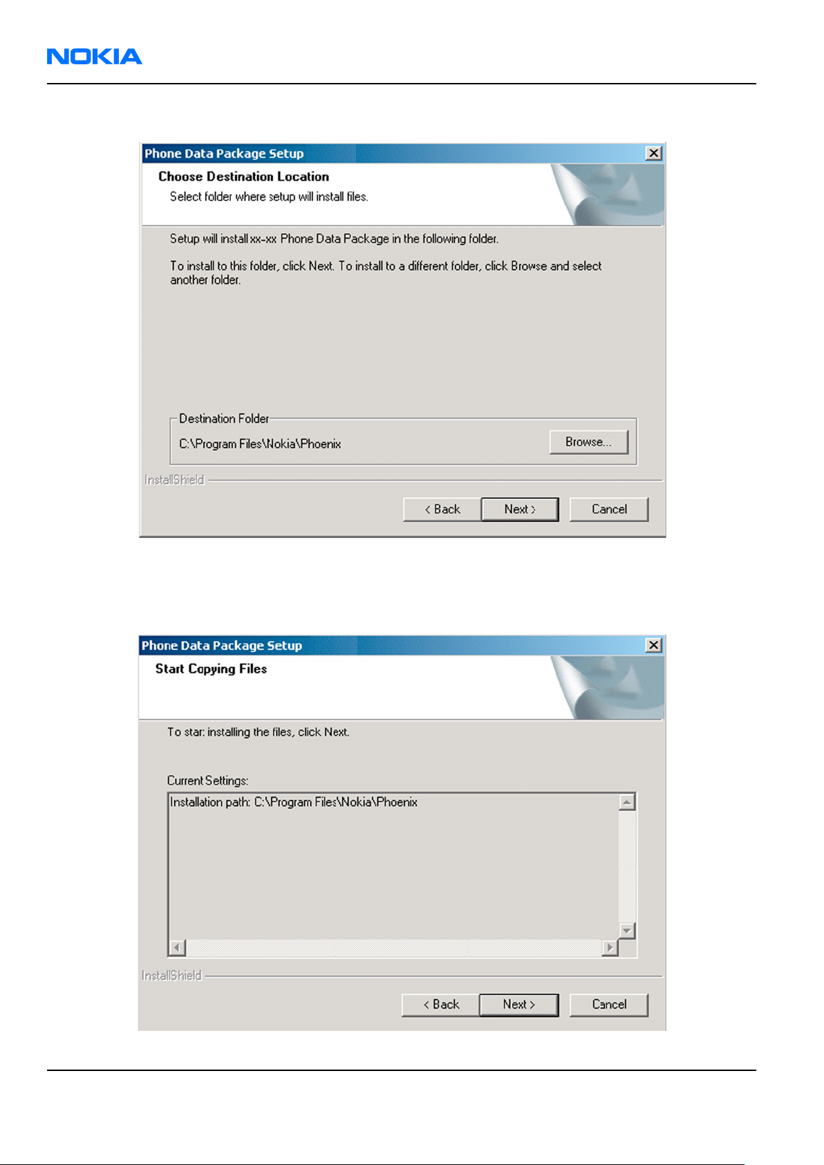
5. Choose the destination folder, and click Next to continue.
Figure 13 Data package destination folder
The InstallShield Wizard checks where
6. To start copying the files, click Next.
Phoenix
is installed, and the directory is shown.
Page 3 –14 COMPANY CONFIDENTIAL Issue 1
Copyright © 2006 Nokia. All rights reserved.
Page 61

RM-140
Service Software Instructions Nokia Customer Care
Phone model specific files are installed. Please wait.
7. To complete the installation, click Finish.
Figure 14 InstallShield Wizard Complete
Next actions
Phoenix
• Configuring users
• Managing connections
FPS-8 and FPS-10 can be used after updating their flash update package files.
can be used for flashing phones and printing type labels after:
Uninstalling phone data package
Context
There is no need to uninstall an older version of a data package, unless instructions to do so are given in
the
readme.txt
Please read all related documents carefully.
file of the data package and bulletins related to the release.
Steps
1. Locate the data package installation file (e.g.
2. To start the uninstallation procedure, double-click the data package installation file.
XX-XX_dp_EA_v_1_0.exe
) from your computer.
Issue 1 COMPANY CONFIDENTIAL Page 3 –15
Copyright © 2006 Nokia. All rights reserved.
Page 62

RM-140
Nokia Customer Care Service Software Instructions
3. To uninstall the data package, click OK or to interrupt the uninstallation, click Cancel.
Figure 15 Uninstalling phone data package
4. When the data package is uninstalled, click Finish.
Figure 16 Finishing data package uninstallation
Alternative steps
• You can also uninstall the data package manually from
Control Panel→Add/Remove Programs→xx-xx* Phone Data Package . (*= type designator of the
phone).
Page 3 –16 COMPANY CONFIDENTIAL Issue 1
Copyright © 2006 Nokia. All rights reserved.
Page 63

RM-140
Service Software Instructions Nokia Customer Care
Configuring users in
Phoenix
Steps
1. Start
2. To add a new user, or to edit existing ones, click Maintain.
3. To add a new user, click New.
4. Type in the name and initials of the user, and click OK.
5. Select the desired user from the
Phoenix
If the user ID is already configured, select s/he from the
The user is added to the user name list.
service software, and log in.
Figure 17 Phoenix login
User name
drop-down list, and click OK.
User name
drop-down list, and click OK.
Figure 18 New user configured
Managing connections in
Phoenix
Context
With the Manage Connections feature you can edit and delete existing connections or create new ones.
Note: After choosing the desired connection, and connecting the phone to a PC for the first time,
allow the PC to install the USB device drivers first. Please note that this may take some time to
complete.
If there are problems after the driver installation, check that the USB connection is active from
the Windows Control Panel. If the problem persists, contact the local PC support.
Steps
1. Start
2. Choose File→Manage Connections... .
Issue 1 COMPANY CONFIDENTIAL Page 3 –17
Phoenix
, and log in.
Copyright © 2006 Nokia. All rights reserved.
Page 64

RM-140
Nokia Customer Care Service Software Instructions
3. To add a new connection, click Add.
4. Select Manual mode, and click Next to continue.
If you want to create the connection using the Connection Wizard, connect the tools and a phone to your
PC. The wizard will automatically try to configure the correct connection.
Figure 19 Select mode: Manual
i For an FPS-10 flash prommer with a USB Connection, choose the following connection settings:
• Media: FPS-10 USB
• DEVICE_INDEX: 0
• SERIAL_NUM: See Serial No from the label attached to the bottom of FPS-10
• ACTIVE_MEDIA: USB
ii For an FPS-10 flash prommer with a LAN connection, choose the following connection settings:
• Media: FPS-10 TCP/IP
• NET_SERV_NAME: Click Scan.... Choose your own FPS-10 device based on the correct MAC address.
See Serial No from the label attached to the bottom of your FPS-10.
• PORT_NUM: Use the default value, and click Next.
• PROTOCOL_FAMILY: Use the default value, and click Next.
• SOCKET TYPE: Use the default value, and click Next.
• TX_BUFFER_SIZE: Use the default value, and click Next.
• RX_BUFFER_SIZE: Use the default value, and click Next.
iii For an FPS-8 flash prommer, choose the following connection settings:
• Media: FPS-8
• PORT_NUM: COM Port where FPS-8 is connected
• COMBOX_DEF_MEDIA: FBUS
Page 3 –18 COMPANY CONFIDENTIAL Issue 1
Copyright © 2006 Nokia. All rights reserved.
Page 65

RM-140
Service Software Instructions Nokia Customer Care
iv For a plain USB connection, choose the following connection settings:
Note: First connect the DKU-2 USB cable between the PC USB port and phone.
• Media: USB
5. To complete the configuration, click Finish.
6. Click the connection you want to activate. Use the up/down arrows located on the right hand side to move
it on top of the list, then click Apply.
Figure 20 Connections list
The connection is activated, and it can be used after closing the
The connection information is shown at the right hand bottom corner of the screen.
Figure 21 Connection information
7. To use the connection, connect the phone to your PC with correct service tools. Make sure the phone is
switched on, and then choose File→Scan Product .
Manage Connection
window.
Results
The product support module information appears in the status bar:
Figure 22 Product support module information (example from RM-1)
Installing flash support files for FPS-8 and FPS-10
Prerequisites
• Install
• Install phone model specific data package for
• If you want to update the flash support files, they are delivered in the same installation package with
Phoenix
Phoenix
or newer
service software.
Phoenix
packages beginning from December 2004.
Phoenix
.
In case you want to update the MCU files, install the latest data package (see Technical Bulletins for
information on the latest one).
Normally, it is enough to install
always includes the latest flash update package files for FPS-8 and FPS-10.
• A separate installation package for flash support files is available. The files can be updated according to
these instructions, if updates appear between
Issue 1 COMPANY CONFIDENTIAL Page 3 –19
Phoenix
Copyright © 2006 Nokia. All rights reserved.
and the phone-specific data package because the installation
Phoenix
data package releases.
Page 66
RM-140
Nokia Customer Care Service Software Instructions
Context
If you are not using a separate installation package, you can skip this section and continue with "Updating
FPS-8 and FPS-10 flash prommer software" (page 3–22) after installing a new phone data package.
Steps
1. To begin the installation, double-click the flash update file (for example,
flash_update_03_183_0014.exe
).
Figure 23 Flash update welcome dialog
If the same version of the flash update package already exists, and you want to reinstall it, the previous
package is first uninstalled.
Restart installation again after the uninstallation.
2. If you try to downgrade the existing version to older ones, the setup will be aborted. If there is a need to
downgrade the version, uninstall newer files manually from the Windows Control Panel, and then rerun
the installation.
Figure 24 Flash installation interrupted
If an older version exists on your PC and it needs to be updated, click Next to continue installation.
Page 3 –20 COMPANY CONFIDENTIAL Issue 1
Copyright © 2006 Nokia. All rights reserved.
Page 67

RM-140
Service Software Instructions Nokia Customer Care
3. It is recommended to install the files to the default destination folder
To continue, click Next.
C:\Program Files\Nokia\Phoenix
.
Figure 25 Flash destination folder
When installing the flash update files for the first time, you may choose another location by selecting
Browse (not recommended).
Issue 1 COMPANY CONFIDENTIAL Page 3 –21
Copyright © 2006 Nokia. All rights reserved.
Page 68

RM-140
Nokia Customer Care Service Software Instructions
4. To complete the installation procedure, click Finish .
Figure 26 Finish flash update
Next actions
FPS-8 and FPS-10 flash prommers must be updated using
Updating FPS-8 and FPS-10 flash prommer software
Phoenix
.
Steps
1. Start
2. Choose the correct connection for your flash prommer: File→Manage Connections...
3. Choose Flashing→Prommer maintenance .
4. To update the FPS-8/FPS-10 software, click Update, and select the appropriate file
Phoenix
or
fpsxupd.ini
service software, and log in.
(for FPS-10) from
C:\Program Files\Nokia\Phoenix\Flash
fps8upd.ini
.
(for FPS-8)
Figure 27 Flash directory window
Page 3 –22 COMPANY CONFIDENTIAL Issue 1
Copyright © 2006 Nokia. All rights reserved.
Page 69

RM-140
Service Software Instructions Nokia Customer Care
Tip: All files can be loaded separately to the prommer used. To do this, click the right mouse button
in the
Flash Box Files
pane and select the file type(s) to be loaded.
5. Click OK.
Figure 28 Prommer software update finished
6. To close the
Prommer Maintenance
window, click Close.
Figure 29
Prommer Maintenance
window
Activating FPS-8
Context
Before FPS-8 can be successfully used for phone programming, it must first be activated.
First fill in the
When activation file is received (for example,
\BoxActivation
Issue 1 COMPANY CONFIDENTIAL Page 3 –23
FPS-8 activation request
sheet in the FPS-8 sales package, and follow the instructions given.
00000.in
), copy it to the
C:\ProgramFiles\Nokia\Phoenix
directory on your computer (this directory is created when
Copyright © 2006 Nokia. All rights reserved.
Phoenix
is installed).
Page 70
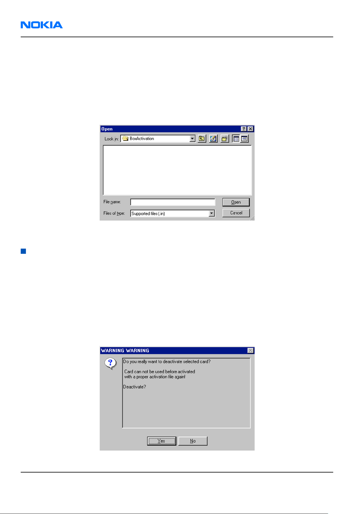
RM-140
Nokia Customer Care Service Software Instructions
Steps
1. Start
2. Choose Flashing→Prommer Maintenance .
Phoenix
service software.
3. In the
4. To find the activation file, click Browse.
5. To activate the prommer, select the activation file and click Open.
6. To complete the activation, restart FPS-8.
Prommer Maintenance
window, click Activate.
Figure 30 Box activation
Deactivating FPS-8
Context
If there is, for example, a need to send the FPS-8 box for repair, it must be deactivated first.
Steps
1. Start
2. Choose Flashing→Prommer Maintenance .
3. In the
4. To confirm the deactivation, click Yes.
Phoenix
service software.
Prommer Maintenance
window, click Deactivate.
Figure 31 Deactivation warning
Page 3 –24 COMPANY CONFIDENTIAL Issue 1
Copyright © 2006 Nokia. All rights reserved.
Page 71

RM-140
Service Software Instructions Nokia Customer Care
The box is deactivated.
5. To complete the deactivation, restart FPS-8.
Issue 1 COMPANY CONFIDENTIAL Page 3 –25
Copyright © 2006 Nokia. All rights reserved.
Page 72

RM-140
Nokia Customer Care Service Software Instructions
(This page left intentionally blank.)
Page 3 –26 COMPANY CONFIDENTIAL Issue 1
Copyright © 2006 Nokia. All rights reserved.
Page 73

Nokia Customer Care
4 — Service Tools and Service
Concepts
Issue 1 COMPANY CONFIDENTIAL Page 4 –1
Copyright © 2006 Nokia. All rights reserved.
Page 74

RM-140
Nokia Customer Care Service Tools and Service Concepts
(This page left intentionally blank.)
Page 4 –2 COMPANY CONFIDENTIAL Issue 1
Copyright © 2006 Nokia. All rights reserved.
Page 75

RM-140
Service Tools and Service Concepts Nokia Customer Care
Table of Contents
Service tools............................................................................................................................................................4–5
Product specific tools........................................................................................................................................4–5
FS-24..............................................................................................................................................................4–5
MJ-96..............................................................................................................................................................4–6
RJ-112............................................................................................................................................................4–6
SA-101...........................................................................................................................................................4–7
SS-111............................................................................................................................................................4–7
SS-81..............................................................................................................................................................4–7
General tools......................................................................................................................................................4–7
CU-4................................................................................................................................................................4–8
FLS-5..............................................................................................................................................................4–9
FPS-10............................................................................................................................................................4–9
JBT-9..............................................................................................................................................................4–9
JXS-1.............................................................................................................................................................4–10
PK-1..............................................................................................................................................................4–10
PKD-1...........................................................................................................................................................4–10
RJ-104..........................................................................................................................................................4–10
RJ-114..........................................................................................................................................................4–10
RJ-57............................................................................................................................................................4–11
RJ-93............................................................................................................................................................4–11
SPS-1............................................................................................................................................................4–11
SRT-6............................................................................................................................................................4–11
SS-46............................................................................................................................................................4–12
SS-62............................................................................................................................................................4–12
ST-37............................................................................................................................................................4–12
ST-40............................................................................................................................................................4–12
ST-41............................................................................................................................................................4–12
ST-44............................................................................................................................................................4–13
SX-4..............................................................................................................................................................4–13
Cables...............................................................................................................................................................4–13
CA-31D.........................................................................................................................................................4–13
CA-35S..........................................................................................................................................................4–13
DKE-2...........................................................................................................................................................4–14
PCS-1............................................................................................................................................................4–14
XCS-4............................................................................................................................................................4–14
XRF-1............................................................................................................................................................4–14
Service concepts...................................................................................................................................................4–15
POS (Point of Sale) flash concept...................................................................................................................4–15
Flash concept with FPS-10..............................................................................................................................4–16
CU-4 flash concept with FPS-10......................................................................................................................4–17
Module jig service concept.............................................................................................................................4–18
RF testing concept with RF coupler...............................................................................................................4–19
Service concept for RF testing and RF/BB tuning.........................................................................................4–20
List of Figures
Figure 32 Mode switch...........................................................................................................................................4–6
Figure 33 POS flash concept................................................................................................................................4–15
Figure 34 Basic flash concept with FPS-10.........................................................................................................4–16
Figure 35 CU-4 flash concept with FPS-10..........................................................................................................4–17
Issue 1 COMPANY CONFIDENTIAL Page 4 –3
Copyright © 2006 Nokia. All rights reserved.
Page 76

RM-140
Nokia Customer Care Service Tools and Service Concepts
Figure 36 Module jig service concept.................................................................................................................4–18
Figure 37 RF testing concept with RF coupler...................................................................................................4–19
Figure 38 Service concept for RF testing and RF/BB tuning.............................................................................4–20
Page 4 –4 COMPANY CONFIDENTIAL Issue 1
Copyright © 2006 Nokia. All rights reserved.
Page 77

RM-140
Service Tools and Service Concepts Nokia Customer Care
Service tools
Product specific tools
The table below gives a short overview of service tools that can be used for testing, error analysis and repair
of product RM-140, refer to various concepts.
FS-24 Flash adapter
• FS-24 is equipped with a clip interlock system
• provides standardised interface towards Control Unit
• provides RF connection using coupler
• multiplexing between USB and FBUS media, controlled by VUSB
Issue 1 COMPANY CONFIDENTIAL Page 4 –5
Copyright © 2006 Nokia. All rights reserved.
Page 78

RM-140
Nokia Customer Care Service Tools and Service Concepts
MJ-96 Module jig MJ-96 is meant for component level troubleshooting.
The jig includes an RF interface for GSM, WCDMA and Bluetooth. In
addition, it has the following features:
• Provides mechanical interface with the engine module
• Provides galvanic connection to all needed test pads in module
• Multiplexing between USB and FBUS media, controlled by Vusb
• MMC interface
• Duplicated SIM connector
• Connector for control unit
• Access for AV- and USB connectors
Note: Be careful when closing the jig, not to harm the display
with the screws on the jig!
Figure 32 Mode switch
RJ-112 Soldering jig RJ-112 is a soldering jig used for soldering and as a rework jig for the
engine module.
Page 4 –6 COMPANY CONFIDENTIAL Issue 1
Copyright © 2006 Nokia. All rights reserved.
Page 79

RM-140
Service Tools and Service Concepts Nokia Customer Care
SA-101 RF coupler SA-101 is an RF coupler for WCDMA and GSM RF testing. It is used
together with the product-specific flash adapter.
The following table shows attenuations from the antenna pads of the
mobile terminal to the SMA connectors of SA-101:
•
GSM900 TX 2,7 dB +/- 0,5 dB
GSM900 RX 2,6 dB +/- 0,7 dB
GSM1800 TX 8,2 dB +/- 2,0 dB
GSM1800 RX 5,3 dB +/- 0,4 dB
GSM1900 TX 5,1 dB +/- 0,1dB
GSM1900 RX 5,2 dB +/- 0,6 dB
WCDMA2100 TX 10,0 dB +/- 0,9dB
WCDMA2100 RX 6,8 dB +/- 0,4 dB
SS-111 Coax tool
SS-81 Camera removal tool
Frequency Att. (dB)
Camera removal tool for main camera.
General tools
The table below gives a short overview of service tools that can be used for testing, error analysis and repair
of product RM-140, refer to various concepts.
Issue 1 COMPANY CONFIDENTIAL Page 4 –7
Copyright © 2006 Nokia. All rights reserved.
Page 80

RM-140
Nokia Customer Care Service Tools and Service Concepts
CU-4 Control unit CU-4 is a general service tool used with a module jig and/or a flash
adapter. It requires an external 12 V power supply.
The unit has the following features:
• software controlled via USB
• EM calibration function
• Forwards FBUS/Flashbus traffic to/from terminal
• Forwards USB traffic to/from terminal
• software controlled BSI values
• regulated VBATT voltage
• 2 x USB2.0 connector (Hub)
• FBUS and USB connections supported
When using CU-4, note the special order of connecting cables and
other service equipment:
Instructions
1 Connect a service tool (jig, flash adapter) to CU-4.
2 Connect CU-4 to your PC with a USB cable.
3 Connect supply voltage (12 V)
4 Connect an FBUS cable (if necessary).
5 Start Phoenix service software.
Note: Phoenix enables CU-4 regulators via USB when it is
started.
Reconnecting the power supply requires a Phoenix restart.
Page 4 –8 COMPANY CONFIDENTIAL Issue 1
Copyright © 2006 Nokia. All rights reserved.
Page 81

RM-140
Service Tools and Service Concepts Nokia Customer Care
FLS-5 Flash device FLS-5 is a dongle and flash device incorporated into one package,
developed specifically for POS use.
FPS-10 Flash prommer FPS-10 interfaces with:
• PC
• Control unit
• Flash adapter
• Smart card
FPS-10 flash prommer features:
• Flash functionality for BB5 and DCT-4 terminals
• Smart Card reader for SX-2 or SX-4
• USB traffic forwarding
• USB to FBUS/Flashbus conversion
• LAN to FBUS/Flashbus and USB conversion
• Vusb output switchable by PC command
FPS-10 sales package includes:
• FPS-10 prommer
• Power Supply with 5 country specific cords
• USB cable
JBT-9 Bluetooth test and
interface box (sales
package)
The JBT-9 test box is a generic service device used to perform
Bluetooth bit error rate (BER) testing, and establishing cordless FBUS
connection via Bluetooth. An ACP-8x charger is needed for BER testing
and an AXS-4 cable in case of cordless interface usage testing .
Sales package includes:
• JBT-9 test box
• Installation and warranty information
Issue 1 COMPANY CONFIDENTIAL Page 4 –9
Copyright © 2006 Nokia. All rights reserved.
Page 82

RM-140
Nokia Customer Care Service Tools and Service Concepts
JXS-1 RF shield box Because the WCDMA network disturbs the RX side testing of the WCDMA
phone and the Tx signal of the WCDMA phone can severely disturb the
WCDMA network, a shield box is needed in all testing, tuning and fault
finding which requires WCDMA RF signal.
The shield box is not an active device, it contains only passive filtering
components for RF attenuation.
PK-1 Software protection
key
PK-1 is a hardware protection key with a USB interface. It has the same
functionality as the PKD-1 series dongle.
PK-1 is meant for use with a PC that does not have a series interface.
To use this USB dongle for security service functions please register
the dongle in the same way as the PKD-1 series dongle.
PKD-1 SW security device
SW security device is a piece of hardware enabling the use of the
service software when connected to the parallel (LPT) port of the PC.
Without the device, it is not possible to use the service software.
Printer or any such device can be connected to the PC through the
device if needed.
RJ-104 Rework jig RJ-104 is a rework jig used when servicing the BTHFM module. It is
used together with rework stencil ST-37.
RJ-114 Rework jig RJ-114 is a rework jig used with ST-41.
Page 4 –10 COMPANY CONFIDENTIAL Issue 1
Copyright © 2006 Nokia. All rights reserved.
Page 83

RM-140
Service Tools and Service Concepts Nokia Customer Care
RJ-57 Rework jig RJ-57 is a rework jig used with ST-22.
RJ-93 Rework jig RJ-93 is used as a rework jig for the engine module.
This stencil takes the front end module (FEM) or power amplifier (PA)
module for spreading the soldering paste to the component. Must be
used together with the ST-40 stencil.
SPS-1 Soldering Paste
Spreader
SRT-6 Opening tool SRT-6 is used to open phone covers and B-to-B connectors.
Issue 1 COMPANY CONFIDENTIAL Page 4 –11
Copyright © 2006 Nokia. All rights reserved.
Page 84

RM-140
Nokia Customer Care Service Tools and Service Concepts
SS-46 Interface adapter SS-46 acts as an interface adapter between the flash adapter and
FPS-10.
SS-62 Generic flash adapter
base for BB5
• generic base for flash adapters and couplers
• SS-62 equipped with a clip interlock system
• provides standardised interface towards Control Unit
• provides RF connection using galvanic connector or coupler
• multiplexing between USB and FBUS media, controlled by VUSB
ST-37 BTHFM rework stencil ST-37 stencil is used with RJ-104 BTHFM rework jig.
ST-40 rework stencil ST-40 is a rework stencil and used with RJ-93.
ST-41 Rework stencil ST-41 is a rework stencil used with rework jig RJ-114.
Page 4 –12 COMPANY CONFIDENTIAL Issue 1
Copyright © 2006 Nokia. All rights reserved.
Page 85

RM-140
Service Tools and Service Concepts Nokia Customer Care
ST-44 Rework stencil ST-44 is a rework stencil used with rework jig RJ-57.
SX-4 Smart card SX-4 is a BB5 security device used to protect critical features in tuning
and testing.
SX-4 is also needed together with FPS-10 when DCT-4 phones are
flashed.
Cables
The table below gives a short overview of service tools that can be used for testing, error analysis and repair
of product RM-140, refer to various concepts.
CA-31D USB cable The CA-31D USB cable is used to connect FPS-10 or FPS-11 to a PC. It is
included in the FPS-10 and FPS-11 sales packages.
CA-35S Power cable CA-35S is a power cable for connecting, for example, the FPS-10 flash
prommer to the Point-Of-Sales (POS) flash adapter.
Issue 1 COMPANY CONFIDENTIAL Page 4 –13
Copyright © 2006 Nokia. All rights reserved.
Page 86

RM-140
Nokia Customer Care Service Tools and Service Concepts
DKE-2 Mini-USB cable USB to mini-USB connector cable.
PCS-1 Power cable The PCS-1 power cable (DC) is used with a docking station, a module
jig or a control unit to supply a controlled operating voltage.
XCS-4 Modular cable XCS-4 is a shielded (one specially shielded conductor) modular cable
for flashing and service purposes.
XRF-1 RF cable The RF cable is used to connect, for example, a module repair jig to
the RF measurement equipment.
SMA to N-Connector ca. 610mm.
Attenuation for:
• GSM850/900: 0.3+-0.1 dB
• GSM1800/1900: 0.5+-0.1 dB
• WLAN: 0.6+-0.1dB
Page 4 –14 COMPANY CONFIDENTIAL Issue 1
Copyright © 2006 Nokia. All rights reserved.
Page 87

RM-140
Service Tools and Service Concepts Nokia Customer Care
Service concepts
POS (Point of Sale) flash concept
Figure 33 POS flash concept
Type Description
Product specific tools
BP-5M Battery
Other tools
FLS-5 POS flash dongle
PC with Phoenix service software
Cables
DKE-2 USB connectivity cable
Issue 1 COMPANY CONFIDENTIAL Page 4 –15
Copyright © 2006 Nokia. All rights reserved.
Page 88

RM-140
Nokia Customer Care Service Tools and Service Concepts
Flash concept with FPS-10
Figure 34 Basic flash concept with FPS-10
Type Description
Product specific tools
FS-24 Flash adapter
Other tools
FPS-10 Flash prommer box
PKD-1/PK-1 SW security device
SS-46 Interface adapter
PC with Phoenix service software
Cables
XCS-4 Modular cable
CA-35S Power cable
USB cable
Page 4 –16 COMPANY CONFIDENTIAL Issue 1
Copyright © 2006 Nokia. All rights reserved.
Page 89
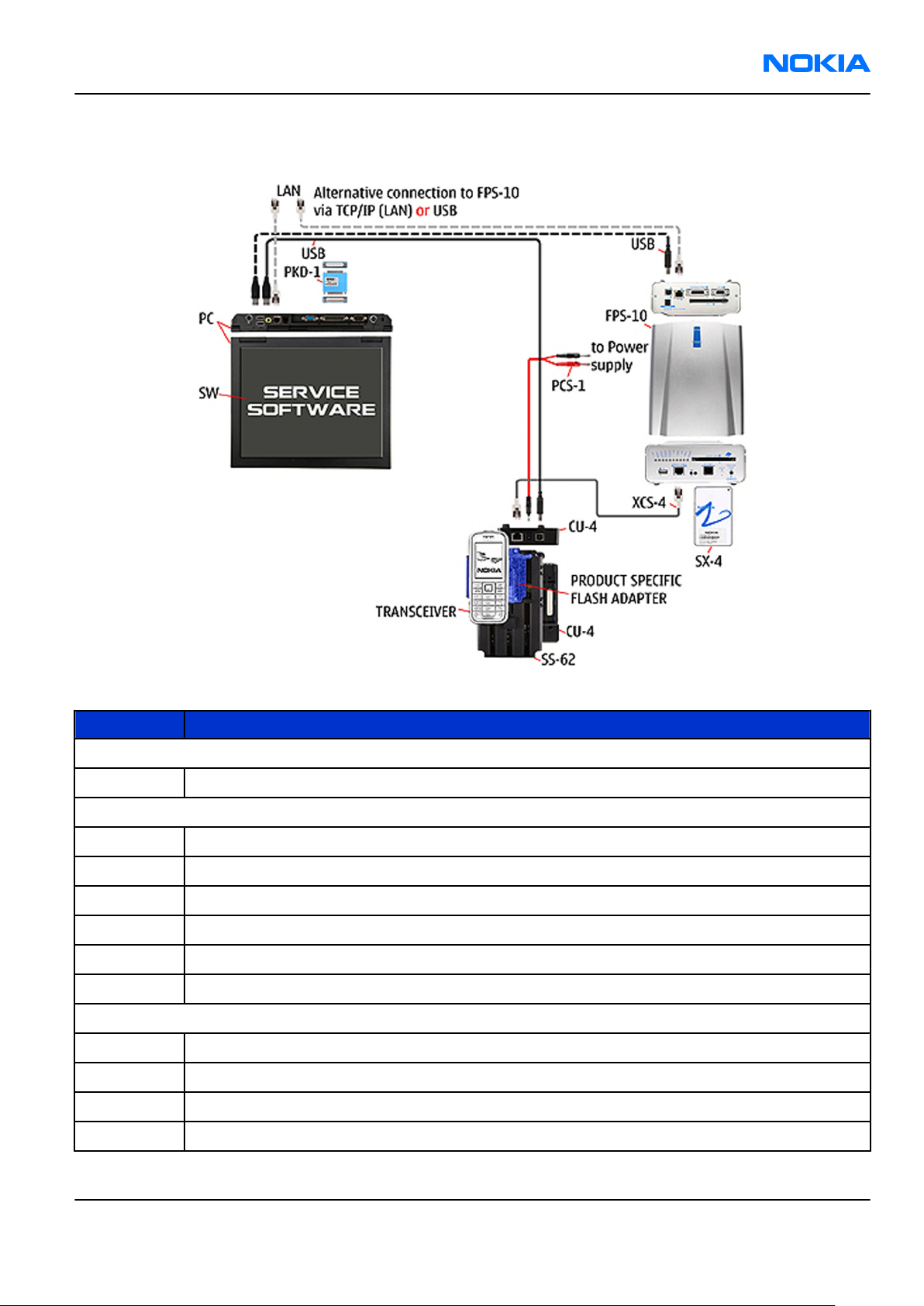
RM-140
Service Tools and Service Concepts Nokia Customer Care
CU-4 flash concept with FPS-10
Figure 35 CU-4 flash concept with FPS-10
Type Description
Product specific tools
FS-24 Flash adapter
Other tools
CU-4 Control unit
FPS-10 Flash prommer box
PKD-1/PK-1 SW security device
SS-62 Flash adapter base
SX-4 Smart card
PC with Phoenix service software
Cables
PCS-1 Power cable
XCS-4 Modular cable
Standard USB cable
USB cable
Issue 1 COMPANY CONFIDENTIAL Page 4 –17
Copyright © 2006 Nokia. All rights reserved.
Page 90

RM-140
Nokia Customer Care Service Tools and Service Concepts
Module jig service concept
Figure 36 Module jig service concept
Type Description
Phone specific tools
MJ-96 Module jig
Other tools
CU-4 Control unit
FPS-10 Flash prommer box
PKD-1/PK-1 SW security device
SX-4 Smart card
PC with Phoenix service software
Measurement equipment
Cables
PCS-1 DC power cable
XCS-4 Modular cable
XRS-6 RF cable
USB cable
Page 4 –18 COMPANY CONFIDENTIAL Issue 1
Copyright © 2006 Nokia. All rights reserved.
Page 91

RM-140
Service Tools and Service Concepts Nokia Customer Care
Type Description
GPIB control cable
RF testing concept with RF coupler
Figure 37 RF testing concept with RF coupler
Type Description
Product specific tools
FS-24 Flash adapter
SA-101 RF coupler
Other tools
CU-4 Control unit
SX-4 Smart card
FPS-10 Flash prommer box
PKD-1/PK-1 SW security device
SS-62 Flash adapter base
Measurement equipment
PC with Phoenix service software
Cables
PCS-1 Power cable
Issue 1 COMPANY CONFIDENTIAL Page 4 –19
Copyright © 2006 Nokia. All rights reserved.
Page 92
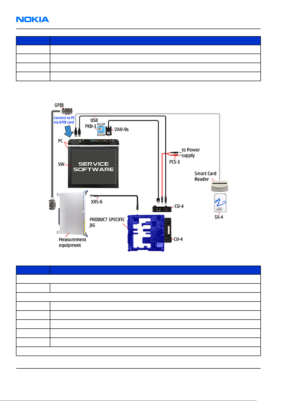
RM-140
Nokia Customer Care Service Tools and Service Concepts
Type Description
XCS-4 Modular cable
XRS-6 RF cable
GPIB control cable
USB cable
Service concept for RF testing and RF/BB tuning
Figure 38 Service concept for RF testing and RF/BB tuning
Type Description
Product specific tools
MJ-96 Module jig
Other tools
CU-4 Control unit
SX-4 Smart card
Measurement equipment
Smart card reader
PC with Phoenix service software
Cables
Page 4 –20 COMPANY CONFIDENTIAL Issue 1
Copyright © 2006 Nokia. All rights reserved.
Page 93

RM-140
Service Tools and Service Concepts Nokia Customer Care
Type Description
DAU-9s MBUS cable
PCS-1 DC power cable
PKD-1/PK-1 SW security device
XRS-6 RF cable
GPIB control cable
USB cable
Issue 1 COMPANY CONFIDENTIAL Page 4 –21
Copyright © 2006 Nokia. All rights reserved.
Page 94

RM-140
Nokia Customer Care Service Tools and Service Concepts
(This page left intentionally blank.)
Page 4 –22 COMPANY CONFIDENTIAL Issue 1
Copyright © 2006 Nokia. All rights reserved.
Page 95

Nokia Customer Care
5 — Disassembly and
reassembly instructions
Issue 1 COMPANY CONFIDENTIAL Page 5 –1
Copyright © 2006 Nokia. All rights reserved.
Page 96

RM-140
Nokia Customer Care Disassembly and reassembly instructions
(This page left intentionally blank.)
Page 5 –2 COMPANY CONFIDENTIAL Issue 1
Copyright © 2006 Nokia. All rights reserved.
Page 97

RM-140
Disassembly and reassembly instructions Nokia Customer Care
Table of Contents
Upper block disassembly instruction...................................................................................................................5–5
Upper block reassembly instruction...................................................................................................................5–13
Lower block disassembly instruction.................................................................................................................5–22
Lower block reassembly instruction..................................................................................................................5–32
Hinge disassembly instruction............................................................................................................................5–41
Issue 1 COMPANY CONFIDENTIAL Page 5 –3
Copyright © 2006 Nokia. All rights reserved.
Page 98

RM-140
Nokia Customer Care Disassembly and reassembly instructions
(This page left intentionally blank.)
Page 5 –4 COMPANY CONFIDENTIAL Issue 1
Copyright © 2006 Nokia. All rights reserved.
Page 99

RM-140
Disassembly and reassembly instructions Nokia Customer Care
Upper block disassembly instruction
Steps
1. Needed tools: a Torx driver, a torque driver with a bit holder, a Torx plus size 4 bit, the SS-93, metal
tweezers, the SS-111 connector opening tool and the SRT-6.
2. Always cover all sensitive surfaces with a protective film.
Issue 1 COMPANY CONFIDENTIAL Page 5 –5
Copyright © 2006 Nokia. All rights reserved.
Page 100

RM-140
Nokia Customer Care Disassembly and reassembly instructions
3. Open and remove the BATTERY COVER. If a battery is inserted, take it out.
4. Protect the window with the film.
5. To separate the covers of the upper block begin with the SRT-6 on the shown side.
Page 5 –6 COMPANY CONFIDENTIAL Issue 1
Copyright © 2006 Nokia. All rights reserved.
 Loading...