

Page 1

Nokia Customer Care
Service Manual
RM-111 (Nokia 7380)
Mobile Terminal
Part No: 9245926 (Issue 1)
COMPANY CONFIDENTIAL
Copyright © 2005 Nokia. All rights reserved.
Page 2
RM-111
Nokia Customer Care Amendment Record Sheet
Amendment Record Sheet
Amendment No Date Inserted By Comments
Original issue 11/2005 J Bryman
Page ii COMPANY CONFIDENTIAL Issue 1
Copyright © 2005 Nokia. All rights reserved.
Page 3

RM-111
Copyright Nokia Customer Care
Copyright
Copyright © 2005 Nokia. All rights reserved.
Reproduction, transfer, distribution or storage of part or all of the contents in this document in any form
without the prior written permission of Nokia is prohibited.
Nokia, Nokia Connecting People, and Nokia X and Y are trademarks or registered trademarks of Nokia
Corporation. Other product and company names mentioned herein may be trademarks or tradenames of
their respective owners.
Nokia operates a policy of continuous development. Nokia reserves the right to make changes and
improvements to any of the products described in this document without prior notice.
Under no circumstances shall Nokia be responsible for any loss of data or income or any special, incidental,
consequential or indirect damages howsoever caused.
The contents of this document are provided “as is„. Except as required by applicable law, no warranties of
any kind, either express or implied, including, but not limited to, the implied warranties of merchantability
and fitness for a particular purpose, are made in relation to the accuracy, reliability or contents of this
document. Nokia reserves the right to revise this document or withdraw it at any time without prior notice.
The availability of particular products may vary by region.
IMPORTANT
This document is intended for use by qualified service personnel only.
Issue 1 COMPANY CONFIDENTIAL Page iii
Copyright © 2005 Nokia. All rights reserved.
Page 4

RM-111
Nokia Customer Care Warnings and cautions
Warnings and cautions
Warnings
• IF THE DEVICE CAN BE INSTALLED IN A VEHICLE, CARE MUST BE TAKEN ON INSTALLATION IN VEHICLES FITTED
WITH ELECTRONIC ENGINE MANAGEMENT SYSTEMS AND ANTI-SKID BRAKING SYSTEMS. UNDER CERTAIN FAULT
CONDITIONS, EMITTED RF ENERGY CAN AFFECT THEIR OPERATION. IF NECESSARY, CONSULT THE VEHICLE DEALER/
MANUFACTURER TO DETERMINE THE IMMUNITY OF VEHICLE ELECTRONIC SYSTEMS TO RF ENERGY.
• THE PRODUCT MUST NOT BE OPERATED IN AREAS LIKELY TO CONTAIN POTENTIALLY EXPLOSIVE ATMOSPHERES,
FOR EXAMPLE, PETROL STATIONS (SERVICE STATIONS), BLASTING AREAS ETC.
• OPERATION OF ANY RADIO TRANSMITTING EQUIPMENT, INCLUDING CELLULAR TELEPHONES, MAY INTERFERE
WITH THE FUNCTIONALITY OF INADEQUATELY PROTECTED MEDICAL DEVICES. CONSULT A PHYSICIAN OR THE
MANUFACTURER OF THE MEDICAL DEVICE IF YOU HAVE ANY QUESTIONS. OTHER ELECTRONIC EQUIPMENT MAY
ALSO BE SUBJECT TO INTERFERENCE.
• BEFORE MAKING ANY TEST CONNECTIONS, MAKE SURE YOU HAVE SWITCHED OFF ALL EQUIPMENT.
Cautions
• Servicing and alignment must be undertaken by qualified personnel only.
• Ensure all work is carried out at an anti-static workstation and that an anti-static wrist strap is worn.
• Ensure solder, wire, or foreign matter does not enter the telephone as damage may result.
• Use only approved components as specified in the parts list.
• Ensure all components, modules, screws and insulators are correctly re-fitted after servicing and
alignment.
• Ensure all cables and wires are repositioned correctly.
• Never test a mobile phone WCDMA transmitter with full Tx power, if there is no possibility to perform the
measurements in a good performance RF-shielded room. Even low power WCDMA transmitters may disturb
nearby WCDMA networks and cause problems to 3G cellular phone communication in a wide area.
• During testing never activate the GSM or WCDMA transmitter without a proper antenna load, otherwise
GSM or WCDMA PA may be damaged.
Page iv COMPANY CONFIDENTIAL Issue 1
Copyright © 2005 Nokia. All rights reserved.
Page 5

RM-111
For your safety Nokia Customer Care
For your safety
QUALIFIED SERVICE
Only qualified personnel may install or repair phone equipment.
ACCESSORIES AND BATTERIES
Use only approved accessories and batteries. Do not connect incompatible products.
CONNECTING TO OTHER DEVICES
When connecting to any other device, read its user’s guide for detailed safety instructions. Do not connect
incompatible products.
Issue 1 COMPANY CONFIDENTIAL Page v
Copyright © 2005 Nokia. All rights reserved.
Page 6

RM-111
Nokia Customer Care Care and maintenance
Care and maintenance
This product is of superior design and craftsmanship and should be treated with care. The suggestions below
will help you to fulfil any warranty obligations and to enjoy this product for many years.
• Keep the phone and all its parts and accessories out of the reach of small children.
• Keep the phone dry. Precipitation, humidity and all types of liquids or moisture can contain minerals that
will corrode electronic circuits.
• Do not use or store the phone in dusty, dirty areas. Its moving parts can be damaged.
• Do not store the phone in hot areas. High temperatures can shorten the life of electronic devices, damage
batteries, and warp or melt certain plastics.
• Do not store the phone in cold areas. When it warms up (to its normal temperature), moisture can form
inside, which may damage electronic circuit boards.
• Do not drop, knock or shake the phone. Rough handling can break internal circuit boards.
• Do not use harsh chemicals, cleaning solvents, or strong detergents to clean the phone.
• Do not paint the phone. Paint can clog the moving parts and prevent proper operation.
• Use only the supplied or an approved replacement antenna. Unauthorised antennas, modifications or
attachments could damage the phone and may violate regulations governing radio devices.
All of the above suggestions apply equally to the product, battery, charger or any accessory.
Page vi COMPANY CONFIDENTIAL Issue 1
Copyright © 2005 Nokia. All rights reserved.
Page 7

RM-111
ESD protection Nokia Customer Care
ESD protection
Nokia requires that service points have sufficient ESD protection (against static electricity) when servicing
the phone.
Any product of which the covers are removed must be handled with ESD protection. The SIM card can be
replaced without ESD protection if the product is otherwise ready for use.
To replace the covers ESD protection must be applied.
All electronic parts of the product are susceptible to ESD. Resistors, too, can be damaged by static electricity
discharge.
All ESD sensitive parts must be packed in metallized protective bags during shipping and handling outside
any ESD Protected Area (EPA).
Every repair action involving opening the product or handling the product components must be done under
ESD protection.
ESD protected spare part packages MUST NOT be opened/closed out of an ESD Protected Area.
For more information and local requirements about ESD protection and ESD Protected Area, contact your local
Nokia After Market Services representative.
Issue 1 COMPANY CONFIDENTIAL Page vii
Copyright © 2005 Nokia. All rights reserved.
Page 8

RM-111
Nokia Customer Care Battery information
Battery information
Note: A new battery's full performance is achieved only after two or three complete charge and
discharge cycles!
The battery can be charged and discharged hundreds of times but it will eventually wear out. When the
operating time (talk-time and standby time) is noticeably shorter than normal, it is time to buy a new battery.
Use only batteries approved by the phone manufacturer and recharge the battery only with the chargers
approved by the manufacturer. Unplug the charger when not in use. Do not leave the battery connected to
a charger for longer than a week, since overcharging may shorten its lifetime. If left unused a fully charged
battery will discharge itself over time.
Temperature extremes can affect the ability of your battery to charge.
For good operation times with Ni-Cd/NiMh batteries, discharge the battery from time to time by leaving the
product switched on until it turns itself off (or by using the battery discharge facility of any approved accessory
available for the product). Do not attempt to discharge the battery by any other means.
Use the battery only for its intended purpose.
Never use any charger or battery which is damaged.
Do not short-circuit the battery. Accidental short-circuiting can occur when a metallic object (coin, clip or
pen) causes direct connection of the + and - terminals of the battery (metal strips on the battery) for example
when you carry a spare battery in your pocket or purse. Short-circuiting the terminals may damage the battery
or the connecting object.
Leaving the battery in hot or cold places, such as in a closed car in summer or winter conditions, will reduce
the capacity and lifetime of the battery. Always try to keep the battery between 15°C and 25°C (59°F and 77°
F). A phone with a hot or cold battery may temporarily not work, even when the battery is fully charged.
Batteries' performance is particularly limited in temperatures well below freezing.
Do not dispose of batteries in a fire!
Dispose of batteries according to local regulations (e.g. recycling). Do not dispose as household waste.
Page viii COMPANY CONFIDENTIAL Issue 1
Copyright © 2005 Nokia. All rights reserved.
Page 9

RM-111
Company Policy Nokia Customer Care
Company Policy
Our policy is of continuous development; details of all technical modifications will be included with service
bulletins.
While every endeavour has been made to ensure the accuracy of this document, some errors may exist. If
any errors are found by the reader, NOKIA MOBILE PHONES Business Group should be notified in writing/email.
Please state:
• Title of the Document + Issue Number/Date of publication
• Latest Amendment Number (if applicable)
• Page(s) and/or Figure(s) in error
Please send to:
NOKIA CORPORATION
Nokia Mobile Phones Business Group
Nokia Customer Care
PO Box 86
FIN-24101 SALO
Finland
E-mail: Service.Manuals@nokia.com
Issue 1 COMPANY CONFIDENTIAL Page ix
Copyright © 2005 Nokia. All rights reserved.
Page 10

RM-111
Nokia Customer Care Company Policy
(This page left intentionally blank.)
Page x COMPANY CONFIDENTIAL Issue 1
Copyright © 2005 Nokia. All rights reserved.
Page 11

RM-111
Nokia 7380 Service Manual Structure Nokia Customer Care
Nokia 7380 Service Manual Structure
1 General information
2 Parts and layouts
3 Phoenix service SW
4 Service tools and concepts
5 Disassembly and reassembly instructions
6 Troubleshooting for Repair service
7 System module
8 Schematics
Glossary
Issue 1 COMPANY CONFIDENTIAL Page xi
Copyright © 2005 Nokia. All rights reserved.
Page 12

RM-111
Nokia Customer Care Nokia 7380 Service Manual Structure
(This page left intentionally blank.)
Page xii COMPANY CONFIDENTIAL Issue 1
Copyright © 2005 Nokia. All rights reserved.
Page 13

Nokia Customer Care
1 — General information
Issue 1 COMPANY CONFIDENTIAL Page 1 –1
Copyright © 2005 Nokia. All rights reserved.
Page 14

RM-111
Nokia Customer Care General information
(This page left intentionally blank.)
Page 1 –2 COMPANY CONFIDENTIAL Issue 1
Copyright © 2005 Nokia. All rights reserved.
Page 15

RM-111
General information Nokia Customer Care
Table of Contents
Product selection....................................................................................................................................................1–5
Features...................................................................................................................................................................1–5
Phone features..................................................................................................................................................1–5
Software and UI features..................................................................................................................................1–6
Accessories..............................................................................................................................................................1–7
List of Tables
Table 1 Battery and chargers................................................................................................................................1–7
Table 2 Car accessories..........................................................................................................................................1–7
Table 3 Audio..........................................................................................................................................................1–7
List of Figures
Figure 1 RM-111 product picture..........................................................................................................................1–5
Issue 1 COMPANY CONFIDENTIAL Page 1 –3
Copyright © 2005 Nokia. All rights reserved.
Page 16

RM-111
Nokia Customer Care General information
(This page left intentionally blank.)
Page 1 –4 COMPANY CONFIDENTIAL Issue 1
Copyright © 2005 Nokia. All rights reserved.
Page 17
RM-111
General information Nokia Customer Care
Product selection
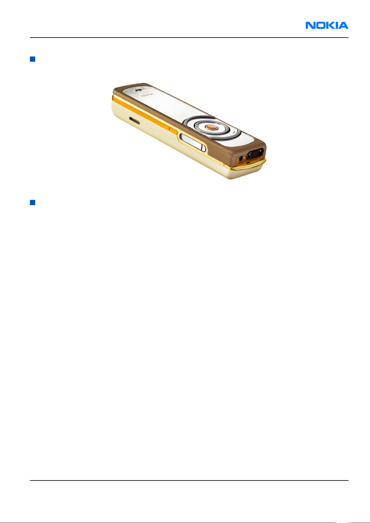
The RM-111 is a triple band transceiver unit designed for the GSM900/1800/1900 networks, including EGSM.
Figure 1 RM-111 product picture
Features
Phone features
Display and keypad features
• Active TFT color display (128x160 pixels/29x35 mm) with 256 K colors.
• 104x208 16 bit colour display
• UI: Rotator, select key, send key, end key and two soft keys
• Subtle mirror surface when phone is in idle
• Light enhanced UI effects
Hardware features
• Internal megapixel camera (2 Mpixel)
• Camera flash
• EasyFlash system connector
• Bluetooth
• FM Radio
• MP3 player
• Internal vibrator
• Integrated hands free (IHF) speaker
• Plug-in SIM (1.8 V and 3.0 V)
• Real time clock
RF features
• Bearers supported: GSM/EGSM
• Tri-band GSM900/1800/1900
• Internal antenna
• Speech codecs: HR, FR, EFR, AMR
Issue 1 COMPANY CONFIDENTIAL Page 1 –5
Copyright © 2005 Nokia. All rights reserved.
Page 18
RM-111
Nokia Customer Care General information
• GPRS/EGPRS: Multislot Class 8
• HSCSD, CSF
Software and UI features
Software features
• ISA OS 8.0s Platform
• Nokia series 40 user interface
UI features
Imaging • Integrated 2.0 megapixel camera
• Up to 4x digital zoom
• Built-in automatic flash mode
• Video recorder and player
Music • FM stereo radio
• Integrated music player for MP3/AAC/M4A formats
Messaging • Multimedia messaging: MMS 1.2 for creating, receiving, editing, and
sending videos and pictures with AMR voice clips
• Text messaging: Supports concatenated SMS, picture messaging, SMS
distribution list
• Nokia Xpress audio messaging: Record your own voice message and send
to compatible devices
Memory functions • 52 MB built-in memory
Connectivity • Bluetooth wireless technology
• Remote over-the-air (OTA) synchronization 1.1.2
• Local synchronization with PC using PC Suite
• Apple iTools compatible - synchronization of photos, audio files, and
video clips using Nokia Collector v1.0
Browsing • WAP 2.0 xHTML/HTML multimode browser
Data transfer • GPRS: Class B, multislot class 10
• HSCSD (high-speed circuit-switched data)/CSD (circuit-switched data)
Digital services • Video streaming services
• Exclusive UI themes
• Supported ringing tone file formats: MP3, AAC, 64-chord/voice
polyphonic MIDI ringing tones
Voice features • Voice dialing
• Voice recorder
• Integrated handsfree speaker
• Enhanced voice command
Page 1 –6 COMPANY CONFIDENTIAL Issue 1
Copyright © 2005 Nokia. All rights reserved.
Page 19
RM-111
General information Nokia Customer Care
Accessories
Table 1 Battery and chargers
Type Name
AC-1 Retractable chargerr
ACP-12 Travel performance charger
BL-8N Battery 700 mAh Li-Ion
Table 2 Car accessories
Type Name
CK-1W Wireless car kit
CK-7W Advanced car kit
HF-6W Wireless plug-in handsfree
LCH-12 Mobile charger (used with CA-44 adapter)
N616 Car kit
Type Name
HDB-5 Boom headset
HDC-5 Headset
HS-7 Dual headset
HS-14 Dual headset
HS-15 Headset
HS-4W Wireless boom headset
HS-11W Wireless headset
HS-13W Wireless image headset
HS-21W Wireless clip-on headset
HS-26W Wireless headset
HS-36W Wireless headset
HS-37W Wireless headset
Table 3 Audio
Issue 1 COMPANY CONFIDENTIAL Page 1 –7
Copyright © 2005 Nokia. All rights reserved.
Page 20

RM-111
Nokia Customer Care General information
(This page left intentionally blank.)
Page 1 –8 COMPANY CONFIDENTIAL Issue 1
Copyright © 2005 Nokia. All rights reserved.
Page 21

Nokia Customer Care
2 — Parts and layouts
Issue 1 COMPANY CONFIDENTIAL Page 2 –1
Copyright © 2005 Nokia. All rights reserved.
Page 22

RM-111
Nokia Customer Care Parts and layouts
(This page left intentionally blank.)
Page 2 –2 COMPANY CONFIDENTIAL Issue 1
Copyright © 2005 Nokia. All rights reserved.
Page 23

RM-111
Parts and layouts Nokia Customer Care
Table of Contents
Exploded view.........................................................................................................................................................2–5
Spare parts overview.............................................................................................................................................2–6
Mechanical parts list...............................................................................................................................................2–7
Swap phones...........................................................................................................................................................2–8
Component parts list..............................................................................................................................................2–8
Component layouts..............................................................................................................................................2–10
List of Tables
Table 4 Mechanical parts list.................................................................................................................................2–7
Table 5 SWAP phones for RM-111.........................................................................................................................2–8
Table 6 Changeable component parts..................................................................................................................2–8
List of Figures
Figure 2 Exploded view..........................................................................................................................................2–5
Figure 3 Spare parts overview..............................................................................................................................2–6
Figure 4 RM-111 component layout, bottom....................................................................................................2–10
Figure 5 RM-111 component layout, top...........................................................................................................2–10
Issue 1 COMPANY CONFIDENTIAL Page 2 –3
Copyright © 2005 Nokia. All rights reserved.
Page 24

RM-111
Nokia Customer Care Parts and layouts
(This page left intentionally blank.)
Page 2 –4 COMPANY CONFIDENTIAL Issue 1
Copyright © 2005 Nokia. All rights reserved.
Page 25
RM-111
Parts and layouts Nokia Customer Care
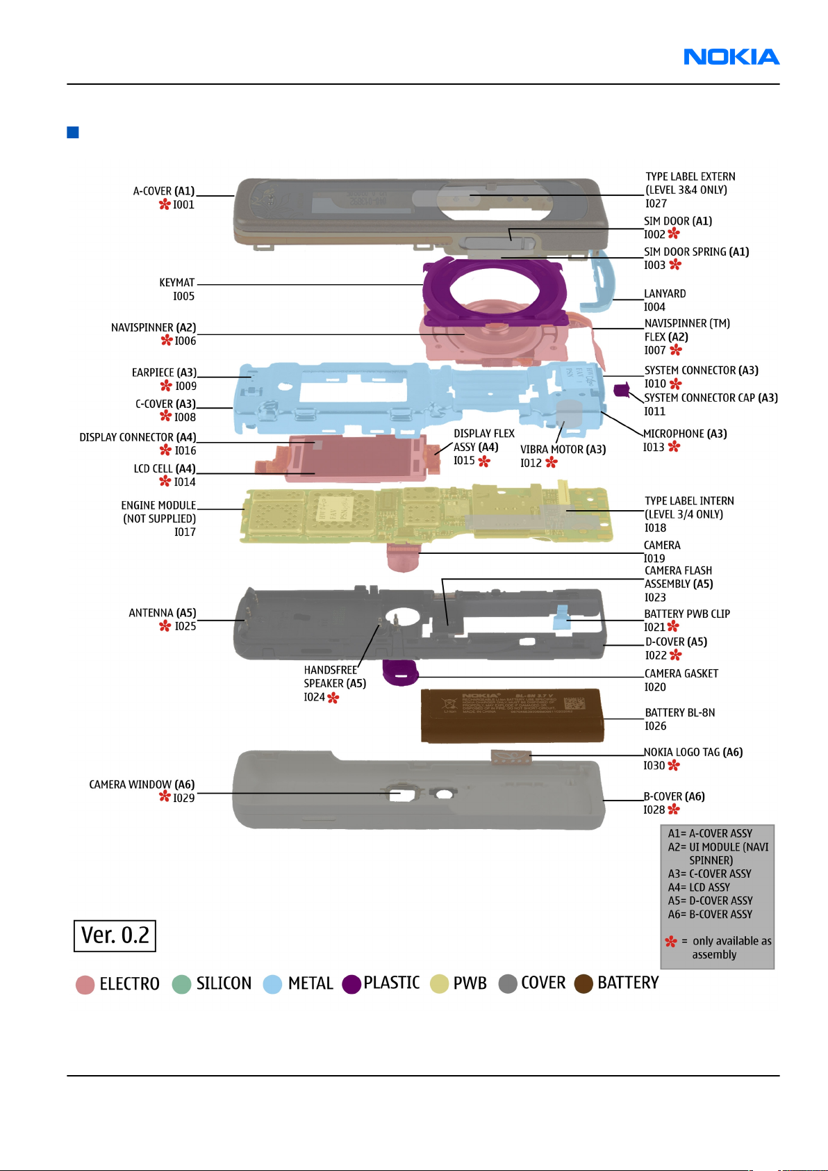
Exploded view
Figure 2 Exploded view
Issue 1 COMPANY CONFIDENTIAL Page 2 –5
Copyright © 2005 Nokia. All rights reserved.
Page 26
RM-111
Nokia Customer Care Parts and layouts
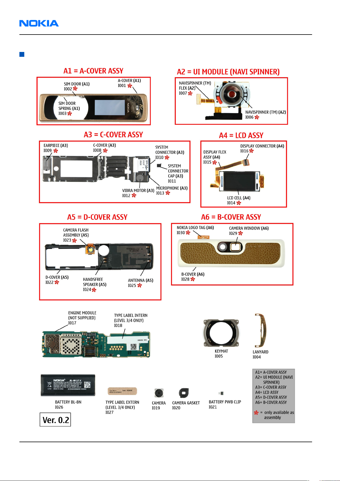
Spare parts overview
Figure 3 Spare parts overview
Page 2 –6 COMPANY CONFIDENTIAL Issue 1
Copyright © 2005 Nokia. All rights reserved.
Page 27
RM-111
Parts and layouts Nokia Customer Care
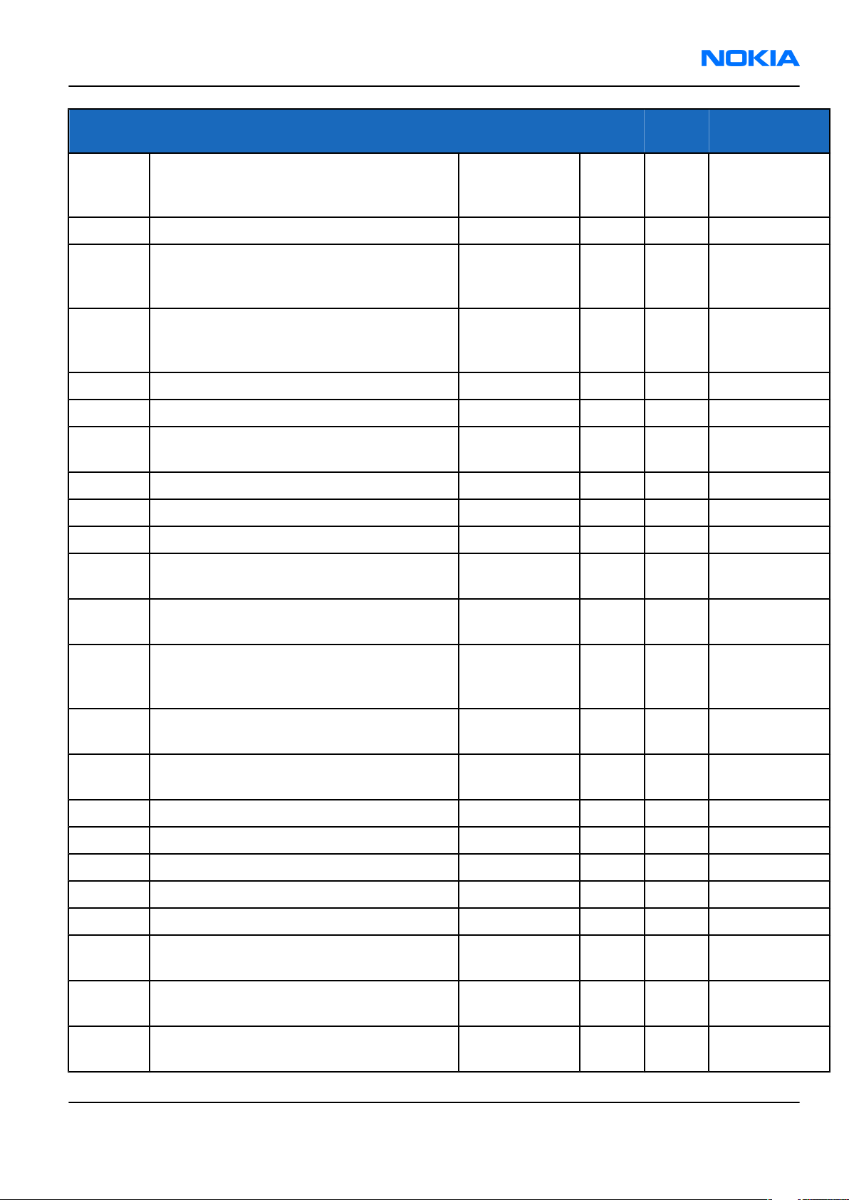
Mechanical parts list
Table 4 Mechanical parts list
Note: For the latest version of the parts lists and for NMP codes, please refer to the Service bulletins.
ITEM REF. QTY PART NAME Comments
* = Not available as spare part
A1 1 A-COVER ASSY Must be replaced after
disassembling
I001* 1 A-COVER
I002* 1 SIM DOOR
I003* 1 SIM DOOR SPRING
I004 1 LANYARD
I005 1 KEYMAT
A2 1 UI MODULE (NAVI SPINNER) Take great care when
disassembling
I006* 1 NAVI SPINNER
I007* 1 NAVI SPINNER FLEX
A3 1 C-COVER ASSY Must be replaced after
disassembling
I008* 1 C-Cover
I009* 1 EARPIECE
I010* 1 SYSTEM CONNECTOR
I011 SYSTEM CONNECTOR CAP For EasyFlash plug
I012* 1 VIBRA MOTOR
I013* 1 MICROPHONE
A4 1 LCD ASSY
I014* 1 LCD CELL
I015* 1 FLEX ASSY
I016* 1 DISPLAY CONNECTOR
A5* 1 ENGINE MODULE Including camera flash
I017* 1 ENGINE MODULE
I018 1 TYPE LABEL INTERN
I019 1 CAMERA
I020 1 CAMERA GASKET Careful when mounting
I021 1 BATTERY PWB CLIP
Issue 1 COMPANY CONFIDENTIAL Page 2 –7
Copyright © 2005 Nokia. All rights reserved.
Page 28
RM-111
Nokia Customer Care Parts and layouts
ITEM REF. QTY PART NAME Comments
A6 1 D-COVER ASSY Must be replaced after
disassembling
I022* 1 D-COVER
I023* 1 CAMERA FLASH ASSEMBLY
I024* 1 HANDS-FREE SPEAKER
I025* 1 ANTENNA
I026 1 BATTERY BL-8N
I027 1 TYPE LABEL EXTERN
A7 1 B-COVER ASSY
I028* 1 B-COVER
I029* 1 CAMERA WINDOW
I030* 1 NOKIA LOGO TAG
I031 1 Pouch & Wriststrap Amber
Swap phones
Table 5 SWAP phones for RM-111
Note: For the latest version of the parts lists and for NMP codes, please refer to the Service bulletins.
SWAP phones for RM-111
N7380 RM-111 SWAP ENGINE UKRAINE
N7380 RM-111 SWAP ENGINE RUSSIA
N7380 RM-111 SWAP ENGINE TURKEY
N7380 RM-111 SWAP ENGINE FRANCE
N7380 RM-111 SWAP ENGINE S&A
N7380 RM-111 SWAP ENGINE E&A
Component parts list
Table 6 Changeable component parts
Note: For the latest version of the parts lists and for NMP codes, please refer to the Service bulletins.
Item ref Name Type PWB
side
D2020 SCH DIODE 30V 200MA VF 0V5 SOD523 Diode T L2
D2021 SCH DIODE 30V 200MA VF 0V5 SOD523 Diode T M2
D6000 BTHFM1.0 ES4 Module Hybrid T N4 Use rework kit
F1000 SM FUSE FF 2A 32V 0402 Fuse And
Protector
Page 2 –8 COMPANY CONFIDENTIAL Issue 1
Copyright © 2005 Nokia. All rights reserved.
B U6 Also change
X/Y Comments
V2000
Page 29
RM-111
Parts and layouts Nokia Customer Care
Item ref Name Type PWB
side
N2080 CURRNT SENS LM3820 USMD10 PB-FREE Power
Management
IC
N2400 VREG 2.85/150MA(LP3987-2.85)USMD5 Analog IC T J2
N2425 REG LM2795TLX-NOPB 2.4X2.0X0.8MM Power
Management
IC
N2480 BUCK/BOOST CONV. REG710NA-5 SOT23 Power
Management
IC
Q2022 MOSFET N 30V 100MA VMT3 FET T L2
Q2700 MOSFET N 30V 100MA VMT3 FET T O6
V2000 TVS DI 1PMT16AT3 16V 175W PWRMITE Diode B O6 Also change
V2020 MFET x2 P 12V 5A 0R028 TSSOP8 FET T K2
V2425 MOSFET N 30V 100MA VMT3 FET T J3
B K3
T J3
T N6
X/Y Comments
F1000
V2426 MOSFET N 30V 100MA VMT3 FET T J4
V2429 TRX2+RX4 N 4K7/47K SOT666 Other
Transistor
X2000 SM BATT CONN 2POL P1893 Battery
Connector
X2005 MODULE ID COMPONENT 2.8X1.8X0.3 Other
Customized
Connector
X2420 SM CONN 2X12F P0.5 PWB/PWB Multipole
Connector
X2460 CONN MULT 20FLT-SM2-GW-TB Multipole
Connector
X2500 Flash connector Spring B M6
X2501 Flash connector Spring B N6
X2502 Flash connector Spring B N6
X2700 SIM CONNECTOR PARIS SIM Connector T Q4
X3320 SM CAMERA MOD SKT 2X8F Socket B K5
Z2430 ASIP EMI/ESD FILTER BGA6 Integrated
Discretes
T T4
B J2
T J5
T T5
T T6
Z2440 ASIP EMI/ESD FILTER BGA6 Integrated
Discretes
Z2460 ASIP 10-CH ESD EMI FILTER BGA25 Integrated
Discretes
Issue 1 COMPANY CONFIDENTIAL Page 2 –9
Copyright © 2005 Nokia. All rights reserved.
T S6
T T5
Page 30
RM-111
Nokia Customer Care Parts and layouts
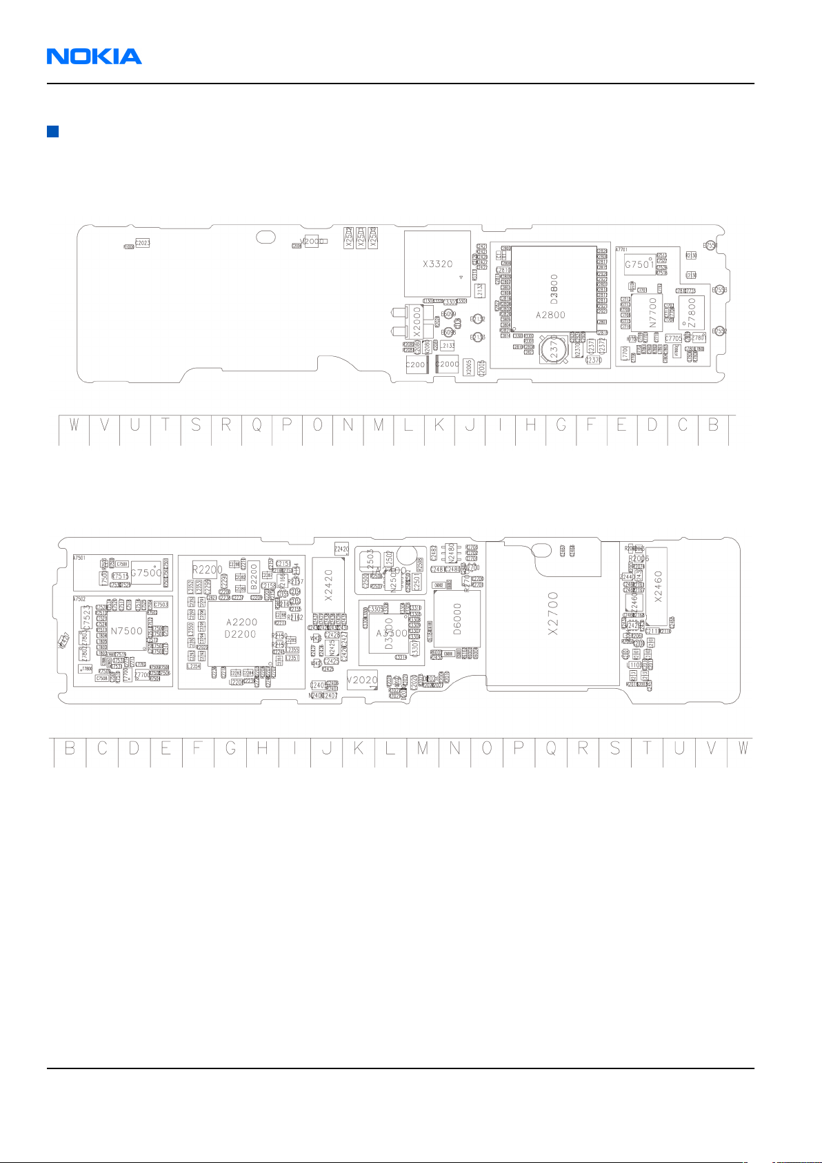
Component layouts
Note: Shielding cans may ONLY be cut open by Repair analysis technicians, and for analysis only.
Component layout, 1qca_07, bottom side
Figure 4 RM-111 component layout, bottom
Component layout, 1qca_07, top side
Figure 5 RM-111 component layout, top
Page 2 –10 COMPANY CONFIDENTIAL Issue 1
Copyright © 2005 Nokia. All rights reserved.
Page 31

Nokia Customer Care
3 — Phoenix service SW
Issue 1 COMPANY CONFIDENTIAL Page 3 –1
Copyright © 2005 Nokia. All rights reserved.
Page 32

RM-111
Nokia Customer Care Phoenix service SW
(This page left intentionally blank.)
Page 3 –2 COMPANY CONFIDENTIAL Issue 1
Copyright © 2005 Nokia. All rights reserved.
Page 33

RM-111
Phoenix service SW Nokia Customer Care
Table of Contents
Service software installation.................................................................................................................................3–5
Phoenix installation steps in brief...................................................................................................................3–5
Installing Phoenix.............................................................................................................................................3–5
Phoenix update installation...........................................................................................................................3–11
Uninstalling Phoenix.......................................................................................................................................3–12
Repairing Phoenix installation......................................................................................................................3–15
Phoenix service software data package overview......................................................................................3–17
Installing Phoenix data package...................................................................................................................3–17
Uninstalling Phoenix data package...............................................................................................................3–22
Service software instructions..............................................................................................................................3–24
Configuring users in Phoenix.........................................................................................................................3–24
Managing connections in Phoenix................................................................................................................3–25
Installing Flash support files for FPS-8* and FLS-4*....................................................................................3–29
Updating FPS-8 Flash prommer software.....................................................................................................3–34
Activating FPS-8...............................................................................................................................................3–36
Deactivating FPS-8..........................................................................................................................................3–37
Updating JBV-1 docking station software....................................................................................................3–38
List of Figures
Figure 6 Dongle not found.....................................................................................................................................3–6
Figure 7 Preparing setup.......................................................................................................................................3–6
Figure 8 Welcome dialog.......................................................................................................................................3–7
Figure 9 Disclaimer text.........................................................................................................................................3–7
Figure 10 Destination folder.................................................................................................................................3–8
Figure 11 Installation status 1..............................................................................................................................3–8
Figure 12 Installation status 2..............................................................................................................................3–9
Figure 13 Registering components 1.................................................................................................................3–10
Figure 14 Restart computer................................................................................................................................3–10
Figure 15 Registering components 2.................................................................................................................3–11
Figure 16 Finish installation................................................................................................................................3–11
Figure 17 Installation interrupted......................................................................................................................3–12
Figure 18 Remove program.................................................................................................................................3–13
Figure 19 Uninstallation status...........................................................................................................................3–14
Figure 20 Finish uninstallation...........................................................................................................................3–14
Figure 21 Restart computer................................................................................................................................3–15
Figure 22 Repair program...................................................................................................................................3–16
Figure 23 Finish repair installation....................................................................................................................3–16
Figure 24 Extracting files.....................................................................................................................................3–18
Figure 25 Continue data package installation..................................................................................................3–18
Figure 26 Data package setup information.......................................................................................................3–19
Figure 27 Data package destination folder.......................................................................................................3–20
Figure 28 Start copying files...............................................................................................................................3–21
Figure 29 Data package installation status.......................................................................................................3–21
Figure 30 Finish data package installation........................................................................................................3–22
Figure 31 Uninstalling Phoenix data package...................................................................................................3–23
Figure 32 Finish data package uninstallation...................................................................................................3–23
Figure 33 Login.....................................................................................................................................................3–24
Figure 34 Add information for new user 1........................................................................................................3–24
Figure 35 Add information for new user 2........................................................................................................3–24
Issue 1 COMPANY CONFIDENTIAL Page 3 –3
Copyright © 2005 Nokia. All rights reserved.
Page 34

RM-111
Nokia Customer Care Phoenix service SW
Figure 36 Login, user configured........................................................................................................................3–25
Figure 37 Phoenix icon........................................................................................................................................3–25
Figure 38 Manage connections...........................................................................................................................3–26
Figure 39 Connections list...................................................................................................................................3–26
Figure 40 Select mode: Manual...........................................................................................................................3–27
Figure 41 FLS virtual port icon............................................................................................................................3–27
Figure 42 Connections list...................................................................................................................................3–28
Figure 43 Connection information.....................................................................................................................3–28
Figure 44 Scan product........................................................................................................................................3–29
Figure 45 Product support module information...............................................................................................3–29
Figure 46 Flash update welcome dialog............................................................................................................3–30
Figure 47 Uninstall flash update package.........................................................................................................3–30
Figure 48 Flash installation interrupted............................................................................................................3–31
Figure 49 Continue flash update.........................................................................................................................3–31
Figure 50 Flash destination folder......................................................................................................................3–32
Figure 51 Flash installation status......................................................................................................................3–33
Figure 52 Finish flash update..............................................................................................................................3–33
Figure 53 Phoenix icon........................................................................................................................................3–34
Figure 54 FPS-8 maintenance.............................................................................................................................3–34
Figure 55 Prommer SW update...........................................................................................................................3–34
Figure 56 Prommer SW update done.................................................................................................................3–35
Figure 57 FPS-8 info window..............................................................................................................................3–35
Figure 58 Flash directory window......................................................................................................................3–36
Figure 59 Box activation......................................................................................................................................3–37
Figure 60 Deactivation warning.........................................................................................................................3–37
Figure 61 Extracting JBV-1 update files..............................................................................................................3–38
Figure 62 JBV-1 update information..................................................................................................................3–39
Figure 63 JBV-1 update destination folder........................................................................................................3–39
Figure 64 Select installation: Full.......................................................................................................................3–40
Figure 65 Select program folder.........................................................................................................................3–40
Figure 66 Finish JBV-1 update installation........................................................................................................3–41
Figure 67 Checking JBV-1 SW version.................................................................................................................3–42
Figure 68 JBV-1 update directory window.........................................................................................................3–42
Figure 69 JBV-1 SW update done........................................................................................................................3–42
Figure 70 JBV-1 SW status...................................................................................................................................3–42
Page 3 –4 COMPANY CONFIDENTIAL Issue 1
Copyright © 2005 Nokia. All rights reserved.
Page 35

RM-111
Phoenix service SW Nokia Customer Care
Service software installation
Phoenix installation steps in brief
Phoenix is the DCT-4 generation service software for reprogramming, testing and tuning the phone.
To install Phoenix, you need to:
• Connect a DK2 Dongle or FLS-4S POS Flash Device
• Install the Phoenix Service SW
• Install the Data Package for Phoenix
• Configure users
• Manage connection settings (depends on the tools you are using)
Phoenix is now ready for FLS-4S Point Of Sales Flash Device use.
If you use FPS-8:
• Update FPS-8 SW
• Activate FPS-8
• Update JBV-1 Docking Station SW (only when needed)
Phoenix is now ready to be used with FPS-8 flash prommer and other tools as well.
The Phoenix Service Software installation contains:
• Service software support for all phone models included in the package
• Flash update package files for FPS-8* and FLS-4S programming devices
• All needed drivers for:
• DK2 dongle
• FLS-4S point of sales flash device
• USB devices
Note: Separate installation packages for flash update files and drivers are also available, but it is
not necessary to use them unless updates appear between Phoenix Service SW releases. If separate
update packages are used, they should be used after Phoenix and data packages have been installed.
Supported operating systems
• Windows 2000 and XP.
Hardware requirements for using Phoenix
• Minimum: Processor 300 MHz, RAM memory 64 MB, disk space 100 MB.
• Recommended for Windows 2000: Processor 700 MHz, RAM memory 256 MB, disk space 150 MB.
Installing Phoenix
Before you begin
• Check that a Dongle is attached to the parallel port of your computer.
• Download the installation package (for example,
computer (in
• Close all other programs.
Issue 1 COMPANY CONFIDENTIAL Page 3 –5
C:\TEMP
, for instance).
Copyright © 2005 Nokia. All rights reserved.
phoenix_service_sw_a15_2004_24_7_55.exe
) to your
Page 36

RM-111
Nokia Customer Care Phoenix service SW
• Run the application file (for example,
instructions on the screen.
Note: Administrator rights may be required to be able to install Phoenix depending on the operating
system.
If uninstalling or rebooting is needed at any point, you will be prompted by the Install Shield program.
phoenix_service_sw_a15_2004_24_7_55.exe
) and follow the
Context
If at any point during installation you get this message, Dongle is not found and installation cannot continue:
Figure 6 Dongle not found
Possible reasons may be a defective or too old PKD-1 Dongle (a new dongle has a six digit serial number).
Check the COM/parallel ports used first! After correcting the problem the installation can be restarted.
For more detailed information, please refer to Phoenix Help files. Each feature in Phoenix has its own Help
function, which can be activated while running the program. Press the F1 key or the Help button to activate
a Help file.
Steps
1. Run the
phoenix_service_sw_a15_2004_24_7_55.exe
to start installation. Install Shield prepared the setup.
Figure 7 Preparing setup
Page 3 –6 COMPANY CONFIDENTIAL Issue 1
Copyright © 2005 Nokia. All rights reserved.
Page 37

RM-111
Phoenix service SW Nokia Customer Care
Install Shield will prepare.
2. Click Next in Welcome dialog to continue.
3. Read the disclaimer carefully.
Figure 8 Welcome dialog
Figure 9 Disclaimer text
Issue 1 COMPANY CONFIDENTIAL Page 3 –7
Copyright © 2005 Nokia. All rights reserved.
Page 38

RM-111
Nokia Customer Care Phoenix service SW
4. Choose destination folder. The default folder
click Next to continue. You may choose another location by selecting Browse (not recommended).
C:\ProgramFiles\Nokia\Phoenix
is recommended. Then
Figure 10 Destination folder
5. Wait for the components to be copied. The progress of the setup is shown in the
Setup Status
window.
Figure 11 Installation status 1
Page 3 –8 COMPANY CONFIDENTIAL Issue 1
Copyright © 2005 Nokia. All rights reserved.
Page 39

RM-111
Phoenix service SW Nokia Customer Care
6. Wait for the drivers to be installed and updated.
The process may take several minutes to complete.
If the operating system does not require rebooting (Windows 2000, XP) the PC components are registered
right away.
Figure 12 Installation status 2
Issue 1 COMPANY CONFIDENTIAL Page 3 –9
Copyright © 2005 Nokia. All rights reserved.
Page 40

RM-111
Nokia Customer Care Phoenix service SW
Figure 13 Registering components 1
If the operating system requires restarting your computer (Windows 98, SE, ME) the Install Shield Wizard
will tell you about it. Select Yes... to reboot the PC immediately and No... to reboot the PC manually
afterwards.
Figure 14 Restart computer
Page 3 –10 COMPANY CONFIDENTIAL Issue 1
Copyright © 2005 Nokia. All rights reserved.
Page 41

RM-111
Phoenix service SW Nokia Customer Care
After the reboot, components are registered and Phoenix is ready for use.
Note: Phoenix does not work, if components have not been registered.
Figure 15 Registering components 2
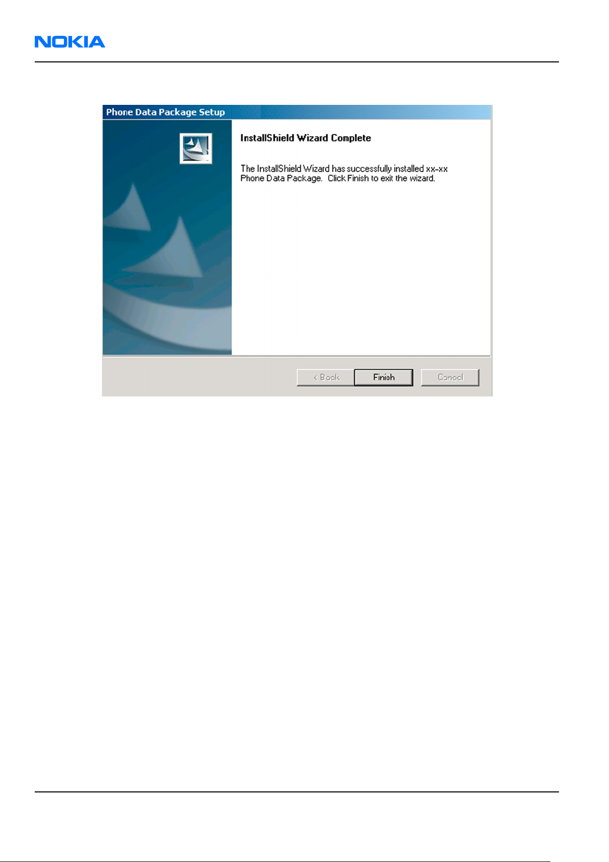
7. Click Finish to end installation.
Figure 16 Finish installation
Phoenix is now ready for use.
Next action
Before using Phoenix Service Software, you must:
• install phone model specific data package for Phoenix, and
• configure users and connections.
FPS-8* can be used after updating its Flash Update Package files.
Phoenix update installation
If you already have the Phoenix Service SW installed on your computer, sooner or later there will be need to
update it when new versions are released.
Always use the latest available versions of both the Phoenix Service SW and the phone-specific Data Package.
Instructions can be found in phone model specific Technical Bulletins and Phone Data Package readme.txt
files (shown during installation).
To update the Phoenix Service Software you need to take exactly the same steps as when installing it for the
first time:
Issue 1 COMPANY CONFIDENTIAL Page 3 –11
Copyright © 2005 Nokia. All rights reserved.
Page 42

RM-111
Nokia Customer Care Phoenix service SW
• Download the installation package to your computer hard disk.
• Close all other programs.
• Run the application file (for example, phoenix_service_sw_a15_2004_24_7_55.exe).
• New version of Phoenix will be installed.
• Driver versions will be checked and updated.
When you update Phoenix from old to new version (for example, a14_2004_16_4_47 to a15_2004_24_7_55),
the update will take place automatically without uninstallation.
If you try to update the Phoenix Service Software with the same version that you already have (for example,
a15_2004_24_7_55 to a15_2004_24_7_55) you are asked if you want to uninstall the version of Phoenix you
have on your PC. In this case you can choose between total uninstallation and repair just like when you choose
to uninstall Phoenix service software from the Windows Control panel.
If you try to install an older version (for example, downgrade from a15_2004_24_7_55 to a14_2004_16_4_47),
installation will be interrupted.
Always follow the instructions on the screen.
Figure 17 Installation interrupted
Uninstalling Phoenix
Context
Uninstallation can be done manually from Windows Control Panel→Add/Remove Programs .
Page 3 –12 COMPANY CONFIDENTIAL Issue 1
Copyright © 2005 Nokia. All rights reserved.
Page 43

RM-111
Phoenix service SW Nokia Customer Care
Steps
1. Choose Phoenix Service Software→Add/Remove→Remove to uninstall Phoenix.
Figure 18 Remove program
The progress of the uninstallation is shown.
Issue 1 COMPANY CONFIDENTIAL Page 3 –13
Copyright © 2005 Nokia. All rights reserved.
Page 44

RM-111
Nokia Customer Care Phoenix service SW
Figure 19 Uninstallation status
2. If the operating system does not require rebooting, click Finish to complete.
Else, Install Shield Wizard will tell you about it. Select Yes... to reboot the PC immediately and No... to
reboot the PC manually afterwards.
Figure 20 Finish uninstallation
Page 3 –14 COMPANY CONFIDENTIAL Issue 1
Copyright © 2005 Nokia. All rights reserved.
Page 45

RM-111
Phoenix service SW Nokia Customer Care
Figure 21 Restart computer
Repairing Phoenix installation
Context
If you experience any problems with the service software, or suspect that files have been lost, you can use
the repair function before completely reinstalling Phoenix.
Note: The original installation package (for example,
must be found on your PC when you run the repair setup.
phoenix_service_sw_a15_2004_24_7_55.exe
Steps
1. Open Windows Control Panel→Add/Remove Programs .
2. Select Phoenix Service Software→Add/Remove .
3. In the following view, choose Repair.
Phoenix will now reinstall components and register them. The procedure is the same as in the update
installation.
)
Issue 1 COMPANY CONFIDENTIAL Page 3 –15
Copyright © 2005 Nokia. All rights reserved.
Page 46

RM-111
Nokia Customer Care Phoenix service SW
4. Click Finish to complete repair.
Figure 22 Repair program
Figure 23 Finish repair installation
Page 3 –16 COMPANY CONFIDENTIAL Issue 1
Copyright © 2005 Nokia. All rights reserved.
Page 47

RM-111
Phoenix service SW Nokia Customer Care
Phoenix service software data package overview
Each product has its own data package (DP). This contains all product-specific data files to make the Phoenix
Service Software and tools usable with a certain phone model:
• Product software binary files
• Files for type label printing
• Validation file for the faultlog repair data reporting system
• All product-specific configuration files for Phoenix Service Software components
Data files are stored under C:\Program Files\Nokia\Phoenix (default).
Installing Phoenix data package
Before you begin
1 Verify that The data package contains all product-specific data to make the Phoenix Service Software and
tools usable with a certain phone model.
2 Check that the dongle is attached to the parallel port of your computer.
3 Install Phoenix Service SW.
4 Download the installation package (for example,
in
C:\TEMP
).
RH-13_dp_EA_v_1_0.exe
) to your computer (for example,
5 Close all other programs.
6 Run the application file (for example,
If you already have the Phoenix Service SW installed on your computer, you will need to update it when a
new version is released.
Note: Very often the Phoenix Service SW and the phone-specific data package for Phoenix come in
pairs, meaning that a certain version of Phoenix can only be used with a certain version of the data
package. Always use the latest available versions of both. Instructions can be found in phone model
specific Technical Bulletins and
RH-13_dp_EA_ v_1_0.exe
readme.txt
files of the data packages.
) and follow the instructions on the screen.
Steps
1. To start installation, run the application file (for example,
RH-13_dp_EA_ v_1_0.exe
).
Issue 1 COMPANY CONFIDENTIAL Page 3 –17
Copyright © 2005 Nokia. All rights reserved.
Page 48

RM-111
Nokia Customer Care Phoenix service SW
2. Click Next, and wait for the installation files to be extracted.
3. Click Next to continue.
Figure 24 Extracting files
Figure 25 Continue data package installation
Page 3 –18 COMPANY CONFIDENTIAL Issue 1
Copyright © 2005 Nokia. All rights reserved.
Page 49

RM-111
Phoenix service SW Nokia Customer Care
In this view you can see the contents of the data package. Read the text carefully. There should be
information about the Phoenix version required with this data package.
Click Next to continue.
Figure 26 Data package setup information
Issue 1 COMPANY CONFIDENTIAL Page 3 –19
Copyright © 2005 Nokia. All rights reserved.
Page 50

RM-111
Nokia Customer Care Phoenix service SW
4. Confirm location and click Next to continue.
Figure 27 Data package destination folder
The install shield checks where the Phoenix application is installed and the directory is shown.
Click Next to continue.
5. Click Next to start copying the files.
Phone model specific files will be installed. Please wait.
Page 3 –20 COMPANY CONFIDENTIAL Issue 1
Copyright © 2005 Nokia. All rights reserved.
Page 51

RM-111
Phoenix service SW Nokia Customer Care
Figure 28 Start copying files
Figure 29 Data package installation status
Issue 1 COMPANY CONFIDENTIAL Page 3 –21
Copyright © 2005 Nokia. All rights reserved.
Page 52
RM-111
Nokia Customer Care Phoenix service SW
6. Click Finish to complete the installation.
Figure 30 Finish data package installation
You now have all phone model specific files installed in your Phoenix Service SW.
Next action
Phoenix can be used, for example, for flashing phones and printing type labels. But first you must:
• configure users, and
• manage connections.
FLS-4S can be used right away.
FPS-8* can be used after updating Flash Update Package files.
Uninstalling Phoenix data package
Context
If you try to install the same version of Phoenix data package that you already have, you are asked if you
want to uninstall the version you have on your PC. Older versions of data packages don´t need to be
uninstalled unless instructions to do so are given in the
concerning the release. Please read all related documents carefully.
readme.txt
file of the data package and bulletins
Page 3 –22 COMPANY CONFIDENTIAL Issue 1
Copyright © 2005 Nokia. All rights reserved.
Page 53

RM-111
Phoenix service SW Nokia Customer Care
Steps
1. Click OK to uninstall, Cancel if you don’t want to uninstall.
Figure 31 Uninstalling Phoenix data package
2. Once the previously installed data package is uninstalled, click Finish.
Figure 32 Finish data package uninstallation
Alternative steps
• Uninstallation can also be done manually from
Windows Control Panel→Add/Remove Programs→xx-xx (* Phone Data Package) . (*= type
designator of the phone
Next action
Run the installation package again to continue installation from the beginning.
Issue 1 COMPANY CONFIDENTIAL Page 3 –23
Copyright © 2005 Nokia. All rights reserved.
Page 54

RM-111
Nokia Customer Care Phoenix service SW
Service software instructions
Configuring users in Phoenix
Steps
1. Start Phoenix Service SW and log in.
If your user ID is already configured, choose it from the dropdown list and click OK. To add a new user or
edit existing ones click Maintain.
Figure 33 Login
2. Choose New to add information for a new user.
Figure 34 Add information for new user 1
3. Type in your name and initials and click OK.
Figure 35 Add information for new user 2
Page 3 –24 COMPANY CONFIDENTIAL Issue 1
Copyright © 2005 Nokia. All rights reserved.
Page 55

RM-111
Phoenix service SW Nokia Customer Care
A new user is now created.
4. Click OK.
You are now able to login with this user name.
5. Click OK.
Figure 36 Login, user configured
Managing connections in Phoenix
Steps
1. Start
Phoenix Service SW
and log in.
Figure 37 Phoenix icon
Issue 1 COMPANY CONFIDENTIAL Page 3 –25
Copyright © 2005 Nokia. All rights reserved.
Page 56

RM-111
Nokia Customer Care Phoenix service SW
2. Choose File→Manage Connections .
Figure 38 Manage connections
Existing connections can be selected, edited, deleted, and new ones created by using this dialog.
Figure 39 Connections list
3. Click Add to add a new connection, and select if you want to create it manually or by using the Connection
Wizard.
In the following dialogs you will be asked to select settings for the connection. If you use the Wizard,
connect the tools and a phone to your PC and the wizard will automatically try to configure the correct
connection.
Page 3 –26 COMPANY CONFIDENTIAL Issue 1
Copyright © 2005 Nokia. All rights reserved.
Page 57

RM-111
Phoenix service SW Nokia Customer Care
4. Select Manual mode, and click Next to continue.
Figure 40 Select mode: Manual
i For FLS-4S POS Flash Device, choose the following connection settings:
• Media: FBUS
• COM Port: Virtual COM Port used by FLS-4
Note: ALWAYS check this. Go to
Windows→Control Panel→FLS Virtual Port→Configuration .
Figure 41 FLS virtual port icon
ii For FPS-8 Flash Prommer, choose the following connection settings:
• Media: FPS-8
Issue 1 COMPANY CONFIDENTIAL Page 3 –27
Copyright © 2005 Nokia. All rights reserved.
Page 58

RM-111
Nokia Customer Care Phoenix service SW
• Port Num: COM Port where FPS-8 is connected
• COMBOX_DEF_MEDIA: FBUS
5. Click Finish to complete the configuration.
6. Activate the connection you want to use by clicking it, use up/down arrows to move it on top of the list,
and click Apply.
Figure 42 Connections list
The connection is now selected and can be used after closing the
Selected connection will be shown on the right hand bottom corner of the screen.
Figure 43 Connection information
Manage Connections
window.
Page 3 –28 COMPANY CONFIDENTIAL Issue 1
Copyright © 2005 Nokia. All rights reserved.
Page 59

RM-111
Phoenix service SW Nokia Customer Care
7. To use the selected connection, connect the phone to Phoenix with correct service tools, make sure that
it is switched on and select Scan Product.
Figure 44 Scan product
When a product is found, Phoenix will load product support. Name of the loaded product support module
and its version information will be shown on the bottom of the screen.
Figure 45 Product support module information
Installing Flash support files for FPS-8* and FLS-4*
Before you begin
Note: This is a separate installation package.
• Install Phoenix Service SW.
• Install phone model specific data package for Phoenix.
• The flash support files are delivered in the same installation package with Phoenix data packages or newer
Phoenix packages since September 2003.
• Normally it is enough to install Phoenix and the phone-specific data package because the Phoenix
installation always includes the latest flash update package files for FLS-4S/FPS-8*.
• A separate installation package for flash support files is available, and the files can be updated according
to this instruction if updates appear between Phoenix/data package releases.
Issue 1 COMPANY CONFIDENTIAL Page 3 –29
Copyright © 2005 Nokia. All rights reserved.
Page 60

RM-111
Nokia Customer Care Phoenix service SW
Context
If you are not using a separate installation package, you can skip this section and continue with FPS-8 Flash
prommer SW update (page 3–34) after installing a new phone data package.
Steps
1. Start by double clicking
flash_update_03_13_001.exe
to begin installation.
Figure 46 Flash update welcome dialog
2. If the same version of Flash Update package already exists, and you want to reinstall it, the previous
package is first uninstalled. Run the installation again.
Figure 47 Uninstall flash update package
If you try to downgrade the existing version to older ones, the setup will be aborted. If you really want
to downgrade, uninstall newer files manually from Control Panel and then rerun the installation again.
Page 3 –30 COMPANY CONFIDENTIAL Issue 1
Copyright © 2005 Nokia. All rights reserved.
Page 61

RM-111
Phoenix service SW Nokia Customer Care
Figure 48 Flash installation interrupted
If an older version exists on your PC and it needs to be updated, click Next to continue installation.
Figure 49 Continue flash update
Issue 1 COMPANY CONFIDENTIAL Page 3 –31
Copyright © 2005 Nokia. All rights reserved.
Page 62

RM-111
Nokia Customer Care Phoenix service SW
3. It is highly recommended to install the files to the default destination folder
\Phoenix
. Click Next to continue.
C:\Program Files\Nokia
Figure 50 Flash destination folder
When installing the flash update files for the first time you may choose another location by selecting
Browse. However, this is not recommended.
Installation will continue.
Page 3 –32 COMPANY CONFIDENTIAL Issue 1
Copyright © 2005 Nokia. All rights reserved.
Page 63

RM-111
Phoenix service SW Nokia Customer Care
Figure 51 Flash installation status
4. Choose Finish to complete the installation procedure.
Figure 52 Finish flash update
Next action
FLS-4 can be used right after the Flash Update Package is installed.
Issue 1 COMPANY CONFIDENTIAL Page 3 –33
Copyright © 2005 Nokia. All rights reserved.
Page 64

RM-111
Nokia Customer Care Phoenix service SW
FPS-8* flash prommer must be updated using Phoenix!
Updating FPS-8 Flash prommer software
Steps
1. Start
2. Choose Flashing→FPS-8 Maintenance .
Phoenix Service Software
and log in, manage connection correctly for the FPS-8* flash prommer.
Figure 53 Phoenix icon
Figure 54 FPS-8 maintenance
Note: Screen shots may be different depending on the Phoenix version used and the connected
components.
3. When the new FPS-8 flash update package is installed to computer you will be asked to update the files
to your FPS-8 Prommer. Select Yes to update files.
Figure 55 Prommer SW update
Page 3 –34 COMPANY CONFIDENTIAL Issue 1
Copyright © 2005 Nokia. All rights reserved.
Page 65

RM-111
Phoenix service SW Nokia Customer Care
4. Wait until you are notified that update has been successful; the procedure will take a couple of minutes.
Click OK to close the
View after successful prommer software update:
FPS-8 Maintenance
Figure 56 Prommer SW update done
window.
Figure 57 FPS-8 info window
Issue 1 COMPANY CONFIDENTIAL Page 3 –35
Copyright © 2005 Nokia. All rights reserved.
Page 66

RM-111
Nokia Customer Care Phoenix service SW
Alternative steps
• FPS-8 SW can also be updated by pressing Update button and selecting appropriate
\Program Files\Nokia\Phoenix\Flash
• All files can be loaded separately to FPS-8. To do this, just press the right mouse button in the
files
window and select the file type to be loaded.
.
Figure 58 Flash directory window
fps8upd.ini
Flash box
file in
C:
More information can be found in Phoenix Help.
Activating FPS-8
Context
Before FPS-8 can be successfully used for phone programming, it must first be activated.
First fill in the
When activation file is received (for example,
\BoxActivation
FPS-8 activation request
directory on your computer (this directory is created when
sheet in the FPS-8 sales package, and follow the instructions given.
00000.in
), copy it to the
C:\ProgramFiles\Nokia\Phoenix
Phoenix
is installed).
Steps
1. Start
2. Choose Flashing→Prommer Maintenance .
3. In the
4. To find the activation file, click Browse.
Phoenix
service software.
Prommer Maintenance
window, click Activate.
Page 3 –36 COMPANY CONFIDENTIAL Issue 1
Copyright © 2005 Nokia. All rights reserved.
Page 67

RM-111
Phoenix service SW Nokia Customer Care
5. To activate the prommer, select the activation file and click Open.
Figure 59 Box activation
6. To complete the activation, restart FPS-8.
Deactivating FPS-8
Context
If there is, for example, a need to send the FPS-8 box for repair, it must be deactivated first.
Steps
1. Start
2. Choose Flashing→Prommer Maintenance .
3. In the
4. To confirm the deactivation, click Yes.
Phoenix
service software.
Prommer Maintenance
window, click Deactivate.
Figure 60 Deactivation warning
The box is deactivated.
5. To complete the deactivation, restart FPS-8.
Issue 1 COMPANY CONFIDENTIAL Page 3 –37
Copyright © 2005 Nokia. All rights reserved.
Page 68

RM-111
Nokia Customer Care Phoenix service SW
Updating JBV-1 docking station software
Before you begin
The JBV-1 docking station contains software (firmware) which can be updated. You need the following
equipment to update the software:
• PC with USB connection
• operating system supporting USB (Not Win 95 or NT)
• USB Cable (can be purchased from shops or suppliers providing PC hardware and accessories)
• JBV-1 docking station
• external power supply (11-16V)
Before installation:
• Download
site.
• Close all other programs.
• Follow instructions on the screen.
Jbv1_18_update.zip
file to your computer (in
C:\TEMP
for example) from your download web
Context
The JBV-1 docking station is a common tool for all DCT-4 generation products. In order to make the JBV-1
usable with different phone models, a phone-specific docking station adapter is used.
Steps
1. Run
Jbv1_18_update.zip
Note: DO NOT CONNECT THE USB CABLE/JBV-1 TO YOUR COMPUTER YET!
Files needed for JBV-1 package setup program will be extracted.
file and start software installation by double clicking
Figure 61 Extracting JBV-1 update files
Setup.exe
.
Page 3 –38 COMPANY CONFIDENTIAL Issue 1
Copyright © 2005 Nokia. All rights reserved.
Page 69

RM-111
Phoenix service SW Nokia Customer Care
2. Read the instructions in the dialog box and click Next to continue.
Figure 62 JBV-1 update information
3. Accept the suggested destination folder for installing the JBV-1 SW Package, and click Next to continue.
Figure 63 JBV-1 update destination folder
4. Select Full installation and click Next to continue.
Issue 1 COMPANY CONFIDENTIAL Page 3 –39
Copyright © 2005 Nokia. All rights reserved.
Page 70

RM-111
Nokia Customer Care Phoenix service SW
Figure 64 Select installation: Full
5. A program folder is created and the software files are installed there. Click Next to continue.
Figure 65 Select program folder
Page 3 –40 COMPANY CONFIDENTIAL Issue 1
Copyright © 2005 Nokia. All rights reserved.
Page 71

RM-111
Phoenix service SW Nokia Customer Care
6. Click Finish to complete the installation.
Figure 66 Finish JBV-1 update installation
7. Connect the USB cable/JBV-1 to your computer. Connect power to JBV-1 (11-16V DC) from an external
power supply, then connect the USB Cable between the JBV-1 USB connector and the PC.
8. Install or update the JBV-1 USB drivers which are delivered with the JBV-1 SW installation package.
The drivers can be found in
• If there is no previously installed JBV-1 Firmware update package installed on your computer,
Windows will detect connected USB cable and detect drivers for new HW. You will be prompted about
this, please follow the instructions and allow Windows to search and install the best drivers available.
• If there is a previously installed JBV-1 Firmware update package (v.17 or older) on your computer,
please update the JBV-1 USB driver. Please see the
Firmware Update\JBV-1USB driver
After you have installed or updated the JBV-1 USB driver, the actual JBV-1 SW update can begin.
9. Go to folder
Update SW by double clicking
JBV-1 Firmware update starts and shows current status of the connected JBV-1. If firmware version read
from your JBV-1 is not the latest one available (v.17 or older), it needs to be updated to version 18 by
clicking Update Firmware.
C:\Program Files\Nokia\JBV-1 Firmware Update\JBV-1 Firmware Update
C:\Program Files\Nokia\ JBV-1 Firmware Update\JBV-1USB driver
folder for instructions on how to update the JBV-1 USB Driver.
fwup.exe
readme.txt
.
file in
C:\Program Files\Nokia\JBV-1
and start JBV-1
Issue 1 COMPANY CONFIDENTIAL Page 3 –41
Copyright © 2005 Nokia. All rights reserved.
Page 72

RM-111
Nokia Customer Care Phoenix service SW
10. Choose Refresh Status to check the SW version.
Figure 67 Checking JBV-1 SW version
11. Choose file JBV1v18.CDE and click Open to update your JBV-1 to a new version (v.18).
Figure 68 JBV-1 update directory window
Wait until you hear a "click" from the JBV-1.
The older SW file
installed on your computer.
12. Click OK to see the current JBV-1 status (after a successful update).
JBV1v17.CDE
is visible in this view only if the previous JBV-1 SW package has been
Figure 69 JBV-1 SW update done
Figure 70 JBV-1 SW status
Page 3 –42 COMPANY CONFIDENTIAL Issue 1
Copyright © 2005 Nokia. All rights reserved.
Page 73

RM-111
Phoenix service SW Nokia Customer Care
You have now updated the software of your JBV-1 docking station and it is ready for use.
Next action
If you have several docking stations you need to update, disconnect the power and USB cables from the
previous one and connect them to the next docking station. First, click Refresh Status to see the current SW
version and then Update Firmware to update the software.
After you have updated all docking stations, close the
JBV-1 Firmware Update
dialog box.
Issue 1 COMPANY CONFIDENTIAL Page 3 –43
Copyright © 2005 Nokia. All rights reserved.
Page 74

RM-111
Nokia Customer Care Phoenix service SW
(This page left intentionally blank.)
Page 3 –44 COMPANY CONFIDENTIAL Issue 1
Copyright © 2005 Nokia. All rights reserved.
Page 75

Nokia Customer Care
4 — Service tools and concepts
Issue 1 COMPANY CONFIDENTIAL Page 4 –1
Copyright © 2005 Nokia. All rights reserved.
Page 76

RM-111
Nokia Customer Care Service tools and concepts
(This page left intentionally blank.)
Page 4 –2 COMPANY CONFIDENTIAL Issue 1
Copyright © 2005 Nokia. All rights reserved.
Page 77

RM-111
Service tools and concepts Nokia Customer Care
Table of Contents
Service tools............................................................................................................................................................4–5
ACF-8...................................................................................................................................................................4–5
AXS-4...................................................................................................................................................................4–5
CA-10DS...............................................................................................................................................................4–5
CA-28DS...............................................................................................................................................................4–5
CA-31D................................................................................................................................................................4–6
CA-41PS...............................................................................................................................................................4–6
CA-52PS...............................................................................................................................................................4–6
CA-53...................................................................................................................................................................4–6
CA-5S...................................................................................................................................................................4–7
CA-65DS...............................................................................................................................................................4–7
CA-66DS...............................................................................................................................................................4–7
CA-67DS...............................................................................................................................................................4–7
DA-60..................................................................................................................................................................4–8
DAU-9S................................................................................................................................................................4–8
FLC-2....................................................................................................................................................................4–8
FLS-4S..................................................................................................................................................................4–9
FPS-10.................................................................................................................................................................4–9
JBV-1...................................................................................................................................................................4–9
MJ-84.................................................................................................................................................................4–10
PCS-1.................................................................................................................................................................4–10
PKD-1................................................................................................................................................................4–10
RJ-97.................................................................................................................................................................4–10
SA-41.................................................................................................................................................................4–11
SRT-6.................................................................................................................................................................4–11
SS-45.................................................................................................................................................................4–11
SX-4...................................................................................................................................................................4–11
XCS-1.................................................................................................................................................................4–12
XCS-4.................................................................................................................................................................4–12
XRF-1.................................................................................................................................................................4–12
Service concepts...................................................................................................................................................4–13
Service concepts for RM-111..........................................................................................................................4–13
List of Figures
Figure 71 Service concept: Go/Nogo test...........................................................................................................4–13
Figure 72 Service concept: Easy Flash................................................................................................................4–14
Figure 73 Service concept: POS flash with FPS-8...............................................................................................4–15
Figure 74 Service concept: POS flash with FPS-10.............................................................................................4–16
Figure 75 Service concept: Module jig concept with FPS-8 flash prommer....................................................4–17
Figure 76 Service concept: Module jig concept with FPS-10 flash prommer.................................................4–18
Figure 77 Service concept: Module jig service concept....................................................................................4–19
Issue 1 COMPANY CONFIDENTIAL Page 4 –3
Copyright © 2005 Nokia. All rights reserved.
Page 78

RM-111
Nokia Customer Care Service tools and concepts
(This page left intentionally blank.)
Page 4 –4 COMPANY CONFIDENTIAL Issue 1
Copyright © 2005 Nokia. All rights reserved.
Page 79

RM-111
Service tools and concepts Nokia Customer Care
Service tools
The table below gives a short overview of service tools that can be used for testing, error analysis and repair
of product RM-111, refer to various concepts.
ACF-8 Universal power
supply
ACF-8 universal power supply is used to power FPS-8. ACF-8 has 6V DC
and 2.1A output.
AXS-4 Service cable The AXS-4 D9-D9 service cable is used to connect two 9 pin D
connectors for example between PC and FPS-8.
The cable length is 2 meters.
CA-10DS Bi-directional
Parallel Cable
Bi-Directional parallel cable included in FPS-8 sales pack.
CA-28DS Service data cable The CA-28DS service cable is used to connect FLS-4S to the POS flash
adapter for supplying a controlled operating voltage and data
connection.
Note: Old XCS-1 cable can be used as well.
Issue 1 COMPANY CONFIDENTIAL Page 4 –5
Copyright © 2005 Nokia. All rights reserved.
Page 80

RM-111
Nokia Customer Care Service tools and concepts
CA-31D USB cable The CA-31D USB cable is used to connect FPS-10 or FPS-11 to a PC. It is
included in the FPS-10 and FPS-11 sales packages.
CA-41PS Power cable Power cable for connection of e.g. the JBV-1 docking station to the
FPS-10 prommer box.
CA-52PS Service Battery Cable EM calibration JBV-1 to phone.
CA-53 USB connectivity
cable
USB to Pop-PortTM connector cable.
Page 4 –6 COMPANY CONFIDENTIAL Issue 1
Copyright © 2005 Nokia. All rights reserved.
Page 81
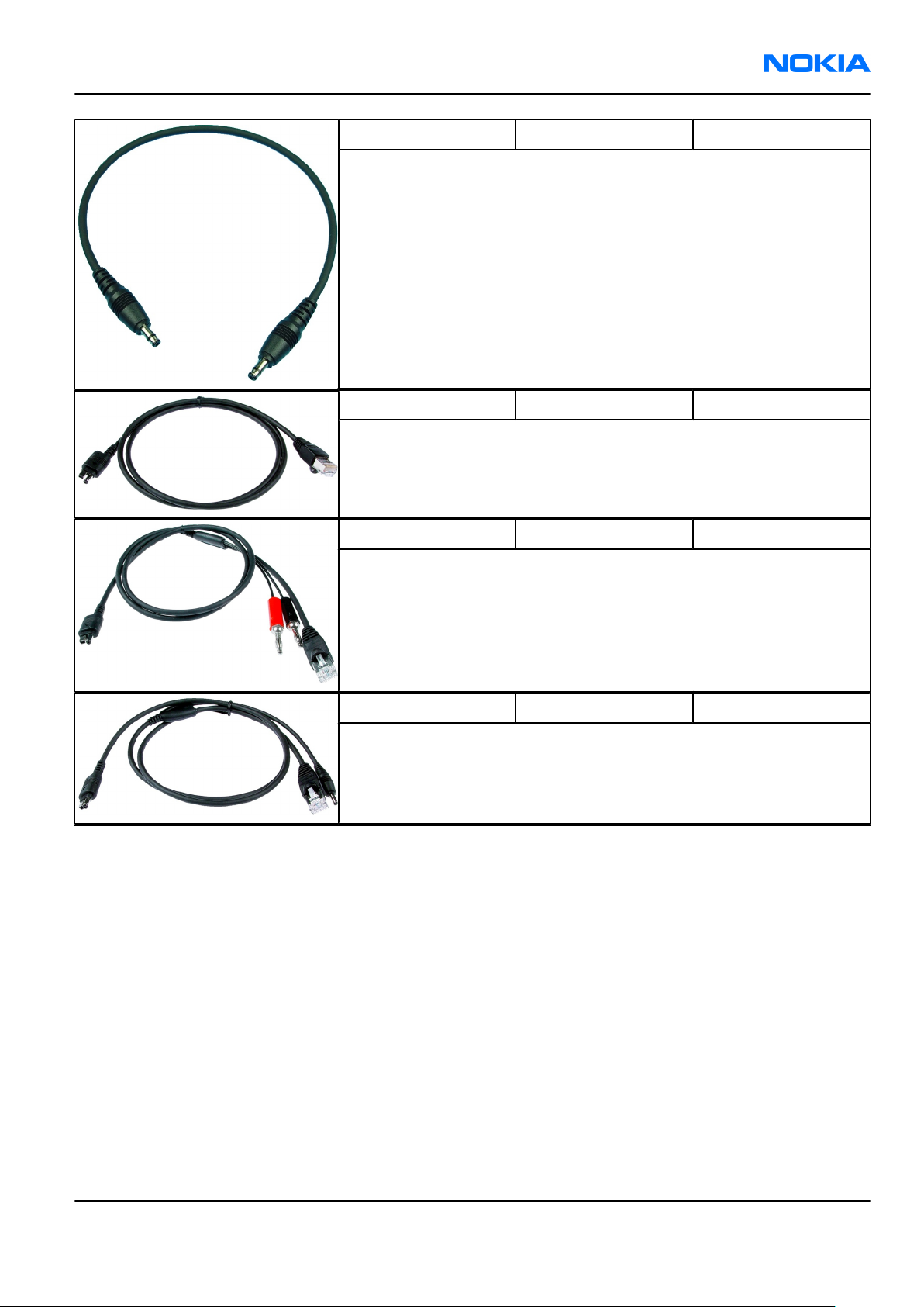
RM-111
Service tools and concepts Nokia Customer Care
CA-5S DC cable The DC cable CA-5S is used to connect JBV-1 to the phone charger jack
for ADC/VCHAR/ICHAR calibration
Note: Old SCB-3 can be used as well.
CA-65DS DS easy flash cable The CA-65 DS easy flash cable is used to connect the phone bottom
connector to either POS flashing device (FLS-4S) or to the PROMMER
box (FPS-11).
CA-66DS Easy flash cable This cable connects the phone DC port to the FPS-8 prommer.
CA-67DS Easy flash cable This cable connects the phone DC port to the FPS-10 prommer.
Issue 1 COMPANY CONFIDENTIAL Page 4 –7
Copyright © 2005 Nokia. All rights reserved.
Page 82

RM-111
Nokia Customer Care Service tools and concepts
DA-60 Docking station
adapter
The Docking Station adaptor is used for this phone in combination
with JBV-1 and antenna coupler SA-41. The adapter supports flashing
with CA-65/66/67 and RF testing with SA-41.
Features include:
• compatible with the JBV-1 (only mechanically!)
• easy phone attachment and detachment.
• reliable phone locking
Note: DA-60 has no electrical functionality. Connection is
only possible by using one of the data cables CA-65DS,
CA-66DS or CA67DS.
Note: Energy calibration is not possible as there is no access
to the battery contacts!
RF loss when using the SA-41 is the following:
• GSM900: 5 ± 1 dB
• GSM1800: 5 ± 1 dB
• GSM1900: 9 ± 1 dB
DAU-9S MBUS cable
The MBUS cable DAU-9S has a modular connector and is used, for
example, between the PC's serial port and module jigs, flash adapters
or docking station adapters.
Note: Docking station adapters valid for DCT4 products.
FLC-2 DC cable FLC-2 is used with a flash adapter to supply a controlled operating
voltage.
Page 4 –8 COMPANY CONFIDENTIAL Issue 1
Copyright © 2005 Nokia. All rights reserved.
Page 83

RM-111
Service tools and concepts Nokia Customer Care
FLS-4S Flash device FLS-4S is a dongle and flash device incorporated into one package,
developed specifically for POS use.
FPS-10 Flash prommer FPS-10 interfaces with:
• PC
• Control unit
• Flash adapter
• Smart card
FPS-10 flash prommer features:
• Flash functionality for BB5 and DCT-4 terminals
• Smart Card reader for SX-2 or SX-4
• USB traffic forwarding
• USB to FBUS/Flashbus conversion
• LAN to FBUS/Flashbus and USB conversion
• Vusb output switchable by PC command
FPS-10 sales package includes:
• FPS-10 prommer
• Power Supply with 5 country specific cords
• USB cable
JBV-1 Docking station
The JBV-1 docking station is a general tool that has been designed for
calibration and software update use. The JBV-1 is used together with
a docking station adapter as one unit
In calibration mode the JBV-1 is powered by an external power supply:
11-16V DC. When flashing the power for the phone must be taken from
the flash prommer.
Note: JBV-1 main electrical functions are:
• adjustable VBATT calibration voltage, current
measurement limit voltage: VCHAR, current measurement:
ICHAR
• adjustable ADC calibration voltage via BTEM and the BSI
signal
• BTEMP and BSI calibration resistor
• signal from FBUS to the phone via the parallel jig
• control via FBUS or USB
• Flash OK/FAIL indication
Issue 1 COMPANY CONFIDENTIAL Page 4 –9
Copyright © 2005 Nokia. All rights reserved.
Page 84

RM-111
Nokia Customer Care Service tools and concepts
MJ-84 Module jig The MJ-84 module jig is used for testing the following modules:
• User interface
• Baseband and RF on system module
Note: The nominal supply voltage for MJ-84 is +6.0 V. The
supply voltage must not exceed +12.0 V (min. 5.0 V).
Supply the power to the jig only when the jumper is open =
regulated.
RF loss in MJ-84:
• GSM900: 0.4 dB
• GSM1800: 0.8 dB
• GSM1900: 0.8 dB
• Bluetooth: 1.8 dB
Note: The MJ-84 is backward compatible with RM-14, Nokia
7280. To use it for RM-14, replace the connection PWB and
turn the two black support parts 180 degrees.
PCS-1 Power cable The PCS-1 power cable (DC) is used with a docking station, a module
jig or a control unit to supply a controlled operating voltage.
PKD-1 SW security device SW security device is a piece of hardware enabling the use of the
service software when connected to the parallel (LPT) port of the PC.
Without the device, it is not possible to use the service software.
Printer or any such device can be connected to the PC through the
device if needed.
RJ-97 Soldering jig The soldering jig RJ-97 is used for soldering and as a rework jig for the
main board. The material is resistant to the heat used by lead free
soldering.
The PWB can be used with either A or B side upwards.
Page 4 –10 COMPANY CONFIDENTIAL Issue 1
Copyright © 2005 Nokia. All rights reserved.
Page 85

RM-111
Service tools and concepts Nokia Customer Care
SA-41 RF Coupler SA-41 RF Coupler is used for Go/No-Go test after changing components
in the RF part of the phone.
The SA-41 is mounted on the docking station adapter.
Note: For RF attenuation values, please refer to the Service
bulletin.
SRT-6 Opening tool
SS-45 Front camera
removal tool
The front camera removal tool SS-45 is used to remove/attach the
front camera module from/to the socket.
SX-4 Smart card SX-4 is a BB5 security device used to protect critical features in tuning
and testing.
SX-4 is also needed together with FPS-10 when DCT-4 phones are
flashed.
Issue 1 COMPANY CONFIDENTIAL Page 4 –11
Copyright © 2005 Nokia. All rights reserved.
Page 86

RM-111
Nokia Customer Care Service tools and concepts
XCS-1 Service cable The XCS-1 service cable is used to connect FLS-4S to the POS flash
adapter for supplying a controlled operating voltage and data
connection.
XCS-4 Modular cable XCS-4 is a shielded (one specially shielded conductor) modular cable
for flashing and service purposes.
XRF-1 RF cable The RF cable is used to connect, for example, a module repair jig to
the RF measurement equipment.
SMA to N-Connector ca. 610mm.
Attenuation for:
• GSM850/900: 0.3+-0.1 dB
• GSM1800/1900: 0.5+-0.1 dB
• WLAN: 0.6+-0.1dB
Page 4 –12 COMPANY CONFIDENTIAL Issue 1
Copyright © 2005 Nokia. All rights reserved.
Page 87

RM-111
Service tools and concepts Nokia Customer Care
Service concepts
Service concepts for RM-111
Go/Nogo test
Figure 71 Service concept: Go/Nogo test
Issue 1 COMPANY CONFIDENTIAL Page 4 –13
Copyright © 2005 Nokia. All rights reserved.
Page 88

RM-111
Nokia Customer Care Service tools and concepts
Easy Flash concept
Figure 72 Service concept: Easy Flash
Page 4 –14 COMPANY CONFIDENTIAL Issue 1
Copyright © 2005 Nokia. All rights reserved.
Page 89

RM-111
Service tools and concepts Nokia Customer Care
POS flash with FPS-8
Figure 73 Service concept: POS flash with FPS-8
Issue 1 COMPANY CONFIDENTIAL Page 4 –15
Copyright © 2005 Nokia. All rights reserved.
Page 90

RM-111
Nokia Customer Care Service tools and concepts
POS flash with FPS-10
Figure 74 Service concept: POS flash with FPS-10
Page 4 –16 COMPANY CONFIDENTIAL Issue 1
Copyright © 2005 Nokia. All rights reserved.
Page 91

RM-111
Service tools and concepts Nokia Customer Care
Module jig concept with FPS-8 flash prommer
Figure 75 Service concept: Module jig concept with FPS-8 flash prommer
Issue 1 COMPANY CONFIDENTIAL Page 4 –17
Copyright © 2005 Nokia. All rights reserved.
Page 92

RM-111
Nokia Customer Care Service tools and concepts
Module jig concept with FPS-10 flash prommer
Figure 76 Service concept: Module jig concept with FPS-10 flash prommer
Page 4 –18 COMPANY CONFIDENTIAL Issue 1
Copyright © 2005 Nokia. All rights reserved.
Page 93

RM-111
Service tools and concepts Nokia Customer Care
Module jig service concept
Figure 77 Service concept: Module jig service concept
Issue 1 COMPANY CONFIDENTIAL Page 4 –19
Copyright © 2005 Nokia. All rights reserved.
Page 94

RM-111
Nokia Customer Care Service tools and concepts
(This page left intentionally blank.)
Page 4 –20 COMPANY CONFIDENTIAL Issue 1
Copyright © 2005 Nokia. All rights reserved.
Page 95

Nokia Customer Care
5 — Disassembly and
reassembly instructions
Issue 1 COMPANY CONFIDENTIAL Page 5 –1
Copyright © 2005 Nokia. All rights reserved.
Page 96

RM-111
Nokia Customer Care Disassembly and reassembly instructions
(This page left intentionally blank.)
Page 5 –2 COMPANY CONFIDENTIAL Issue 1
Copyright © 2005 Nokia. All rights reserved.
Page 97

RM-111
Disassembly and reassembly instructions Nokia Customer Care
Table of Contents
Disassembly instructions.......................................................................................................................................5–5
Reassembly instructions......................................................................................................................................5–11
Issue 1 COMPANY CONFIDENTIAL Page 5 –3
Copyright © 2005 Nokia. All rights reserved.
Page 98

RM-111
Nokia Customer Care Disassembly and reassembly instructions
(This page left intentionally blank.)
Page 5 –4 COMPANY CONFIDENTIAL Issue 1
Copyright © 2005 Nokia. All rights reserved.
Page 99

RM-111
Disassembly and reassembly instructions Nokia Customer Care
Disassembly instructions
Steps
1. You need the following tools.
2. Open the clips of the B-cover. Starting at the bottom side. Slide the SRT-6 to the top carefully.
3. Continue on the other side...
4. ...and the top side.
Issue 1 COMPANY CONFIDENTIAL Page 5 –5
Copyright © 2005 Nokia. All rights reserved.
Page 100

RM-111
Nokia Customer Care Disassembly and reassembly instructions
5. Remove the B-cover.
Note: Always use a new B-cover when reassembling the unit.
6. Use the SRT-6 to lift the light guide and unlock the shown side of the A-cover assy.
7. Slide the SRT-6 along the A-cover to lift it a bit.
8. Remove the A-cover. Be careful not to damage the flex foil of the UI module.
Note: Always use a new A-cover when reassembling the unit.
Page 5 –6 COMPANY CONFIDENTIAL Issue 1
Copyright © 2005 Nokia. All rights reserved.
 Loading...