

Page 1

Nokia Customer Care
3 - Service Sof tware and
Tuning Instructions
Issue 1 11/2005 COMPANY CONFIDENTIAL
Copyright © 2005 Nokia. All Rights Reserved.
Page 2

Nokia Customer Care
Technical type
[This page intentionally blank]
2 COMPANY CONFIDENTIAL Issue 1 11/2005
Copyright © 2005 Nokia. All Rights Reserved.
Page 3

RM-127
3 - Service Software and Tuning Instructions Nokia Customer Care
Table of Contents
Page No
Quick Guide for Phoenix Service SW Installation............................................ 5
Phoenix Installation Steps in Brief....................................................................6
Phoenix Service SW............................................................................................7
Before installation............................................................................................... 7
Installing Phoenix............................................................................................... 8
Updating Phoenix installation........................................................................... 12
Uninstalling Phoenix......................................................................................... 13
Repair............................................................................................................... 15
Data Package for Phoenix (Product Specific) ................................................ 17
Before installation............................................................................................. 17
Installing Phoenix data package (product specific).......................................... 17
Uninstalling the data package.......................................................................... 21
Configuring Users............................................................................................. 22
Managing Connections..................................................................................... 24
Updating Flash Support Files for FPS-8* and FLS-4*.................................... 27
Before installation ............................................................................................ 27
Installing the flash support files (only separate installation package) .............. 27
Updating FPS-8* flash prommer SW ............................................................... 30
Activating and Deactivating FPS-8.................................................................. 33
Activating FPS-8.............................................................................................. 33
Deactivating FPS-8.......................................................................................... 34
JBV-1 Docking Station SW............................................................................... 35
Before installation ............................................................................................ 35
Installing SW needed for the JBV-1 SW update.............................................. 35
Baseband Calibration ....................................................................................... 41
General instructions for tuning......................................................................... 41
UEMEK calibration........................................................................................... 41
Calibration limits .............................................................................................42
Phoenix Tuning ................................................................................................ 43
General instructions for tuning......................................................................... 43
RF tuning after repairs..................................................................................... 43
Semi-automatic calibrations and measurements - step by step: RX/TX and GSM
bands ................................................................................................................. 45
RX channel select filter calibration .................................................................45
RX calibration GSM900, GSM1800 and GSM1900 .......................................46
Issue 1 11/2005 COMPANY CONFIDENTIAL 3
Copyright © 2005 Nokia. All Rights Reserved.
Page 4

RM-127
Nokia Customer Care 3 - Service Software and Tuning Instructions
RX band filter response compensation .......................................................... 49
TX power level tuning ....................................................................................53
TX I/Q tuning ..................................................................................................59
Fully automatic calibration, tuning & measurement by Phoenix <Auto-Tune> 64
Preparations for Phoenix ...............................................................................65
Automatic tuning procedure ........................................................................... 67
4 COMPANY CONFIDENTIAL Issue 1 11/2005
Copyright © 2005 Nokia. All Rights Reserved.
Page 5
RM-127
3 - Service Software and Tuning Instructions Nokia Customer Care
Quick Guide for Phoenix Service SW Installation
Issue 1 11/2005 COMPANY CONFIDENTIAL 5
Copyright © 2005 Nokia. All Rights Reserved.
Page 6

RM-127
Nokia Customer Care 3 - Service Software and Tuning Instructions
Phoenix Installation Steps in Brief
DCT-4 generation Test and Service Software is called “Phoenix”.
These are the basic steps to install Phoenix:
• Connect a DK2 dongle or FLS-4S POS flash device.
• Install the Phoenix Service SW.
• Install the data package for Phoenix.
• Configure users.
• Manage connection settings (depends on the tools you are using).
Phoenix is now ready for FLS-4S Point Of Sales Flash Device use.
If you use FPS-8 (support for FPS-8 will be finished to the end of RM-127 lifetime):
• Update FPS-8 SW.
• Activate FPS-8.
• Update JBV-1 docking station SW (only when needed).
Phoenix is now ready to be used also with FPS-8 flash prommer and other tools.
The Phoenix Service Software installation contains:
• service software support for all phone models included in the package
• flash update package files for FPS-8* and FLS-4S programming devices
• all needed drivers for:
- DK2 dongle
- FLS-4S point of sales flash device
- USB devices
Separate installation packages for flash update file s and drivers are also available, but it is not
necessary to use them unless updates appear between Phoenix Service SW releases. If separate update packages are used, they should be used after Phoenix and data packages have
been installed.
The phone model specific data package includes all changing product specific data:
• product software Binary files
• files for type label printing
• validation file for the Faultlog repair data reporting system
• all product specific configuration files for Phoenix software components
Please refer to Service Manual and Technical Bulletins for more information concerning phone
model specific service tools and equipment setup.
Phoenix Service SW and phone data packages should only be used as complete installation
packages. Uninstallation should be made from Windows Control Panel.
6 COMPANY CONFIDENTIAL Issue 1 11/2005
Copyright © 2005 Nokia. All Rights Reserved.
Page 7
RM-127
3 - Service Software and Tuning Instructions Nokia Customer Care
Phoenix Service SW
■ Before installation
• Check that a dongle is attached to the parallel port of your computer .
• Download the installation package (e.g.
phoenix_service_sw_a_2005_35_1_184.exe) to your computer (e.g. C:\TEMP).
• Close all other programs.
• Run the application file (e.g. phoenix_service_sw_a_2005_35_1_184.exe) and
follow instructions on the screen.
Administrator rights may be required to be able to in st all Phoenix depen ding on the Opera ting
System
If uninstalling or rebooting is needed at any point, you will be prompted by the Inst all Shield program.
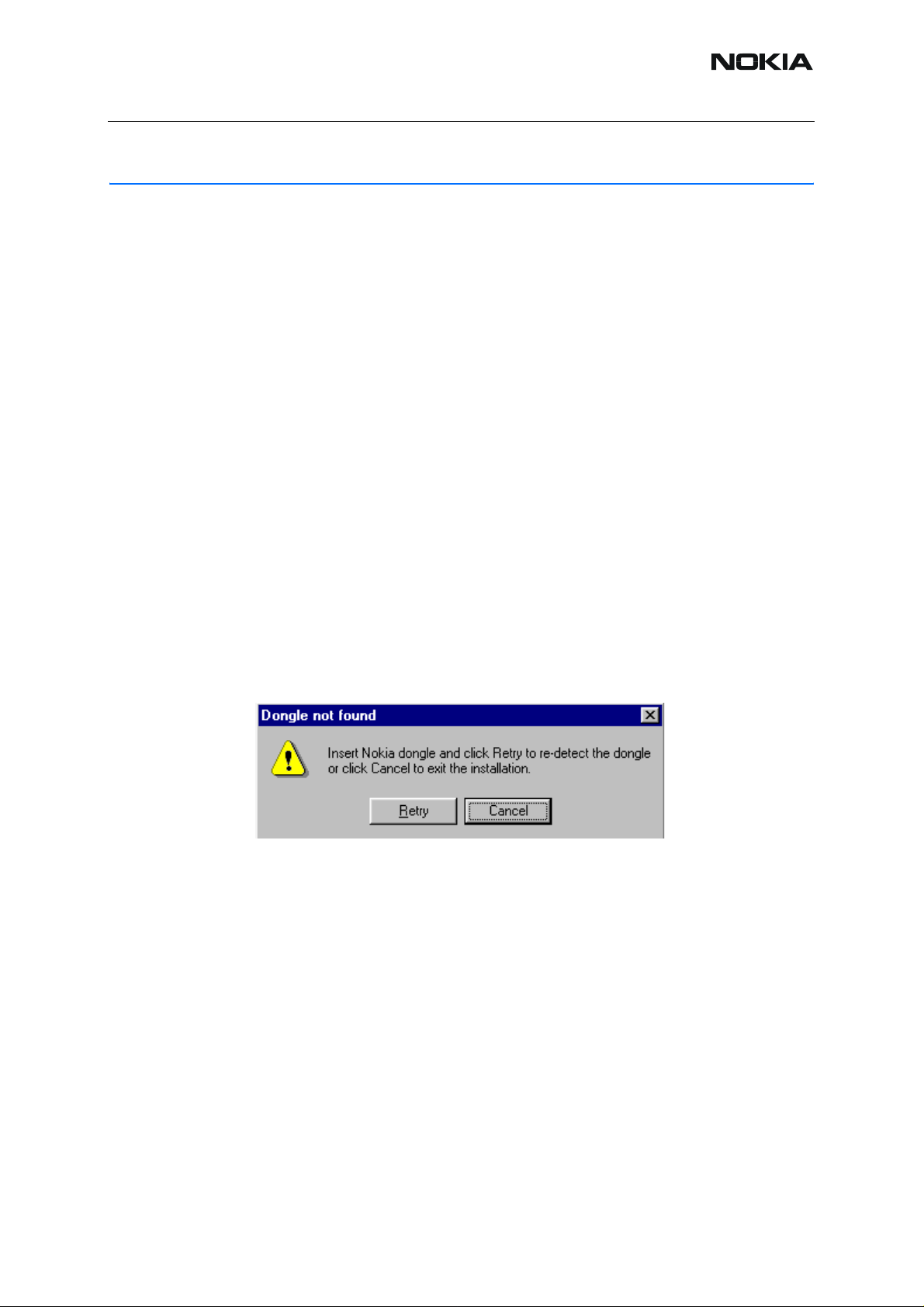
If at any point during installation you get this message, the dongle is not fo und and inst allation
cannot continue.
Possible reasons may be defective or too old PKD-1Dongle (five digit serial number dongle
when used with FPS-8 Prommer) or that the FLS-4S POS Flash Dongle is defective or power
to it is not supplied by external charger.
First, check the COM /parallel ports used! Af ter correcting the proble m, the inst allatio n can be
restarted.
Issue 1 11/2005 COMPANY CONFIDENTIAL 7
Copyright © 2005 Nokia. All Rights Reserved.
Page 8
RM-127
Nokia Customer Care 3 - Service Software and Tuning Instructions
■ Installing Phoenix
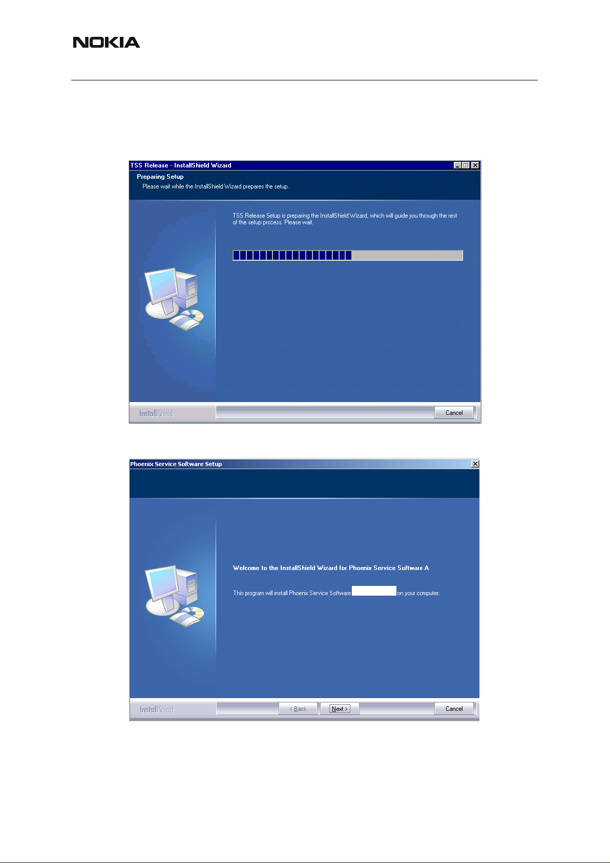
Run the phoenix_service_sw_a_2005_35_1_184.exe to start the inst allation. Install Shield will
prepare.
To continue, click "Next" in the Welcome dialog.
A 2005.35.1.184
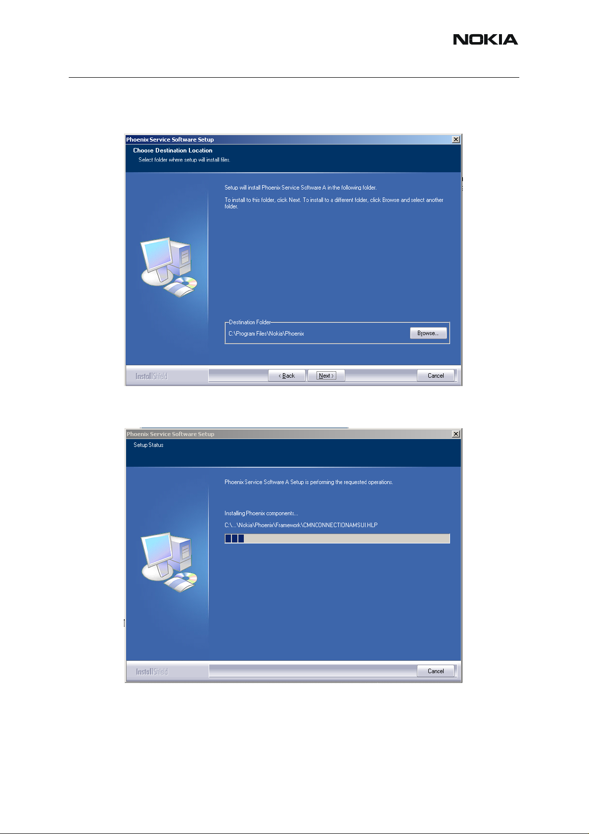
Choose the destination folder, it is recommended to use the default folder C:\Program-
Files\Nokia\Phoenix.
8 COMPANY CONFIDENTIAL Issue 1 11/2005
Copyright © 2005 Nokia. All Rights Reserved.
Page 9
RM-127
3 - Service Software and Tuning Instructions Nokia Customer Care
Choose “Next” to continue. You may choose another location by selecting “Browse” (not recommended).
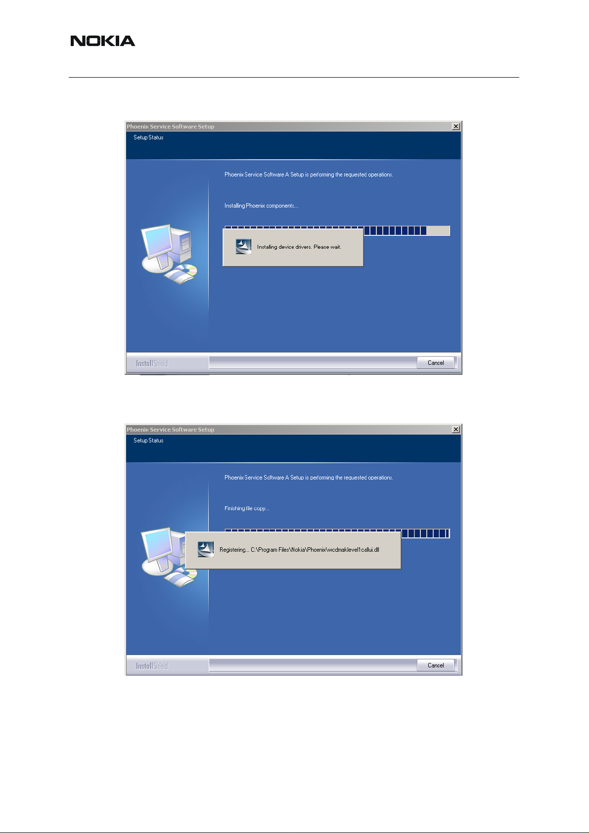
Setup copies the components, progress of the setup is shown. Please wait.
Drivers are installed and updated, please wait. The process may t ake several minutes to complete.
Issue 1 11/2005 COMPANY CONFIDENTIAL 9
Copyright © 2005 Nokia. All Rights Reserved.
Page 10
RM-127
Nokia Customer Care 3 - Service Software and Tuning Instructions
If the operating system does not require rebooting (Win2000, XP), the PC compone nts are
registered straight away.
10 COMPANY CONFIDENTIAL Issue 1 11/2005
Copyright © 2005 Nokia. All Rights Reserved.
Page 11
RM-127
3 - Service Software and Tuning Instructions Nokia Customer Care
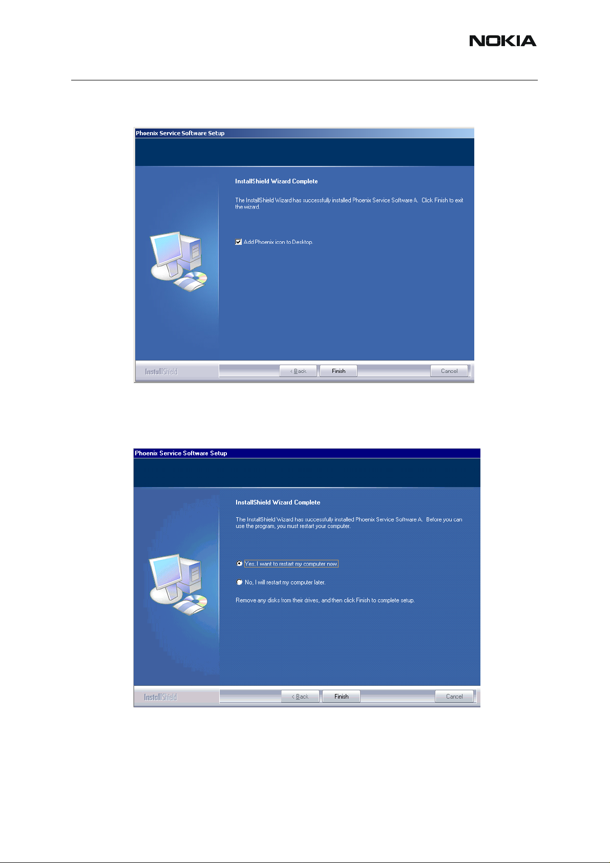
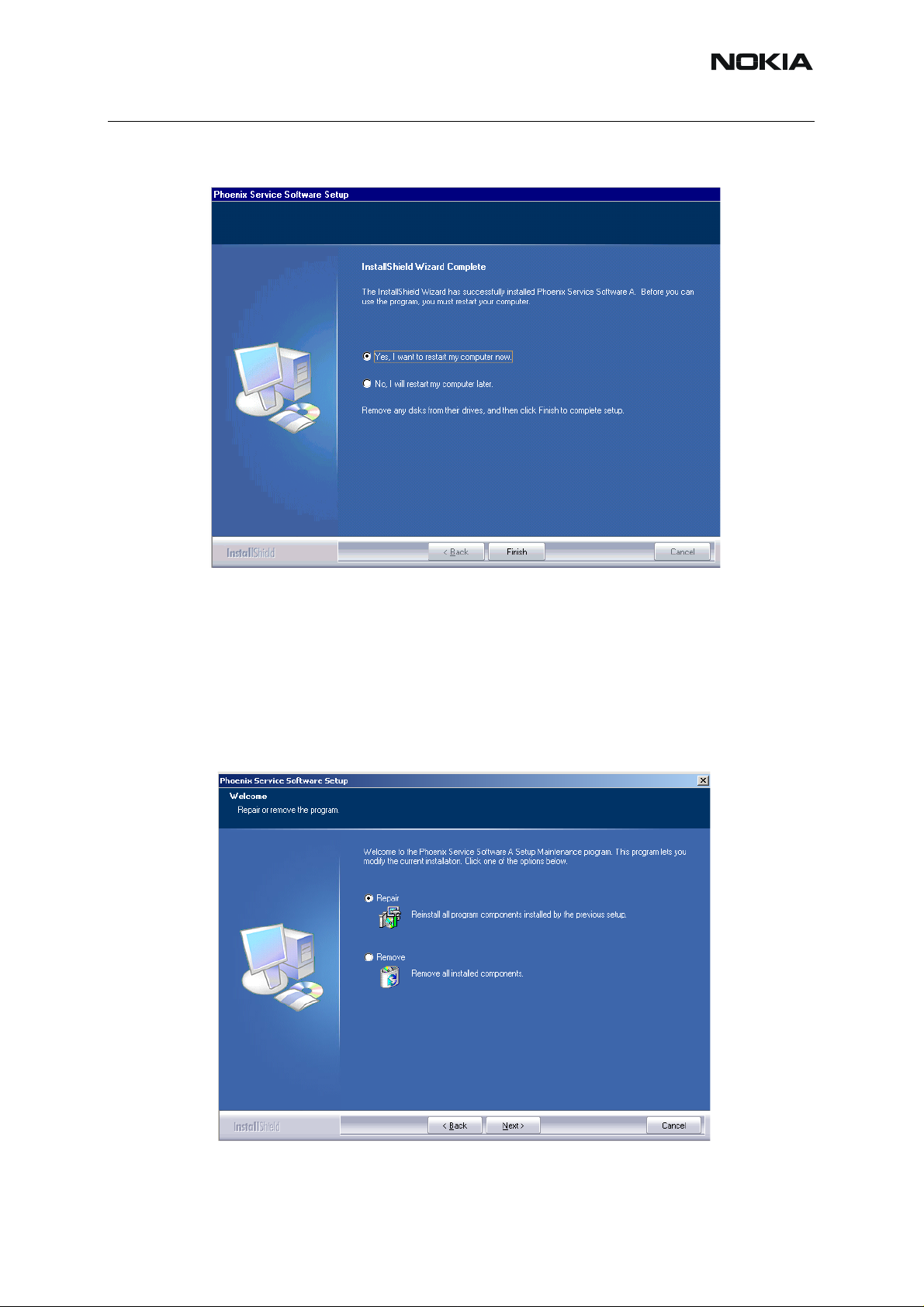
Click "Finish" to finalize. Phoenix is ready for use.
If the operating system used requires restarting your computer (Win2000 or XP), the Install Shield Wizard notifies you about it. Select "Y es..." to reboot the PC immediately and "No..."
to reboot the PC manually afterwards.
After the reboot components are registered and Phoenix is ready for use. Note that Phoenix
doesn't work, if components are not registered.
Issue 1 11/2005 COMPANY CONFIDENTIAL 11
Copyright © 2005 Nokia. All Rights Reserved.
Page 12

RM-127
Nokia Customer Care 3 - Service Software and Tuning Instructions
Now the installation of Phoenix Service SW is ready and it can be used after:
• installing phone model specific Phone Data Package for Phoenix
• configuring users and connections
FLS-4S can be used right away.
FPS-8* can be used after updating Flash Update Package files to it .
■ Updating Phoenix installation
If you already have the Phoenix Service SW installed on your computer, sooner or later there
will be need to update it when new versions are released.
Always use the latest available versions of both the Phoenix Service SW and the phone specific
data package. Instructions can be found in phone model specific Technical Bulletins and phone
data package readme.txt files (shown during installation).
To update Phoenix, you need to take exactly the same steps as when installing it for the first
time.
• Download the installation package to your computer hard disk.
• Close all other programs.
• Run the application file (e.g. phoenix_service_sw_a_2005_35_1_184.exe).
A newer version of Phoenix will be installed.
Driver versions will be checked and if need be, updated.
When you update Phoenix from an old to a new version (e.g. a11_2003_41_5_28 to
a_2005_35_1_184 ), the update will take place automatically without uninst alla tion.
If you try to update Phoenix with the same version that you already have (e.g.
a_2005_35_1_184 to a_2005_35_1_184), you are asked if you want to uninstall the version
of Phoenix you have on your PC. In this case, you can choose between total uninstallation and
repair, just like when you choose to uninstall Phoenix service softwa re from the W indo ws co ntrol panel.
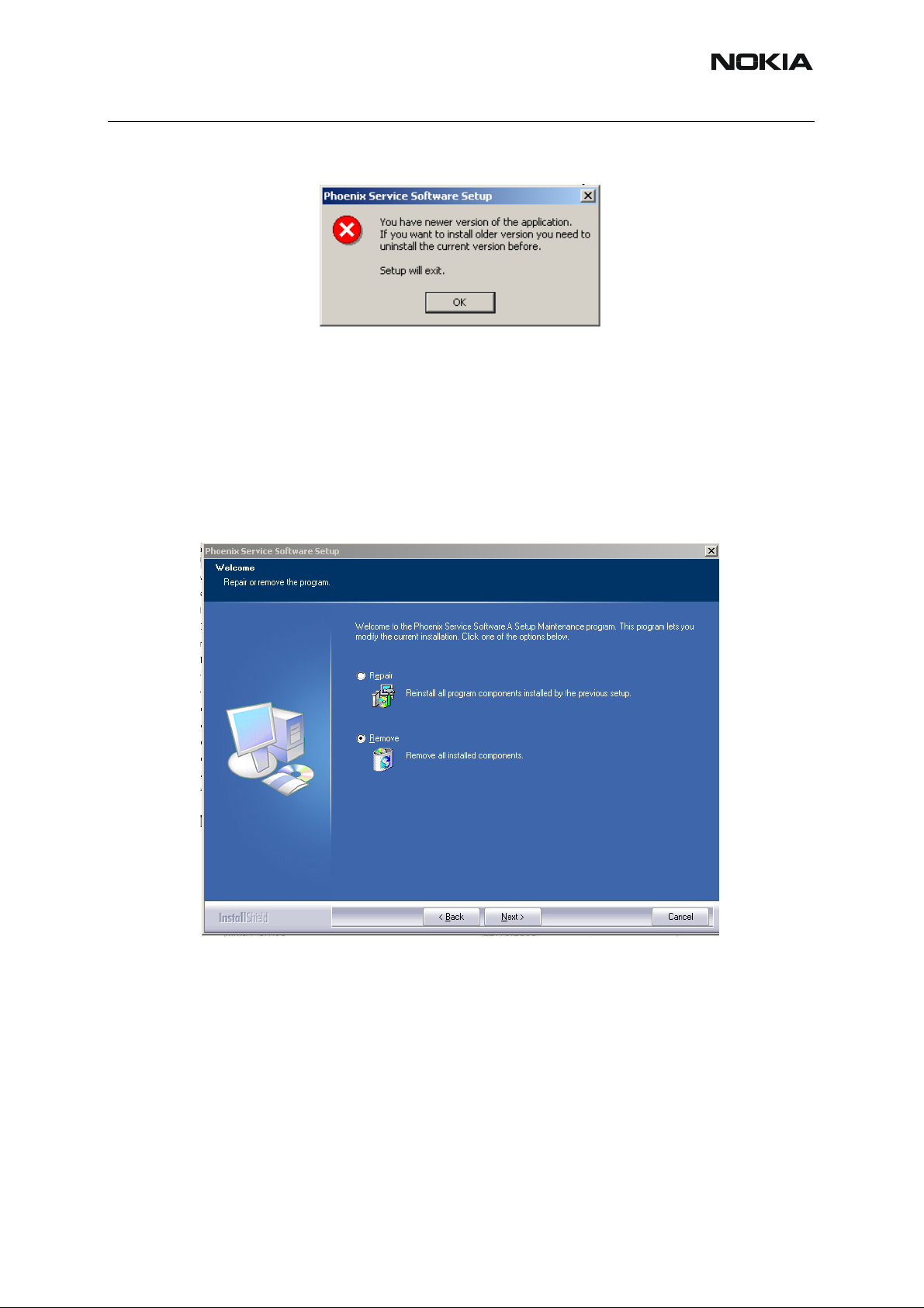
If you try to install an older version (e.g. downgrade from a_2005_35_1_184 to
a11_2003_41_5_28) the installation will be interrupted.
12 COMPANY CONFIDENTIAL Issue 1 11/2005
Copyright © 2005 Nokia. All Rights Reserved.
Page 13
RM-127
3 - Service Software and Tuning Instructions Nokia Customer Care
Please always follow the instructions on the screen.
■ Uninstalling Phoenix
Uninstallation can be done manually from Wind ows Con trol Panel - Add / Remove Programs.
Choose “Phoenix Service Software” and click "Add/Remove".
Choose “Remove” to uninstall Phoenix.
Issue 1 11/2005 COMPANY CONFIDENTIAL 13
Copyright © 2005 Nokia. All Rights Reserved.
Page 14
RM-127
Nokia Customer Care 3 - Service Software and Tuning Instructions
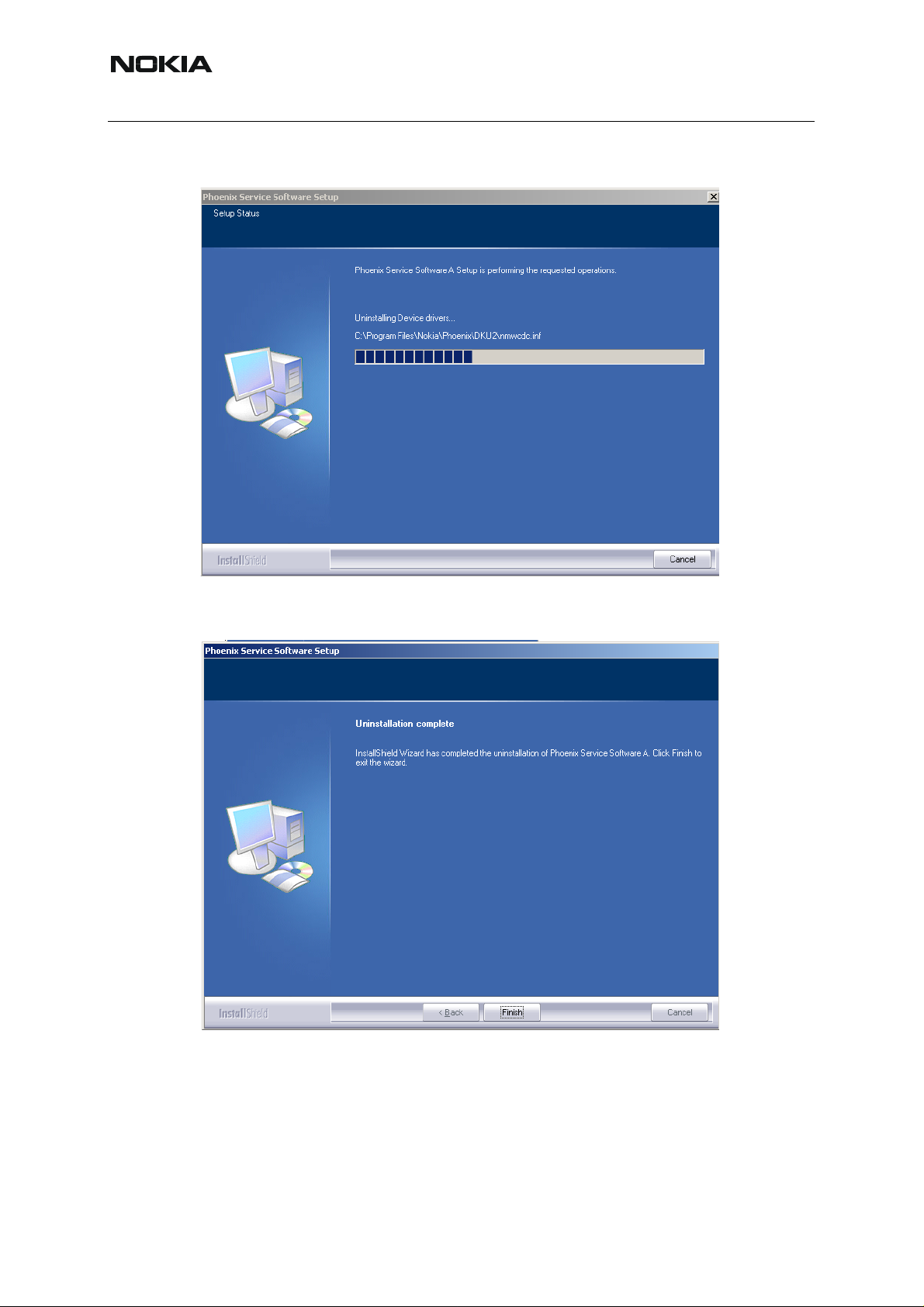
Progress of the uninstallation is shown.
If the operating system does not require rebooting, select “Finish” to complete.
If the operating system requires rebooting, Install Shield Wizard notifies you about it. Select
"Yes..." to reboot the PC immediately and "No..." to reboot the PC manually afterwards.
14 COMPANY CONFIDENTIAL Issue 1 11/2005
Copyright © 2005 Nokia. All Rights Reserved.
Page 15
RM-127
3 - Service Software and Tuning Instructions Nokia Customer Care
■ Repair
If you experience any problems with the service software or suspect that files have been lost,
you can use the repair function before completely reinstalling Phoenix. Note that the original
installation package (e.g. phoenix_service_sw_a_2005_35_1_184.exe) must be found on
your PC when you run the repair setup.
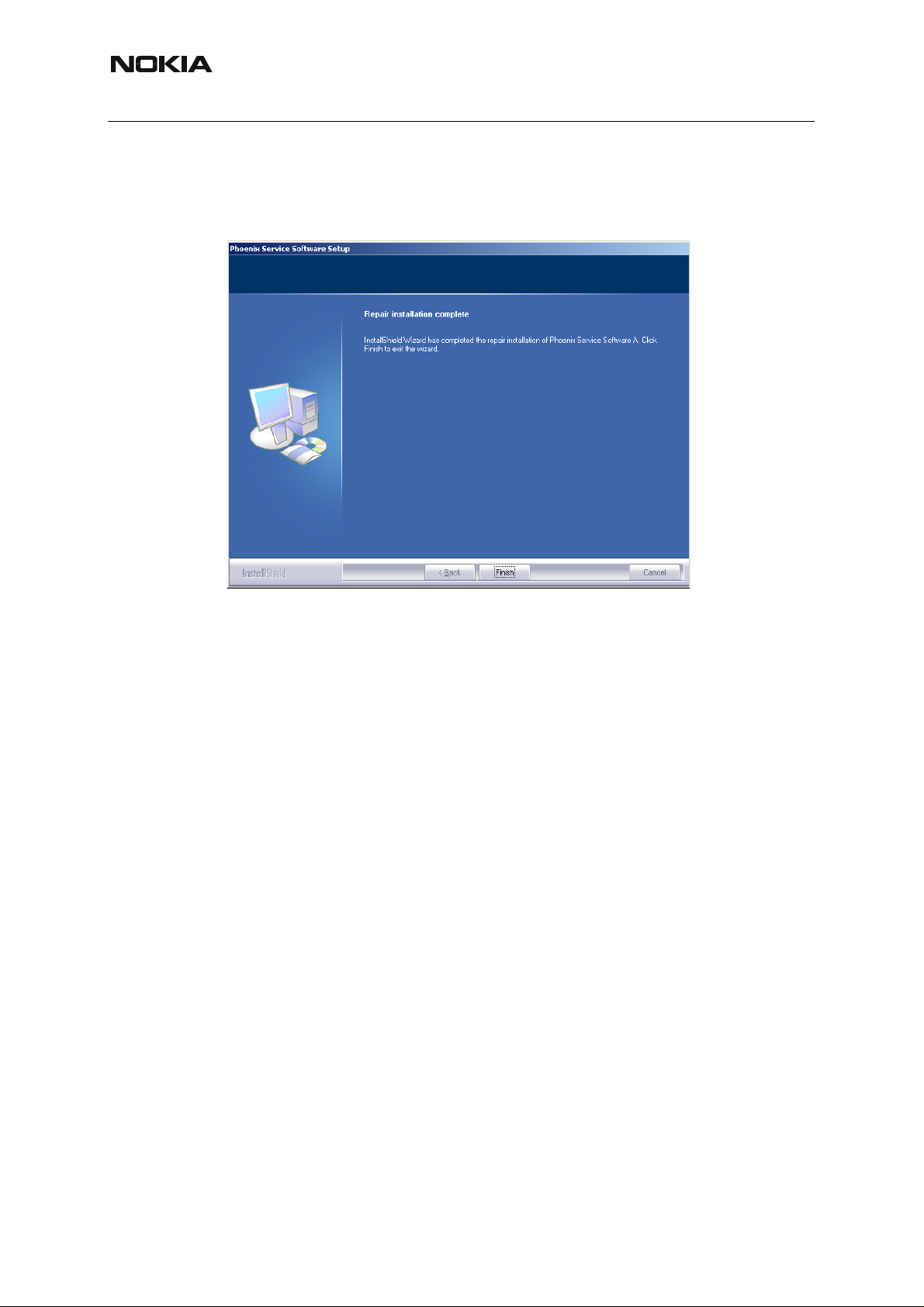
Run Windows Control Panel - Add / Remove Programs, choose “Phoenix Service Software”.
Click "Add/Remove". In the following view, choose “Repair”.
Issue 1 11/2005 COMPANY CONFIDENTIAL 15
Copyright © 2005 Nokia. All Rights Reserved.
Page 16
RM-127
Nokia Customer Care 3 - Service Software and Tuning Instructions
Phoenix reinstalls the required components and registers them, the proce dure is the same as
in the update installation.
To complete, choose “Finish” .
16 COMPANY CONFIDENTIAL Issue 1 11/2005
Copyright © 2005 Nokia. All Rights Reserved.
Page 17
RM-127
3 - Service Software and Tuning Instructions Nokia Customer Care
Data Package for Phoenix (Product Specific)
■ Before installation
Product Data Package contains all product specific data to make the Phoenix Service Sof tware
and tools usable with a certain phone model.
• Check that the dongle is attached to the parallel port of your computer.
• Install Phoenix Service SW.
• Download the installation package (e.g. RM-127_dp_v_0.00_mcuA0.00.0.exe)
to your computer (e.g. C:\TEMP)
• Close all other programs.
• Run the application file (e.g. RM-127_dp_v_0.00_mcuA0.00.0.exe ) and follow
the instructions on the screen.
Please note that very often the Phoenix Service SW and t he Phone Specific Data Package fo r
Phoenix come in pairs, meaning that certain version of Phoenix can only be used with certain
version of the data package. Always use the latest available versions of both. Instructions ca n
be found in phone model specific Technical Bulletins and readme.txt files of the data packages.
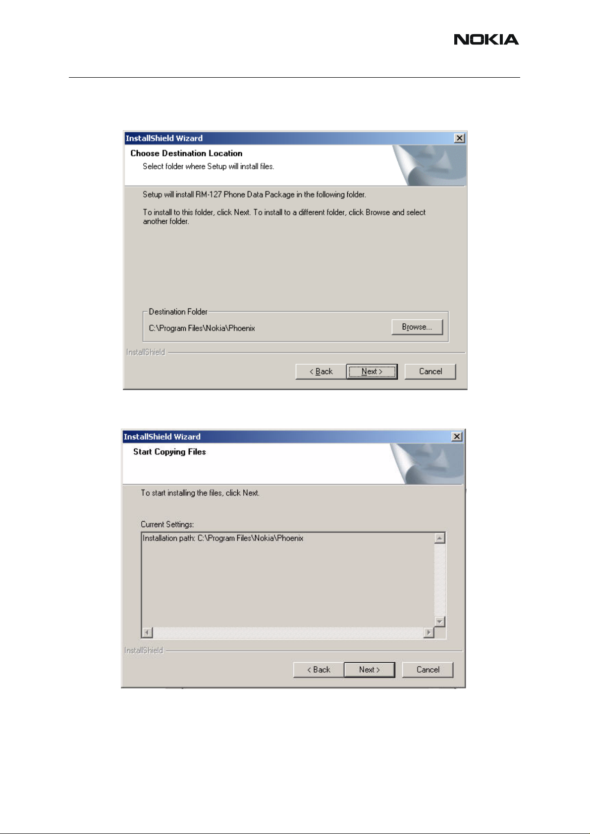
■ Installing Phoenix dat a package (product specific)
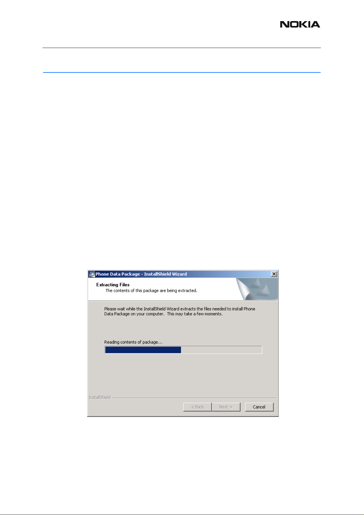
Run the RM-127_dp_v_0.00_mcuA0.00.0.exe to start installation.
Choose “Next”. The files needed for installation will be extracted. Please wait.
Issue 1 11/2005 COMPANY CONFIDENTIAL 17
Copyright © 2005 Nokia. All Rights Reserved.
Page 18
RM-127
Nokia Customer Care 3 - Service Software and Tuning Instructions
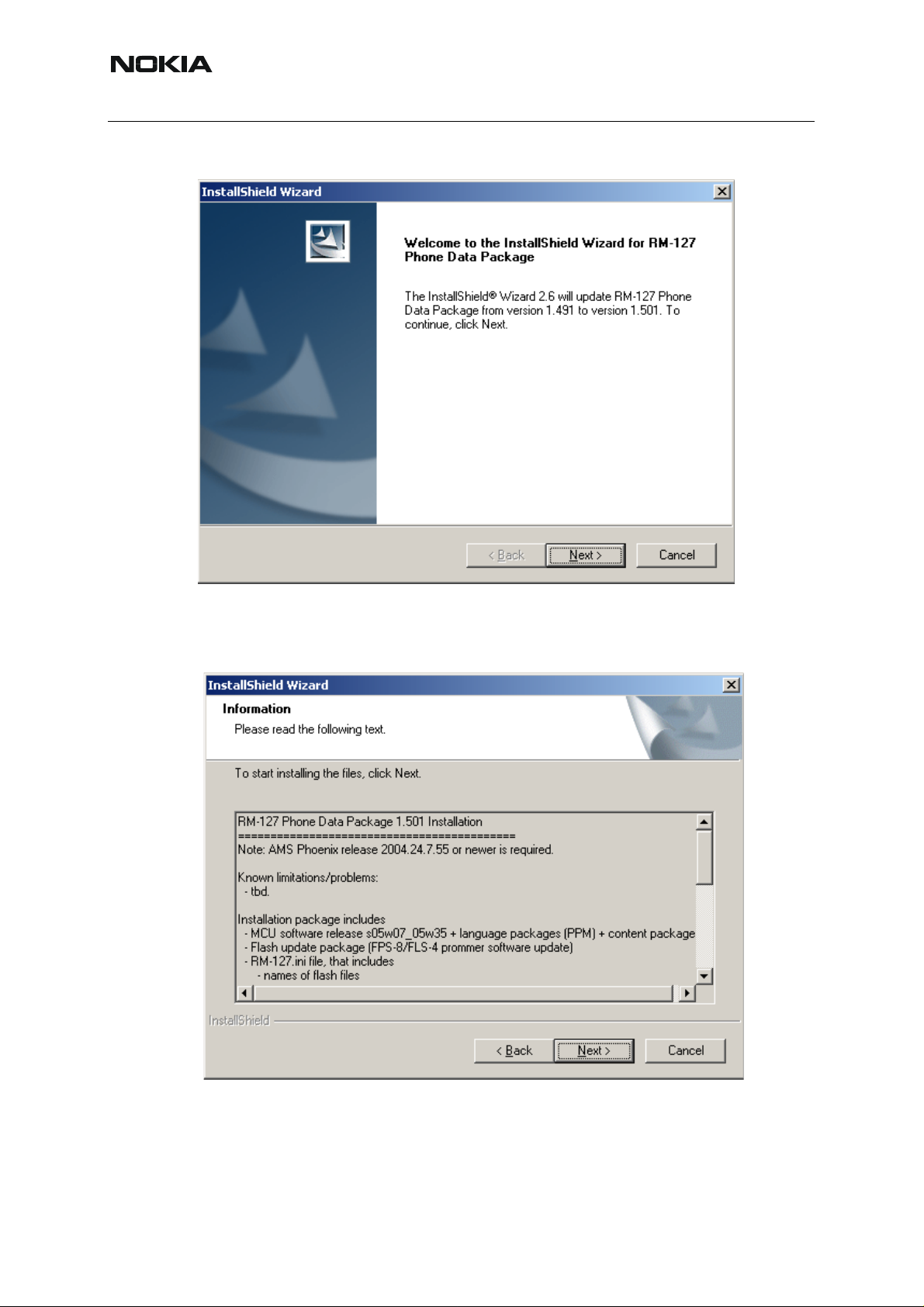
To continue, choose “Next”.
In this view, you can see the contents of the data package. Read the text carefully. There
should be information about the Phoenix version needed with this data package. Choose
“Next”.
18 COMPANY CONFIDENTIAL Issue 1 11/2005
Copyright © 2005 Nokia. All Rights Reserved.
Page 19
RM-127
3 - Service Software and Tuning Instructions Nokia Customer Care
To continue, confirm the location and choose “Next” . Install shield checks where the Phoenix
application is installed and the directory is shown. Choose “Next” to continue.
To start copying the files, choose “Next”.
Issue 1 11/2005 COMPANY CONFIDENTIAL 19
Copyright © 2005 Nokia. All Rights Reserved.
Page 20
RM-127
Nokia Customer Care 3 - Service Software and Tuning Instructions
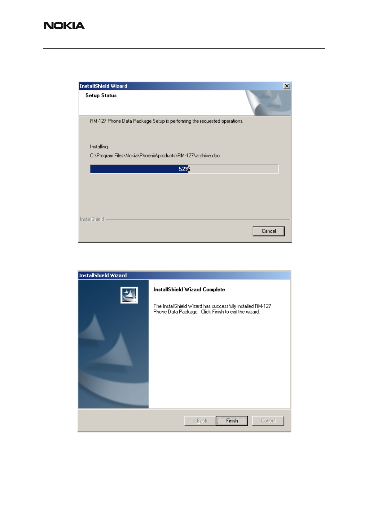
Phone model specific files are installed. Please wait.
To complete installation, choose “Finish”.
You now have all phone model specific files installed in your Phoenix service SW.
Now Phoenix can be used to for example flash phones and print type labels after:
20 COMPANY CONFIDENTIAL Issue 1 11/2005
Copyright © 2005 Nokia. All Rights Reserved.
Page 21
RM-127
3 - Service Software and Tuning Instructions Nokia Customer Care
• configuring users
• managing connections
FLS-4S can be used right away.
FPS-8* can be used after updating flash update package files to it .
■ Uninstalling the data package
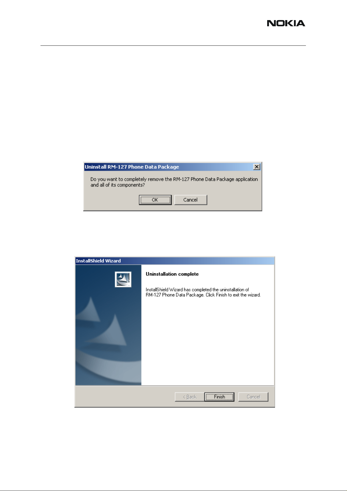
Uninstallation can also be done manually from Windows Control Panel / Add / Remove Programs/ -> RM-127 Phone Data Package.
If you try to install the same version of Phoenix data package that you already have, you are
asked if you want to uninstall the current version. Answer “OK” to uninstall, “Cancel” if you do
not want to uninstall.
Older versions of data packages don’t need to be uninstalled unless instructions to do so are
given in the readme.txt of the data package and bulletin s concerning the release. Please read
all related documents carefully.
Once the previously installed data package is uninstalled, choose “Finish”.
Run the RM-127_dp_v_0.00_mcuA0.00.0.exe again in case you want to continue installation
from the beginning.
Issue 1 11/2005 COMPANY CONFIDENTIAL 21
Copyright © 2005 Nokia. All Rights Reserved.
Page 22

RM-127
Nokia Customer Care 3 - Service Software and Tuning Instructions
Configuring Users
St art Phoenix Service SW and Login. To add new user, choose “Edit”. If user ID is already configured, choose your own user ID from the list and choose “OK”.
To continue, choose “Add”.
22 COMPANY CONFIDENTIAL Issue 1 11/2005
Copyright © 2005 Nokia. All Rights Reserved.
Page 23

RM-127
3 - Service Software and Tuning Instructions Nokia Customer Care
Type in your name and initials in the fields and choose “OK”.
User has now been created, choose “OK”.
You are now able to login with this username, choose “OK”.
Issue 1 11/2005 COMPANY CONFIDENTIAL 23
Copyright © 2005 Nokia. All Rights Reserved.
Page 24

RM-127
Nokia Customer Care 3 - Service Software and Tuning Instructions
Managing Connections
Start Phoenix service SW and login.
Choose “Manage Connections” from the “File” menu.
In this dialog, you can select, edit, delete existing connections and create new ones.
You can create a connection either manually or by using a Connection Wizard.
To add new connection, choose “Add” and select if you want to create it manually or by using
the Wizard.
To continue, choose “Next”.
24 COMPANY CONFIDENTIAL Issue 1 11/2005
Copyright © 2005 Nokia. All Rights Reserved.
Page 25

RM-127
3 - Service Software and Tuning Instructions Nokia Customer Care
In the next dialogs, you are asked to select some settings for the connection.
Manual settings
A) For FLS-4S POS Flash Device choose following connection settings
• Media: FBUS
• COM Port: Virtual COM Port used by FLS-4. Please check this always!
(To check please go to Windows / Control Panel / FLS Virtual Port / Configuration)
B) For FPS-8 Flash Prommer choose following connection settings:
• Media: FPS-8
• Port Num: COM Port where FPS-8 is connected
• COMBOX_DEF_MEDIA: FBUS
Choose “Finish” to complete.
If you use the Wizard, connect the tools and a phone to your PC and the wizard will automati-
cally try to configure the correct connection.
Issue 1 11/2005 COMPANY CONFIDENTIAL 25
Copyright © 2005 Nokia. All Rights Reserved.
Page 26

RM-127
Nokia Customer Care 3 - Service Software and Tuning Instructions
Activate the connection you want to use by clicking it. Use up/down arrows to mo ve it on top of
the list. Choose “Apply”. The connection is now selected and can be used after closing the
“Manage Connections” window.
The selected connection is shown at the right-hand bottom corner of the screen.
To use the selected connection, connect the phone to Phoenix with correct service tools, make
sure that it is switched on and select “Scan Product”.
When a product is found, Phoenix loads product support a nd when everythin g is ready, name
of the loaded product support module and its version are shown at the bottom of the screen.
26 COMPANY CONFIDENTIAL Issue 1 11/2005
Copyright © 2005 Nokia. All Rights Reserved.
Page 27

RM-127
3 - Service Software and Tuning Instructions Nokia Customer Care
Updating Flash Support Files for FPS-8* and FLS-4*
■ Before installation
• Install Phoenix Service SW.
• Install phone model Specific Data package for Phoenix.
The flash support files are delivered in the same installation package with Phoenix data pack-
ages or newer Phoenix packages beginning from September 2003.
Normally it is enough to install the Phoenix and phone dat a package only because the Phoenix
installation always includes the latest flash update package files for FLS-4S / FPS-8*.
Separate installation package for flash support files is available, and the files can be updated
according to this instruction if updates appear between Phoenix / data package releases.
■ Installing the flash support files (only separate installation package)
If you are not using a separate installation package, you can skip this section.
Start by double clicking flash_update_03_07_000.exe. The installation begins.
Issue 1 11/2005 COMPANY CONFIDENTIAL 27
Copyright © 2005 Nokia. All Rights Reserved.
Page 28

RM-127
Nokia Customer Care 3 - Service Software and Tuning Instructions
If the same version of the flash update package already exist s, and you want to reinst all it, the
previous package is first uninstalled. Restart installation after that.
If you try to downgrade the existing version, the setup will be aborted. However , if you want to
downgrade, uninstall newer files manually from the Control Panel and then rerun the installation again.
If an older version exists on your PC and it needs to be updated, choose “Next” to continue
installation.
It is highly recommended to install the files to the default destination folder C:\Program
Files\Nokia\Phoenix.
To continue, choose “Next” .
Note! When installing the flash update files for the first time you may choose another location by
selecting “Browse” (not recommended).
28 COMPANY CONFIDENTIAL Issue 1 11/2005
Copyright © 2005 Nokia. All Rights Reserved.
Page 29

RM-127
3 - Service Software and Tuning Instructions Nokia Customer Care
The installation continues.
To complete the procedure, choose “Finish”.
FLS-4 can be used right after the flash update package is installed.
Issue 1 11/2005 COMPANY CONFIDENTIAL 29
Copyright © 2005 Nokia. All Rights Reserved.
Page 30

RM-127
Nokia Customer Care 3 - Service Software and Tuning Instructions
FPS-8* flash prommer must be updated by using Phoenix!
■ Updating FPS-8* flash prommer SW
Start Phoenix service software and login.
Manage connection correctly for the FPS-8* flash prommer.
Select ”FPS-8 maintenance” from the ”Flashing” menu.
When a new FPS-8 flash update package is installed to your computer , you are asked to update
the files to your FPS-8 prommer.
30 COMPANY CONFIDENTIAL Issue 1 11/2005
Copyright © 2005 Nokia. All Rights Reserved.
Page 31

RM-127
3 - Service Software and Tuning Instructions Nokia Customer Care
Select ”Yes” to update files.
The update procedure takes a couple of minutes, please wa it until you are notified that the u pdate has been successful. Choose “OK” and close “FPS8 Maintenance” UI.
View after a successful prommer software update.
Issue 1 11/2005 COMPANY CONFIDENTIAL 31
Copyright © 2005 Nokia. All Rights Reserved.
Page 32

RM-127
Nokia Customer Care 3 - Service Software and Tuning Instructions
FPS-8 sw can also be updated by pressing the ”Update” button and selecting the appropriate
fps8upd.ini file under C:\Program Files\Nokia\Phoenix\Flash.
All files can be loaded separately to FPS-8. To do this, just press the right mouse button in the
”Flash box files” window and select the desired file type. More information and help can be
found from the “Help” dialog.
32 COMPANY CONFIDENTIAL Issue 1 11/2005
Copyright © 2005 Nokia. All Rights Reserved.
Page 33

RM-127
3 - Service Software and Tuning Instructions Nokia Customer Care
Activating and Deactivating FPS-8
Before the FPS-8 can be successfully used for phone programming, it must be first activated.
If there is a need to send the FPS-8 box to somewhere, e.g. for repair, the box must first be
deactivated.
■ Activating FPS-8
Before FPS-8 can be successfully used for phone programming, it must be activated.
First, fill in the “FPS-8 activation request” sheet in the FPS-8 sales package and follow the in-
structions in the sheet.
When the activation file is received (e.g. 00000.in), copy it to C:\ProgramFiles\Nokia\Phoe-
nix\BoxActivation directory on your computer . (This directory is created when Phoenix is installed.)
Start Phoenix Service Software.
Select ”FPS-8 maintenance” from ”Flashing” menu.
Select “Activate” from the “FPS8 Maintenance” UI. The box will be activated when you choose
“Activate”.
Issue 1 11/2005 COMPANY CONFIDENTIAL 33
Copyright © 2005 Nokia. All Rights Reserved.
Page 34

RM-127
Nokia Customer Care 3 - Service Software and Tuning Instructions
If you save the activation file you to some other directory on your PC, please browse to find it.
The box will be activated when you choose “Open”.
To complete the activation, turn FPS-8 power off and on.
■ Deactivating FPS-8
Start Phoenix Service Software.
Select ”FPS-8 maintenance” from ”Flashing” menu as when activating prommer or updating
sw.
Select “Deactivate” from the “FPS8 Maintenance” UI.
Confirm Deactivation by choosing “Yes”, Box will be deactivated.
To complete deactivation, turn FPS-8 power off and on.
34 COMPANY CONFIDENTIAL Issue 1 11/2005
Copyright © 2005 Nokia. All Rights Reserved.
Page 35

RM-127
3 - Service Software and Tuning Instructions Nokia Customer Care
JBV-1 Docking Station SW
The JBV-1 docking station is a common tool for all DCT-4 generation products.
In order to make the JBV -1 usable with different phone models, a phone specific do cking station
adapter is used for different service functions.
The JBV-1 docking station contains software (Firmware) which can be updated.
You need the following equipment to be able to update JBV-1 software:
• PC with USB connection
• Operating System supporting USB (Not Win 95 or NT)
• USB Cable (can be purchased from shops or suppliers providing PC hardware
and accessories)
• JBV-1 Docking Station
• External Power Supply 11-16V
■ Before installation
Download the Jbv1_18_update.zip file to your computer (e.g. C:\TEMP) from your download
web site.
Close all other programs.
Follow instructions on the screen.
■ Installing SW needed for the JBV-1 SW update
Note: DO NOT CONNECT THE USB CABLE / JBV-1 TO YOUR COMPUTER YET!
Run Jbv1_18_update.zip file and start SW Installation by double clicking Setup.exe.
Files needed for the JBV-1 Package setup program will be extracted.
The installation begins, please read the information displayed.
Issue 1 11/2005 COMPANY CONFIDENTIAL 35
Copyright © 2005 Nokia. All Rights Reserved.
Page 36

RM-127
Nokia Customer Care 3 - Service Software and Tuning Instructions
To continue, choose “Next” .
Use suggested destination folder where JBV-1 SW package is installed and choose “Next” to
continue.
36 COMPANY CONFIDENTIAL Issue 1 11/2005
Copyright © 2005 Nokia. All Rights Reserved.
Page 37

RM-127
3 - Service Software and Tuning Instructions Nokia Customer Care
To continue, select “Full” installation and choose “Next” .
The program folder is created. To continue, choose “Next”.
Software files are installed.
Issue 1 11/2005 COMPANY CONFIDENTIAL 37
Copyright © 2005 Nokia. All Rights Reserved.
Page 38

RM-127
Nokia Customer Care 3 - Service Software and Tuning Instructions
After a successful installation, choose “Finish” to complete.
YOU CAN NOW CONNECT THE USB CABLE / JBV-1 TO YOUR COMPUTER.
Connect power to JBV-1 (11-16V DC) from an external power supply, then connect the USB
cable between JBV-1 USB connector and PC.
The next step is to install or update the JBV-1 USB drivers which are delivered with the JBV-1
SW installation package. They can be found in folder:
C:\Program Files\Nokia\ JBV-1 Firmware Update\JBV-1USB driver
If there is no previously installed JBV -1 Fi rmware update package inst alled on your computer,
Windows will detect the connected USB cable and drivers for new HW. You will be prompted
about this, please follow the instructions and allow Windows to search and inst all the best drivers available.
If there is a previously installed JBV-1 Firmware update package (v 17 or older) on your computer, please update the JBV-1 USB Driver. Please see the readme.txt file under
C:\Program Files\Nokia\ JBV-1 Firmware Update\JBV-1USB driver folder for instructions on
how to update the JBV-1 USB Driver.
After you have installed or updated the JBV-1 USB driver , the actual JBV-1 SW update can begin.
Go to folder C:\Program Files\Nokia\JBV-1 Firmware Update\JBV-1 Firmware Up date and start
JBV-1 Update SW by double clicking fwup.exe.
The JBV-1 Firmware update starts and shows the current status of the JBV-1 connected.
If the firmware version read from your JBV-1 is not the latest one available (v. 17 or older), it
needs to be updated to version 18 by choosing “Update Firmware”.
If you simply want to check the SW version, choose “Refresh Status”.
38 COMPANY CONFIDENTIAL Issue 1 11/2005
Copyright © 2005 Nokia. All Rights Reserved.
Page 39

RM-127
3 - Service Software and Tuning Instructions Nokia Customer Care
To update your JBV-1 to new version 18, choose file JBV1v18.CDE and “Open”.
Please wait, it takes a while until you can hear a “click” from the JBV-1.
The older sw file JBV1v17.CDE is visible in this view only if the previous JBV-1 SW package
has been installed on your computer.
After a successful update and after choosing “OK” the current JBV-1 status is displayed.
You have now updated the JBV-1 software and it is ready for use.
Issue 1 11/2005 COMPANY CONFIDENTIAL 39
Copyright © 2005 Nokia. All Rights Reserved.
Page 40

RM-127
Nokia Customer Care 3 - Service Software and Tuning Instructions
If you have several docking stations you need to upd ate, disconnect the power & USB cables
from the previous one and connect them to the next docking station.
Choose “Refresh St atus” to see the current SW version and then “Update Firmware” to update
the SW.
After you have updated all docking stations, close the “JBV-1 Firmware Update” dialog.
40 COMPANY CONFIDENTIAL Issue 1 11/2005
Copyright © 2005 Nokia. All Rights Reserved.
Page 41

RM-127
3 - Service Software and Tuning Instructions Nokia Customer Care
Baseband Calibration
If the UEMEK or the Combo memory has been changed, the baseband has to be calibrated. It
is only the UEMEK that has to be calibrated for baseband.
■ General instructions for tuning
• Connect the phone to a PC, which has Phoenix Service Software and a dongle
installed. A JBV-1 box and an FPS-8 flash box are also needed.
- Connect the JBV-1 to a external power supply and adjust the voltage to
12-15 V and limit the current to 0.5 - 3 A.
- Connect the JBV-1 with the XCS-4 cable to the FPS-8-box and take care that
the JBV-1 box is properly connected to the PC by the serial cable.
- Attach the phone to the JBV-1 properly.
- Connect the phone and the JBV-1 box via the SCB-3 cable.
• Start Phoenix Service Software and open FBUS connection.
• Select <Scan Product> (Ctrl-R or in menu file <Scan Product>).
• Wait until the phone information is shown in the lower right corner of the screen.
• Set the operating mode to <Local>.
■ UEMEK calibration
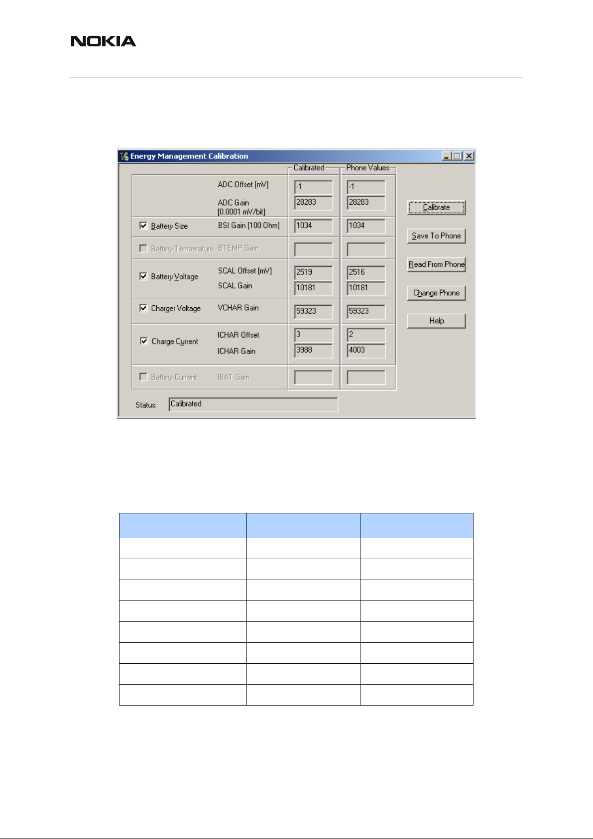
Select “Tuning” and “Energy Management Calibration” in Phoenix menu.
Figure 1:
Selecting energy management calibration with Phoenix.
Issue 1 11/2005 COMPANY CONFIDENTIAL 41
Copyright © 2005 Nokia. All Rights Reserved.
Page 42
RM-127
Nokia Customer Care 3 - Service Software and Tuning Instructions
Select “Calibrate” and save the results by pressing “Save To Phone” when the calibration is finished.
Figure 2: Starting calibration using Phoenix
Check that the values are within the limits given in table below.
Calibration limits
Table 1: BB calibration limits
Parameter Min Max
ADC Offset -50 +50
ADC Gain 26500 28500
BSI Gain 950 1100
Battery Vo ltage Offset 2300 2900
Battery Vo ltage Gain 10000 11000
Charger Voltage 55800 64000
Charger Current Offset -150 +150
Charger Current Gain 3750 4650
42 COMPANY CONFIDENTIAL Issue 1 11/2005
Copyright © 2005 Nokia. All Rights Reserved.
Page 43

RM-127
3 - Service Software and Tuning Instructions Nokia Customer Care
Phoenix Tuning
■ General instructions for tuning
Connect the phone to a PC, which has Phoenix Service Software an d a dongle installed, using
either
• repair jig and DAU-9S (RS232) cable or
• repair jig and XCS-4 cable via FPS-8 flash box or
• DAU-9T cable (RS232).
Connect the phone to a power supply (DC voltage of 3.6V, min. current of 3A) and switch the
phone on.
Start Phoenix Service Software and open FBUS connection.
Select <Scan Product> (Ctrl-R or in menu file <Scan Product>).
Wait until the phone information is shown in the lower right corner of the screen.
Set operating mode to <Local>.
NOTE: PHOENIX automatically selects the product (phone) by scanning when using the CCSdongles, e.g. PKD-1CS or PKD-1. This means all commands
Select Scan Product Ctrl-R
as mentioned in this document are irrelevant!
■ RF tuning after repairs
The screen shots of Phoenix windows displayed in this document showing RH-37, are also valid
for RH-49 and RM-127.
The following tunings have to be performed after repairs:
• Repairs in the TX part will require "TX Power Level Tuning".
• When component replacements around the modulator area (RF path from UEM
via RF ASIC to RF PA) have been done, "TX IQ Tuning" is additionally required.
• In general, repairs in the RX front-end always require "RX Calibration" and “Rx
Band Filter Calibration” for all three bands.
• Repairs in the PLL circuit always require "RX Calibration" of the low band
(GSM900).
• If the RF ASIC was replaced all calibrations mentioned above have to be carried
out.
Issue 1 11/2005 COMPANY CONFIDENTIAL 43
Copyright © 2005 Nokia. All Rights Reserved.
Page 44

RM-127
Nokia Customer Care 3 - Service Software and Tuning Instructions
Table 2: List of necessary tunings after replacement of RF key components and
surrounding R/C/Ls
Tunings/ Calibrations
Key Component Reference No.
Component Designation
Tx Power Level Tuning
Tx IQ Tuning
Rx Calibration
Rx Band Filter Resp. Calib.
Rx Channel Select Filter Calib.
Antenna
Z7800
Switch
xxx
Module
Z7802 SAW 1800 Rx x x
Z7801 SAW 1900 Rx x x
N7500
RF ASIC
(Helgo 8.5)
xxxxx
G7501 VCTCXO x
G7500 VCO x
N7700 TX-PA x x
Z7803 SAW900 Rx x x
Z7700 SAW900 Tx x
Note: When required, the tunings should be pe rfo rm e d in th e followin g or de r :
1. Rx Channel Select Filter Calibration
2. Rx Calibration
3. Rx Band Filter Response Calibration
4.Tx Power level Tuning
5. Tx IQ Tuning
44 COMPANY CONFIDENTIAL Issue 1 11/2005
Copyright © 2005 Nokia. All Rights Reserved.
Page 45

RM-127
3 - Service Software and Tuning Instructions Nokia Customer Care
■ Semi-automatic calibrations and measurements - step by step: RX/TX and
GSM bands
RX channel select filter calibration
In the following, the calibration of the Rx channel select filter (BB-filter) inside the FR-ASIC is
described. It is performed by internal measuring of a proto-type filter. For this reason, the calibration has to be done only once. No RF signal generator is needed. No GSM band has to be
selected in Phoenix.
Rx channel select filter calibration is always the first tuning in the tuning sequence.
Set the operating mode to local mode.
Select Tuning Alt-U
Rx Channel Select Filter
Calibration Alt-H
The setup should now look like this:
The notch value might not be displayed in later Phoenix versions.
Press Tune and the optimal values are found.
Press Stop, the values are saved to the phone and the calibration has finished.
Issue 1 11/2005 COMPANY CONFIDENTIAL 45
Copyright © 2005 Nokia. All Rights Reserved.
Page 46

RM-127
Nokia Customer Care 3 - Service Software and Tuning Instructions
The results must fulfill the following limits:
Calibration value / Test case Typical Low limit High limit
DTOS I Address Rc / check rx baseband
filter DTOS_I [DAC]
DTOS Q Address Rc / check rx baseband
filter DTOS_Q [DAC]
BBF I Address BIQUAD I R / check rx baseband filter BIQUAD_IR [DAC]
BBF I Address BIQUAD I C / check rx baseband filter BIQUAD_IC [DAC]
BBF Q Address BIQUAD Q R / check rx baseband filter BIQUAD_QR [DAC]
BBF Q Address BIQUAD Q C / check rx baseband filter BIQUAD_QC [DAC]
13 -6 +37
13 -6 +37
13 -6 +37
13 -6 +37
21 -6 +37
21 -6 +37
RX calibration GSM900, GSM1800 and GSM1900
The RX calibration has to be performe d to determine gains at dif ferent gain settings in the RF
ASIC. The calibration must be done in all three bands:
RX calibration requires an external RF signal generator. Most of the radio communication testers like CMD 55 or CMU 200 can be used also as RF signal generators, generating continuous
RF signals (CW signal) with defined levels and frequencies.
Note: Depending on Firmware version, the CMU 200 can have problems generating a nonpulsed, non-modulated CW signal.
RX calibration in the GSM900 band combines two alignments: AFC a nd AGC calibrations. The
calibration of GSM 1800 and GSM 1900 bands only determines the AGC values.
The AFC calibration detects an initial AFC value and an AFC slope coefficient. The AFC calibration ensures the proper function of the initial synchronization (base station search, before
location update is done) when the phone has been set to Normal Mode. For an error free initial
synchronization, the 26 MHz frequency of the reference oscillator must be accurate enough.
Therefore, the previously calibrated AFC value is written to the DA converter and the corresponding AFC voltage tunes the VCTCXO to the correct frequency.
The AGC calibration detects the gain values of the RX chain. The RF LNA can be switched
either on or off. The gain difference between on and off state is nominally 30dB and the baseband gain which is controlled by 15 gain steps called in PHOENIX RSSI 0 to RSSI 14 each
having a graduation of 6 dB. The LNA is switched off at the steps RSSI 0 to RSSI 4.
AGC calibration detects the gain at the 3 gain steps RSSI 4, RSSI 5, and RSSI 7. All other steps
are calculated.
A value, RF_TEMP, which represents the RF hardware temperature, is determined during the
RX calibration. This temperature value is used by the DSP for RSSI reporting correction and
Tx temperature compensation in the Normal Mode of the phone. Dependent on the Phoenix
version it might be not displayed while calibrating.
46 COMPANY CONFIDENTIAL Issue 1 11/2005
Copyright © 2005 Nokia. All Rights Reserved.
Page 47

RM-127
3 - Service Software and Tuning Instructions Nokia Customer Care
The Rx calibration has to be done in a temperature of 25°C due to the detection and saving o f
the RF_TEMP value.
The RX calibration is only valid if the results are within defined limits. For the latest specified
limits, please refer to the production limits of the FLALI and FINUI testers' documents.
If the results are not within these limit ranges, the receiver is faulty.
Open the window <Rx Calibration> in Phoenix Service Software as follows:
Select Tuning Alt-U
Rx calibration Alt-C
Phoenix automatically selects the low band.
Press <Start>
The window <Tuning step 1 of 3 – Rx Calibration with band …> pops up informing on power
level of the signal generator and frequency to be set. Do accordingly , after connecting the signal
generator to the antenna port of the test jig respectively to the phone. Compensate for external
RF cable and test jig losses.
If a radio communication tester (CMD 55, CMU 200, HP 8960, MT 8801) is used, assure that
<continuous mode> is switched on and <modulation> switched off.
Press <ok> and the window will close.
The setup should now look like this:
The results must fulfill the following limits:
Issue 1 11/2005 COMPANY CONFIDENTIAL 47
Copyright © 2005 Nokia. All Rights Reserved.
Page 48

RM-127
Nokia Customer Care 3 - Service Software and Tuning Instructions
Calibration value / Test case Typical Low limit High limit
AFC value / check AFC_VALUE [DAC] 53 -350 +350
AFC Slope / check AFC_SLOPE [DAC] 128 90 165
Rssi 4 / Check RX GSM xxx Gain A 5 [dB] 89 (92) 83 (86) 95 (98)
Rssi 5 / Check RX GSM xxx Gain A 6 [dB] 94 (99) 88 (93) 100 (105)
Rssi 6 / Check RX GSM xxx Gain A 7 [dB] 100 (105) 94 (99) 106 (111)
Rssi 7 / Check RX GSM xxx Gain A 8 [dB] 106 (111) 100 (105) 112 (117)
GSM xxx means the selected band: GSM900/GSM1800 or GSM1900 (values in brackets).
If all values are within the low and high limits ranges
Press <Save and Continue>
If one or more of the values are out of the above specified limit ranges, do not save them to the
phone memory. Stop the Rx calibration and repeat troubleshooting.
Otherwise continue Rx calibration according to the tuning steps 2 and 3 for GSM1800 respec-
tively GSM1900 bands. Note the limits of the calibration mentioned in the list above.
Pop up window for Rx calibration of GSM1800 band
Calibration fails and possible reasons:
• If the whole calibration fails, the low band receiver chain (GSM900) or the synthesizer part (including reference oscillator) might be defective.
• If Rssi3 and Rssi6 are within the limits, all other Rssi values are valid, too. If one
of them or both are out of limits, the low band receiver part has to be checked.
• If AFC value or AFC slope fails, but the Rssi values are within the limits, the
VCTCXO G7501 or UEM D200 might be defective.
RX band filter response compensation
This alignment is necessary to compensate the frequency response of the RX band filters
(SAW filters).
48 COMPANY CONFIDENTIAL Issue 1 11/2005
Copyright © 2005 Nokia. All Rights Reserved.
Page 49

RM-127
3 - Service Software and Tuning Instructions Nokia Customer Care
Rx band filter response compensation GSM900, GSM1800 and GSM1900
Manual tuning
Open the window <Rx Band Filter Response Compensation> in Phoenix Service Software as
follows:
Select Tuning Alt-U
Rx Band Filter Response
Compensation Alt-C
Phoenix automatically selects the low band.
Select Tuning mode Manual (Radio Button)
Connect an RF signal generator to the antenna port of the test jig respectively the phone.
If a radio communication tester (CMD 55, CMU 200, HP 8960, MT 8801) is used, assure that
<continuous mode> is switched on and <modulation> switched off.
Compensate for external RF cable and test jig losses.
Make sure that the <Input Signal Level (dBm)> field is set to -60 [dBm].
Press the <Start> button in the <Rx Band Filter Compensation> window.
The setup should now look like this:
(The example below shows a screen shot in GSM900!)
Issue 1 11/2005 COMPANY CONFIDENTIAL 49
Copyright © 2005 Nokia. All Rights Reserved.
Page 50

RM-127
Nokia Customer Care 3 - Service Software and Tuning Instructions
Set the RF signal generator as indicated in the pop-up window on the screen.
Press OK.
Continue tuning steps 2 to 9 following the instructions for power level and signal frequency in-
put.
Press OK after each step.
Note the limits as specified in the table below.
Press Save & Continue
Tune the band filters and save its compensation values to the phone memory for each GSM
band as described above.
50 COMPANY CONFIDENTIAL Issue 1 11/2005
Copyright © 2005 Nokia. All Rights Reserved.
Page 51

RM-127
3 - Service Software and Tuning Instructions Nokia Customer Care
Automatic tuning
A faster and more comfortable method for Band Filter Calibration (BFC) can be performed by
the automatic tuning mode. This requires an RF signal generator that can be internally programmed for sweeping, e.g. Agilent E4421B.
Open the window <Rx Band Filter Response Compensation> in Phoenix Service Software as
follows:
Select Tuning Alt-U
Rx Band Filter Response
Compensation Alt-C
Phoenix selects automatically the low band.
Select automatic in the <Tuning mode> in the <Rx Band Filter Response Compensation> win-
dow.
Connect the RF signal generator to the antenna port of the test jig respectively the phone.
Assure that modulation is switched OFF and RF power continuously ON.
Compensate for external RF cable and test jig losses.
Make sure that the <Input Signal Level (dBm)> field in the Rx Band Filter Response Compen-
sation window is set to -60 [dBm].
Press Start -> the current calibration values from the phone memory are displayed in the col-
umn <Measured Level Difference (dB)>.
The window <Tuning step 1 of 3 …> pops up. Set the RF signal generator according the in-
structions.
The setup should now look like this:
Issue 1 11/2005 COMPANY CONFIDENTIAL 51
Copyright © 2005 Nokia. All Rights Reserved.
Page 52

RM-127
Nokia Customer Care 3 - Service Software and Tuning Instructions
(The example below shows a screen shot in GSM900!)
Press OK for tuning.
The new tuning values are highlighted in the column <Measured Level Difference (dB)>.
Note the limits as specified in the table below.
Press Save & Continue
Tune the band filters and save its compensation values to the phone memory for each GSM
band as described above.
Limits:
The tuned values <Measured Level Difference (dB)> shall not exceed the low and high limits
as specified in the table below.
The typical value in the middle of each GSM band shall be approx. 0 dB, if <Rx Calibration>
was made correctly in the calibration procedure before.
52 COMPANY CONFIDENTIAL Issue 1 11/2005
Copyright © 2005 Nokia. All Rights Reserved.
Page 53

RM-127
3 - Service Software and Tuning Instructions Nokia Customer Care
Channel Number
(as indicated in the < Rx Band Filter Response
Compensation > window)
Meas.
point
GSM900 GSM1800 GSM1900 Low High
(of < Measured Level
Limits
Difference >)
First 965 497 497 -6.0 dB +2.0 dB
N1 975 512 512 -3.0 dB +2.0 dB
N2 987 535 537 -3.0 dB +2.0 dB
N3 1009 606 586 -3.0 dB +2.0 dB
N4 37 700 661 -2.0 dB +2.0 dB
N5 90 791 736 -3.0 dB +2.0 dB
N6 114 870 794 -3.0 dB +2.0 dB
N7 124 885 810 -3.0 dB +2.0 dB
Last 136 908 835 -6.0 dB +2.0 dB
TX power level tuning
RM-127 supports GMSK and EDGE mode for the power amplifier. Therefore, the power level
tuning must be carried out for both modes in each band.
It is strongly recommended to use the Phoenix <Auto-Tune> capability. The functionality of it
is described in chapter “Fully automatic Calibration, Tuning & Measurement by Phoenix
<Auto-Tune>”.
It is strongly recommended to use TXP as external trigger for all TX tunings. External triggering
gives the following advantages:
• trigger for spectrum analyzer (gated sweep)
• trigger for oscilloscope
• trigger for power meter (avoid exchanging of attenuator and getting better accuracy in power measurements)
Nevertheless, manual tuning is described below . It has to be carried out in all three bands and
both modes (EDGE and GMSK).
Note: TX Power Tuning must be done with a peak power meter, e.g. Anritsu model ML2408A
with Anritsu Peak Power Sensor MA2442A and a suitable attenuator.
The use of the built-in power meter of GSM testers is likely to cause larger errors than the use
of a dedicated power meter and might cause miss tuning so that the phone might be not compliant with the GSM specifications.
Set power supply voltage Vcc = 3.6V !
Issue 1 11/2005 COMPANY CONFIDENTIAL 53
Copyright © 2005 Nokia. All Rights Reserved.
Page 54

RM-127
Nokia Customer Care 3 - Service Software and Tuning Instructions
Tx power level tuning GSM900 in GMSK mode
Set the operating mode to local mode.
Select Tuning
TX Power Level Tuning
Wait until the TX Power Level Tuning window is popped up.
Connect a calibrated power meter to the RF connector of the phone.
Press <Start>
On the popped up window press ok
The setup should now look like this:
54 COMPANY CONFIDENTIAL Issue 1 11/2005
Copyright © 2005 Nokia. All Rights Reserved.
Page 55

RM-127
3 - Service Software and Tuning Instructions Nokia Customer Care
Adjust DAC Values for all power levels according to the target values.
The power levels and target values shown in Phoenix may differ from the screenshot above,
due to different PA suppliers.
Make sure that the output power for Power Level 5 is equal or lower than 1dB below the satu-
ration output power. Deter mine the saturation power by setting the DAC value to its maximum,
for example, adjust the DAC V alue to 32.3dBm for Power Level 5 if the saturation output power
is only 33.3dBm.
Check if all levels match the target values, correct if necessary and then press <Save & Continue>.
Tx power level tuning GSM900 in EDGE mode
On the popped up window press ok.
The setup should now look like this:
Adjust DAC Values for all power levels according to the target values.
Check if all levels match the target values, correct if necessary and then press <Save&Contin-
ue>.
Note: For Phones with RFMD power amplifier also the EDGE power level 7 needs to be tuned.
The window (like shown above) will pop up accordingly.
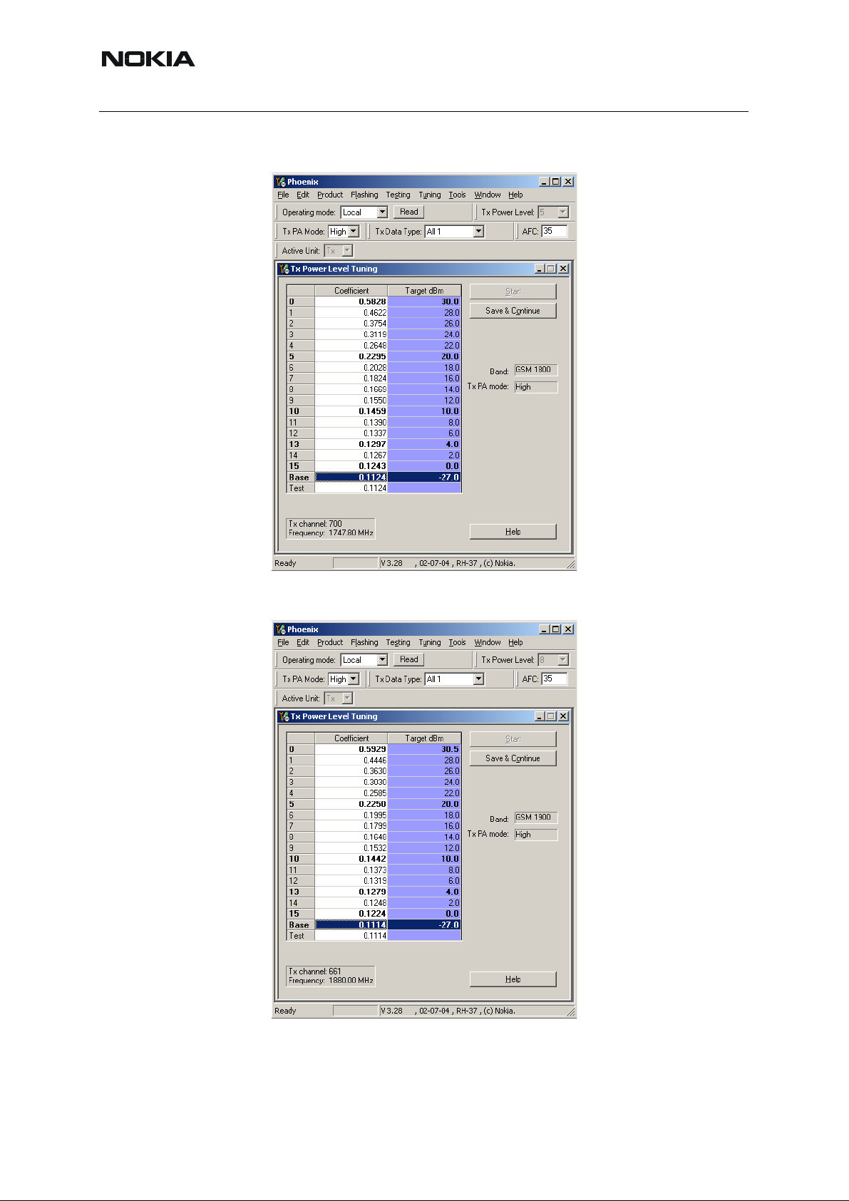
Tx power level tuning GSM1800 & GSM1900 in GMSK mode
On the popped up window, press ok.
Tuning of GSM1800 and GSM1900 work in the same manner, after calibrating the 1800 MHz
band, you start calibrating the 1900 MHz band.
Issue 1 11/2005 COMPANY CONFIDENTIAL 55
Copyright © 2005 Nokia. All Rights Reserved.
Page 56
RM-127
Nokia Customer Care 3 - Service Software and Tuning Instructions
The setup should now look like this:
Adjust the bold marked power coefficients and the base level according to the target values.
56 COMPANY CONFIDENTIAL Issue 1 11/2005
Copyright © 2005 Nokia. All Rights Reserved.
Page 57

RM-127
3 - Service Software and Tuning Instructions Nokia Customer Care
The power levels and target values shown in Phoenix may differ from the screenshot above,
due to different PA suppliers.
Make sure that the output power for power level 0 is equal or lower than 1dB below the saturation output power. Deter mine the saturation power by setting the DAC value to its maximum,
for example, adjust the DAC V alue to 29.7dBm for Power Level 0 if the saturation output power
is only 30.7dBm.
Due to high gain slope, you have to ensure, that especially the lower power levels meet the
target values and correct them if needed.
Check if all levels match the target values, correct if necessary and then press <Save & Continue>.
Issue 1 11/2005 COMPANY CONFIDENTIAL 57
Copyright © 2005 Nokia. All Rights Reserved.
Page 58

RM-127
Nokia Customer Care 3 - Service Software and Tuning Instructions
Tx power level tuning GSM1800 & GSM1900 in EDGE mode
On the popped up window, press ok.
The setup should now look like this:
58 COMPANY CONFIDENTIAL Issue 1 11/2005
Copyright © 2005 Nokia. All Rights Reserved.
Page 59

RM-127
3 - Service Software and Tuning Instructions Nokia Customer Care
Adjust the bold marked power coefficients and the base level according to the target values.
Check if all levels match the target values, correct if necessary and then press <Save & Con-
tinue>.
Proceed with the 1900 MHz band.
TX I/Q tuning
This tuning must be performed in all three bands in GMSK mode and in EDGE mode.
The tuning is carried out exactly the same way in each band and is therefore described only
once.
It is strongly recommended to use TXP as external trigger for all TX tunings. External triggering
gives the following advantages:
• trigger for spectrum analyzer (gated sweep)
• trigger for oscilloscope
• trigger for power meter (avoid exchanging of attenuator and getting better accuracy)
Note: During Tx I/Q Tuning in GSM 900 band, an additional calibration value for the battery voltage A/D converter is taken. Therefore, it is important to set the operating voltage to 3.6 V for this
alignment (and use highest PL).
Ensure that I/Q tuning in GSM 900 band is executed as last I/Q-tuning (every I/Q-tuning overwrites the calibration for the battery voltage).
The VBAT value is detected and saved to PM.
PC/Phone operation:
Set operating mode to Local Mode.
Set supply voltage to 3.6V.
Select Tuning T
TX IQ Tuning I
Wait until the TX IQ Tuning window pops up and press <Start>.
On the popped up window, press ok.
Issue 1 11/2005 COMPANY CONFIDENTIAL 59
Copyright © 2005 Nokia. All Rights Reserved.
Page 60

RM-127
Nokia Customer Care 3 - Service Software and Tuning Instructions
The setup should now look like this:
Connect a spectrum analyzer or GSM tester with the option 'Narrow Spectru m' to the antenna
pads of the phone.
60 COMPANY CONFIDENTIAL Issue 1 11/2005
Copyright © 2005 Nokia. All Rights Reserved.
Page 61

RM-127
A
o
o
3 - Service Software and Tuning Instructions Nokia Customer Care
If a spectrum analyzer is used, make the following settings.
GSM900
Center Frequency 897.4 MHz
Frequency Span 300 kHz
Resolution Bandwidth 3kHz
Video Bandwidth 3kHz
Sweep Time 100 msec.
Sweep Type Clear/Write
Detector Type Max Peak
Reference level 35 dBm
Marker 1 897.33229 MHz
Marker 2 897.4 MHz
Marker 3 897.46771 MHz
The spectrum analyzer now shows a plot like this:
Ref Lvl
Ref Lvl
35 dBm
35 dBm
35
21 dB Offset
30
20
10
0
-10
-20
-30
-40
Marker 1 [T1]
25.88 dBm
897.33229000 MHz
1
2
RBW 3 kHz
VBW 3 kHz
SWT 3 s
1 [T1] 25.88 dBm
897.33229000 MHz
2 [T1] -7.19 dBm
897.40000000 MHz
3 [T1] -11.55 dBm
897.46771000 MHz
RF Att 30 dB
Mixer -20 dBm
Unit dBm
A
LN
1M
3
-50
-60
-65
30 kHz/Center 897.4 MHz Span 300 kHz
Date: 24.OCT.2002 16:26:40
F2
F1
The purpose of this alignment is to tune the carrier signal (at marker 2) and the +67kHz signal
(at marker 3) to a minimum level.
Issue 1 11/2005 COMPANY CONFIDENTIAL 61
Copyright © 2005 Nokia. All Rights Reserved.
Page 62

RM-127
A
o
o
Nokia Customer Care 3 - Service Software and Tuning Instructions
Use the variables 'TX I DC offset' and 'TX Q DC of fset' to adjust the carrier signal to a minimum
level (marker 2). Tuning can be performed by using arrow keys on the keyboard. Pushing the
sliders by using the mouse is less sensitive however possible.
After tuning to the minimum the level difference between marker 2 and the peak levels at marker 1 must exceed 40dB.
The spectrum analyzer now shows a plot like this:
35
30
20
10
Ref Lvl
Ref Lvl
35 dBm
35 dBm
Marker 1 [T1]
25.82 dBm
897.33229000 MHz
21 dB Offset
1
RBW 3 kHz
VBW 3 kHz
SWT 3 s
897.33229000 MHz
897.40000000 MHz
897.46771000 MHz
RF Att 3 0 dB
Mixer -20 dBm
Unit dBm
1 [T1] 25.82 dBm
2 [T1] -21.06 dBm
3 [T1] -11.52 dBm
A
LN
0
-10
-20
-30
-40
-50
-60
-65
Date: 24.OCT.2002 16:30:27
3
2
30 kHz/Center 897.4 MHz Span 300 kHz
1M
F2
F1
Use the variables 'Amplitude difference' and 'Phase difference' to adjust the +67kHz signal to
a minimum level (Marker 3). Tuning ca n be performed by using the arrow keys on the keyboard.
Pushing the sliders by using the mouse is less sensitive however possible.
After tuning to the minimum, the level diffe rence between marker 3 and the peak level at marker
1 must exceed 40dB.
62 COMPANY CONFIDENTIAL Issue 1 11/2005
Copyright © 2005 Nokia. All Rights Reserved.
Page 63

RM-127
A
o
o
3 - Service Software and Tuning Instructions Nokia Customer Care
The spectrum analyzer now shows a plot like this:
RBW 3 kHz
VBW 3 kHz
SWT 3 s
RF Att 30 dB
Mixer -20 dBm
Unit dBm
1 [T1] 25.61 dBm
897.33229000 MHz
2 [T1] -22.44 dBm
897.40000000 MHz
3 [T1] -38.76 dBm
897.46771000 MHz
A
LN
Ref Lvl
Ref Lvl
35 dBm
35 dBm
35
21 dB Offset
30
20
10
Marker 1 [T1]
25.61 dBm
897.33229000 MHz
1
0
-10
-20
-30
-40
-50
-60
-65
Date: 24.OCT.2002 16:33:46
2
3
30 kHz/Center 897.4 MHz Span 300 kHz
Compare the results in the TX IQ Tuning Window with the limits below:
Value Typical Limit min. Limit max.
TX I DC offset 0.1 -6 6
1M
F2
F1
TX Q DC offset 0 -6 6
Amplitude difference 0 -1 1
Phase difference 87.5 78 102
Repeat the IQ tuning for all bands and for all modes by following the instructions from Phoe nix
IQ tuning. Always use the highest power level, otherwise a wrong Vbat value will be stored in
the phone memory.
Note: The optimum values for <TX I and Q Offset> and <Amplitude and Phase Differ ence> vary
from phone to phone.
Please be aware, that the frequency deviation in EDGE mode is 50 kHz, due to the 3 pi / 8
EDGE modulation.
Issue 1 11/2005 COMPANY CONFIDENTIAL 63
Copyright © 2005 Nokia. All Rights Reserved.
Page 64

RM-127
Nokia Customer Care 3 - Service Software and Tuning Instructions
Here you can see an example:
■ Fully automatic calibration, tuning & measurement by Phoenix <Auto-Tune>
Auto-tune is designed to align the phone' s RF p art easier and faster , it calibrates, tunes, measures the following:
• Rx channel select filter calibration
• Rx calibration
• RX band filter response compensation
• Tx power level tuning
• Tx I/Q tuning
and saves the results in a log-file, if wanted.
Autotune is a very user-friendly feature, which allows automatic tuning. Preconditions are:
• usage of CMU200
• usage of XRF-1 cable
• usage of the jig MJ-22
There is no need to adjust any value, since all values are correctly pre-defined in the proper file
delivered with the install-packages.
64 COMPANY CONFIDENTIAL Issue 1 11/2005
Copyright © 2005 Nokia. All Rights Reserved.
Page 65

RM-127
3 - Service Software and Tuning Instructions Nokia Customer Care
Preparations for Phoenix
Follow the instructions as described in chapter General instructions for tuning.
Compensation of cable and jig loses
Measure the losses of the feeding cable(s) between the phone and the Radio Communication
T ester respective the network consisting of RF generator and signal analyze r . The set up of the
measurement equipment and its cabling are shown in the HELP program <Environment
If a separate RF generator and a separate RF analyser is used, a power splitter is needed
which causes higher cable losses. Therefore, the cable losses need to be set via SetLoss. In
CCS Phoenix this is not possible with a PKD-1 dongle, but with a PKD-1CS dongle.
Follow the path: Tuning -> Auto-Tune -> Help -> Environment
Note: Only the proposed measurement equipment listed in <Environment> is supported.
Selecting measurement equipment:
• one Tx and one Rx measurement equipment each from the Tx and Rx lists
or
>.
• one from the Rx/Tx list (only Rohde & Schwarz CMU 200 currently supported)
No mixing of the equipment from the lists [Rx/Tx] and [Tx or Rx] is allowed. This means the use
of CMU 200 allows no other measurement equipment!
The discrete frequencies for loss determinations are defined in the sub-program <set loss>.
Note: <set loss> is accessible with the dongle type PKD-1CS.
Select Tuning Alt-U
Set loss Alt-O
The window <Set loss> pops up with the register card <Cable>.
Issue 1 11/2005 COMPANY CONFIDENTIAL 65
Copyright © 2005 Nokia. All Rights Reserved.
Page 66

RM-127
Nokia Customer Care 3 - Service Software and Tuning Instructions
Edit the column <Loss/dB>.
Note: Jig and product are pre-define d.
GPIB interface
The GPIB card shall be labeled by National Instruments or at least compatible with their products.
Drivers must be installed and card <accepted> by Phoenix. The following procedure has to be
made once for <acceptance> :
Select Tools Alt-T
Options Alt-O
GPIB card Alt-G
The window <GPIB Card> pops up.
Select Card Type NI
Press Start and wait until the <listeners> (radio communication tester) are identified, then
press Close.
The identification may take a few minutes.
66 COMPANY CONFIDENTIAL Issue 1 11/2005
Copyright © 2005 Nokia. All Rights Reserved.
Page 67

RM-127
3 - Service Software and Tuning Instructions Nokia Customer Care
The set up should now look like this:
Automatic tuning procedure
Select Tuning Alt-U
Auto-Tune Alt-A
Tune Alt-T
The <Auto-Tune> results are displayed as follows:
The result values are logged in a result-file, if initiated according to the following chapter.
Issue 1 11/2005 COMPANY CONFIDENTIAL 67
Copyright © 2005 Nokia. All Rights Reserved.
Page 68

RM-127
Nokia Customer Care 3 - Service Software and Tuning Instructions
Log file
To enable the creation of a log file for saving the calibration, tuning and measurement results
Select Tuning Alt-U
Auto-Tune Alt-A
Auto-Tune options Alt-O
Press the button <Enable/Disable logging> ON and select the path of the result file.
68 COMPANY CONFIDENTIAL Issue 1 11/2005
Copyright © 2005 Nokia. All Rights Reserved.
 Loading...