

Page 1
PALplus
FEATURE STEREO
FP-CHASSIS
Service manual
Serviceanleitung
Serviceanvisning
NOKIA 7295 7296 8296
a Manuel de service
a Manuale di servizio
31
rv
1995
NOl<l
CONNECTING PEOPLE
66117203
Page 2
I
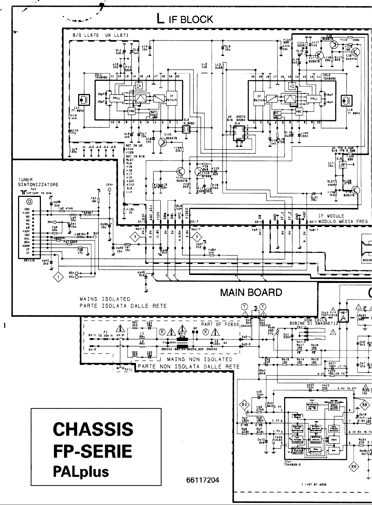
L IF BLOCK
TUNER
SINTONIZZATORE
T"1
lfiHF/UHF 76 WY
E/G LL670 UK LL671
- -- I;
1
LLI
0°C
-
-
-
-
MAINS ISOLATED
PARTE ISOLATA DALLE RETE
'
I
II 1
ik_..,lP~f3TE NON lJuLnln
CHASSIS
FP-SERIE
- - - - ..,.._
MAINS NON ISOLATED
MAIN BOARD
- - - - - -
PART OF
O/A
---------
rcn, *-r* nn,, c nr-rr
---
'i"oii~\\~~
26R
mA’,,T-&--’ n
Xir'ly--
?4
'lo,:" II:'
lCll."I.LI
BOBJoN! DI SMAGNETI
:::"
A r
'14
:I:' . .
PALplus
66117204
Page 3
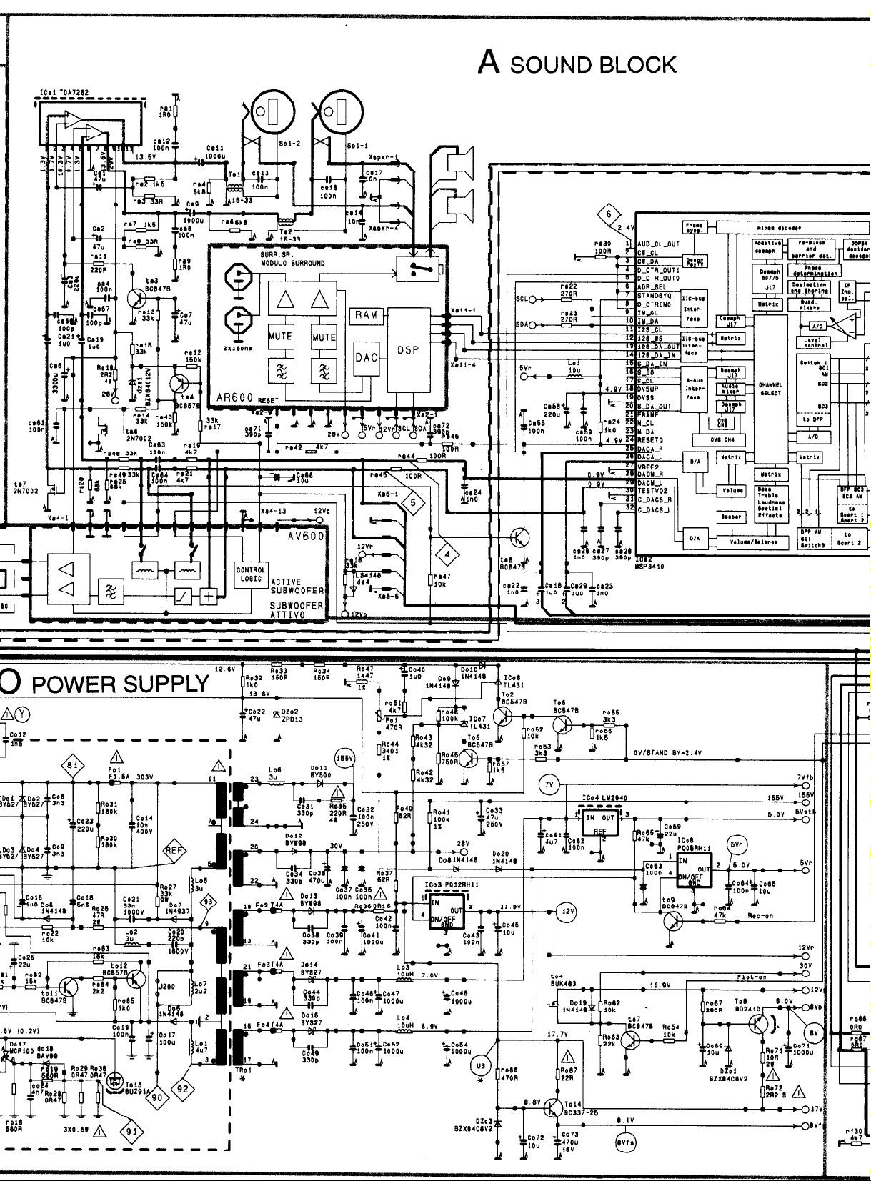
A SOUND BLOCK
A'/600
ACTIVE
SUBWOOFER
SUBWOOFER
Page 4
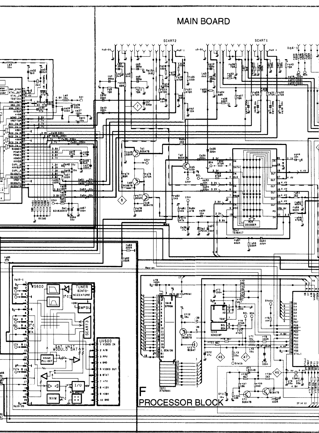
MAIN BOARD
SCAR12
I r: II I 1 I
TU2
BC64
4
SCARTl
ll.-1,
PO ,,
,,
z4
M
UV600
1 VIDEO I"
* AIB
3 WV
I @ND
6 VIDEO OUT
e 8717
, +7v
2 +12v
e +*w
10 bN0
F
4
,fl
Mb47
E
Cl1
27CZOOi
>
T T
I
Page 5
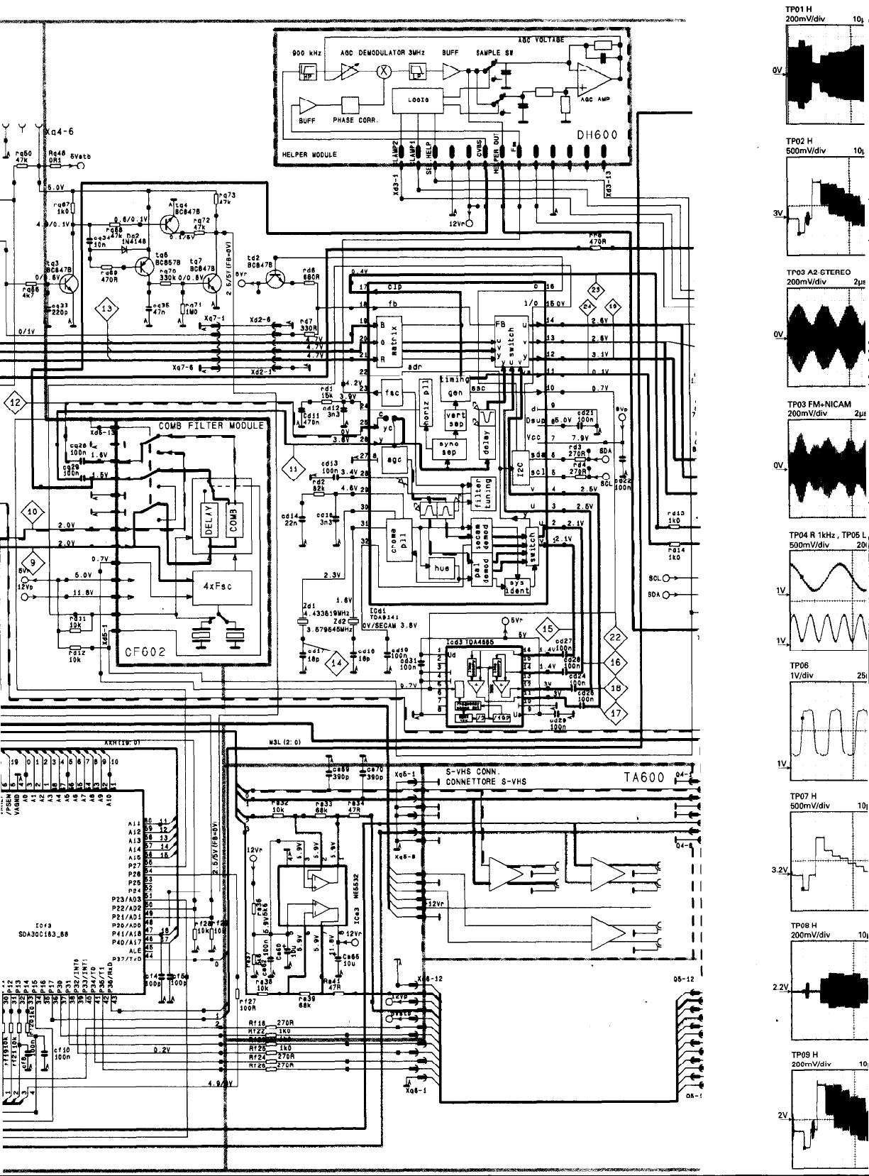
2OOmVldiv
H
h+t
*
101
101
n *
ov
101
-
m
)
iI
U
TPO2 H
5OOmWdii
I f
3V
I
TP03 AZSTEREO
2OOmVldiv
I‘ “i’
TP03 FM+NICAM
200mWdiv
I
i
101
i
2w
2w
TP04 R 1 kHr , TP05 L
5OOmVIdiv 201
I f
I
\
I
\
I
\
I
\
TP06
lV/div 251
TP07 H
5OOmWdiv
TP08 H
2OOmVldiv
TP09 H
2OOmVldiv
,
I,,, ;
Page 6
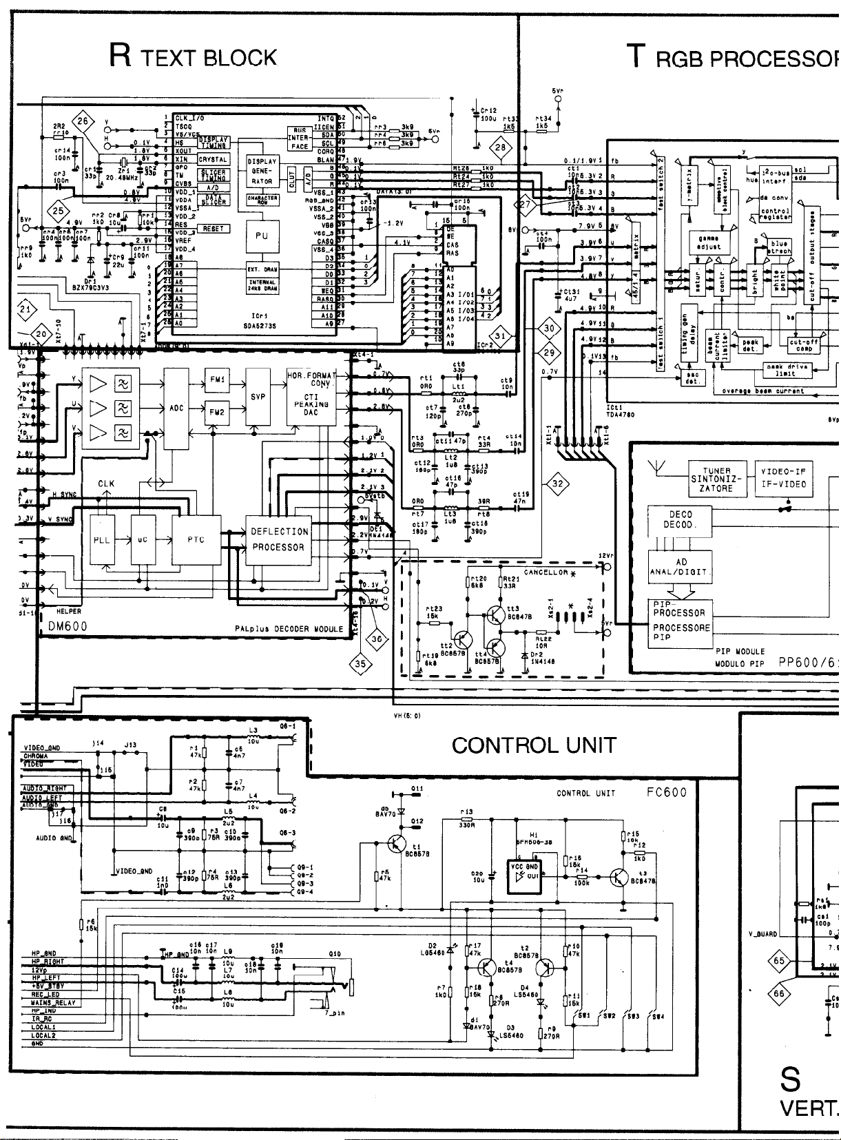
R TEXT BLOCK
PROCESSOF
VERT.
T RGB
“H 6: 0)
32
0
CONTROL UNIT
CONTROL UNIT
DECO
DECOD.
AD
ANAL/DIGIT
i/JPIPPROCESSOR
- PROCESSORE
PIP
-PIP UODIJLE
UODULO PIP PP600/6:
Page 7
H CRT MODU
1
7’
G5
-;.
I
4
I
I
c !.
I
4
I
I
cc E
I
lE.___
I
Ck5b
470”
1
Xk2- 1
i +
+
-w-v
I
I
I
I
I
CND -
I
I
I I- -cl.!
,li
Page 8
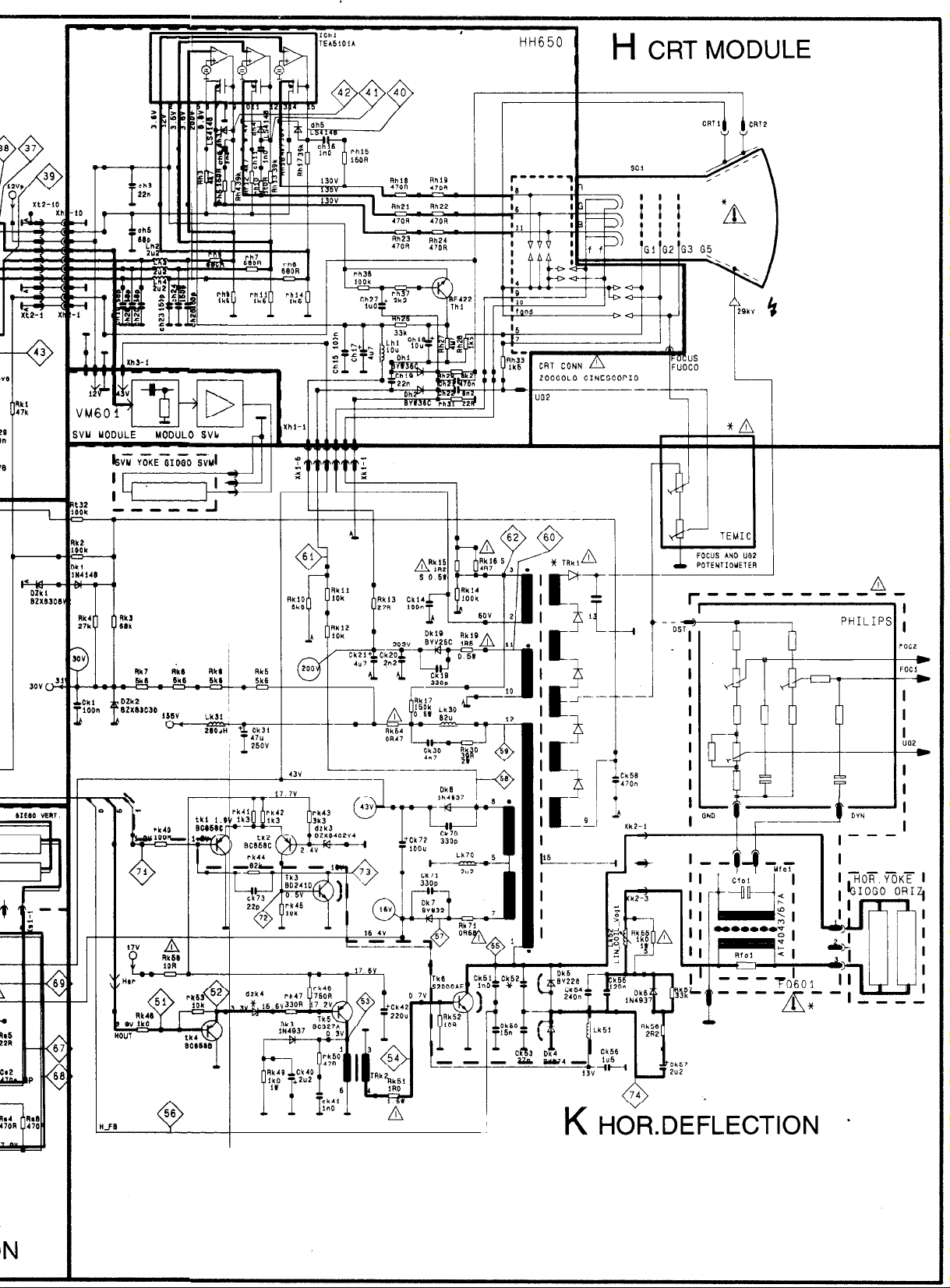
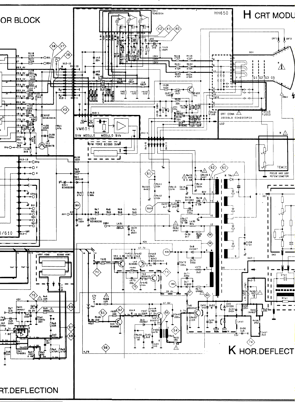
HH650
H CRT MODULE
1 ZOCCOLO CINESCOPIO
-i
I
I ‘I
- os-
t
_ I
I
I
I
I
I
I
I
I
I
I
PHILIP:
l
I
‘CC2
-_)
:CC1
--m
I
I
I
“02
4
I
I
K HOR.DEFLECTION -
Page 9

d-AZ
xx933 al
‘W-AS
III Ir-
l-t-
JI
ji
paselos! uou su!elly
r’-‘-‘-“““.~.~.~
I ,
E
. .
*)-A8
9
I
Page 10

Tul
Helper
Icnmh filtnrlll
__...- ..--.
I
_. __._.
251
COMPF
H V
155vvI Trkl
Horizontal
Page 11

Subwmfer
1 _ . _I Sound proces. 1
FEATURE1 Surround
q Local Control 1
RC Receiver
AJD -Status 2
A/D =+ Status 1
A/D s RGB Status
20 1 Hold
M3L
,t 24 I
7
- -
---
364
I
SERVICE MODE SELECTION:
Switch on the rece,iver by pressing the mains switch and within
5 s. press the remote control buttons MENU, TV and 7”
successively.
WAHL DES SERVICE-MODUS:
Einschalten Sie das Gerat mit dem Netzschalter und innerhalb
5 Sekunden Driicken Sie nacheinander die
Fernbedienungstasten MENU, TV und “i”.
VAL AV SERVICE-LAGE:
Sla pa mottagaren med huvudstrombytaren och inom 5 s. tryck
pa fjarrkontrollens MENU, TV och ‘7” knappar succesivt.
SELECTION DU MODE SERVICE:
Mettre le recepteur en marche a I‘aide de I’interrupteur
principal et dans les 5 secondes appuyez successivement sur
les touches MENU, TV et ‘7” de la telecommande.
SELEZIONE DEL MOD0 SERVIZIO:
Accendere il ricevitore tramite I‘interruttore generale e
premendo in sequenza i tasti del telecomando MENU, TV e ‘7”
entro 5 secondi.
A menu
[TV
@iii_+=
B menu
4
Page 12

A menu
Language selection
1.
Press the MENU button (under the lid).
2.
Select the INSTALLATION with the cursor buttons (up-/
downwards) and press the OK button.
Select the LANGUAGE and press the OK button.
3.
Select the desired language and press the OK button.
4.
Press the TV button to exit.
5.
Manual tuning
1. Select programme number you want to tune.
2. Press the MENU button.
3. Select MANUAL TUNING and press the OK button.
4. Press red button (SEARCH).
5. Press the OK button to store.
6. Press the TV button to exit.
APSi (Automatic Programming System)
1. Press the MENU button.
2. Select INSTALLATION and press the OK button.
3. Select REPROGRAMMING and press the OK button.
4. To retune the channels, press the OK button.
5. Press the TV button to exit.
B menu
Language selection
1. Press the PRG button.
2. Select the Install by pressing the blue button.
3. Select the Language by pressing the red button.
4. Select the desired language with the cursor buttons and
press the OK button.
5. Press the TV button to exit.
Manual tuning
1.
Press the PRG-button.
2.
Press the red button (Tune).
3.
Press the red button (Search).
4.
Select the prog. number on which the channel is to be
stored.
Press the blue button (Store) to store.
5.
Press the TV button to exit.
6.
5. Press the green button (Reprog).
6. Press the blue button (OK) to exit.
NVRAM (ICf2)
Installation of NVRAM
In case that the NVRAM is replaced, it must be initialized and
configurated.
1.
Set the receiver to the service mode by switching on the
receiver with the main switch and within 5 s. pressing the
buttons MENU, TV and “i” successively.
Note! The receiver is in the service mode although it looks
like the receiver is in stand-by mode!
2.
lnitialize the NVRAM by pressing the RED button. The green
LED flashes once. Wait approx. 15 s. When the initialization
is completed, the green LED will light up.
3.
Switch off the receiver by pressing the mains switch.
4.
Start the receiver to the TV mode by pressing the main
switch. Tune in one or more tv channels.
5.
Switch off the receiver by pressing the mains switch.
6.
Start the receiver into the service mode. If the receiver
remains in stand-by mode, press the TV button twice and
then press the “i” button.
7.
Configurate the receiver by pressing the RED button. The
configuration menu will show up.
8.
Press the OK button.
9.
After that make all of the service adjustments (see section
“SERVICE ADJUSMENTS VIA IIC BUS”).
lO.Switch off the receiver by pressing the mains switch.
Re-initialization of NVRAM
For example when the receiver doesn’t start to normal picture,
the NVRAM may need re-initialization.
1.
Set the receiver to the service mode by switching on the
receiver with the main switch and within 5 s. pressing the
buttons MENU, TV and “i” successively.
Note! The receiver is in the service mode although it looks
like the receiver is in stand-by mode!
2.
Select the initialization of the NVRAM by pressing the RED
button. The green LED will light up. Wait approx. 2 s. After
that, press the BLUE (then wait approx. 2 s.), 2, 5 and 4 (then
wait approx. 2 s.) buttons.
3.
Press the OK button to initialize the NVRAM. lnitialization
will take approx. 15 s.
4.
Switch off the receiver by pressing the mains switch.
5.
Start the receiver to theTV mode by pressing the main
switch. Tune in one or more tv channels.
6.
Switch off the receiver by pressing the mains switch.
7.
Start the receiver into the service mode. If the receiver
remains in stand-by mode, press the TV button twice and
then press the “i” button.
8.
Configurate the receiver by pressing the RED button. The
configuration menu will show up.
9.
Press the OK button.
lO.After that make all of the service adjustments (see section
“SERVICE ADJUSMENTS VIA IIC BUS”).
1 l.Switch off the receiver by pressing the mains switch.
APSi (Automatic Programming System)
1. Press the PRG button.
2. Press the blue button (Install).
3. Press the yellow button (Reprog).
4. Press the red button (APSi).
Page 13

SERVICE MODE SELECTION
1. The receiver is set to the service mode by switching
on the receiver with the main switch and within 5
seconds pressing the remote control buttons MENU,
TV and “i” successively.
Note! If the receiver remains in stand by mode after
selecting the service mode, switch on the receiver by
pressing the TV button twice and select the service mode
by pressing the “i” button.
IPTION BYTE DESCRIPTIONS
(
Option bits to be set automatically:
(
Description
E
3it
TV tuner
(
1
Decoder TDA9141
L
Deflection controller TDA9151
RGB processor TDA4780
E
Video switch TDA6417
z
PIP controller SDA9188
;
Setting ‘1’ ‘0’
Yes No
Yes No
Yes No
Yes No
Yes No
Yes No
In the service mode an adjustment menu (including the
adjustment number and name, initializing (left) and
adjustment (right)) values is shown on the screen.
2. Return from the service mode by switching off the
receiver with the main switch.
CONFIGURATION AND FAULT DIAGNOSIS
The set must be configurated after adding or removing
some options. By pressing the red button in the service
mode, the processor checks all possible addresses of bus
driven circuits and shows the settings on the screen.
This feature can also be used in fault finding; if an option
bit is not “1” when it should be or if it is not possible to
set it to “1” by using the number buttons, the IC is either
not present or faulty.
Changing of option bytes
1. When in service mode, select the configuration mode
by pressing the red button.
PIP tuner
(
1
Megatext SDA5273
1
!
7
MSP3400 / 3410
(
DSP (surround)
I
Subwoofer
1
Display processor SDA9280
2
PALplus processor 187C752
3
1
Comb filter (SVHS line low)
3
(
3
3 Loudspeaker configuration (Set in user mode)
t
TXT with external RAM
0
NTSC 3.58 MHz
4
B/G system
0
1
I system
2 D/K system
3 L/L’ system
Baseband
5
Yes No
Yes No
Yes No
Yes No
Yes No
Yes No
Yes No
Yes No
Yes No
Yes No
Yes No
Yes No
Yes No
Yes No
Yes No
Description
SW VER. = PP software version.
NVM VER. = NVM software version.
Select IIC Device byte 1 - 4 or Option byte 1 - 5 with
the cursor button (up-/downwards). Selected byte is
shown highlighted.
Set the bits with the number buttons (0 . . 7).
Store the settings by pressing the OK button.
Return to the service mode by pressing the red button
again.
Option bits to be set manually:
Description
Bit
4
Bass splitting
Pre-equalization for surround DSP
6
Flof text enabled
2
Camera connector installed
0
NICAM enabled
6
7
Loudness enabled
fF W-i?~: rs;? ,)IIIIIIIIIIIII~ "1
Only UHF tuner
7
Setting ’ ’ ‘0’
1
Yes No
Yes No
Yes No
Yes No
Yes No
Yes No
Yes No
Page 14

REMOTE CONTROL BUlTONS IN SERVICE MODE
When the receiver is in service mode you can select the
normal TV mode by pressing the TV button and return
to the service mode by pressing the “i” button.
Number and cursor buttons are used for service
adjustment. The yellow button hides temporarely the
service menu. The OK button stores the settings.
Note! Before other adjustments Ul voltage must be adjusted.
Adjustment for different picture format
First make all adjustments with normal 4:3 picture
format. The TV uses these adjustment values for all
picture formats if no other adjustment were made. In
each adjustment it is mentioned if the adjustment must
be done separately for different picture format, repeate
only those adjustments.
Note! The picture geometry adjustments must be done
with 16:9 picture format.
Making the service adjustment
1. Give a two numbered code which determines the
adjustment (e.g. 05 = horizontal phase, see the
following tables) with the number buttons.
Note! The adjustments can also be selected with the
cursor button (up-/downwards).
2. Adjust with the cursor button (left/right).
3. Store the new value by pressing the OK button.
Note!
l To avoid incomplete adjustments store each
adjustment in the memory immediately after adjusting.
l If the adjustment has to be made separately for diffe-
rent picture format, select the normal user mode by
pressing the TV button and change the picture format
with the zoom button. Return to service mode by
pressing the the “i” button.
VERTICAL PICTURE ADJUSTMENTS
Adjustment
Vertical amplitude
Vertical off-centre shift
Vertical start scan
Vertical S-correction
Vertical slope 4:3 zoom (coarce)
Vertical slope 4:3 zoom (fine)
Center value, 4:3 zoom shift
(V-wait)
Zode
00
01
02
03
12
13
14
OSD
name
V-ampl.
V-shift
V-start
S-corr.
Zoom-H
Zoom-L
Shift
HORIZONTAL PICTURE ADJUSTMENTS
Adjustment
EW width
Horizontal phase
H-phase RGB
H-phase RGB zoom
(
Zode OSD
name
04 Width
05 H-shift
Init.
value
43
3
6
27
71
0
28
init.
value
35
27
Note!
Adjust the picture height to correct ratio.
Adjust the color edge to the center of the picture.
Adjust the lower part of the picture to correct ratio.
Separate adjustment for 4:3 format!
Select 4:3 zoom picture format and adjust the
picture to correct ration.
Separate adjustment for 60Hz NTSC
transmission!
Before adjustment select 4:3 zoom picture
format!
Note!
Separate adjustments for normal 4:3, H-phase zoom
4:3 zoom and full screen picture format (either 4:3
zooml, 4:3 zoom2, 16:9 or PALplus format; adjust
with only one of these picture formats)!
In addition make same adjustments by using RGB
signal!
EW parabola
EW corner
EW trapezium
EHT compenzation
06 Parab.
07 Corner
08 Trapez
09 EHT
13
0
2
36
Set brightness and contrast to 90% and compensate
the change in oicture size.
Page 15

OTHER ADJUSTMENTS
Adjustment
Red gain
Green gain
Blue gain
Red reference
Green reference
Blue reference
Code OSD
name
R gain
17
18 G gain
B gain
19
R ref.
20
21 G ref.
22 B ref.
Init. Note!
value
41 This procedure is necessary e.g. when the picture
tube, CRT-module etc. has been replaced!
32
Apply a test picture and adjust the R, G and B
32
references.
Then adjust the R, G and B gains.
52
21
16
Clamp shift
Peak white limit
Gamma correction
Tuner AGC
CTI length
CTI sensitivity
Chrominance / luminance delay
Black curtain, right edge
Black curtain, left edge
11 Clamp 0
23 PWL 63
24 GAMMA 32
25 TVAGC 170
26 CTI LEN 15
27 CTI SENS 7 Normally no need to adjust.
28 Y 138 7
29 BCK POS 201
BCK WID 90 Normally no need to adjust.
30
0 POWER SUPPLY BLOCK
Supply voltage WI 1 and protection circuit
Set-brightness and contrast to normal level. Connect
an universal voltmeter to the cathode of Do1 1.
Adjust with Pol the DC voltage (Ul) for +I55 V (+I V).
Check the over-current protection after making any
service operations in the primary circuit of the power
supply. Set the receiver to the stand-by mode. Short
circuit the cathode of Do 13 to the ground and keep
the short circuit connected. When the over-current
protection works correctly, the power supply stops.
Remove the short circuit and switch on the receiver by
pressing the mains button.
Normally no need to adjust.
Normally no need to adjust.
Normally no need to adjust.
Apply a 1 mV (60 dBpV) test signal. Adjust the
picture just without noise.
Normally no need to adjust.
Normally no need to adjust.
Separate adjustment for RGB signal and PALplus
picture!
Normally no need to adjust.
LL PICTURE AND SOUND IF MODULE
Video demodulator
1. Apply a test signal (1 mV = 60 dBkV).
2. Connect an universal voltmeter to the module
connector Xl pin 6.
3. Adjust with LL6 the DC voltage to the point where it
changes from 0 to 5 V.
Sound demodulator
Apply a CCIR B/G standard (FM modulated sound) test
signal.
Connect a universal voltmeter to ICLI pin 13.
HORIZONTAL DEFLECTION BLOCK
Focusing
Set brightness to normal level and contrast to high level.
Use cross hatch pattern and adjust the picture for
optimum resolution.
(Screen grid voltage) Ug2 voltage
1. Set contrast to minimum, brightness and colour
saturation to normal level.
2. At the end of the vertical blanking, there is a black
current measurement pulse (clamp pulse) at pins 9, 12
and 15 of IChl. Use an oscilloscope and find the
output stage with the highest cut-off (ie. the highest
voltage during the black current measurement pulse).
3. Adjust the voltage of the clamp pulse to +I40 V with
ug2.
Adjust with LLI the DC voltage for +3,7 V.
.-.--I
Clamp pulse
ov
Note! Adjust the voltage with clamp pulse.
r
40 v
Page 16

r
;;
_n
P
-I
Page 17

,tp59
icau3
HCFU853B
J
1~52
Page 18

tpu3
7” ‘F
tp19
T I
-
T T T T I
I I
I I_
SC29
T
I
GND _ - 1
tp15 tp59
c-out - =
tp1u tp's
r_out
tpyftp57
GNG c _ A
GNG
l@l
CAlI
tp59
d
to3
BC9U79
tPl8
m
I
1
rc6
22mt 17
-
-4-l v
t
n
‘f
t
tp5e
I I tn59
I
00290026Co27
199n199n 1984
I?'
Page 19

--I--
61’4P=’
“eel 1
BE’(PJ
LIZ
I
IEqPd
L12
hdl
iE’4 sS’4
i-I_
av4Po
SZ’IPJ “881
IqPl
TlZqPO
‘Jzz
E*E
T
I
sdl 6hdl
2qPl
IZYPO
9%
I
T
SZ’IP
dLz
I
2h"l
Elr(PI
aLsa3a
hWPJ :
6895
ursdl
ZEL(P-’
LleEE
Ll22
zsdt
SE’IPJ
ssd
ssd
s2qp-l
481
T T
191
61’4P.
L
*
Ld
I
SI’IPI
aLha3a
7
Ih’4PJ
IEI
Y--
LlrlPl
12’4
ELheJa
SWPJ
LI’IPO
le6E
I e !L(PJ
Page 20

-162
4k7
l-156
U7k
t12
BC6176
T
161
1k7
dl6Lsulue
LA
TN -
x1-7
*
t
,I
I
+1u9
CL2
I
:,-,I 1 1 1 j T (X2-7
E E
I I
L
is
Page 21

Page 22

TPl
TP13
nl
. . .,. . -
CVM60 UM8 . CJUVY~L~~V~~~
I’
Page 23

Page 24

1 PALl;ls DECODER MODULE 1 5611720#
 Loading...