

Page 1

Nokia Customer Care
6(b) - RF Troubleshooting
6(b) RF Troubleshooting
Instructions
and Manual Tuning
ISSUE 1 11/04 Copyright © 2004 Nokia. All Rights Reserved.
Page 2

RM-14
Nokia Customer Care RF Troubleshooting and Manual Tuning
[This page left intentionally blank]
2 COMPANY CONFIDENTIAL ISSUE 1 11/04
Copyright © 2004 Nokia. All Rights Reserved.
Page 3

RM-14
RF Troubleshooting and Manual Tuning Nokia Customer Care
Table of Contents
Page No
Introduction .........................................................................................................5
Notes on reference measurements.................................................................... 5
Helgo / Synthesizer Troubleshooting................................................................6
N500 Helgo troubleshooting .............................................................................. 7
Synthesizer troubleshooting............................................................................... 8
Tx Troubleshooting............................................................................................. 9
Tx 900 GMSK troubleshooting......................................................................... 10
Tx 1800/1900 GMSK troubleshooting.............................................................. 11
Rx Troubleshooting ..........................................................................................12
Rx 900 troubleshooting.................................................................................... 13
Rx 1800 troubleshooting. ................................................................................. 14
Rx 1900 troubleshooting. ................................................................................. 15
Bluetooth / FM Radio Troubleshooting........................................................... 16
Bluetooth troubleshooting................................................................................ 17
FM radio troubleshooting................................................................................. 18
Service Tool Concept for RF Tunings .............................................................19
Service concept for RM-14 RF tunings............................................................ 20
Receiver Tunings............................................................................................... 21
RX channel select filter calibration................................................................... 21
RX calibration................................................................................................... 22
EGSM900 band ............................................................................................. 22
GSM1800 band ..............................................................................................24
GSM1900 band ..............................................................................................25
RX band filter response compensation............................................................ 26
EGSM900 band ............................................................................................. 27
GSM1800 band ..............................................................................................30
GSM1900 band ..............................................................................................31
T ransmit ter Tunings.......................................................................................... 33
TX power level tuning ...................................................................................... 33
EGSM900 PA High Mode with EDGE off .......................................................34
EGSM900 PA high mode with EDGE on ....................................................... 35
GSM1800 PA high mode with EDGE off ........................................................36
GSM1800 PA high mode with EDGE on ........................................................37
GSM1900 PA high mode with EDGE off ........................................................38
GSM1900 PA high mode with EDGE on ........................................................39
TX I/Q tuning.................................................................................................... 40
ISSUE 1 11/04 COMPANY CONFIDENTIAL 3
Copyright © 2004 Nokia. All Rights Reserved.
Page 4

RM-14
Nokia Customer Care RF Troubleshooting and Manual Tuning
EGSM900 band with EDGE Off .....................................................................40
EGSM900 band with EDGE On .....................................................................42
EGSM1800 band with EDGE Off ...................................................................42
GSM1800 band with EDGE On .....................................................................42
GSM1900 band with EDGE Off .....................................................................42
GSM1900 band with EDGE On .....................................................................43
List of Figures
Page No
Fig 1 Helgo/Synthesizer........................................................................................6
Fig 2 PA/TX........................................................................................................... 6
Fig 3 Helgo/Synthesizer........................................................................................9
Fig 4 PA/TX........................................................................................................... 9
Fig 5 TX 900 GMSK troubleshooting ....................................................................10
Fig 6 TX 1800/1900 GMSK troubleshooting .........................................................11
Fig 7 Helgo/Synthesizer........................................................................................12
Fig 8 PA/TX........................................................................................................... 12
Fig 9 RX 900 troubleshooting................................................................................ 13
Fig 10 RX 1800 troubleshooting............................................................................ 14
Fig 11 RX 1900 troubleshooting............................................................................ 15
Fig 12 Bluetooth/FM.............................................................................................. 16
Fig 13 Bluetooth troubleshooting ..........................................................................17
Fig 14 FM radio troubleshooting ...........................................................................18
4 COMPANY CONFIDENTIAL ISSUE 1 11/04
Copyright © 2004 Nokia. All Rights Reserved.
Page 5

RM-14
RF Troubleshooting and Manual Tuning Nokia Customer Care
Introduction
This document is the troubleshooting guide for RM-14. On the following pages you will find a
step-by-step fault finding procedure and reference measurements at the relevant signal points.
Note! Most test points are not accessible unless shielding cans are cut open.
This must ONLY be done by the Return Analysis technicians and for analysis
only!
■ Notes on reference measurements
• LF & DC signals are measured with Textronix 100 MHz Scope (TDS3014) and
P3010 13pF probe.
• RF signals are measured with R&S FSIQ 7GHz Spectrum Analyzer and Agilent
resistive divider probe (10dB, 500ohm).
• Please be aware that the RF connector on service adaptor is leaking power (into
air) and acts as noise source when probing on RX chain. In 1800 band the problem
is most severe while there is no external LNA to amplify the signal above the noise
level like in the 1900 band. In 900 band the leakage is not as high due to lower frequency.
• GSM SA settings: RBW=500kHz, VBW=500kHz.
• Bluetooth SA settings: RBW=2MHz, VBW=2MHz.
• All reference measurements were made on a RM-14 phone (GSM900).
• RF loss Module Repair Jig: 900: 0.6 dB, 1800: 1.1dB and 1900: 1 .2dB. Bluetooth
is 1.8dB.
ISSUE 1 11/04 COMPANY CONFIDENTIAL 5
Copyright © 2004 Nokia. All Rights Reserved.
Page 6
RM-14
Nokia Customer Care RF Troubleshooting and Manual Tuning
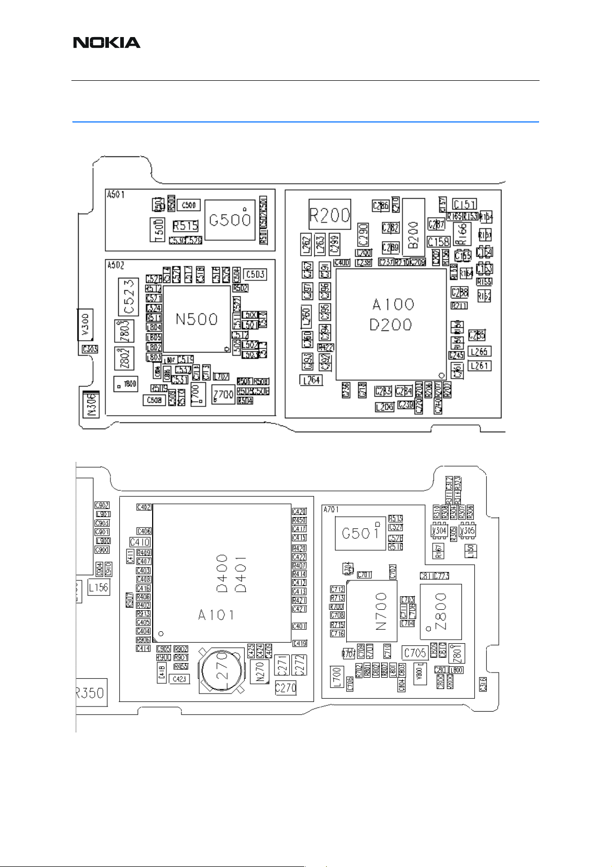
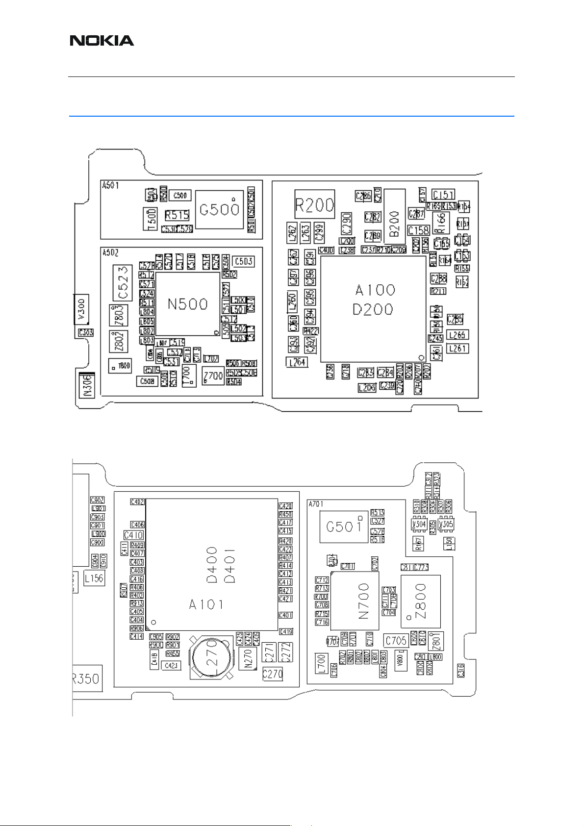
Helgo / Synthesizer Troubleshooting
Figure 1:Helgo/Synthesizer
Figure 2:PA/TX
6 COMPANY CONFIDENTIAL ISSUE 1 11/04
Copyright © 2004 Nokia. All Rights Reserved.
Page 7
RM-14
RF Troubleshooting and Manual Tuning Nokia Customer Care
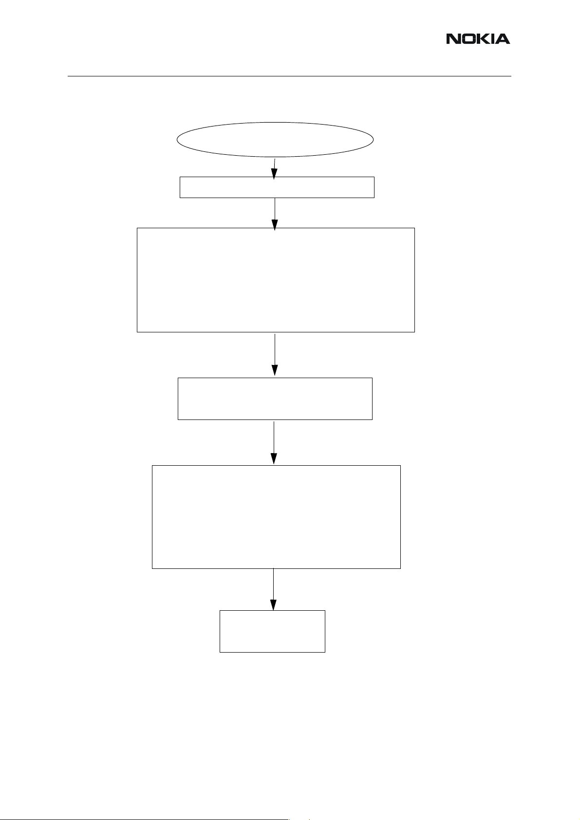
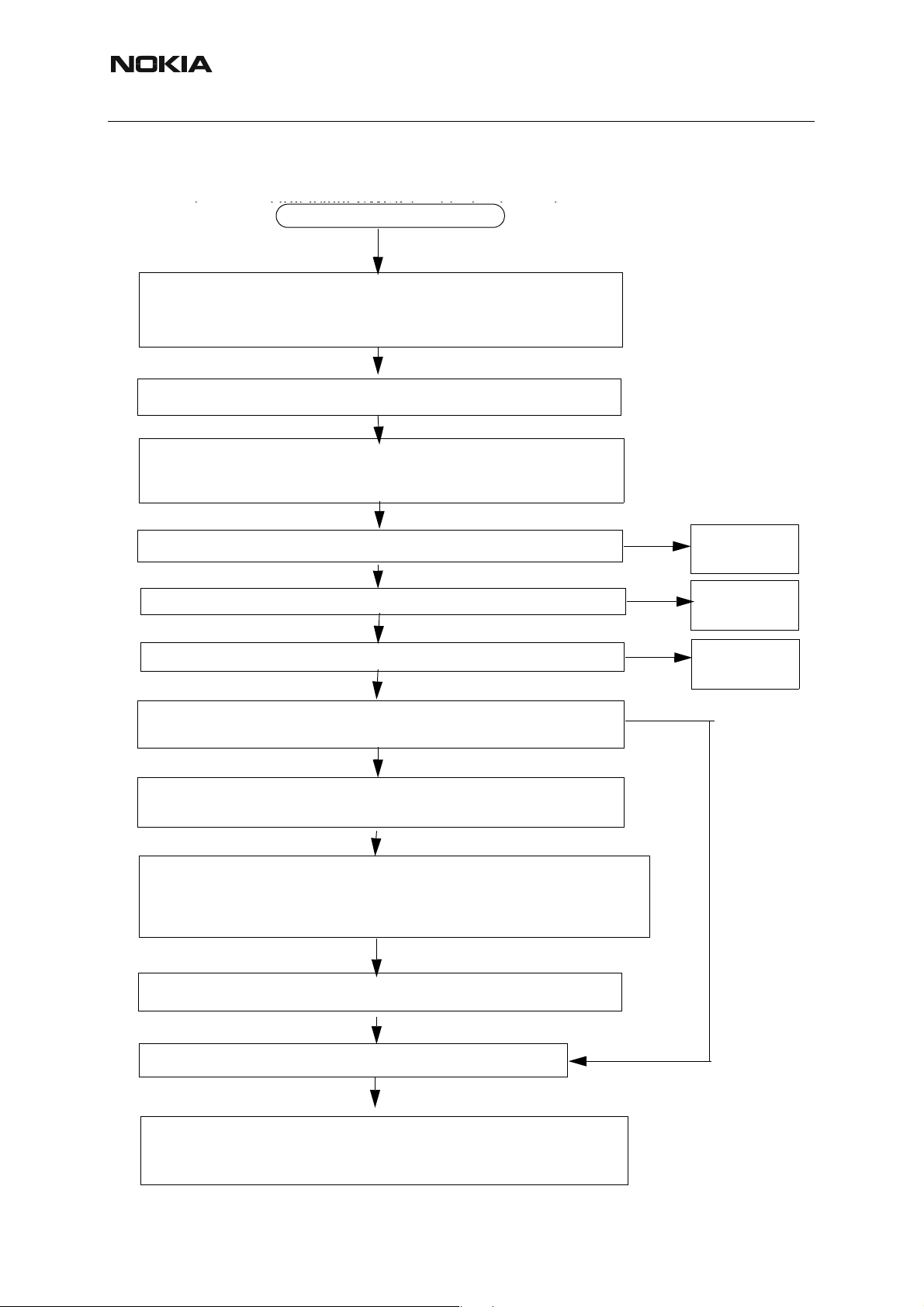
■ N500 Helgo troubleshooting
N500 HELGO troubleshooting
Set Phoenix to RF local burst RX mode
Measure N500 Helgo supply voltages:
- VR1 at C551 - 4,75V?
-VR1 at C516 - 4,75V?
- VR2 at C520 - 2,8V?
-VR2 at C510 - 2,8V?
- VR3 at C503 - 2,8V?
-VR3 at C522 - 2,8V?
- VR4 at C554 - 2,8V?
-VR4 at C520 -2,8V?
- VR5 at C553 - 2,8V?
-VR5 at C518 -2,8V
- VR6 at C555 - 2,8V?
-VR6 at C521 -2,8V?
- VR7 at C297 - 2,8V? (located at BB bottom grid S3)
-VR7 at C500 -2,8V?
Measure N500 reference voltage:
VrefRF01 = 1,35V (C549)
1,44V
(C524)
Measure N500 serial bus signals
- RfBusClk at J501
- RfBusEna1 at J502
- Reset at J503
- RfBusData at J509
All measured in Burst Mode
.
Logic high level = 1,8V.
NOK
Check baseband.
ISSUE 1 11/04 COMPANY CONFIDENTIAL 7
Copyright © 2004 Nokia. All Rights Reserved.
Page 8
RM-14
R420
7
Nokia Customer Care RF Troubleshooting and Manual Tuning
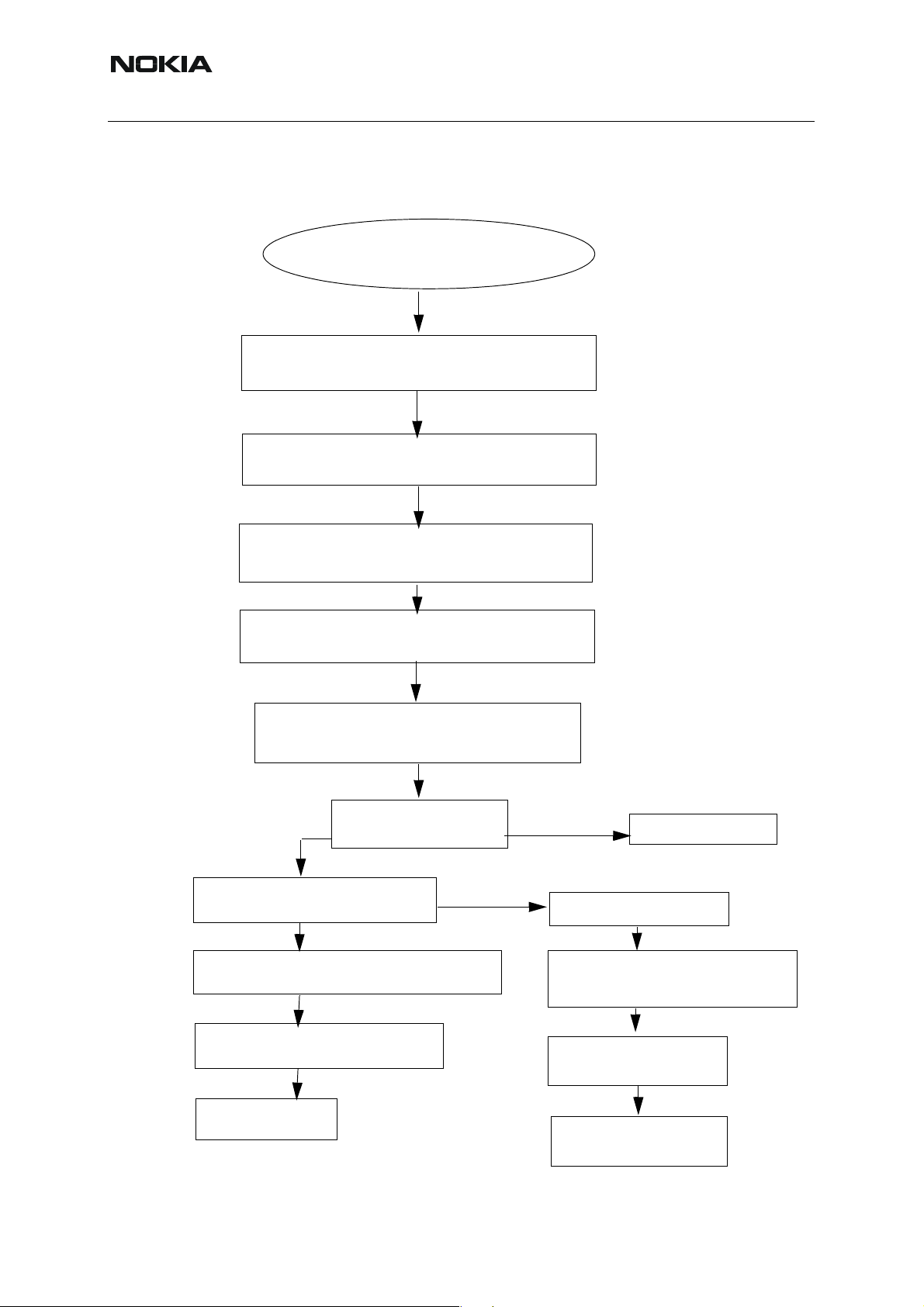
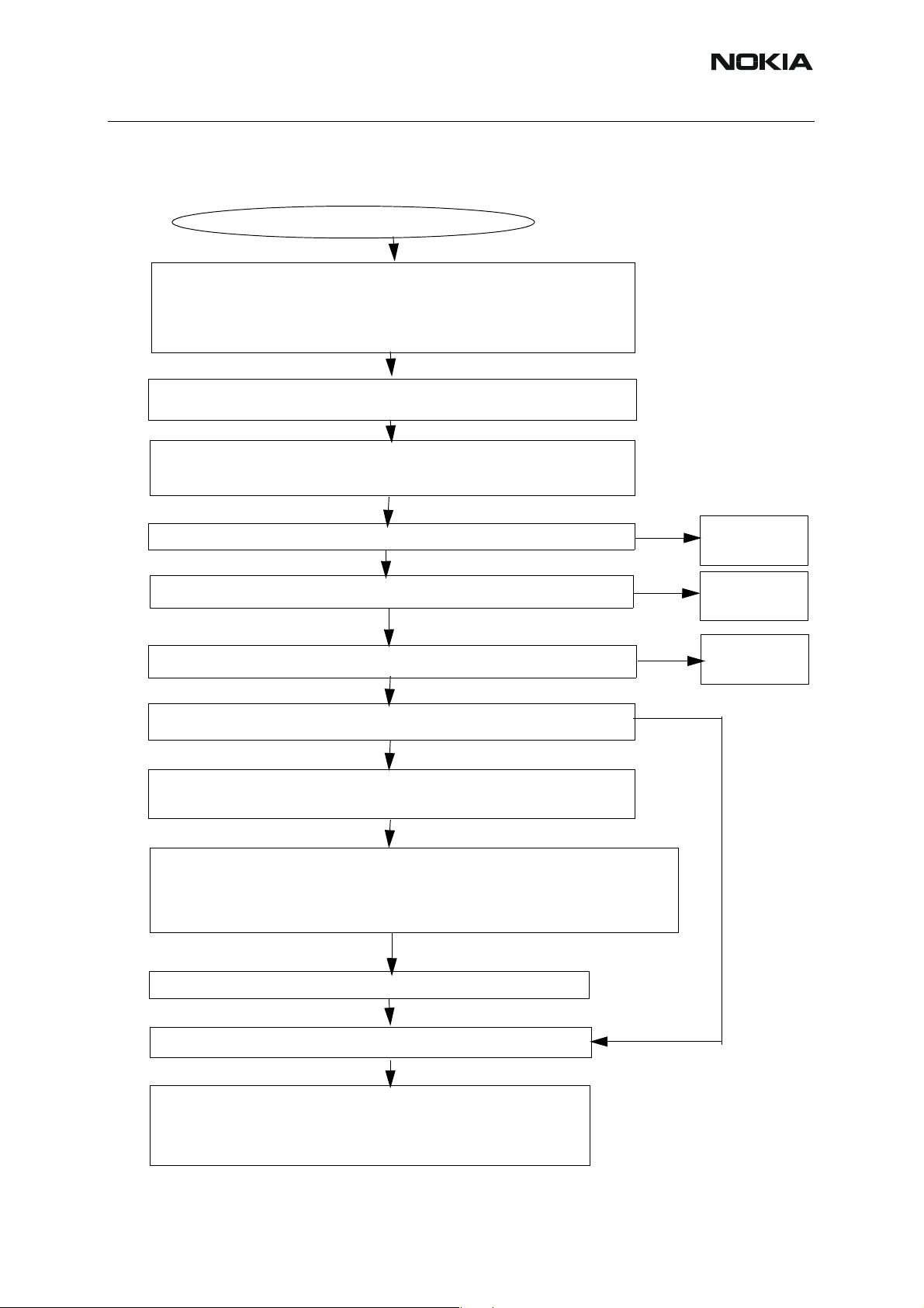
■ Synthesizer troubleshooting
Synthesizer Troubleshooting
Phoenix: RF local mode Rx continuous
Frequency = 3770.4 MHz @ ch. 38
Measure G501 VCTCXO output voltage at G501 pin 3
26 MHz 900 mVpp. OK ?
Measure N500 26 MHz reference output voltage at
L515 800 mVpp. OK?
Measure G501 VCTCXO AFC voltage at C540.
Measure RF frequency and level at T500.
Place the probe through the hole in the shield!
Correct frequency found?
NO
No frequency or wrong frequency ?
No frequency found within the 3-4 GHz span
YES
Measure VCO supply voltage at C560
C501
= 2.8 V OK ?
YES
C52
YES
Synthesizer is ok
Wrong frequencies found
YES
Measure VCO control voltage at C505.
Voltage = 4.8V?
NO
VCO does not work or
the control loop is open
C504
Replace VCO
Check C503, R501, R502,
Check R502, C503, C504
C504, C505
R501 and C502
8 COMPANY CONFIDENTIAL ISSUE 1 11/04
Copyright © 2004 Nokia. All Rights Reserved.
Page 9
RM-14
RF Troubleshooting and Manual Tuning Nokia Customer Care
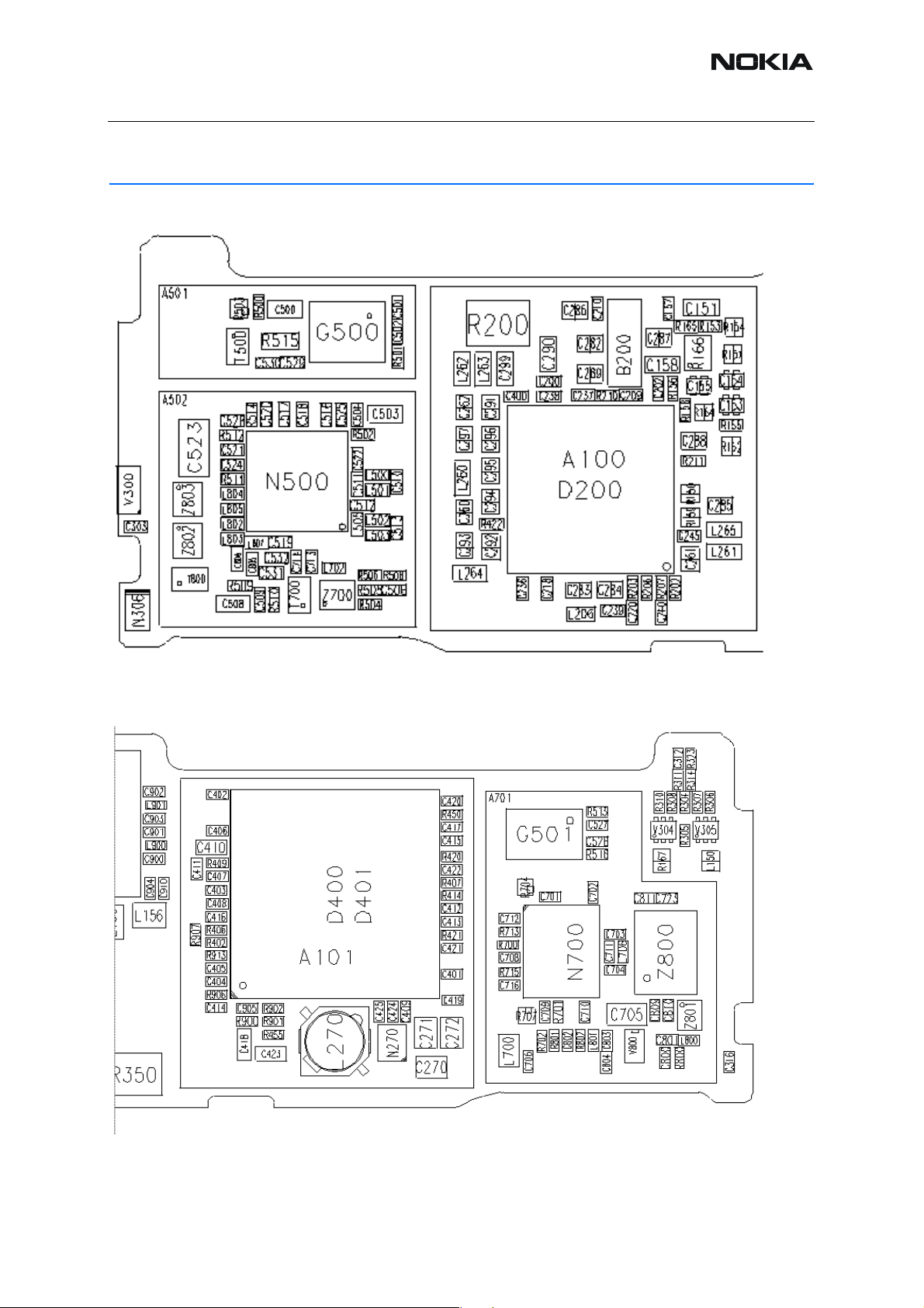
Tx Troubleshooting
Figure 3:Helgo/Synthesizer
Figure 4:PA/TX
ISSUE 1 11/04 COMPANY CONFIDENTIAL 9
Copyright © 2004 Nokia. All Rights Reserved.
Page 10
RM-14
TX850/900 GMSK t
Nokia Customer Care RF Troubleshooting and Manual Tuning
■ Tx 900 GMSK troubleshooting
Figure 5:TX 900 GMSK troubleshooting
TX 900 GMSK troubleshooting
Apply a 50 ohm load at the antenna connector of the jig.
GSM900/ cha. 37 = 897.4 MHz, burst mode power level 10
Spectrum analyzer: RBW = 500 Khz and VBW = 500 kHz,
center = 500 kHz and span = 20 MHz
Measure voltage of a) TXI at C529 and TXQ at C530,
Txi and TXQ = 500 mVpp min. and 1.4 VDC during burst
Measure a) TXC = 800 mV during burst at R514 and
b) TXP = 1.8 V during burst at J504 .
Note: TXC voltage is a function of power level
roubleshooting
Measure modulator supply voltage VR2 = 2.7 V (C511, both terminals)
Measure RF level = -13 dBm at input of Z700 SAW filter C702
Measure RF level = -13 dBm at N700 PA input (R704 pin1)
Measure RF level = +10 dBm at N700 PA output TX_OUT_EGSM
(Z800 pin1)
Measure N700 PA power detector DET = 850 mV during burst at R701.
Note: DET voltage is a function of power level
Measure N700 PA control voltage a) VPCTRL_G = 1.2 V during burst at
R713 and N700 PA bias voltage.
b) VTXB_G = 2.7V (C701).
Note: VPCTRL_G voltage is a function of power level.
NOK
NOK
NOK
NOK
OK
Check
baseband.
Check
N500 Helgo.
Check Z700
Tx SAW.
Measure N700 PA supply voltage VBAT at C705
Measure RF level = 20 dBm at antenna pad J124
Measure Z800 antenna switch control signal voltages
a) VANT_1 = 2.7 V at C811
b) VANT_2 = 0 V at C809
c) VANT_3 = 2.7 V at C810
10 COMPANY CONFIDENTIAL ISSUE 1 11/04
Copyright © 2004 Nokia. All Rights Reserved.
Page 11
RM-14
RF Troubleshooting and Manual Tuning Nokia Customer Care
■ Tx 1800/1900 GMSK troubleshooting
Figure 6:TX 1800/1900 GMSK troubleshooting
TX1800/1900 GMSK troubleshooting
Apply a 50 ohm load at the antenna connector of the jig.
GSM1800 ch. 700 = 1747,8 MHz, burst mode power level 5
GSM1900 ch. 661 = 1880,0 MHz, burst mode power level 5
Spectrum analyzer RBW = 500 kHz and VBW = 500 kHz
and span = 20 MHz
Measure voltage of a) TXI at C529 and TXQ at C530,
Txi and TXQ = 500 mVpp min. and 1.4 VDC during burst
Measure a) TXC = 800 mV during burst at R514 and
b) TXP = 1.8 V during burst at J504 .
Note: TXC voltage is a function of power level
Measure modulator supply voltage VR2 = 2.7 V at L505
Measure RF level = -15 dBm at input of T700 Tx balun C714
Measure RF level = -10 dBm at N700 PA input R707 pin1
Measure RF level = -3 dBm at N700 PA output TX_OUT_DCS (Z800)
NOK
Measure N700 PA power detector DET = 810 mV during burst at R701.
Note: DET voltage is a function of power level
Measure N700 PA control voltage a) VPCTRL_1800/1900 = 1.0 V during burst at R715
and N700 PA bias voltage
and N700 PA bias voltage
b) VTXB_1800/1900 = 2.7 V (C709).
Note: VPCTRL_1800/1900 voltage is a function of power level.
NOK
NOK
NOK
OK
Check
baseband.
Check
N500 Helgo.
Check T700
Tx balun.
Measure N700 PA supply voltage VBAT at C705
Measure RF level = 2 dBm at antenna pad J124
Measure Z800 antenna switch control signal voltages
a) VANT_1 = 0 V at C811
b) VANT_2 = 2.7 V at C809
c) VANT_3 = 2.7 V at C810
ISSUE 1 11/04 COMPANY CONFIDENTIAL 11
Copyright © 2004 Nokia. All Rights Reserved.
Page 12
RM-14
Nokia Customer Care RF Troubleshooting and Manual Tuning
Rx Troubleshooting
Figure 7:Helgo/Synthesizer
Figure 8:PA/TX
12 COMPANY CONFIDENTIAL ISSUE 1 11/04
Copyright © 2004 Nokia. All Rights Reserved.
Page 13
RM-14
RF Troubleshooting and Manual Tuning Nokia Customer Care
■ Rx 900 troubleshooting
Figure 9:RX 900 troubleshooting
RX 900 Troubleshooting
GSM900 ch. 37. Continuous Rx.
Use AGC “gain step” 14
Apply a signal of 942.46771 MHz (+67.71 kHz offset)
at -90 dBm to the antenna pad J124
Spectrum analyzer: RBW = 500 kHz, VBW = 500 kHz,
center = 942 MHz and span = 20 MHz
Measure voltage of a) RXI (J512) b) RXQ (J513). RXI and
RXQ = 800 mVpp and 1.35 VDC.
Note: DC level drops after a while.
Change the signal level to -30 dBm
OK
Measure RF level = -55 dBm at Z803 SAW filter input.
NOK
Measure Z800 antenna switch control signal voltages
a) VANT_1 = 0V (C811)
b) VANT_2 = 0V (C809)
c) VANT_3 = 0V (C810).
OK
Measure RF level = -55 dBm
at Helgo input (C808, both terminals).
NOK
go to
“Helgo/Synthesizer
troubleshooting”
OK
ISSUE 1 11/04 COMPANY CONFIDENTIAL 13
Copyright © 2004 Nokia. All Rights Reserved.
Page 14
RM-14
Nokia Customer Care RF Troubleshooting and Manual Tuning
■ Rx 1800 troubleshooting
Figure 10:RX 1800 troubleshooting
RX 1800 Troubleshooting
GSM1800 ch. 700. Continuous Rx.
Use AGC “gain step” 14
Apply a signal of 1842,86771 MHz (+67.71 kHz offset)
at -90 dBm to the antenna pad J124
Spectrum analyzer: RBW = 500 kHz, VBW = 500 kHz,
center = 1840 MHz and span = 20 MHz
Measure voltage of a) RXI (J512) b) RXQ (J513).
RXI and RXQ = 500 mVpp and 1.35 VDC.
Note: DC level drops after a while.
Change the signal level to -30 dBm
OK
Measure RF level = -30 dBm at Z802 SAW filter input.
(Z800 antenna switch pin11)
NOK
Measure Z809 antenna switch control signal voltages
a) VANT_1 = 0V (C811)
b) VANT_2 = 0V (C809)
c) VANT_3 = 0V (C810).
OK
Measure RF level
(C807, not assembled, both terminals).
at Helgo input
NOK
go to
“Helgo/Synthesizer
troubleshooting”
OK
14 COMPANY CONFIDENTIAL ISSUE 1 11/04
Copyright © 2004 Nokia. All Rights Reserved.
Page 15

RM-14
RF Troubleshooting and Manual Tuning Nokia Customer Care
■ Rx 1900 troubleshooting
Figure 11:RX 1900 troubleshooting
RX 1900 Troubleshooting
GSM1900 ch. 661. Continuous Rx.
Use AGC “gain step” 12.
Apply a signal of 1960,06771 MHz (+67.71 kHz offset)
at -90 dBm to the antenna pad J124.
Spectrum analyzer: RBW = 500 kHz, VBW = 500 kHz,
f = 1960 MHz and span = 20 MHz
Measure voltage of a) RXI (J512) b) RXQ (J513). RXI and
RXQ = 700 mVpp and 1.35 VDC.
OK
Change the signal level to -50 dBm and set “gain step” = 6
Measure RF level at Z801 SAW filter input.
(Z800 antenna switch pin1)
NOK
Measure antenna switch control signal voltages
a) VANT_1 = 0V (C811)
b) VANT_2 = 2.7V (C809)
c) VANT_3 = 2.7V (C810).
Measure RF level at V800 LNA input (C801).
Measure RF level at V800 LNA output (C804)
go to
“Helgo/Synthesizer
troubleshooting”
Measure a) V800 LNA supply voltage LNA_P = 2.8 V (V800 pin 4)
and b) LNA control voltage LNAB_P = 2,8 V (R801)
Measure RF level at N500 Helgo input (L807).
ISSUE 1 11/04 COMPANY CONFIDENTIAL 15
Copyright © 2004 Nokia. All Rights Reserved.
OK
Page 16

RM-14
Nokia Customer Care RF Troubleshooting and Manual Tuning
Bluetooth / FM Radio Troubleshooting
Figure 12:Bluetooth/FM
16 COMPANY CONFIDENTIAL ISSUE 1 11/04
Copyright © 2004 Nokia. All Rights Reserved.
Page 17

RM-14
RF Troubleshooting and Manual Tuning Nokia Customer Care
■ Bluetooth troubleshooting
Figure 13:Bluetooth troubleshooting
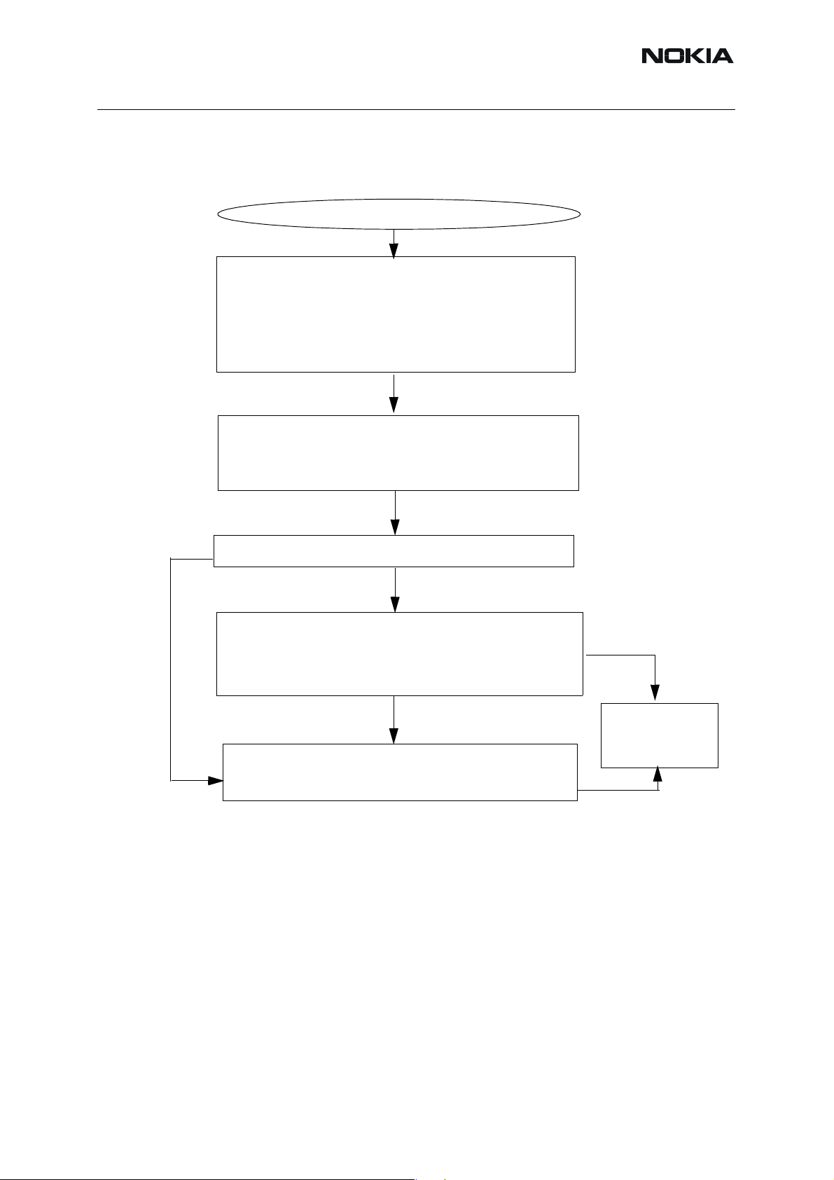
Bluetooth troubleshooting
Phoenix normal mode: Tx data 1 ch. 39 (2441 MHz approx. 1 MHz BW).
BC02 Bluetooth control. Options: Internal gain = 52
Spectrum analyzer: RBW = 500 kHz, VBW = 500 kHz,
center = 942 Mhz and span = 20 Mhz.
OK
Measure N130 BT supply voltage = 2.8V (C6036).
NOK
Replace N6031
OK
Measure N6030 VDD-ANA voltage regulator output = 1.8V (C6031)
OK
Measure a) N6030 VDD_VCO supply voltage = 1.8V (C6048)
b) VDD_MEM supply voltage = 1.8V
c) Rx/Tx supply voltage = 1.8V (C130)
OK
Measure SYSCLK voltage = 800 mVpp (26 MHz) 1.8 VDC (C6038).
OK
Measure N6030 XTAL_IN
voltage = 0.6Vpp square wave (R6042)
OK
Measure RF level = -15 dBm at a TX_A and TX_B,
(C6046) at both terminals
NOK
Measure D6030 supply voltage = 2,8V
at C6040
NOK
NOK
NOK
NOK
Check L6031, L6032. If passive components
OK, replace D6030.
Check L6031, L6032. If passive componen
OK, replace N6030
Replace N6030
Check L6033
Check L6033
and L130
and
and R6034
Check C6038 and go to
Synthesizer
troubleshooting.
NOK
OK
Measure RF level = -18 dBm at Z6030 SAW filter output.
NOK
ISSUE 1 11/04 COMPANY CONFIDENTIAL 17
Copyright © 2004 Nokia. All Rights Reserved.
Replace Z6030
Page 18

RM-14
Nokia Customer Care RF Troubleshooting and Manual Tuning
■ FM radio troubleshooting
Figure 14:FM radio troubleshooting
FM Radio Troubleshooting
Phoenix: Testing -> FM radio -> Power on.
FM signal: Frequency = 100 MHz, frequency deviation = 67.5 kHz, modulation fre-
quency = 1 kHz, R=L, pilot tone on and RF level -67 dBm. Signal is injected at X102
bottom connector pin 11, 12, 13 or 14.
Alternative: Use FM signal received by headset.
Measure audio voltage a) VAFL = 200 mVpp
(1 kHz) 850 mVDC (C6180, both sides
b) VAFR = 200mVpp (1 kHz) 850 mVDC
(C6182, both sides).
NOK
Measure CPOUT voltage = 0.9 V @ 100 MHz (C6162).
OK
Measure RF level at antenna input (C6176).
OK
NOK
NOK
FM Radio OK
Check 6158, R6159,
R6160, C6162
and C6157
Visual inspect C110, C111 and L1103
(all bottom side) and
C6179, C6176, C6178 and L6176
18 COMPANY CONFIDENTIAL ISSUE 1 11/04
Copyright © 2004 Nokia. All Rights Reserved.
Page 19

RM-14
RF Troubleshooting and Manual Tuning Nokia Customer Care
Service Tool Concept for RF Tunings
All RF tunings for RM-14 phones must be carried out in MJ-34 Module Jig.
Power to MJ-34 should be supplied from an external DC power supply, not
MJ-34 input voltages:
• Maximum + 16 VDC
• Nominal input for RF tunings is +12 V DC
Remember cable attenuation when setting required RF levels.
RF tunings should be made in the same order as shown in this document, the order of the cor-
responding menu items in the Phoenix Service SW may be different.
If baseband tunings are needed, they should be made before the RF tunings.
Avoid unnecessary tuning – factory tuning values are always the most accurate ones.
Views in this document may change as the service sof tware is developed. Please refer to the
Phoenix help files, phone model specific service manual and bulletins for help.
FPS-8 prommer.
ISSUE 1 11/04 COMPANY CONFIDENTIAL 19
Copyright © 2004 Nokia. All Rights Reserved.
Page 20

RM-14
Nokia Customer Care RF Troubleshooting and Manual Tuning
■ Service concept for RM-14 RF tunings
Table 1:
Item Type Description Product code
1 MJ-34 Module jig 0780346
2 PCS-1 DC power cable 0730012
3 XRF-1 Modular cable 0730085
4 DAU-9S Service MBUS cable 0730108
20 COMPANY CONFIDENTIAL ISSUE 1 11/04
Copyright © 2004 Nokia. All Rights Reserved.
Page 21

RM-14
RF Troubleshooting and Manual Tuning Nokia Customer Care
Receiver Tunings
■ RX channel select filter calibration
Extra equipment / external RF signal is not needed.
Must be done before other RX calibrations.
This function is used to calibrate RX channel select filter in GSM Phones.
Rx Channel select filter is tuned only in one (lowest) band = Single calibration for all bands.
Select Tuning => Rx Channel select filter calibration.
Press “Tune" to start the tuning.
Values will be saved to the phone when the “Save to Phone” tick box is checked.
If the “Save to Phone” tick box is not checked, the values are not saved to the phone when
you stop the tuning or exit the dialog.
Tuning values should be 0…31.
Select “Stop”.
Close the “RX Channel Select Filter Calibration“ dialog to end tuning.
ISSUE 1 11/04 COMPANY CONFIDENTIAL 21
Copyright © 2004 Nokia. All Rights Reserved.
Page 22

RM-14
Nokia Customer Care RF Troubleshooting and Manual Tuning
■ RX calibration
RF generator is needed.
This tuning performs RX Calibration.
Must be done separately on all bands
Calibration is automatically performed at EGSM (GSM900), then at GSM1800 and finally at the
GSM1900 band. If the tuning is successful, it continues in the next band.
AFC tuning is carried out while EGSM (GSM900) band RX Calibration is performed.
Remember to take jig and cable attenuations into account!
Select Tuning => Rx calibration
!
EGSM900 band
Press "Start" to begin.
22 COMPANY CONFIDENTIAL ISSUE 1 11/04
Copyright © 2004 Nokia. All Rights Reserved.
Page 23

RM-14
RF Troubleshooting and Manual Tuning Nokia Customer Care
Set RF generator to required EGSM900 frequency => OK
Tuning values and ADC readings will be shown
Typical values and limits in (GSM900) RX Calibration:
Table 2:
GSM900 Typical value Low limit High limit
AFC value 0 -350 350
AFC slope 150 50 350
RSSI 0 68 58 78
RSSI 1 74 64 84
RSSI 2 80 70 90
RSSI 3 86 76 96
RSSI 4 92 82 102
RSSI 5 97 87 107
RSSI 6 103 93 113
RSSI 7 109 99 119
RSSI 8 115 105 125
RSSI 9 121 111 131
RSSI 10 127 117 137
RSSI 11 133 123 143
RSSI 12 139 129 149
RSSI 13 145 135 155
RSSI 14 151 141 161
ISSUE 1 11/04 COMPANY CONFIDENTIAL 23
Copyright © 2004 Nokia. All Rights Reserved.
Page 24

RM-14
Nokia Customer Care RF Troubleshooting and Manual Tuning
Tuning will automatically move to the next band (GSM1800) when you press “Save & Contin-
ue”.
GSM1800 band
When asked, set the RF generator to required GSM1800 frequency => OK
Tuning values and ADC readings will be shown.
Typical values and limits in (GSM1800) RX Calibration:
Table 3:
GSM1800 Typical value Low limit High limit
RSSI 0 65 55 75
RSSI 1 71 61 81
RSSI 2 77 67 87
RSSI 3 83 73 93
RSSI 4 89 79 99
RSSI 5 94 84 104
RSSI 6 100 90 110
RSSI 7 106 96 116
RSSI 8 112 102 122
RSSI 9 118 108 128
RSSI 10 124 114 134
RSSI 11 130 120 140
RSSI 12 136 126 146
RSSI 13 142 132 152
RSSI 14 148 138 158
24 COMPANY CONFIDENTIAL ISSUE 1 11/04
Copyright © 2004 Nokia. All Rights Reserved.
Page 25

RM-14
RF Troubleshooting and Manual Tuning Nokia Customer Care
Tuning will automatically move to the next band (GSM1900) when you press “Save & Contin-
ue”
GSM1900 band
Set RF generator to required GSM1900 frequency => OK
Tuning values and ADC readings will be shown
Typical values and limits in (GSM1900) RX Calibration:
Table 4:
GSM1900 Typical value Low limit High limit
RSSI 0 67 57 77
RSSI 1 73 63 83
RSSI 2 79 69 89
RSSI 3 85 75 95
RSSI 4 91 81 101
RSSI 5 98 88 108
RSSI 6 104 94 114
RSSI 7 110 100 120
RSSI 8 116 106 126
RSSI 9 122 112 132
RSSI 10 128 118 138
RSSI 1 1 134 124 144
RSSI 12 140 130 150
RSSI 13 146 136 156
RSSI 14 152 142 162
ISSUE 1 11/04 COMPANY CONFIDENTIAL 25
Copyright © 2004 Nokia. All Rights Reserved.
Page 26

RM-14
Nokia Customer Care RF Troubleshooting and Manual Tuning
Tuning will be completed when you press “Save & Continue”.
Close the “RX – Calibration” dialog to end tuning.
■ RX band filter response compensation
RF generator needed.
Must be performed separately on all bands
Start the RX calibration at EGSM (GSM900), then continue to the GSM1800 band and finally
to the GSM1900 band.
Remember to carry out the RX calibration before carrying out Rx band filter response compen-
sation!
Remember to take jig and cable attenuations into account!
Select Tuning => Rx Band Filter Response Compensation
!
Select "Manual tuning" and “Start”.
You will be asked to supply 9 different RF frequencies to the phone on each band.
The tuning begins from EGSM900 band and continues the same way for GSM1800 and
GSM1900 bands.
26 COMPANY CONFIDENTIAL ISSUE 1 11/04
Copyright © 2004 Nokia. All Rights Reserved.
Page 27

RM-14
RF Troubleshooting and Manual Tuning Nokia Customer Care
EGSM900 band
Set first required frequency and level => OK
Set 2nd required frequency and level => OK
Set 3rd required frequency and level => OK
ISSUE 1 11/04 COMPANY CONFIDENTIAL 27
Copyright © 2004 Nokia. All Rights Reserved.
Page 28

RM-14
Nokia Customer Care RF Troubleshooting and Manual Tuning
Set 4th required frequency and level => OK
Set 5th required frequency and level => OK
Set 6th required frequency and level => OK
28 COMPANY CONFIDENTIAL ISSUE 1 11/04
Copyright © 2004 Nokia. All Rights Reserved.
Page 29

RM-14
RF Troubleshooting and Manual Tuning Nokia Customer Care
Set 7th required frequency and level => OK
Set 8th required frequency and level => OK
Set 9th required frequency and level => OK
Tuning values and ADC readings will be shown.
ISSUE 1 11/04 COMPANY CONFIDENTIAL 29
Copyright © 2004 Nokia. All Rights Reserved.
Page 30

RM-14
Nokia Customer Care RF Troubleshooting and Manual Tuning
Typical values and limits in Rx Band Filter Response Compensation EGSM900:
Table 5:
Channel
Input
frequency
[MHz]
Typical value
[dB]
Low limit
[dB]
High limit
[dB]
965 923.26771 +-3 -10 5
975 925.26771 +-1 -5 5
987 927.66771 +-1 -5 5
1009 932.06771 +-1 -5 5
37 942.46771 +-1 -5 5
90 953.06771 +-1 -5 5
114 957.86771 +-1 -5 5
124 959.86771 +-1 -5 5
136 962.26771 +-3 -10 5
Tuning will automatically move to the ne xt band (GSM1800) when you press “Save & Contin-
ue”.
GSM1800 band
Repeat the same steps as for the EGSM900 band above.
Typical values and limits in Rx Band Filter Response Compensation GSM1800:
Table 6:
Channel
Input
frequency
[MHz]
Typical value
[dB]
Low limit
[dB]
High limit
[dB]
497 1802.26771+-3 -10 5
512 1805.26771+-1 -5 5
535 1809.86771+-1 -5 5
606 1824.06771+-1 -5 5
700 1842.86771+-1 -5 5
791 1861.06771+-1 -5 5
30 COMPANY CONFIDENTIAL ISSUE 1 11/04
Copyright © 2004 Nokia. All Rights Reserved.
Page 31

RM-14
RF Troubleshooting and Manual Tuning Nokia Customer Care
Table 6:
870 1876.86771+-1 -5 5
885 1879.86771+-1 -5 5
908 1884.46771+-3 -10 5
Tuning will automatically move to the ne xt band (GSM1900) when you press “Save & Contin-
ue”.
GSM1900 band
Repeat the same steps as for the EGSM900 and GSM1800 bands above.
Typical values and limits in Rx Band Filter Response Compensation GSM1900:
Table 7:
Channel
Input
frequency
[MHz]
Typical value
[dB]
Low limit
[dB]
496 1927.06771+-3 -10 5
512 1930.26771+-1 -5 5
537 1935.26771+-1 -5 5
586 1945.06771+-1 -5 5
661 1960.06771+-1 -5 5
736 1975.06771+-1 -5 5
794 1986.66771+-1 -5 5
High limit
[dB]
810 1989.86771+-1 -5 5
835 1994.86771+-3 -10 5
ISSUE 1 11/04 COMPANY CONFIDENTIAL 31
Copyright © 2004 Nokia. All Rights Reserved.
Page 32

RM-14
Nokia Customer Care RF Troubleshooting and Manual Tuning
Tuning will be completed when you press “Save & Continue”.
Close the “RX Band Filter Response Compensation” dialog to end tuning.
32 COMPANY CONFIDENTIAL ISSUE 1 11/04
Copyright © 2004 Nokia. All Rights Reserved.
Page 33

RM-14
RF Troubleshooting and Manual Tuning Nokia Customer Care
Transmitter Tunings
■ TX power level tuning
Power Meter (or Spectrum analyzer) is needed.
With Tx power level tuning, the coefficients are adjusted for each power level.
Tuning must be performed separately on all band and all modes
When EDGE is on, the tuning must be carried out for all power levels.
Tx power level tuning steps are:
• EGSM900 PA High Mode with EDGE off
• EGSM900 PA High Mode with EDGE on
• GSM1800 PA High Mode with EDGE off
• GSM1800 PA High Mode with EDGE on
• GSM1900 PA High Mode with EDGE off
• GSM1900 PA High Mode with EDGE on
Select Tuning => Tx power level tuning
Remember to take jig and cable attenuations into account!
!
ISSUE 1 11/04 COMPANY CONFIDENTIAL 33
Copyright © 2004 Nokia. All Rights Reserved.
Page 34

RM-14
Nokia Customer Care RF Troubleshooting and Manual Tuning
EGSM900 PA High Mode with EDGE off
Select “Start”, the tuning begins automatically from the EGSM900 band.
Set Power Meter (or Spectrum analyzer) as required.
Note that TX PA mode is “High” at this point.
The coefficient table lists the power level, coef ficient, target dBm and DAC value for each power
level.
The tuned power level can be chosen by using up and down arrows or mouse.
The current power level is shown with inverse colors.
The tuning value can be adjusted with “-“ and “+” keys.
34 COMPANY CONFIDENTIAL ISSUE 1 11/04
Copyright © 2004 Nokia. All Rights Reserved.
Page 35

RM-14
RF Troubleshooting and Manual Tuning Nokia Customer Care
Tune base level and power levels 19,15 and 5 to target level.
When tuning values are correct, choose “Save & Continue”.
If all coefficients are within specified limit s, tuning will continue on the EGSM900 PA Low Mode
with EDGE off.
Typical values:
Table 8:
Power level GSM900 EDGE off
5 0.650 … 0.850
15 0.140 … 0.200
19 0.120 … 0.170
Base 0.090 … 0.130
EGSM900 PA high mode with EDGE on
Set Power Meter (or Spectrum analyzer) as required.
Repeat the same steps as for EGSM high and low mode above.
When EDGE is on, the tuning must be made for all power levels.
Tune base level
When tuning values are correct, choose “Save & Continue”.
If all coefficients are within specified limits, tuning will continue on th e EGSM900 PA low mode
with EDGE on.
ISSUE 1 11/04 COMPANY CONFIDENTIAL 35
and all power levels from 19 to 8 to target level.
Copyright © 2004 Nokia. All Rights Reserved.
Page 36

RM-14
Nokia Customer Care RF Troubleshooting and Manual Tuning
Typical values:
Table 9:
Power level GSM900 EDGE on
8 0.500 … 0.650
9 0.400 … 0.550
10 0.350 … 0.500
11 0.320 … 0.470
12 0.300 … 0.440
13 0.280 … 0.400
14 0.250 … 0.350
15 0.230 … 0.330
16 0.210 … 0.310
17 0.200 … 0.300
18 0.190 … 0.290
19 0.180 … 0.280
Base 0.100 … 0.180
GSM1800 PA high mode with EDGE off
Set Power Meter (or Spectrum analyzer) as required.
Repeat the same steps as for EGSM high and low mode above.
Tune base level
When tuning values are correct, choose “Save & Continue”.
If all coefficients are within specified limit s, tuning will continue on the GSM1800 PA high mode
with EDGE on.
Typical values:
and power levels 15,11 and 0 to target level.
Table 10:
Power level GSM1800 EDGE off
0 0.600 … 0.750
11 0.130 … 0.190
15 0.110 … 0.150
Base 0.090 … 0.130
36 COMPANY CONFIDENTIAL ISSUE 1 11/04
Copyright © 2004 Nokia. All Rights Reserved.
Page 37

RM-14
RF Troubleshooting and Manual Tuning Nokia Customer Care
GSM1800 PA high mode with EDGE on
Set Power Meter (or Spectrum analyzer) as required.
Repeat the same steps as for EGSM high and low mode above.
When EDGE is on, the tuning must be made for all power levels.
Tune base level
When tuning values are correct, choose “Save & Continue”.
If all coefficients are within specified limit s, tuning will continue on the GSM1900 PA high mode
with EDGE off.
Typical values:
and all power levels from 15 to 2 to target level.
Table 11:
Power level GSM1800 EDGE on
2 0.550 … 0.700
3 0.470 … 0.620
4 0.400 … 0.550
5 0.350 … 0.500
6 0.320 … 0.470
7 0.290 … 0.430
8 0.260 … 0.360
9 0.240 … 0.330
10 0.220 … 0.310
11 0.210 … 0.300
12 0.200 … 0.280
13 0.180 … 0.260
14 0.170 … 0.250
15 0.160 … 0.240
Base 0.090 … 0.160
ISSUE 1 11/04 COMPANY CONFIDENTIAL 37
Copyright © 2004 Nokia. All Rights Reserved.
Page 38

RM-14
Nokia Customer Care RF Troubleshooting and Manual Tuning
GSM1900 PA high mode with EDGE off
Set Power Meter (or Spectrum analyzer) as required.
Repeat the same steps as for EGSM high and low mode above.
Tune base level
When tuning values are correct, choose “Save & Continue”.
If all coefficients are within specified limit s, tuning will continue on the GSM1900 PA high mode
with EDGE on.
Typical values:
and power levels 15,11 and 0 to target level.
Table 12:
Power level GSM1900 EDGE off
0 0.600 … 0.750
11 0.130 … 0.190
15 0.110 … 0.150
Base 0.090 … 0.130
38 COMPANY CONFIDENTIAL ISSUE 1 11/04
Copyright © 2004 Nokia. All Rights Reserved.
Page 39

RM-14
RF Troubleshooting and Manual Tuning Nokia Customer Care
GSM1900 PA high mode with EDGE on
Set Power Meter (or Spectrum analyzer) as required.
Repeat the same steps as for EGSM high and low mode above.
When EDGE is on, the tuning must be made for all power levels.
Tune base level
When tuning values are correct, choose “Save & Continue”.
Typical values:
and all power levels from 15 to 2 to target level.
Table 13:
Power level GSM1900 EDGE on
2 0.550 … 0.700
3 0.470 … 0.620
4 0.400 … 0.550
5 0.350 … 0.500
6 0.320 … 0.470
7 0.290 … 0.430
8 0.260 … 0.360
9 0.240 … 0.330
10 0.220 … 0.310
11 0.210 … 0.300
12 0.200 … 0.280
13 0.180 … 0.260
14 0.170 … 0.250
15 0.160 … 0.240
Base 0.090 … 0.160
If values shown are within limits select “Save & Continue”, values are saved to phone memory .
Close the “TX Power Level Tuning” dialog to end tuning.
ISSUE 1 11/04 COMPANY CONFIDENTIAL 39
Copyright © 2004 Nokia. All Rights Reserved.
Page 40

RM-14
Nokia Customer Care RF Troubleshooting and Manual Tuning
■ TX I/Q tuning
Spectrum analyzer is needed.
Tx IQ tuning allows changing the Tx I DC Offset, Tx Q DC Offset, Amplitude difference and
Phase difference.
Must be performed separately on all bands
TX I/Q tuning steps are:
• EGSM (GSM900) with EDGE off
• EGSM with EDGE on
• GSM1800 with EDGE off
• GSM1800 with EDGE on
• GSM1900 with EDGE off
• GSM1900 with EDGE on
Remember to take jig and cable attenuations into account!
Select Tuning => TX IQ Tuning
!
EGSM900 band with EDGE Off
Select “Start” to begin tuning at EGSM900 band with EDGE off.
Set spectrum analyzer to required settings => OK
The tuning is carried out by setting each of the sliders to desired value. The sliders can be
changed only when the tuning is ongoing.
40 COMPANY CONFIDENTIAL ISSUE 1 11/04
Copyright © 2004 Nokia. All Rights Reserved.
Page 41

RM-14
RF Troubleshooting and Manual Tuning Nokia Customer Care
The order of tuning should be the same as the order of the sliders e.g. the Tx I DC Offset is
tuned first and Phase difference is tuned last.
Use <= , =>, PgUp or PgDn keys
The tuning is performed by setting each of the sliders to desired value.
Tune LO leak to minimum with TXI/TXQ DC of fset contro l (f0 on spectrum analyzer screen).
Tune the wrong sideband to minimum using Amplitude/Phase difference controls (f0+68kHz
on spectrum analyzer screen).
Table 14:
Before tuning After tuning
ISSUE 1 11/04 COMPANY CONFIDENTIAL 41
Copyright © 2004 Nokia. All Rights Reserved.
Page 42

RM-14
Nokia Customer Care RF Troubleshooting and Manual Tuning
Tx IQ Tuning limits are the same for all bands (GSM900, GSM1800 and GSM1900):
Table 15:
Tuning Limits EDGE off EDGE on
TX I DC Offset -4 … +4 -6 … +6
TX Q DC Offset -4 … +4 -6 … +6
Amplitude Difference -1.2 … +1.2 -1 … +1
Phase Difference 80 … 100 80 … 100
Tuning will automatically move to the next step, EGSM900 with EDGE on when you press
“Save & Continue”.
EGSM900 band with EDGE On
Choose “Start” to begin tuning.
Set the spectrum analyzer to required settings for EGSM900 band => OK
Repeat the same tuning steps as for the EGSM900 with EDGE off above.
Tuning will automatically move to the next step, EGSM1800 with EDGE off when you press
“Save & Continue”.
EGSM1800 band with EDGE Off
Choose “Start” to begin tuning.
Set the spectrum analyzer to required settings settings for GSM1800 band => OK
Repeat the same tuning steps as for the EGSM900 band above.
Tuning will automatically move to the next step, EGSM1800 with EDGE on when you press
“Save & Continue”.
GSM1800 band with EDGE On
Choose “Start” to begin tuning.
Set the spectrum analyzer to required settings for GSM1800 band => OK.
Repeat the same tuning steps as for the EGSM900 band above.
Tuning will automatically move to the next step, EGSM1900 with EDGE off when you press
“Save & Continue.
GSM1900 band with EDGE Off
Choose “Start” to begin tuning.
Set the spectrum analyzer to required settings for GSM1900 band=> OK.
Repeat the same tuning steps as for the EGSM900 band above.
Tuning will automatically move to the next step, EGSM1900 with EDGE on when you press
“Save & Continue”.
42 COMPANY CONFIDENTIAL ISSUE 1 11/04
Copyright © 2004 Nokia. All Rights Reserved.
Page 43

RM-14
RF Troubleshooting and Manual Tuning Nokia Customer Care
GSM1900 band with EDGE On
Choose “Start” to begin tuning.
Set the spectrum analyzer to required settings for GSM1900 band=> OK.
Repeat the same tuning steps as for the EGSM900 band above.
Tuning will be completed when you press “Save & Continue”.
Choose “OK” to close the “TX I/Q Tuning” dialog.
ISSUE 1 11/04 COMPANY CONFIDENTIAL 43
Copyright © 2004 Nokia. All Rights Reserved.
Page 44

RM-14
Nokia Customer Care RF Troubleshooting and Manual Tuning
[This page left intentionally blank]
44 COMPANY CONFIDENTIAL ISSUE 1 11/04
Copyright © 2004 Nokia. All Rights Reserved.
 Loading...