

Page 1

Nokia Customer Care
6(a) - Baseband
6(a) - Baseband Troubleshooting
and Manual Tuning
Troubleshooting
ISSUE 1 11/04 Copyright © 2004 Nokia. All Rights Reserved.
Page 2

RM-14
Nokia Customer Care Baseband Troubleshooting and Manual
Tuning
[This page left intentionally blank]
2 COMPANY CONFIDENTIAL ISSUE 1 11/04
Copyright © 2004 Nokia. All Rights Reserved.
Page 3

RM-14
Baseband Troubleshooting and Manual Tuning Nokia Customer Care
Table of Contents
Page No
Introduction .........................................................................................................5
General Failures.................................................................................................. 6
Phone is dead.................................................................................................... 6
Low battery operation time................................................................................. 8
Flash programming does not work..................................................................... 9
Charging failure................................................................................................ 10
Phone does not stay on, or phone is jammed.................................................. 11
Display information: “Contact Service”............................................................. 12
Function Failures ..............................................................................................14
Camera failure ................................................................................................. 14
Viewfinder working but no picture taken when pressing select-key ............... 16
FM-radio failure................................................................................................ 17
Infrared communication failure......................................................................... 18
SIM failure........................................................................................................ 19
Bluetooth failure............................................................................................... 20
Display failure .................................................................................................. 21
Audio failure..................................................................................................... 22
Uplink or downlink failure ...............................................................................22
Uplink missing audio signal ............................................................................23
Uplink weak audio signal ............................................................................... 24
Uplink distorted audio signal .......................................................................... 25
Uplink TDMA noise ........................................................................................26
Downlink missing audio signal .......................................................................27
Downlink weak audio signal ...........................................................................28
Downlink distorted audio signal ..................................................................... 29
Downlink noise in audio signal .......................................................................30
Downlink TDMA noise ....................................................................................31
Various noise problems ................................................................................. 32
BT audio errors ..............................................................................................33
Vibra errors ....................................................................................................34
Key failure........................................................................................................ 35
Power key failure ...........................................................................................35
UI module keys working .................................................................................36
Service Tool Concept for RM-14 Baseband Tunings..................................... 37
Service concept for RM-14 baseband tunings................................................. 38
Baseband Tunings ............................................................................................40
Energy management tuning............................................................................. 40
List of Figures
ISSUE 1 11/04 COMPANY CONFIDENTIAL 3
Copyright © 2004 Nokia. All Rights Reserved.
Page 4

RM-14
Nokia Customer Care Baseband Troubleshooting and Manual
Tuning
Page No
Fig 1 Phone is dead..............................................................................................8
Fig 2 Low battery................................................................................................... 9
Fig 3 Flash programming does not work............................................................... 10
Fig 4 Troubleshooting charging............................................................................. 11
Fig 5 Phone does not stay on, or is jammed......................................................... 12
Fig 6 Display information: “Contact Service”......................................................... 14
Fig 7 No picture..................................................................................................... 15
Fig 8 No picture 2.................................................................................................. 16
Fig 9 Viewfinder working but no picture taken when pressing select-key............. 17
Fig 10 Infrared communication failure................................................................... 19
Fig 11 SIM failure..................................................................................................20
Fig 12 Display failure............................................................................................. 22
Fig 13 Uplink or downlink failure ........................................................................... 23
Fig 14 Uplink missing audio signal........................................................................ 24
Fig 15 Uplink weak audio signal............................................................................ 25
Fig 16 Uplink distorted audio signal ......................................................................26
Fig 17 Uplink TDMA noise .................................................................................... 27
Fig 18 Downlink missing audio signal ...................................................................28
Fig 19 Downlink weak audio signal.......................................................................29
Fig 20 Downlink distorted audio signal.................................................................. 30
Fig 21 Downlink noise in audio signal...................................................................31
Fig 22 Downlink TDMA noise................................................................................ 32
Fig 23 Various noise problems.............................................................................. 33
Fig 24 BT audio errors ..........................................................................................34
Fig 25 Vibra errors ................................................................................................35
Fig 26 Power key failure........................................................................................36
Fig 27 UI module keys working.............................................................................37
4 COMPANY CONFIDENTIAL ISSUE 1 11/04
Copyright © 2004 Nokia. All Rights Reserved.
Page 5

RM-14
Baseband Troubleshooting and Manual Tuning Nokia Customer Care
Introduction
This document describes in overview the different hardware error possibilities for the RM-14
phone.
Not every possible hardware error is described in this document, but only those possible to correct.
Note! Most components are under shielding and therefore not changeable.
ISSUE 1 11/04 COMPANY CONFIDENTIAL 5
Copyright © 2004 Nokia. All Rights Reserved.
Page 6

RM-14
Nokia Customer Care Baseband Troubleshooting and Manual
Tuning
General Failures
■ Phone is dead
The phone doesn’t use any current at all when the supply is connected and/or power key is
pressed. It is assumed that the voltage supplied is 3,9Vdc. UEME will prevent any functionality
at battery/supply levels below 2,9Vdc and the software will shut the phone down at 3,1Vdc.
6 COMPANY CONFIDENTIAL ISSUE 1 11/04
Copyright © 2004 Nokia. All Rights Reserved.
Page 7

RM-14
Baseband Troubleshooting and Manual Tuning Nokia Customer Care
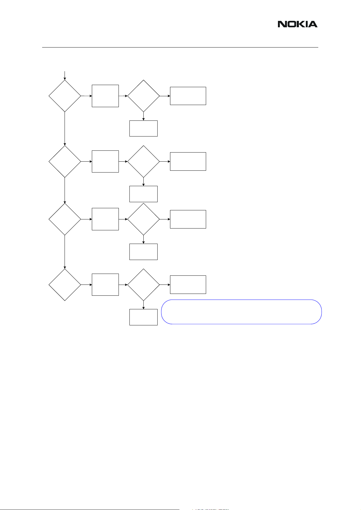
Figure 1:Phone is dead
Phone is dead
Yes
Phone shortcircuit DC
power
*)
Check RF-PA
Yes
No
Check SIM Switch
Ok
Check VBATT
on C104 ~3.9V
Measure voltages on both sides
No
of pin 12 of x1200 when power key
is pressed. Should be ~0V.
Yes
*)
Measure voltage on L260, L261, L262,
L263, L264, L265 and L206.
No
Should be ~3.9V.
No
*)
Sleep clock on J401:~32,768kHz, 1,8Vpp
*)
Measure voltage on PURX=1.8Vdc onJ404
or N6031 ~1sec after power key is pressed
*)
Yes
Yes
Measure voltage on VR3=2,78Vdc on C295pin1
.
*)
Yes
Verify that system clock is @~26MHz,
min 300mVACpp on C422 pin2 towards
D400(TIKU) with regular probe Cin ~10
-13pF/10M
Nok
Replace SIMgate
Check UI flex and PWB
*)
Failure in VBAT line:
Check X100, L260, L261, L262
L263, L264, L265, L206, C260
C261, C262, C283 and PWB
*)
No
Check B200, C209,C210,
D200 and PWB
No
*)
Check D200 and PWB
*)
No
Check D200, C295 and PWB
*)
No
Check C422, R420, N500 (Helgo),
G501 (26MHzXTAL) and PWB
*)
Yes
Note! The boxes marked with *)
are not serviceable parts.
Check D400 (TIKU) and D401
ISSUE 1 11/04 COMPANY CONFIDENTIAL 7
Copyright © 2004 Nokia. All Rights Reserved.
The boxes inside the blue lines
are not changeable or measurable!
Page 8

RM-14
Nokia Customer Care Baseband Troubleshooting and Manual
Tuning
■ Low battery operation time
Figure 2:Low battery
8 COMPANY CONFIDENTIAL ISSUE 1 11/04
Copyright © 2004 Nokia. All Rights Reserved.
Page 9

RM-14
1
Baseband Troubleshooting and Manual Tuning Nokia Customer Care
■ Flash programming does not work
The flash programming on RM-14 boards is possible via the pads on the PWB and through the
SIM slide.
In flash programming error cases the flash prommer (via Phoenix or Darium) can give some
information about the fault. The fault information messages could be:
• Phone doesn't set Flashbus TXD line high after VCC is switch on.
• External RAM test failed.
These errors are some of the most common errors and based on this, a fault finding diagram
for flash programming is shown below. Various errors can appear from the prommer when
flashing the phone - not all of them can be directly linked to the HW or phone.
Because of the use of uBGA components, it is not possible to verify on the dia gram, if there is
a short circuit in control and address/data lines on TIKUEDGE, NOR flash, NAND flash or
SDRAM.
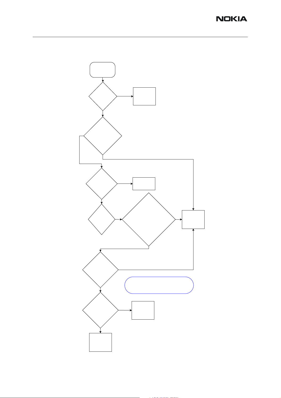
Figure 3:Flash programming does not work
*)
Re-solder \ Replace componet
)
*
Fix the connections if possible.
Else scarp the phone.
scrap
Note!
The boxes marked with *) are not serviceable parts!
Note!
The boxes inside the blue lines are not changeable
or measurable!
*)
No
Check SDRAM orientation and placement.
Placement OK ?
*)
No
Check PWB (if possible) and power lines.
Connecti ons OK ?
Flash programming does not work
*)
Prommer information is:
External RAM test failed. (C108)
Yes
Yes
*)
Flash again
Yes
Yes
*)
Replace the SDRAM
Prommer information is:
does
Phone dose not set Flashbus TXD line hi gh after VCC is switched on.
Yes
J39
Check J386 - resistor R397/R396
Connecti ons ok ?
*)
Try reading MCU ID with Phoenix
Reading OK ?
*)
Try reading flash ID with Phoenix
Reading OK ?
Yes
Yes
Yes
Flash again
No
Re-solder \ Replace componet
*)
No
Replace UEME or TIKU
*)
No
Replace NOR or NAND flash
ISSUE 1 11/04 COMPANY CONFIDENTIAL 9
Copyright © 2004 Nokia. All Rights Reserved.
Page 10

RM-14
Nokia Customer Care Baseband Troubleshooting and Manual
Tuning
■ Charging failure
Figure 4:Troubleshooting charging
Charging fails and no current
drawn from 'charger'
*)
Yes
Measure Vchar voltage on V101.
Is it > 3,0V?
Yes
Recalibrate charger circuitry and
retest. Did it work ?
Yes
END
Display information when charger
connected: "Not charging"
*) is SIM holder inserted?
NO
Check system connector
X101, F100, C121, V101, C102,
Swap the phone,
Check:
X1200
C103 and PWB
D200 (UEME) is faultyNO
C107
Yes
Recalibrate charger circuitry and
retest. Did it work ?
No
BTEMP=~68Ohm @roomtemperat-
Verify through Phoenix that BSI =
ure (~25)
~75kOhm (BL-5C) and BTEMP =
~47kOhm @ roomtemperature
(~25C)
Yes
Measure voltage on R200 towards
D200. Should be the same as
Vbat voltage
Yes
Phone should work. If not change
whole engine board
ENDYes
*)
No
Check:
BSI: Battery (BL-5C), C100, R203,
BSI: R102, C100, R203, Q104, pwb,
SIM SW, R203 and R206
BTEMP: R100, C101, R202, pwb
BTEMP:R100. C101, R202, pwb
and R207
Check:
pwb and R206
and R207
*)
No
Note!
The boxes marked with *) are not serviceable parts!
R200, D200 (UEME) and pwb
The boxes inside the blue lines
are not changeable or measurable!
Check:
10 COMPANY CONFIDENTIAL ISSUE 1 11/04
Copyright © 2004 Nokia. All Rights Reserved.
Page 11

RM-14
Baseband Troubleshooting and Manual Tuning Nokia Customer Care
■ Phone does not stay on, or phone is jammed
If the MCU doesn’t service the watchdog register within the UEME, the operations watchdog
will run out after approximately 32 seconds. It is not possible to measure this service routine.
Figure 5:Phone does not stay on, or is jammed
Phone does not stay on
or is jammed
Yes
Verify that system clock is @
~26MHz, min300mVaCpp on
C422 pin2 towards D400 (TIKU)
with regular probe Cin~10-13pF/
10M
Yes
Measure voltage on PURX=
1.8Vdc on N6031 ~1sec
after the power key is pressed.
Yes
UI functionality and keys
react to pressure
Yes
Can extraction of SIM holder
switch off the phone.
No
No
No
Check C422, R420, N500
(Helgo), G501 (26MHzXTAL)
and PWB.
Swap the phone
Check Z300,
UI board, keymat, lightguide,
and PWB.
Yes
Is everything working until
phone shuts down after ~32sec
No
Replace SIM
gate
ISSUE 1 11/04 COMPANY CONFIDENTIAL 11
No
Copyright © 2004 Nokia. All Rights Reserved.
Retest and if phone
still doesn’t work
change whole engine
board.
Yes
Swap the phone
Note!
The boxes inside the
blue lines are not
changeable or measurable!
Page 12

RM-14
Nokia Customer Care Baseband Troubleshooting and Manual
Tuning
■ Display information: “Contact Service”
When this error appears in the display it means that one or more of the internal baseband test s
has failed. The baseband tests (self tests) are performed each time the phone is powered on.
The self tests are divided into those performed while powering up (S t art up tests) and the ones
that can be executed with a PC using Phoenix (Runtime tests). The following S tart-up tests are
performed during power up:
UEM CBUS IF TEST
SLEEP X LOOP TEST
AUX DA LOOP TEST
EAR DATA LOOP TEST
TX IDP LOOP TEST
TX IQ DP LOOP TEST
SIM CLK LOOP TEST
SIM IO CTRL LOOP TEST
MBUS RX TX LOOP TEST
BACKUP BATT TEST
RADIO TEST
WARRANTY TEST
PA TEMP TEST
SIM LOCK TEST
PPM VALIDITY TEST
KEYBOARD STUCK TEST
LPRF IF TEST
FLASH CHECKSUM TEST
CAMERA IF TEST
EXT RAM DATA BUS TEST
EXT RAM ADDR BUS TEST
NAND FLASH ID TEST
BT WAKEUP TEST
IR IF_TEST
If all these self tests are passed, the phone will start up.
From Phoenix it’s possible to run all the self tests and the additional “Runtime test”. The test
cases can be seen below.
12 COMPANY CONFIDENTIAL ISSUE 1 11/04
Copyright © 2004 Nokia. All Rights Reserved.
Page 13

RM-14
Baseband Troubleshooting and Manual Tuning Nokia Customer Care
Figure 6:Display information: “Contact Service”
ISSUE 1 11/04 COMPANY CONFIDENTIAL 13
Copyright © 2004 Nokia. All Rights Reserved.
Page 14

RM-14
C
Nokia Customer Care Baseband Troubleshooting and Manual
Tuning
Function Failures
■ Camera failure
Figure 7:No picture
No picture
correctly?
present at
present at
*)
26 Mhz
present at
Module
placed
1.8V
L901
Z901?
2.7V
L901
Z900?
clock
R900?
Remove
No No
module
Yes
Check for
short circuit of
No No
C903, C902
or C291
Yes
Check for
short circuit of
No No
C901, C900
or C289
Yes
*)
Check for
No No
short circuit of
905
R900 or R904
Yes
Broken
springs etc.
X302
in X900?
Yes
X302
Change X900
Short
circuits?
Yes
Replace
component
Short
circuits?
Yes
Replace
component
Short
circuits?
Yes
Replace
component
Reposition module
UEME or PWB
FAILURE
UEME or PWB
FAILURE
PWB or TIKU
FAILURE
1.8V
present at
C904
Yes
Check for
No No
short circuit of
C904
Short
circuit?
Yes
Replace
component
PWB or TIKU
FAILURE
*) Most test points are not accessible unless
shielding cans are cut open. This must ONLY be done
by the Return Analysis technicians and for analysis only
Continue on
next page
14 COMPANY CONFIDENTIAL ISSUE 1 11/04
Copyright © 2004 Nokia. All Rights Reserved.
Page 15
RM-14
Baseband Troubleshooting and Manual Tuning Nokia Customer Care
Figure 8:No picture 2
*)
present at
*)
present at
*)
present at
Data
R913?
Clock
R906
Clock
R902?
*)
Check for
No No
short circuit of
R913
Yes
*)
Check for
No No
short circuit of
R906
Yes
*)
Check for
No No
short circuit of
R902
Yes
Short
circuits
Yes
Replace
component
Short
circuit?
Yes
Replace
component
Short
circuit?
Yes
Replace
component
CAMERA or PWB
FAILURE
CAMERA or PWB
FAILURE
TIKU or PWB
FAILURE
*)
Data
present at
R901?
*)
Check for
No No
short circuit of
R901
Short
circuit?
Yes
Replace
component
TIKU or PWB
FAILURE
*) Most test points are not accessible unless
shielding cans are cut open. This must ONLY be done
by the Return Analysis technicians and for analysis only
ISSUE 1 11/04 COMPANY CONFIDENTIAL 15
Copyright © 2004 Nokia. All Rights Reserved.
Page 16

RM-14
Nokia Customer Care Baseband Troubleshooting and Manual
Tuning
Viewfinder working but no picture taken when pressing select-key
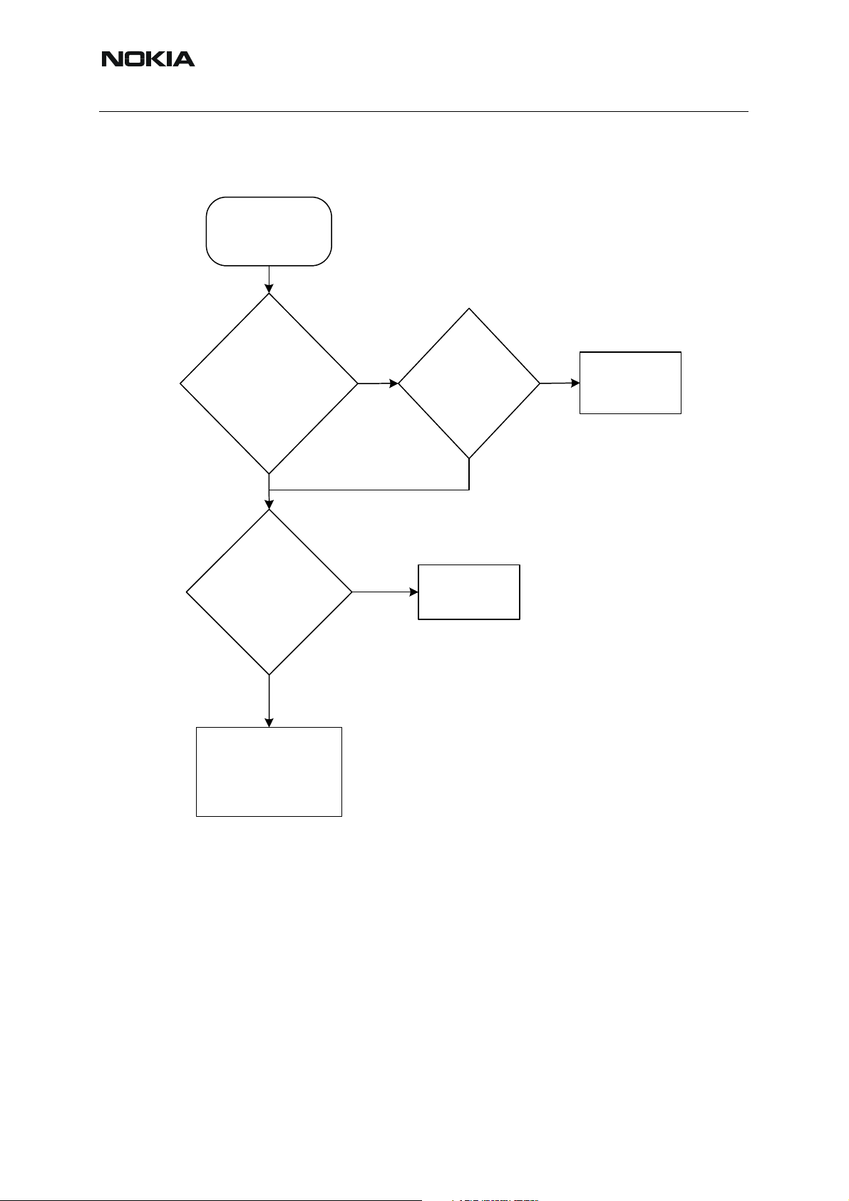
Figure 9:Viewfinder working but no picture taken when pressing select-key
Viewfinder working but no picture
taken when pressing select-key
Select key
functional?
Yes
*)
R906 = 104MHz
clock when
pressing select?
Reflash phone
Yes
No
Check
rotator flex and
keyboard with
Z300
Phoenix
Z300 and
X300 and
Flex OK?
X301 OK?
Yes
UI- or main
PWB
FAILURE
No
*)
No
Check for
short circuit of
R906
*) Most test points are not accessible unless
shielding cans are cut open. This must ONLY be done
by the Return Analysis technicians and for analysis only
Short
circuit?
Yes
Replace
component
No
Replace
component
CAMERA
FAILURE
16 COMPANY CONFIDENTIAL ISSUE 1 11/04
Copyright © 2004 Nokia. All Rights Reserved.
Page 17

RM-14
Baseband Troubleshooting and Manual Tuning Nokia Customer Care
■ FM-radio failure
The FM-radio troubleshooting guide is placed in the RF section.
ISSUE 1 11/04 COMPANY CONFIDENTIAL 17
Copyright © 2004 Nokia. All Rights Reserved.
Page 18

RM-14
Nokia Customer Care Baseband Troubleshooting and Manual
Tuning
■ Infrared communication failure
Figure 10:Infrared communication failure
IrDA Failure
Yes
Measure
VBAT at
C350 = 3,7-
4,2V ?
Yes
Measure
VFLASH1 at
C351=2,78V
Yes
Measure VIO
at
C352=1,80V
C353=1,80V
No
No
No
Defect PWB
Replace
Defect PWB
D200
Replace
Defect PWB
D200
Yes
Measure
activity TXD
on N350 pin3
?
Yes
Replace N350
18 COMPANY CONFIDENTIAL ISSUE 1 11/04
Copyright © 2004 Nokia. All Rights Reserved.
No
Replace
Defect PWB
D400
Page 19

RM-14
Baseband Troubleshooting and Manual Tuning Nokia Customer Care
■ SIM failure
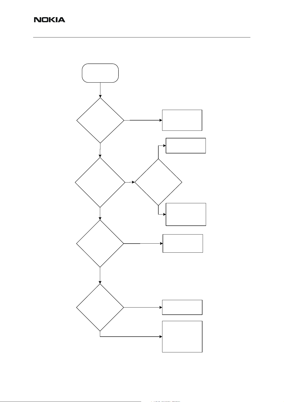
The hardware of the SIM interface from the UEME (D200) to the SIM connector (X386) can be
tested without a SIM card. When the power is switched on, the phone first checks for a 1,8V
SIM card and then a 3V SIM card. The phone will try this four times, whereafter it will display
"Insert SIM card".
The error ”SIM card rejected” means that the ATR message received from the SIM card is corrupted, e.g. data signal levels are wrong. The first data is always ATR and it is sent from card
to phone.
Figure 11:SIM failure
SIM Fault
Is used sim a
3,0V or 1,8V
card ?
Yes
Measure
VSIM at
X386. Is it 3V
or 1,8V?
Yes
Check SIM power-up
sequence
(picture of 3V sim card)
Should be as
No
Replace used
test sim-card
Check SIM
No No
reader X386
Is not as
picture
picture
Measure
VSIM at
C390. Is it
3V?
Yes
Replace R388
UEME FAILURE
VSIM
Reset
Clock
Data
ISSUE 1 11/04 COMPANY CONFIDENTIAL 19
Copyright © 2004 Nokia. All Rights Reserved.
Page 20

RM-14
Nokia Customer Care Baseband Troubleshooting and Manual
Tuning
■ Bluetooth failure
The Bluetooth troubleshooting guide is placed in the RF section.
20 COMPANY CONFIDENTIAL ISSUE 1 11/04
Copyright © 2004 Nokia. All Rights Reserved.
Page 21

RM-14
Baseband Troubleshooting and Manual Tuning Nokia Customer Care
■ Display failure
Figure 12:Display failure
Display fails
Yes
Is display working
Yes
NO
Yes
Change display
module
Is display
working?
NO
Measure Vflash1 @
L302 towards X302
(display connector).
Should be ~2,78Vdc
Yes
Measure VIO @ L301
towards X302 (display
connector). Should be
~1,8Vdc
Yes
Are LED's working?
Measure Vout on
C304 = ~13,5V
NO
NO
NO
*)
Check:
X302, C311, L302, C310,
D200 (UEME) and PWB
*)
Check:
X302, C309, L301, C308,
R307, D200 (UEME) and
PWB
Check:
N300, C304, R308, R312,
R306, X302, R305, X300, pwb
and UI board
End
Yes
Measure RESX on
X302 - pin 24. Should
be ~1,8V.
Yes
Phone should work. If
not change engine
board.
*)
NO
Check:
D400 (TIKU) and pwb
*) Some of the components
under shield, not changeable
or measurable parts.
ISSUE 1 11/04 COMPANY CONFIDENTIAL 21
Copyright © 2004 Nokia. All Rights Reserved.
Page 22

RM-14
Nokia Customer Care Baseband Troubleshooting and Manual
Tuning
■ Audio failure
Uplink or downlink failure
Figure 13:Uplink or downlink failure
Start
Is there an
audio
signal?
Yes
Is audio
level
sufficient?
Yes
Is audio
signal
undistorted?
Yes
Is TDMA
noise
inaudible
uplink
No
No
No
No
Go to "Uplink
missing audio
signal"
Go to "Uplink
weak audio
signal
Go to "Uplink
distorted
audio signal"
Go to "Uplink
TDMA noise"
Is problem
uplink or
downlink
Is there an
audio
signal?
Yes
Is audio
level
sufficient?
Yes
Is audio
signal
undistorted?
Yes
Is audio
signal free
of noise
downlink
No
No
No
No
Go to
"Downlink
audio signal
missing"
Go to
"Downlink
audio signal
weak"
Go to
"Downlink
audio signal
distorted"
Go to
"Downlink
audio signal
noise"
Yes
Is there no
acoustical
feedback
No
Go to
"Acoustical
feedback"
Yes
Is TDMA
noise
inaudible
Yes
Is there no
acoustical
feedback
Yes
Click noise, audio
signal too loud or
bad picture/
sound
synchronization
No
No
No
Go to
"Downlink
TDMA noise"
Go to
"Acoustical
feedback"
Software
error or bad
TIKU
22 COMPANY CONFIDENTIAL ISSUE 1 11/04
Copyright © 2004 Nokia. All Rights Reserved.
Page 23
RM-14
Baseband Troubleshooting and Manual Tuning Nokia Customer Care
Uplink missing audio signal
Figure 14:Uplink missing audio signal
Start
No
Is mute
deactivated?
Is problem
present both with
hand portable
and accessory?
Is problem
solved when
using
accessory?
Yes
Measure
mic. bias. Is
it close to
2.1 V ?
Yes
No
No
Deactive
mute in menu
Accessory is
defective
*)
Are any of the bias
No
components defective ?
(check R153, C151 and
R154
R151 for hand portable
and R156, C158, R166,
C159 and L152 for
*)
No
Replace
UEME
accessory)
Yes
Replace
defective parts.
Is bias close to
2.1 V ?
No
*) Some of the components
under shield, not changeable
Yes
Are microphone
contacts and
PWB pads ok ?
Yes
Replace
microphone
or measurable parts.
No
Clean
contacts and
pads
ISSUE 1 11/04 COMPANY CONFIDENTIAL 23
Copyright © 2004 Nokia. All Rights Reserved.
Page 24

RM-14
Nokia Customer Care Baseband Troubleshooting and Manual
Tuning
Uplink weak audio signal
Figure 15:Uplink weak audio signal
Start
Is
microphone
opening
clean?
Yes
Measure
bias. Is it
close to
2.1V?
Yes
No
No
*)
Clean
opening
Are any of the bias
components
defective (check
R153, C151 and
R154
R151)
Yes
Replace
defective parts.
Is bias close to
2.1 V
Yes
No
*)
Replace
UEME
No
Are microphone
contacts and
PWB pads ok?
Yes
*)
Are any of the
components L151,
R154, C154, C153,R155,
C165, R155, R162
or R157 missing or
R162 or R157 damaged
damaged?
or missing?
Replace
microphone
Clean contacts and pads. If
No
tracks are badly corroded it
may not be possible to
repair phone
*) Some of the components
under shield, not changeable
or measurable parts.
24 COMPANY CONFIDENTIAL ISSUE 1 11/04
Copyright © 2004 Nokia. All Rights Reserved.
Page 25

RM-14
Baseband Troubleshooting and Manual Tuning Nokia Customer Care
Uplink distorted audio signal
Figure 16:Uplink distorted audio signal
Start
Is there no
distortion when
using
accessory?
Yes
Measure
bias. Is it
close to
2.1V?
Yes
No
No
*)
Are any of the bias
defective (check
R153, C151 and
defective parts.
Is bias close to
Defect
accessory
components
R154
R151)
Replace
2.1 V
*)
No
Replace
UEME
No
Yes
Are microphone
contacts and
PWB pads ok
Yes
Replace
microphone
Clean contacts and pads. If
No
tracks are badly corroded it
may not be possible to
repair phone
*) Some of the components
under shield, not changeable
or measurable parts.
ISSUE 1 11/04 COMPANY CONFIDENTIAL 25
Copyright © 2004 Nokia. All Rights Reserved.
Page 26
RM-14
Nokia Customer Care Baseband Troubleshooting and Manual
Tuning
Uplink TDMA noise
Figure 17:Uplink TDMA noise
Start
Is there TDMA
noise both in hand
portable and when
using accessory?
Yes
Replace
microphone. Is
there still noise?
Yes
Check for loose,
missing or damaged
shielding cans
No
No
Is there only
noise in hand
portable
mode?
Yes
Defective
microphone
No
Defective
accessory
26 COMPANY CONFIDENTIAL ISSUE 1 11/04
Copyright © 2004 Nokia. All Rights Reserved.
Page 27

RM-14
Baseband Troubleshooting and Manual Tuning Nokia Customer Care
Downlink missing audio signal
Figure 18:Downlink missing audio signal
Start
Is problem present
both in hand
portable mode and
when using FM
radio/music player/
MIDI?
Yes
Is problem
present both in
earpiece, IHF
and with
accessory?
Yes
No
No
earpiece, IHF or
associated with
Is problem
related to
accessory?
Is problem
FM radio or
music player/
MIDI?
FM
radio
Is external
antenna
working?
Yes
No
IHF
Music
player/MIDI
Defective
music file
Accessory is
not detected
or is defective
FM module is
defective
IHF is defective.
Check IHF speaker
and connections.
Check L155, L156
and C162.
Check UEME.
Earpiec
e
Accessory
Earpiece is
defective. Check
IHF speaker and
connections. Check
L153 and C164.
L155, L156 and
Check UEME.
C162.
Check UEME.
Accessory is
defective
Software or
UEME is
defective
ISSUE 1 11/04 COMPANY CONFIDENTIAL 27
Copyright © 2004 Nokia. All Rights Reserved.
Page 28

RM-14
Nokia Customer Care Baseband Troubleshooting and Manual
Tuning
Downlink weak audio signal
Figure 19:Downlink weak audio signal
Start
Is problem
present both in
earpiece and
IHF?
Yes
No
Is problem
related to
earpiece or IHF?
Earpiec
e
Is IHF
opening
clogged?
No
IHF
Is IHF
opening
clogged?
Yes
Yes
IHF is defective.
Check UEME.
Clean
opening
Check IHF
speaker and
connections.
Clean
earpiece
opening
IHF
No
Earpiece is
defective. Check
earpiece speaker
and connections.
Check UEME.
Software or
UEME is
defective
28 COMPANY CONFIDENTIAL ISSUE 1 11/04
Copyright © 2004 Nokia. All Rights Reserved.
Page 29

RM-14
Baseband Troubleshooting and Manual Tuning Nokia Customer Care
Downlink distorted audio signal
Figure 20:Downlink distorted audio signal
Start
Is problem
present both in
earpiece and
IHF?
Yes
No
Is problem
related to
earpiece or IHF?
Earpiec
e
IHF
IHF is defective.
Check IHF
speaker and
connections.
Check UEME.
Earpiece is
defective. Check
earpiece speaker
and connections.
Check UEME.
Software error.
Bad music files.
Defective FM
module.
Defective UEME
ISSUE 1 11/04 COMPANY CONFIDENTIAL 29
Copyright © 2004 Nokia. All Rights Reserved.
Page 30
RM-14
Nokia Customer Care Baseband Troubleshooting and Manual
Tuning
Downlink noise in audio signal
Figure 21:Downlink noise in audio signal
Start
Is noise
electrical or
mechanical?
Electrical
Is noise
associated with
earpiece/IHF
(hand portable
mode)?
No
Is noise
associated with
FM tuner or with
Music Player?
Mechanical
Yes
Music Player
Loose speaker or
other component
inside telephone
No
Does error
occur both in
earpiece and
IHF?
Yes
Defective
speaker.
Software error.
Defective or badly
tuned antenna.
Bad music file
FM radio
Is noise
associated with
accessory?
Yes
No
Defective FM
module
Defective
accessory. Repair
or Replace
accessory
30 COMPANY CONFIDENTIAL ISSUE 1 11/04
Copyright © 2004 Nokia. All Rights Reserved.
Page 31

RM-14
Baseband Troubleshooting and Manual Tuning Nokia Customer Care
Downlink TDMA noise
Figure 22:Downlink TDMA noise
Start
Is there TDMA
noise both in hand
portable and when
using accessory?
Yes
Replace battery.
Is there still
noise?
Yes
No
No
Is there only
noise in hand
portable
mode?
Yes
Defective
battery.
Check for loose,
missing or damaged
shielding cans.
Mistuned antenna.
Missing/bad
components.
Check that problem is
not related to uplink
TDMA noise.
No
Defective
accessory
ISSUE 1 11/04 COMPANY CONFIDENTIAL 31
Copyright © 2004 Nokia. All Rights Reserved.
Page 32

RM-14
Nokia Customer Care Baseband Troubleshooting and Manual
Tuning
Various noise problems
Figure 23:Various noise problems
Start
Sound
level too
loud?
No
Click noise
No
Picture/sound
synchronisation
Yes
Yes
Yes
Software
error
Software
error
Bad TIKU
32 COMPANY CONFIDENTIAL ISSUE 1 11/04
Copyright © 2004 Nokia. All Rights Reserved.
Page 33

RM-14
Baseband Troubleshooting and Manual Tuning Nokia Customer Care
BT audio errors
Figure 24:BT audio errors
Start
Accessory
working?
Yes
Software
working?
Yes
Defective BT
module or antenna.
Defective TIKU
No
No
Replace or
repair
accessory
Flash with
new software
ISSUE 1 11/04 COMPANY CONFIDENTIAL 33
Copyright © 2004 Nokia. All Rights Reserved.
Page 34

RM-14
Nokia Customer Care Baseband Troubleshooting and Manual
Tuning
Vibra errors
Figure 25:Vibra errors
Start
Wrong setting or
software error.
Contact problem.
No
Is there any
vibration?
Yes
Mechanical problem
- counterweight is
blocked
Defective or missing
vibra.
Defective UEME.
Is there
sufficient
vibration?
Yes
Vibra is
constantly
switched
on?
No
Intermittent
vibration?
No
Acoustical
noise?
No
Yes
Yes
Software error
Contact problem.
Defective vibra.
Defective UEME.
Software error.
Defective UEME.
Short circuit.
Yes
Bad connection.
Defective vibra.
Defective vibra.
Mechanical problem
- counterweight hits
D-cover/PWB.
Loose parts in
phone.
34 COMPANY CONFIDENTIAL ISSUE 1 11/04
Copyright © 2004 Nokia. All Rights Reserved.
Page 35

RM-14
Baseband Troubleshooting and Manual Tuning Nokia Customer Care
■ Key failure
Power key failure
Figure 26:Power key failure
Keypad fault
Power key Ok
?
No
Measure voltage
Measure voltage
from S323. Is it
X300 pin12 from
high?
UI board. Is it high?.
Yes
Measure voltage
Measure voltage
from UI board when
from S323 when
pressed. Is it high?
pressed. Is it high?
No
No
Yes
Check
Check Z300
R302,C302,S323
and line. If Okay
UEME failure
Check UI board.
Check S323. Is it
Is it ok?
Okay?
No
Change UI board
Change S323Phone is jammed
Yes
Phone is dead
ISSUE 1 11/04 COMPANY CONFIDENTIAL 35
Copyright © 2004 Nokia. All Rights Reserved.
Page 36

RM-14
Nokia Customer Care Baseband Troubleshooting and Manual
Tuning
UI module keys working
Figure 27:UI module keys working
Try to change UI
UI-module
keys working
No
Try to change UI
PWB. Are the
Flex. Are the keys
keys working now
working now?
?
No
Z300
Check X300 & X301
(Soldering and spring
contacts). Is it okay?
Yes
When keypad is pressed, are
the LEDS lit?
Measure Row0-Row4,
UP, DOWN and SELECT
lines from X301. Are
voltage levels ~1,8 V?
No
Yes
No
Retest UI module
Change X300 and/
Change Z300
or X301
No
Yes
End
Illumination fault
Yes
Measure SleepX
signal (J403), when key i s
pressed. Is voltage level
~1,8 V?
Yes
When keypad is
pressed, are the
LED's lit?
No
Check lines Row0-Row4,
UP, DOWN,and SELECT
from X300.
If Ok, change Z300 and/or
Z301. If it still fails, change
TikuEdge
No
End
Illumination fault
36 COMPANY CONFIDENTIAL ISSUE 1 11/04
Copyright © 2004 Nokia. All Rights Reserved.
Page 37

RM-14
Baseband Troubleshooting and Manual Tuning Nokia Customer Care
Service Tool Concept for RM-14 Baseband Tunings
EM calibrations should be carried out in JBV-1 Docking Station equipped with DA-40 Docking
St a t ion Ad apter
Note: RF tunings must be carried out in MJ-12 module jig.
Power to JBV-1 should be supplied from an external DC power supply, not
JBV-1 input voltages:
• Maximum + 16 VDC
• Nominal input for RF tunings is +12 V DC
FPS-8 prommer
ISSUE 1 11/04 COMPANY CONFIDENTIAL 37
Copyright © 2004 Nokia. All Rights Reserved.
Page 38

RM-14
Nokia Customer Care Baseband Troubleshooting and Manual
Tuning
■ Service concept for RM-14 baseband tunings
Table 1:
Item Type Description Product code
1 JBV-1 Docking Station 0770298
2 DA-40 Docking station
adapter
4 CA-5S DC-DC cable 0730283
5 XRF-1 RF antenna cable 0730085
6 PCS-1 DC power cable 0730012
7 DAU-9S Service MBUS cable 0730108
8 PKD-1 Software protection
key
9 Phoenix service SW 8408031
38 COMPANY CONFIDENTIAL ISSUE 1 11/04
Copyright © 2004 Nokia. All Rights Reserved.
0780380
0750018
Page 39

RM-14
Baseband Troubleshooting and Manual Tuning Nokia Customer Care
Table 1:
Item Type Description Product code
9 CD-ROM Phoenix service SW 0774286
ISSUE 1 11/04 COMPANY CONFIDENTIAL 39
Copyright © 2004 Nokia. All Rights Reserved.
Page 40
RM-14
Nokia Customer Care Baseband Troubleshooting and Manual
Tuning
Baseband Tunings
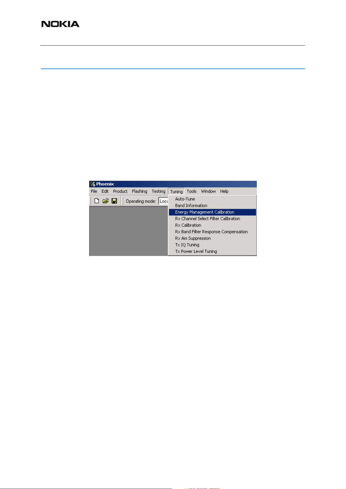
■ Energy management tuning
External power supply is needed.
EM Calibration is used for calibrating Battery and Charger settings of the phone.
Preparation for EM Calibration:
• Connect DC Cable CA-5S between JBV-1 and Vin of Phone for Charger calibration.
• Connect 12…15 V from Power Supply to JBV-1.
NOTE! Check that connection is F-BUS (doesn't work with M-BUS!).
Select Tuning => Energy Management Calibration
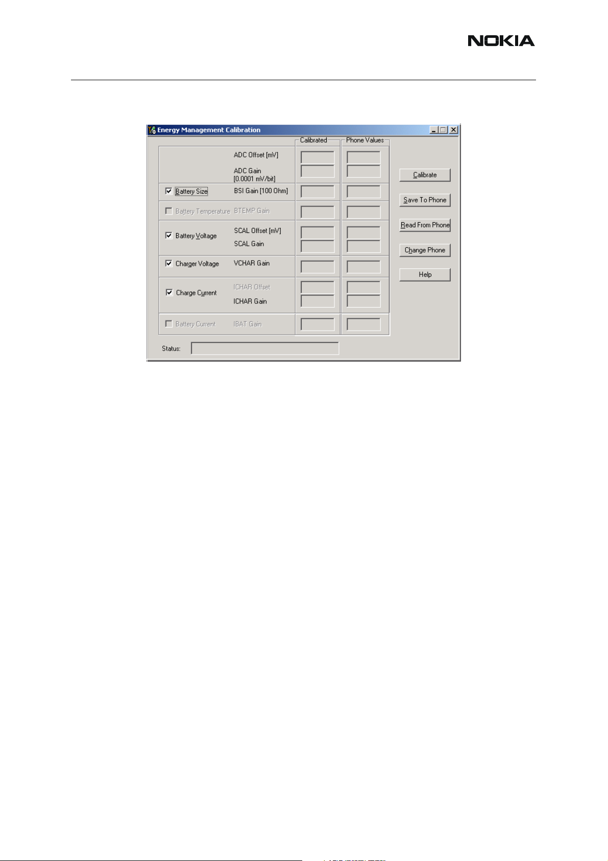
Energy Management values to be calibrated are checked.
Select “Read from Phone” to show current values in the phone memory and to check that the
communication with the phone works.
40 COMPANY CONFIDENTIAL ISSUE 1 11/04
Copyright © 2004 Nokia. All Rights Reserved.
Page 41
RM-14
Baseband Troubleshooting and Manual Tuning Nokia Customer Care
Select “Calibrate” to run selected calibrations.
Limits for Energy Management Calibration:
Min Max
ADC gain27000 28000
ADC offset-50 50
BSI gain930 1100
VBAT gain1000011000
VBAT offset24002600
VCHAR5800062000
ICHAR35004600
If values shown are within limits, select “Save To Phone” to save values to phone.
NOTE! Only values of checked tunings (Battery size, Battery T emperature etc…) will be saved.
Close the “Energy Management Calibration” dialog to end tuning.
ISSUE 1 11/04 COMPANY CONFIDENTIAL 41
Copyright © 2004 Nokia. All Rights Reserved.
Page 42

RM-14
Nokia Customer Care Baseband Troubleshooting and Manual
Tuning
[This page left intentionally blank]
42 COMPANY CONFIDENTIAL ISSUE 1 11/04
Copyright © 2004 Nokia. All Rights Reserved.
 Loading...