

Page 1

Nokia Customer Care
RM-8/RM-47/RM-48 Series Transceivers
5 - Disassembly Instructions
Issue 2 03/2005 Copyright „ 2005 Nokia Corporation. All rights reserved
Page 2

RM-8/RM-47/RM-48
Nokia Customer Care 5 - Disassembly Instructions
Table of Contents
Page No
Disassembly instructions of lower block ......................................................... 3
Disassembly instructions of upper block......................................................... 6
Domesheet exchange instructions ................................................................... 9
2 COMPANY CONFIDENTIAL Issue 2 03/2005
Copyright © 2004 Nokia. All Rights Reserved.
Page 3
RM-8/RM-47/RM-48
5 - Disassembly Instructions Nokia Customer Care
Disassembly instructions of lower block
Also see the video clips on care point.
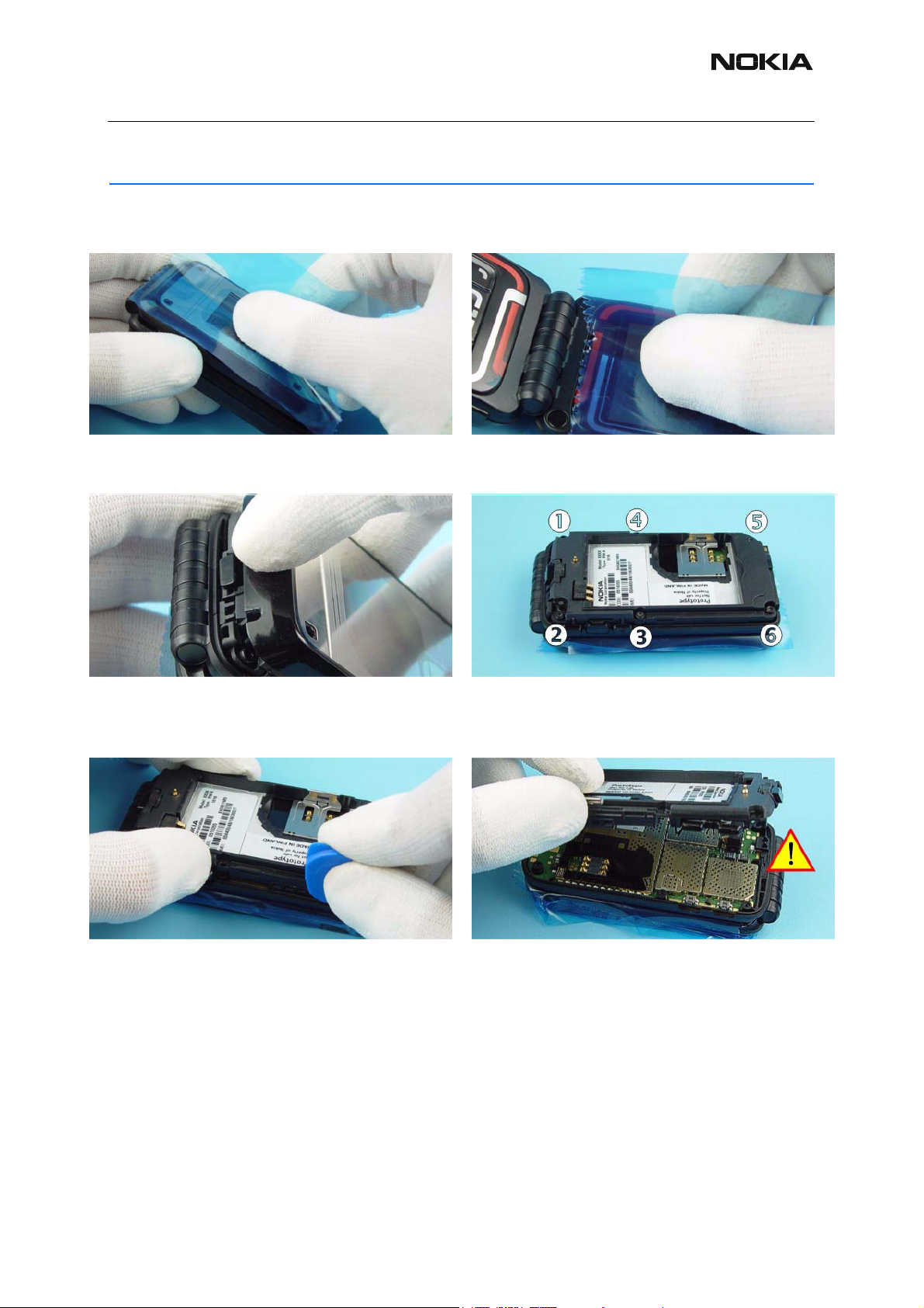
1.) Protect the window with a plastic film. 2.) Open the unit and protect the window
of the Inner LCD with a plastic film.
3.) Press the release button and remove the
B-Cover Lower Assy.
5.) Use the SRT-6 as a lever to open the snaps of the
C-Cover.
4.) Unscrew the six Torx Plus® size 6 screws of C-
Cover. For assembly, the reverse order and the
torque driver with a torque of 20Ncm has to be used.
6.) Remove the C-Cover Assy carefully. Note not to
damage the Power Button and the Function Key.
Issue 2 03/2005 COMPANY CONFIDENTIAL 3
Copyright © 2004 Nokia. All Rights Reserved.
Page 4

RM-8/RM-47/RM-48
Nokia Customer Care 5 - Disassembly Instructions
7.) Remove the DC-Jack with a DC plug. 8.) Use tweezers to pull up the Microphone.
9.) Use tweezers when removing the Vibra Motor. 10.) SRT-6 can be used to remove the A-Cover
Hinge Cap of Lower block.
11.) Open the coax connector of the Engine Module
carefully by using angled tweezers.
12.) Turn the Engine Module as shown in the picture. Use the C-Cover Assy as support for Engine
Module.
13.) Open the flex connector of the Engine Module
carefully by using SS-34.
4 COMPANY CONFIDENTIAL Issue 2 03/2005
Copyright © 2004 Nokia. All Rights Reserved.
14.) Remove the IRDA Window. Note the right
position when assembling.
Page 5

RM-8/RM-47/RM-48
5 - Disassembly Instructions Nokia Customer Care
15.) Remove the Keymat from the A-Cover Lower
carefully.
Issue 2 03/2005 COMPANY CONFIDENTIAL 5
Copyright © 2004 Nokia. All Rights Reserved.
Page 6

RM-8/RM-47/RM-48
Nokia Customer Care 5 - Disassembly Instructions
Disassembly instructions of upper block
Also see the video clips on care point.
15.) Pick up the Screw Head Caps with dental tool.
Always use new Caps when assembling.
17.) Place the SRT-6 between B-Cover and the A-
Cover Upper Block and shift it carefully along the
edge. Use it like a blade with moderate force to prevent damages at the covers.
16.) Unscrew the two Torx Plus® size 6 screws. For
assembly, the reverse order and the torque driver
with a torque of 20Ncm have to be used.
18.) The same procedure on the topside...
19.) ...and the same procedure on the other side. 20.) Now, the A-Cover can be pulled up.
6 COMPANY CONFIDENTIAL Issue 2 03/2005
Copyright © 2004 Nokia. All Rights Reserved.
Page 7

RM-8/RM-47/RM-48
5 - Disassembly Instructions Nokia Customer Care
21.) Fit protective film to the inner side of the window. 22.) Note to protect the Outer LCD with a film. Open
the Inner LCD connector by using the SS-34.
23.) Use tweezers when removing the A-Cover
Hinge Cap from Upper Block.
25.) Turn the UI-PWB as shown in the picture. 26.) First lift the Inner LCD with the SRT-6 and then
24.) Use SRT-6 to lift out UI-PWB.
remove it carefully.
27.) Protect Inner LCD with a film to avoid dust and
scratches.
Issue 2 03/2005 COMPANY CONFIDENTIAL 7
Copyright © 2004 Nokia. All Rights Reserved.
28.) Open the flex connector of the UI-PWB carefully
by using the SS-34.
Page 8

RM-8/RM-47/RM-48
Nokia Customer Care 5 - Disassembly Instructions
29.) Open the coax connector of the UI-PWB care-
fully by using tweezers.
30.) The Speaker is attached with an adhesive
Speaker Gasket to the A-Cover Upper Block. Use
the dental tool to remove the Speaker and be sure to
remove the remaining adhesive.
8 COMPANY CONFIDENTIAL Issue 2 03/2005
Copyright © 2004 Nokia. All Rights Reserved.
Page 9

RM-8/RM-47/RM-48
5 - Disassembly Instructions Nokia Customer Care
Domesheet exchange instructions
1.) Place the Engine Module into the Soldering Jig.
Use SRT-6 to lift a bit the Domesheet from Engine
Module. Always start on the shown side.
3.) Check the surface of the Engine Module for
remaining adhesive and clean it if necessary.
2.) Remove the defective Domesheet carefully. Note
not to damage the LEDs.
4.) Put the new Domesheet onto the Domesheet
Assembly Jig. Note the guide pins.
6.) Note the guide pins and the corresponding
5.) Use tweezers for support when removing the car-
rier foil.
Issue 2 03/2005 COMPANY CONFIDENTIAL 9
Copyright © 2004 Nokia. All Rights Reserved.
openings before to place the Engine Module on the
Jig.
Page 10

RM-8/RM-47/RM-48
Nokia Customer Care 5 - Disassembly Instructions
8.) Press on the Engine Module carefully and evenly.
7.) Place the Engine Module on the Jig as shown in the
picture.
9.) Lift the Engine Module with the new Domesheet
from the Jig.
10.) Check that the Domesheet is correctly stuck to the
Engine Module.
10 COMPANY CONFIDENTIAL Issue 2 03/2005
Copyright © 2004 Nokia. All Rights Reserved.
 Loading...