

Page 1

CCS Technica l Documentation
NSM-9DX Series Transceivers
Disassembly Instructions
Issue 1 10/02 ¤Nokia Corporation
Page 2

NSM-9DX
Disassembly Instructions CCS Technical Documentation
Table of Contents
Page No
Disassembling the NSM-9NX Transceiver.................................................................... 3
Page 2 ¤Nokia Corporation Issue 1 10/02
Page 3
NSM-9DX
CCS Technical Documentation Disassembly Instructions
Disassembling the NSM-9NX Transceiver
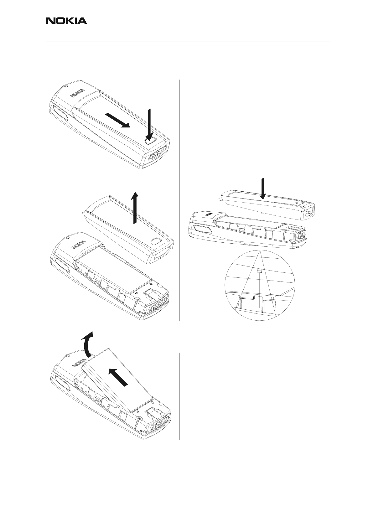
Remove Battery cover.
2
1
In assembly note!
3
1
Remove Battery.
2
Issue 1 10/02 ¤Nokia Corporation Page 3
Page 4

NSM-9DX
Disassembly Instructions CCS Technical Documentation
Remove A-cover.
Remove Keypad
(only if it is necessary to re
place keypad).
In assembly place A-cove
pins (4 pieces) in respecti
holes in the keypad.
Page 4 ¤Nokia Corporation Issue 1 10/02
Page 5

NSM-9DX
CCS Technical Documentation Disassembly Instructions
4.
Remove the 6 screws.
3.
2.
1.
5.
6.
Drive size is torx plus 6.
Tightening torque is 17 Ncm.
Fastening order in the picture
in disassembly.
In assembly check that PWB is not
bent.
Note! Screws contain thread lock
ing compound. Used screws must
be scrapped and not used again.
Note! Screws may be used a maximum of
four times before having to be scrapped
and not used again.
, and 1100rpm.
1
2
Remove UI module.
1. Use plastic tweezers or similar
tool to gently press the UI module
locking snap.
Note locking snaps when assem
bling UI.
2. Carefully lift up the UI module.
UI handling precautions!
Do not damage the following
items when handling the UI
module:
1. Speaker spring contacts.
2. LCD driver.
3. LCD contact pads.
4. UI PWB contact pads.
5. UI frame metal coating.
Issue 1 10/02 ¤Nokia Corporation Page 5
Page 6

NSM-9DX
Disassembly Instructions CCS Technical Documentation
1.
2.
3.
4.
5.
UI handling precautions!
1. Speaker spring contacts
2. LCD driver.
3. LCD contact pads.
4. UI PWB contact pads.
5. UI frame metal coating.
Remove speaker
(only if it is necessary to re
speaker).
Speaker can be lifted up u
straight-bladed screwdrive
shown in the picture.
Note! Do not touch speake
springs or membrane.
Page 6 ¤Nokia Corporation Issue 1 10/02
Page 7

NSM-9DX
CCS Technical Documentation Disassembly Instructions
Remove System Module
1.
2.
System Module handling pre
cautions!
Do not touch the following
spring contacts when handling
the module:
1. LCD connector.
2. Board to board connector.
Remove System connector
Note! Do not damage the spring
contacts in the System connector.
Issue 1 10/02 ¤Nokia Corporation Page 7
Page 8

NSM-9DX
Disassembly Instructions CCS Technical Documentation
Remove SIM cover
(only if it is necessary to replace SIM
cover).
1
1. Slightly lift the front edge of the
SIM cover to unlocked position
2. and slide it backwards.
2
4
3
3. Turn the SIM cover to upright
position.
4. Squeeze the SIM cover slightly
from the side to release the side
fixings one at the time.
5. Pull SIM cover out of B cover.
5
Page 8 ¤Nokia Corporation Issue 1 10/02
Page 9

NSM-9DX
CCS Technical Documentation Disassembly Instructions
NSM-9DX No power and A-cover fit
If a “No power” problem is found, please check the A-cover fit. Below are pictures of
good fit and bad fit. The engine needs to be fully fitt ed into the A-cover and the phone
will power up. The covers are changeable. The A-cover power button does not match up
with the engine power switch when the fit is not correct.
Figure 1: Good fit
Figure 2: Bad fit
Issue 1 10/02 ¤Nokia Corporation Page 9
Page 10

NSM-9DX
Disassembly Instructions CCS Technical Documentation
[ This page intentionally left blank. ]
Page 10 ¤Nokia Corporation Issue 1 10/02
 Loading...