

Page 1

CCS Technical Documentation
RH-25 Series Transceivers
Disassembly
Issue 1 10/2003 Confidential ©Nokia Corporation
Page 2
RH-25
Disassembly CCS Technical Documentation
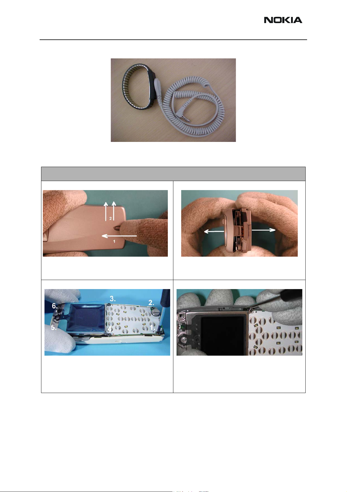
ESD Protection
Disassembly Instructions
Step-by-Step Disassembly Instructions (Model 6560)
Push the Release Button to the left before pulling up
the B-Cover. Remove the battery.
Unscrew the six T6 screws, using the shown order. For
assembly, the reverse order (i.e., labeled number 6 is first
screw for assembly) and a torque of 17Ncm must be
used.
Unlock the top guidance to remove the A-Cover.
As noted in the figure above, separate the two halves
from the side with connector while keeping the opposite side in place. This will cause less stress on the connector than removing perfectly straight.
Page 2 ©Nokia Corporation Confidential Issue 1 10/2003
Page 3

RH-25
CCS Technical Documentation Disassembly
Step-by-Step Disassembly Instructions (Model 6560)
Remove the modules from the C-cover and unplug the
display connector by pulling the modules apart carefully.
Open the snaps on both sides of display shield (two on
each side).
Microphone may be removed; however, it must be
replaced with a new part! When assembling new part,
pay special attention not to touch spring contacts as
they are easily damaged.
The Display Shield is hooked at the bottom edge.
Press the LCD off of the LCD Frame. Use a clean cloth
as shown above.
Bend the frame a bit, shift the UI Board Module to the
right and then pull it up.
Issue 1 10/2003 ©Nokia Corporation Confidential Page 3
Page 4

RH-25
Disassembly CCS Technical Documentation
Step-by-Step Disassembly Instructions (Model 6560)
To remove the DC Jack, insert tweezers between the
spring contacts and under the jack. You will need to
use some force to pull the jack upward.
Grip the Vibra Motor as shown above and pull it off of
its guidance.
Battery connector may be removed with a small pair of
needle nose pliers. Grasp connector between contacts
and pull straight up. If contacts are bent even slightly
during this procedure, replace with new part.
You can remove the infrared window with your fingers.
The Power Key must first be unlocked on the lower side
(see inset).
Unlock Antenna on both sides with a small screwdriver
or black stick.
The Antenna Pogo Pins can be removed by using the
torx driver to push them through the C-Cover.
Page 4 ©Nokia Corporation Confidential Issue 1 10/2003
Page 5

RH-25
CCS Technical Documentation Disassembly
Step-by-Step Disassembly Instructions (Model 6560)
The release button may be removed with fingers or
with black stick. Once removed, a new button must be
used as the retaining clips will have been weakened.
Assembly Instructions
Use the Disassembly Instructions in the reverse order to reassemble the handset.
Issue 1 10/2003 ©Nokia Corporation Confidential Page 5
Page 6

RH-25
Disassembly CCS Technical Documentation
Page 6 ©Nokia Corporation Confidential Issue 1 10/2003
 Loading...