

Page 1

CCS Technical Documentation
RH-25 Series Transceivers
Troubleshooting - RF
Issue 1 10/2003 Confidential ©Nokia Corporation
Page 2
RH-25
Troubleshooting - RF CCS Technical Documentation
Contents
Page No
Transceiver Troubleshooting ......................................................................................... 3
Receiver Troubleshooting ............................................................................................3
General instructions for RX troubleshooting............................................................ 3
Path of the received signal ........................................................................................ 3
Fault finding charts for receiver chain ...................................................................... 4
Transmitter Troubleshooting .......................................................................................9
General instructions for TX troubleshooting ............................................................ 9
Path of the transmitted signall................................................................................... 9
Fault finding charts for the transmitter.................................................................... 10
Synthesizer Troubleshooting .....................................................................................16
19.44 MHz reference oscillator............................................................................... 16
RX VHF .................................................................................................................. 17
TX VHF................................................................................................................... 17
UHF Synthesizer..................................................................................................... 18
Page 2 ©Nokia Corporation Confidential Issue 1 10/2003
Page 3

RH-25
CCS Technical Documentation Troubleshooting - RF
Transceiver Troubleshooting
The first thing to do when you are encountered with a problem is to carry out a thorough
visual check of the module. Make sure that:
• there are no mechanical damages
• the solder joints are OK
Note: Before changing anything, ALL SUPPLY VOLTAGES AND THE SYSTEM
CLOCK / SLEEP CLOCK should be checked.
Receiver Troubleshooting
General instructions for RX troubleshooting
Start the Phoenix software and use it to start the required RX-mode of the mobile phone.
The troubleshooting flowchart is divided into three steps: (1) general checking, (2) local
checking and (3) RX-chain checking.
Note: Before changing ASICs or Filters, all solderings and missing components must
be checked visually. After any possible component changes, the phone must be
tuned with the Phoenix autotune SW.
Path of the received signal
Block level description of the receiver:
(Antenna/ext RF) – Diplexer – Duplexer – Low Noise Amplifier (LNA) – RX band filter –
First mixer – 135.54 MHz RX IF filter – IF-amplifier – second mixer – 14 kHz low-pass filter – adjustable IQ amplifier – Baseband.
Issue 1 10/2003 ©Nokia Corporation Confidential Page 3
Page 4
RH-25
Troubleshooting - RF CCS Technical Documentation
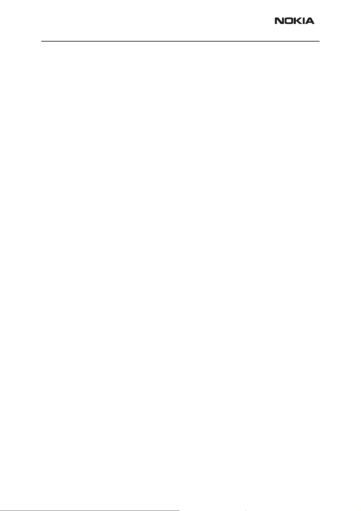
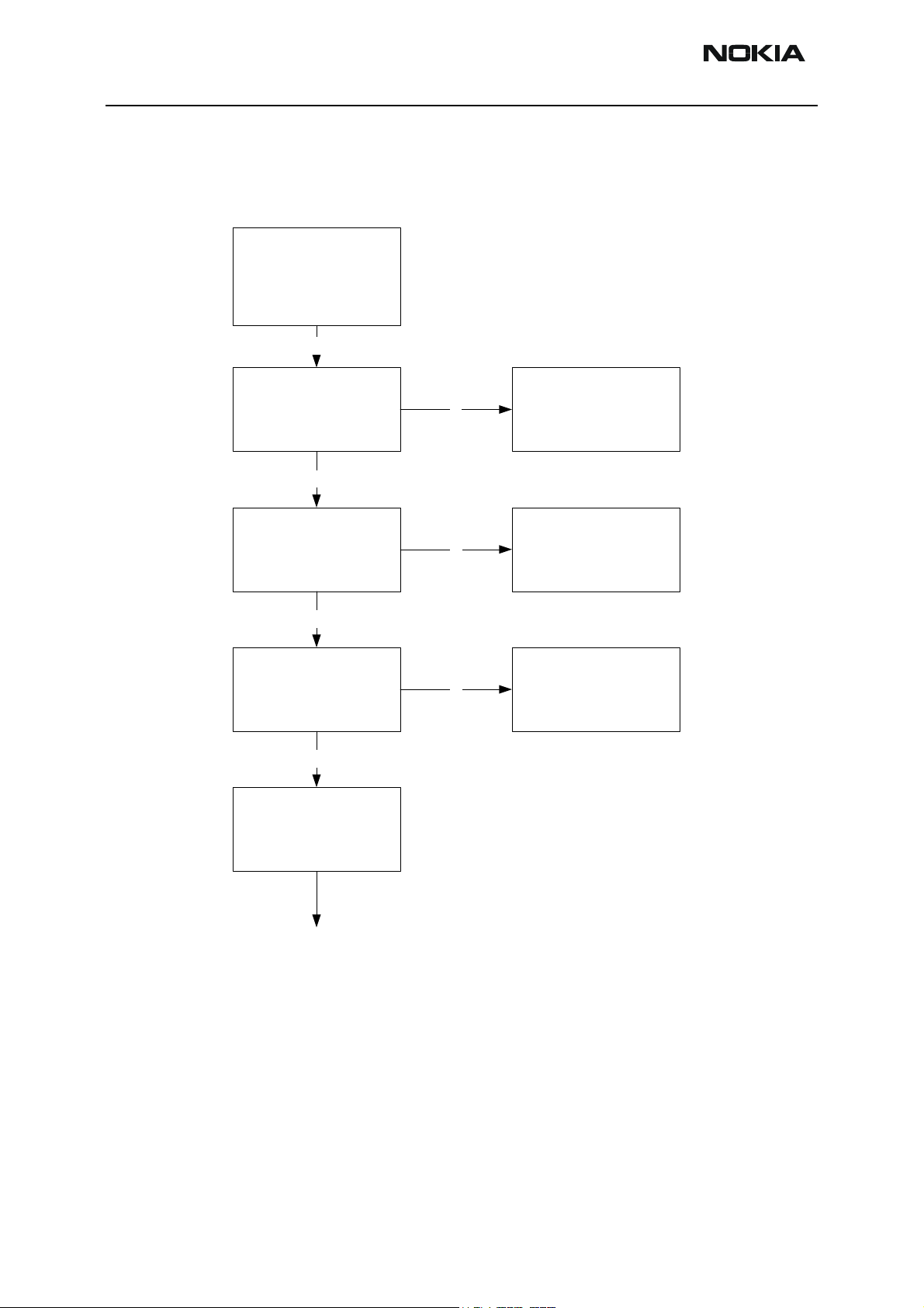
Fault finding charts for receiver chain
AMPS
Apply 881.49MHz = ch
383 -116dBm, 8kHz
dev, 1kHz sine to
external RF connector
(X900)
Y
Connect HS to cellular
tester, open AF: 1kHz
sine meas SINAD
AF:>12dB
N
Y
AMPS RX chain OK
Check UHF Vc (from
C773) V: 1.8 ... 2.1V
Y
Check RXVHF Vc
(from C720)
V: 0.7 ... 1.3
Y
Apply 881.49MHz
-30dBm, sine signal
external RF connector
(X900)
N
N
Start troubleshooting
Start troubleshooting
Page 4 ©Nokia Corporation Confidential Issue 1 10/2003
Page 5
RH-25
CCS Technical Documentation Troubleshooting - RF
Check input level at
diplexer (Z907)
Y
Check input level at
duplex filter
Y
Check input level at
LNA input
Y
Check RF level at
RX800 band filter
input
N
Change EXT RF
connector
soldering and
components in
antenna circuit
before changing.
NOTE: Check all
NOTE: Check all
N
Change diplexer
(Z907)
soldering and
discrete
components of
front end.
N
Change duplex filter
(Z906)
NOTE: Check all
solderings and
N
Change TACO (N801)
discrete components
around TACO before
changing.
Y
Check RF level at
MIX1Ain P/N
Y
N
Change TACO (N801)
Issue 1 10/2003 ©Nokia Corporation Confidential Page 5
Page 6
RH-25
Troubleshooting - RF CCS Technical Documentation
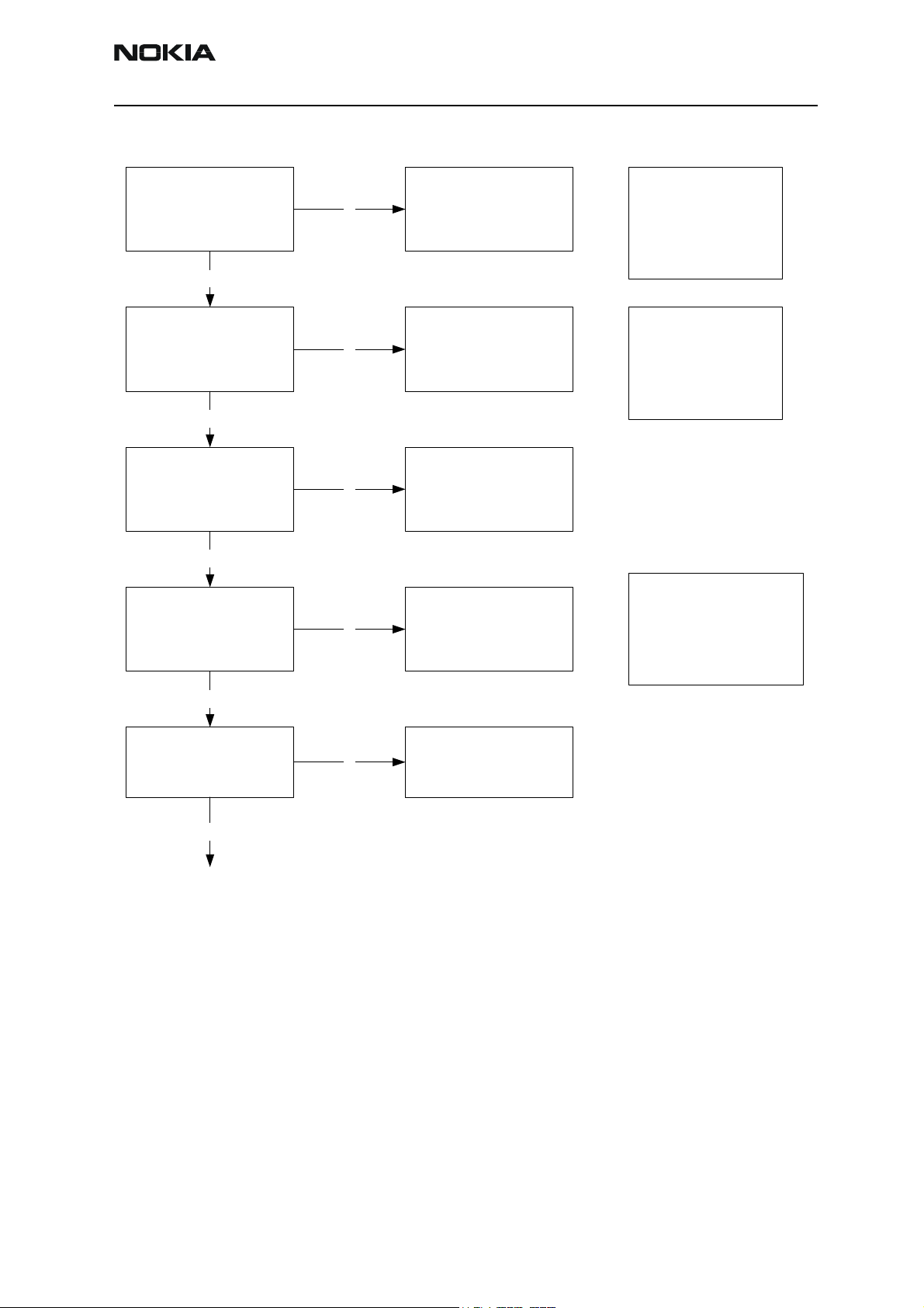
Check RF level at RX
IF filter input at
135.54MHz
Check RF level at RX
IF filter output at
135.54MHz
Y
Check RX I and Q
signals at I: J801(+),
J803(-) and Q:
J804(+), J802(-)
Check RF level at
N N
J751 and J752 at
2034.06MHz
Y
Change TACO (N801)
N
Change RX IF filter
(Z830)
Check RF level by
N
L730 without having
electrical contact at
271.08MHz
Start synthesizer
troubleshooting
NOTE: Check all
discrete
components and
voltages around
TACO.
N
Start synthesizer
troubleshooting
Y
Check UEM and start
baseband
troubleshooting
Y
Change TACO (N801)
Page 6 ©Nokia Corporation Confidential Issue 1 10/2003
Page 7

RH-25
CCS Technical Documentation Troubleshooting - RF
TDMA800
Since the same physical signal path is used for both analog and digital modes at the
lower band, there is no need for additional troubleshooting in the digital mode. So if the
digital mode at the lower band is not working properly, start the analog mode troubleshooting.
TDMA1900 (only dualband)
Only EXT RF connector –> 1
st
IF needs separate troubleshoot at upper band. After down
conversion (RF –> 135.54 MHz) both lower and upper band use same signal path.
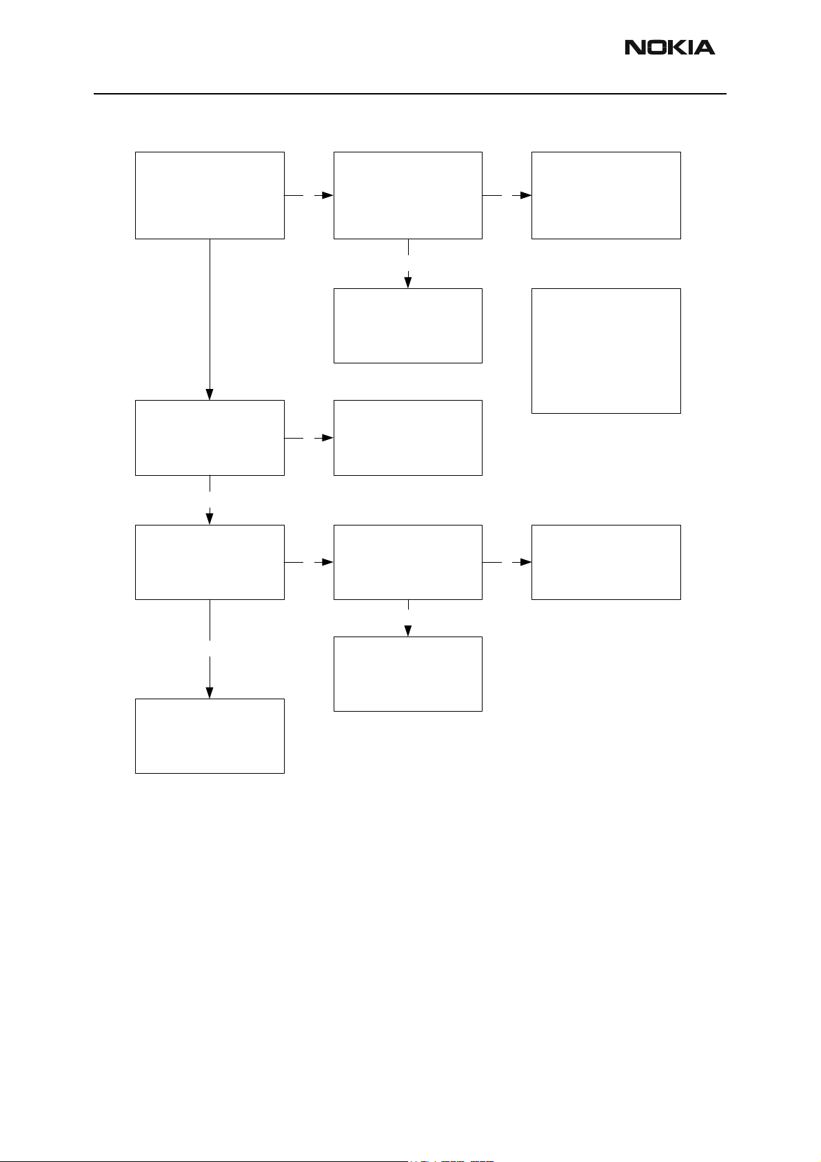
Apply 1960.02MHz =
ch1000 - 50 dBm
signal to external RF
connector (X900)
Y
Check RX I and Q
signals at I: J801(+),
J803(-), and Q:
J804(+), J802(-)
N
Check UHF Vc (from
C773) V: 2.2 ... 2.6V
TDMA1900 RX chain
Y
N
Start synthesizer
troubleshooting
is OK
Y
Check RXVHF Vc
(from C720).
V: 0.7 ... 1.3
Y
N
Start synthesizer
troubleshooting
Issue 1 10/2003 ©Nokia Corporation Confidential Page 7
Page 8

RH-25
Troubleshooting - RF CCS Technical Documentation
Check input level of
diplexer (Z907)
Y
Check input level of
duplex filter
Y
Check RF level at
LNA input (at duplex
filter RX output port)
Y
N
Change EXT RF
connector
soldering and
components in
antenna circuit
before changing.
NOTE: Check all
NOTE: Check all
N
Change diplexer
(Z907)
soldering and
discrete
components of front
end.
NOTE: Before
N
Change duplex filter
(Z962)
replacing TACO,
check all the
solderings and
components around
V850.
Check RF level at
RX1900 band filter
(Z850) input
Y
Check voltage at
N
C854 out (V850 in).
Change TACO (N801)
V: about 2.7V
Page 8 ©Nokia Corporation Confidential Issue 1 10/2003
Page 9

RH-25
CCS Technical Documentation Troubleshooting - RF
Y
Check RF level at
MIX1_B input
Y
Check RF level at RX
IF filter input at
135.54MHz
Y
Continue
troubleshooting like
LB
N
N
Transmitter Troubleshooting
Change RX1900 band
filter
Check RF level at
J751 and J752 at
2095.56MHz
Y
Change TACO (N801)
N
Start synthesizer
troubleshooting
NOTE: Check all
discrete
components and
voltages around
TACO
General instructions for TX troubleshooting
Always use an RF cable connected from an external RF connector to the analyzer via (rfpower) attenuator. This is important to protect the analyzer against excessive RF power
and not to allow leakage of undesired RF power into the cellular frequencies.
1 Start the Phoenix-software and select the TX mode under Testing (AMPS, DAMPS,
or TDMA 1900).
2 It is useful to select the mid channel (383 for AMPS/DAMPS or TDMA 1900) and
power level 2.
Note: After any component change, tune the phone with the Phoenix autotune SW.
Path of the transmitted signal
l
AMPS/DAMPS
UEM TX I/Q DA-converters -> I/Q modulator and Digital gain step amplifier (TACO) -> IFBPF -> Upconverter+driver (TACO) -> Balun->BPF -> PA -> Coupler (Power detector) ->
Duplex-filter -> Diplexer -> EXT RF-connector -> Antenna
Issue 1 10/2003 ©Nokia Corporation Confidential Page 9
Page 10

RH-25
Troubleshooting - RF CCS Technical Documentation
TDMA1900 (ONLY DUALBAND)
UEM TX I/Q DA-converters -> I/Q modulator and Digital gain step amplifier (TACO) -> IFBPF -> Upconverter+driver (TACO) -> Balun->BPF -> PA -> Coupler (Power detector) ->
Duplex-filter -> Diplexer -> EXT RF-connector -> Antenna
Fault finding charts for the transmitter
AMPS
1 Start the Phoenix software and set the phone to analog mode by using RF Test UI.
2 Set the channel to 383 and the power level to 2.
3 Connect the RF cable to the Ext RF connector.
4 Connect the cable to the Spectrum analyzer input.
5 Measure the RF level.
Page 10 ©Nokia Corporation Confidential Issue 1 10/2003
Page 11

RH-25
CCS Technical Documentation Troubleshooting - RF
AMPS, PL2,
CH383
Visual check of TX
-PA
-TX SAW
-Duplex filter
-Passive components
OK
Start synthesizer
troubleshooting
OK
Check supply voltages
-VR2
-VBATTRF
-VR5
-IPA1
NOK
Check UEM and UPP
(Baseband)
OK
Check TX I/q signals
Test points J901 ... J904
OK
Check Z960 input and
output power
out:-20dBm+3/-6dB
IL:2dB
OK
Check TX RF
(836.49MHz) output
power from balun
1961 input RF:0dBm+/
-6dB
OK
NOK
NOK
NOK
Check UEM
(Baseband)
Change TACO or
Z960
Change TACO
Issue 1 10/2003 ©Nokia Corporation Confidential Page 11
Page 12

RH-25
Troubleshooting - RF CCS Technical Documentation
Check TX SAW input
and output power
IL:-3dB
OK
Is ltot 700...900mA?
Check PA output
power and gain.
Output power: dBm
Gain: ~30
OK
Check PWRDET
insertion loss IL<0.3dB
OK
Check duplexer
(Z906), diplexer
(Z907), and RF
connector (X900)
insertion loss
Dupl IL ~2.2
Dipl ~0.35
RF conn ~0.1
NOK
NOK
NOK
NOK
Change TX SAW filter
Z905 or T961
Change PA
Change N930
Change Z906 or RF
connector
OK
Start power
troubleshooting
TDMA800
The transmitter chain is exactly the same as the AMPS mode, except for the IPA current,
and thus it is important that the AMPS have no faults.
Page 12 ©Nokia Corporation Confidential Issue 1 10/2003
Page 13

RH-25
CCS Technical Documentation Troubleshooting - RF
TDMA1900 (only dualband)
TDMA1900 mode and DAMPS mode have a common RF modulator.
TDMA1900, PL2,
CH1000
Is TDMA800 mode OK?
OK
Start synthesizer
troubleshooting
OK
Check supply voltage
-VR2
-VBATTRF
-IPA2
OK
Check TX IF input power
(180.54MHz) IF: -20 dBm
+3/-6dB
NOK
NOK
NOK
Start AMPS
troubleshooting
Check UEM and UPP
(Baseband)
Change TACO
OK
Check TX RF
(1879.98MHz) output
power @T960 input RF:
NOK
Change TACO
0dBm +/-6dB
OK
Check Z961 input and
output power IL: 2dB RF
NOK
Change T960 or Z961
in: 0dB+-
OK
Issue 1 10/2003 ©Nokia Corporation Confidential Page 13
Page 14

RH-25
Troubleshooting - RF CCS Technical Documentation
Is ltot 350...450mA?
Check PA output power
and gain.
Output power: ~29dBm
Gain: ~30dB
OK
NOK
Change PA (N960)
Check PWRDET (N930)
insertion loss IL<0.3dB
OK
Check duplexer (Z906),
diplexer (Z907), and RF
connector (X900) insertion
loss
Dupl IL ~2.2dB
Dipl ~0.35dB
RF conn ~0.1dB
OK
Start power control
troubleshooting
NOK
NOK
Change PWRDET
(N930)
Change Z906 or Z907 or
RF connector
Page 14 ©Nokia Corporation Confidential Issue 1 10/2003
Page 15

RH-25
CCS Technical Documentation Troubleshooting - RF
Power control loop
The power detection is done with the Power detector module and power control is done
inside the TACO. Power detection is basically similar for both bands, except that both
bands have their own coupler.
Is PWRDET vs. output
power OK? (See chart
below)
Y
Is DAC value vs.
PWRDET (mV) OK?
N
N
Check VR2 and
RFTEMP.
Check C930, C931, and
PWRDET module.
Check UEM (Baseband)
NOTE: See PWRDET
vs. Output power
curve
The detected voltages are illustrated in the following table and diagram:
Table 1: Typical detected voltages at power levels PL2...PL10 for dualband
800A 800D 1900D
Pout TXPWRDET Pout TXPWRDET Pout TXPWRDET
PL dBm dac mV dBm dac Mv dBm dac mV
2 24.8 686 1932 27.3 779 2201 27.0 696 1956
3 22.0 512 1437 23.3 476 1312 23.3 431 1198
4 18.5 340 961 19.3 284 759 19.3 262 730
5 14.5 239 686 15.3 171 462 15.3 158 445
6 10.5 180 510 11.3 98 271 11.3 88 253
7 6.5 141 415 7.3 56 151 7.3 50 148
8---3.330843.32679
9 - - - -0.7 14 46 -0.7 14 44
§0----4.75 16 -4.76 20
Note: DAC values may vary about +- 20%.
Note: TXPWRDET is the difference between TX on burst and off burst.
Issue 1 10/2003 ©Nokia Corporation Confidential Page 15
Page 16

RH-25
Troubleshooting - RF CCS Technical Documentation
Synthesizer Troubleshooting
There are four oscillators generating the needed frequencies for RF section. A 19.44 MHz
VCTCXO is used as a reference signal oscillator, 2 GHz UHF VCO with loop filter circuit is
used for RX and TX channel selection, TX VHF and RF VHF are for TX modulator and 2nd
RX mixer locals generation.
The VHF synthesizers are integrated in TACO, but have external VCO coils and loop filters.
RX VHF frequency is fixed to 271.08 MHz and TX VHF is fixed to 361.08 MHz . All locals
are locked to stable 19.44 MHz VCTCXO reference oscillator.
The frequency range for 2 GHz UHF VCO is: 2009.1 … 2125.53 MHz. The output frequency range for the lower band is from 2009.16 to 2059.02 MHz. In upper band the
output frequency range from the UHF VCO is from 2031.78 MHz to 2125.53 MHz.
It is a practical way to check out synthesizer status by measuring control voltage of the
VCO from Integrator capacitor. If voltage is stable and reasonable, local oscillators are
running correctly.
19.44 MHz reference oscillator
The VCTCXO oscillator frequency (G790) is controlled by UEM. This output 19.44 MHz
signal is connected to TACO. It is used as a reference signal in TACO and also fed out as
buffered clock signal to UPP. All synthesizers use divided 19.44 MHz signal as a reference
signal for Phase locked loop to provide correct LO frequency.
2
Change VCTCXO
OK
START HERE!
Is VCTCXO oscillating?
2 No
19.44MHz
1 No
Check voltage (C792)
2.78V
No
OK!
OK
1
OK
Check resistor (R792)
Page 16 ©Nokia Corporation Confidential Issue 1 10/2003
Page 17

RH-25
CCS Technical Documentation Troubleshooting - RF
RX VHF
The RX VHF signal is used to generate receiver Intermediate frequency. RX VHF has one
fixed frequency (271.08 MHz). Operating frequency is locked in Phase locked loop.
RX VHF PLL output signal is integrated in TACO. There are only four external components,
VCO coil (L730) and loop filter components C740, C741, and R741.
1
3
Replace TACO
OK
2 No
START HERE!
Is frequency locked to
271.08MHz?
1 No
OK
Yes
OK!
2
Check resonator
components: L730,
C740, C741, R741
TX VHF
The TX VHF signal is used to generate transmitter intermediate frequency. TX VHF VCO
has one fixed frequency (361.08 MHz). Operating frequency is locked in phase locked
loop. TX VHF VCO output signal is divided by 2 and fed to the modulator.
TX VHF is integrated in TACO. There are only four external components, VCO coil (L746)
and loop filter components C720, C721, and R721.
3
Replace TACO
OK
2 No
START HERE!
Is frequency locked to
361.08MHz?
1 No
OK
Yes
OK!
2
Check resonator
components: L746,
C720, C721, R721
Issue 1 10/2003 ©Nokia Corporation Confidential Page 17
Page 18

RH-25
Troubleshooting - RF CCS Technical Documentation
UHF Synthesizer
The UHF VCO signal is used for RF channel selection. This signal is fed as a local signal for
1st mixer of RX path and for upconverter of TX path. When operating on lower band, the
VCO signal is divided by 2 before feeding. This synthesizer is used for channel selection in
all modes and both bands.
The UHF synthesizer consists of an external 2GHz VCO module with loop filter components and integrated PLL parts in TACO. Integrated charge pump circuit allows analog
and digital operation modes. The VCO oscillation frequency is from 2009.1 MHz to
2125.53 MHz. The output frequency of the VCO module depends on the DC control voltage, which is controlled by the PLL circuit inside TACO.
Change VCO
OK
Check loopfilter
components and
balun
OK
3 No
START HERE!
Is frequency locked to
2034.06MHz?
OK1 No
Check VCO
operating voltage:
2.78V
No
OK
4 No
Check loopfilter
components
Check resistor
Is EVM OK?
1 No
(R774)
OK
Change TACO
2 No
YesYes2 No
OK!
Page 18 ©Nokia Corporation Confidential Issue 1 10/2003
 Loading...