

Page 1

CCS Technical Documentation
RH-25 Series Transceivers
Service Tools
Issue 1 10/2003 Confidential © 2003 Nokia Corporation
Page 2

RH-25
Service Tools CCS Technical Documentation
Contents
Page No
Service Tools.................................................................................................................. 3
6560 .............................................................................................................................3
Flashing and Testing Setups .......................................................................................... 8
FPS-8 Flash Prommer for Heavy Flash .......................................................................8
FPS-8C Flash Prommer for Heavy Parallel Flash .......................................................8
User Instructions ............................................................................................................ 9
DA-15 / SA-16 .............................................................................................................9
SF-15 ..........................................................................................................................11
Page 2 ©2003 Nokia Corporation Confidential Issue 1 10/2003
Page 3
RH-25
CCS Technical Documentation Service Tools
Service Tools
6560
Photo Code Service Tool Code Description
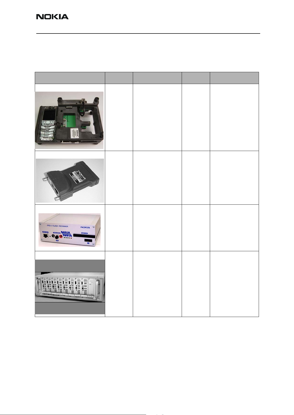
MJ-16 Module Jig 0770575 This jig allows phone
PWB-level service and
troubleshooting. Electric currents should be
protected against
over-voltage and
over-current.
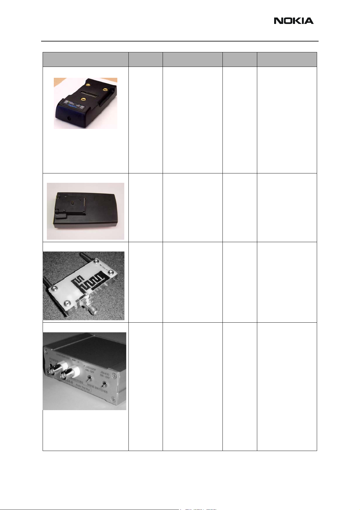
FLS-4S POS Flash Adapter 0080543 The Point of Sale
(POS) flash is a lowcost software upgrade
tool. This requires the
XCS-1 cable and
ACP-8U for operation.
FPS-8 Flash Prommer 0080321 The Flash Prommer
FPS-8 is used for
flash.
FPS-8C Heavy Flash Prommer 0080396 The Heavy Flash
Prommer FPS-8C is
used for heavy parallel flashing.
Issue 1 10/2003 Confidential ©2003 Nokia Corporation Page 3
Page 4
RH-25
Service Tools CCS Technical Documentation
Photo Code Service Tool Code Description
JBV-1 Docking Station 0770298 The Docking Station
and the Docking Station Adapter (DA-15)
are needed for Mbus,
Fbus, RF, and audio
connections.
This setup allows connection between flash
prommers. When the
audio box is connected, it has to be
connected to the
phone’s audio connector.
DA-15 Docking Station
Adapter
CPL-1 Coupler 0770287 The coupler has been
JBA-8 Audio Box 0770320 The Audio Box is
0770624 The Docking Station
can be powered by
FPS-8 or external
power supply.
NOTE: SEE USER
INSTRUCTIONS FOR
DA-15 on page 9.
developed for antenna
go/no go testing.
needed for audio connections. The box
must support DCT4
Janette audios. JBA-8
provides an interconnection between the
phone’s system connector (XEAR, XMIC)
through a fixed audio
cable and audio tester
with a BNC-BNC
coax. Connection to a
PC can be made with
the service battery,
through a DAU-9
cable.
Page 4 ©2003 Nokia Corporation Confidential Issue 1 10/2003
Page 5

RH-25
CCS Technical Documentation Service Tools
Photo Code Service Tool Code Description
SF-15 Flash Adapter 0770625 SF-15 allows a con-
tinuous maximum
power supply for the
phone from an external power supply, the
ACP-8.
NOTE: SEE USER
INSTRUCTIONS FOR
SF-15 ON PAGE 11.
Note: SF-15 is not to
be used for handset
testing; it is only
designed for flashing.
AXP-8 Printer Cable 073F000 The Parallel Printer
Cable connects the
parallel connector of
the PC and the parallel input of the FPS-8.
AXS-4 D9-D9 Cable 0730090 The AXS-4 D9-D9
service cable is used
to connect two 9-pin
connectors (e.g.,
between PC and
FPS-8). AXS-4 length
is 2 meters
CA-X Audio Cable TBD The audio cable con-
nects to the audio box
JBA-8.
SCB-3 DC Cable 0730114 The DC Cable SCB-3 is
used to connect the
docking station to the
charger connection
(Vin) of the phone to
conduct the charger
calibration service
procedure.
Issue 1 10/2003 Confidential ©2003 Nokia Corporation Page 5
Page 6

RH-25
Service Tools CCS Technical Documentation
Photo Code Service Tool Code Description
DAU-9S Mbus Cable 0730108 The Mbus Cable has a
modular connector
and is used with the
service audio box
JBA-4 or a modular
T-adapter.
PCS-1 Power Cable 0730012 The Power Cable
PCS-1 is used to connect the service tools
(JBV-1, MJF-23) to
an external power
supply.
XRF-1 RF Cable 0730085 The XRF-1 cable con-
nects a service tool
and RF measurement
equipment.
XCS-4 Mbus/Fbus Cable 0730178 The XCS-4 Service
Cable is a modular
cable for flashing
DCT4 products.
Page 6 ©2003 Nokia Corporation Confidential Issue 1 10/2003
Page 7

RH-25
CCS Technical Documentation Service Tools
Photo Code Service Tool Code Description
PKD-1 SW Security Device 0750018 SW security device
PKD-1 is hardware
device that, when
connected to the parallel (LPT) port of the
PC, enables the use of
the service software.
Without the dongle
present, it is not possible to use the service software. Printers
or other peripheral
devices can be connected to the PC
through the dongle, if
needed.
Caution: Make sure
that you have
switched off the PC
and the printer before
making connections!
Caution: Do not connect the PKD-1 to the
serial port. You may
damage your PKD-1!
CA-13RS RF Probe 0730300 Spare part for RF
probe used in SA-16
and MJ-16.
SA-16 RF Adapter 0770577 The SA-16 adapter is
used with the DA-15
docking station
adapter, and is needed
for proper RF connection. The adapter
allows galvanic connections to assembled handset RF
switches. The adapter
permits the handset
to be connected to RF
measuring and test
equipment during test
and repair and can be
used with covers on or
off.
Issue 1 10/2003 Confidential ©2003 Nokia Corporation Page 7
Page 8

RH-25
Service Tools CCS Technical Documentation
Flashing and Testing Setups
FPS-8 Flash Prommer for Heavy Flash
The FPS-8 flash prommer is used for heavy flashing. The sales pack product code is
0080321.
FPS-8C Flash Prommer for Heavy Parallel Flash
The FPS-8C flash prommer is used for heavy parallel flashing. The sales pack product
code is 0080396.
Page 8 ©2003 Nokia Corporation Confidential Issue 1 10/2003
Page 9

RH-25
CCS Technical Documentation Service Tools
User Instructions
DA-15 / SA-16
Follow these instructions to avoid damage to the adapter or the phone.
Note: Using the adapter in any way other than described here may harm important pins
and connectors of the adapter. It cannot be used like the FLA-13 for 3520/3560 products.
1 Lock bottom of phone onto the jig.
2 In an arching motion, push phone downward.
3 Push phone down until locks engage.
Issue 1 10/2003 Confidential ©2003 Nokia Corporation Page 9
Page 10

RH-25
Service Tools CCS Technical Documentation
4 Push the probe up from the bottom (photo at left below) and then engage the
locking mechanism (right).
To remove adapter, follow the inverse order of the installation in Steps 1 through 4.
Page 10 ©2003 Nokia Corporation Confidential Issue 1 10/2003
Page 11

RH-25
CCS Technical Documentation Service Tools
SF-15
Follow these instructions to avoid causing any damage to the adapter or the phone.
Note: Using the adapter in any other way may harm the important pins and connectors of
the adapter. It cannot be used like the MJF-2 for 3520/3560 products.
1 Lock bottom of the SF-15 onto the phone.
2 In an arching motion, push the phone and the SF-15 together until the locks
engage.
Issue 1 10/2003 Confidential ©2003 Nokia Corporation Page 11
Page 12

RH-25
Service Tools CCS Technical Documentation
3 To remove, press the tabs on BOTH sides to release.
Page 12 ©2003 Nokia Corporation Confidential Issue 1 10/2003
 Loading...