

Page 1
PAMS Technical Documentation
NPM–9 Series Transceivers
Full Car Kit
CARK132
Installation Guide
Issue 1 02/2002 Nokia Corporation
Page 2

NPM–9
CARK132
PAMS Technical Documentation
CONTENTS
Introduction 3. . . . . . . . . . . . . . . . . . . . . . . . . . . . . . . . . . . . . . . . . . . .
Components of CARK132 4. . . . . . . . . . . . . . . . . . . . . . . . . . . . .
Component Parts 5. . . . . . . . . . . . . . . . . . . . . . . . . . . . . . . . . . . . .
Installation 6. . . . . . . . . . . . . . . . . . . . . . . . . . . . . . . . . . . . . . . . . . .
Testing 7. . . . . . . . . . . . . . . . . . . . . . . . . . . . . . . . . . . . . . . . . . . . . .
Page 2
Nokia Corporation
Issue 1 02/2002
Page 3

NPM–9
PAMS Technical Documentation
CARK132
Introduction
This installation guide has been prepared to provide the basic information necessary
to install CARK132. This guide is not intended to be definitive, because different
types and models of vehicles will require different installation work. The information
given is for general guidance only.
The terms of warranty demand that this car kit be installed by an experienced installer and only genuine Nokia parts are used. An end user should never attempt to
install this car kit without professional assistance as the installation requires special
tools and knowledge.
Please refer to the telephone’s User’s Guide for instructions on the telephone’s operation, care and maintenance, including important safety information.
Note: Read the warnings below before beginning the installation procedure.
WARNINGS
1. ENSURE THAT THE VEHICLE’S BATTERY IS DISCONNECTED BEFORE YOU
START THE INSTALLATION PROCEDURE, AND THAT IT REMAINS DISCONNECTED DURING THE PROCEDURE.
2. DO NOT SMOKE OR USE OPEN FLAMES WHEN WORKING NEAR THE VEHICLE’S FUEL SYSTEM.
3. ENSURE THAT THE VEHICLE’S ELECTRICAL CABLES, HYDRAULIC LINES,
FUEL LINES, AND SAFETY EQUIPMENT ARE NOT DAMAGED DURING INST ALLA TION.
4.ENSURE THA T NORMAL CONTROL AND OPERATION OF THE VEHICLE IS NOT
IMP AIRED BY THE INSTALLA TION, P ARTICULARLY THE BRAKES AND STEERING. ENSURE THAT AIRBAG OPERATION IS NOT OBSTRUCTED.
5.ELECTRONIC AND OTHER SOPHISTICATED SYSTEMS (e.g. SPEED CONTROL, ABS ANTI-LOCK BRAKE, FUEL INJECTION-, NAVIGATION-, AND AIRBAG SYSTEMS) ARE RELATIVELY IMMUNE TO MALFUNCTION CAUSED BY
NEARBY RADIO TRANSMISSIONS. HOWEVER, SHOULD YOU EXPERIENCE
FALSE OPERA TION OF THESE SYSTEMS OR ARE IN ANY DOUBT WHA TSOEVER AS TO THEIR FUNCTIONALITY, PLEASE CONSULT THE VEHICLE’S DEALER.
6.THE CAR KIT IS SUITABLE FOR USE ONLY IN VEHICLES WITH A 12 V NEGATIVE GROUNDING. USE ON OTHER SUPPLY VOLTAGES OR ALTERNATIVE
POLARITY WILL DAMAGE THE EQUIPMENT.
7.THE NOKIA PHONE SHOULD NOT BE LEFT SWITCHED ON FOR EXTENDED
PERIODS WITHOUT RUNNING THE VEHICLE’S ENGINE. F AILURE TO COMPL Y
COULD DRAIN THE VEHICLE’S BATTERY.
Issue 1 02/2002
Nokia Corporation
Page 3
Page 4

NPM–9
CARK132
Components of CARK132
The CARK132 includes the following parts:
Advanced Active Car Holder MCC–5
Advanced HF Unit HFU–5
Power Cable PCH–4J
Mounting Plate MKU–1
Swivel Mount HHS–9
HF Microphone HFM–8
HF Speaker HFS–12
PAMS Technical Documentation
HHS-9
AMD–2
HFS–12
MCC-5
MKU–1
HFU-5
PCH-4J
HFM-8
Please, note that the items enclosed in broken-line (phone & antenna) are not supplied with CARK132. The external antenna AMD–2 is recommended.
Page 4
Nokia Corporation
Issue 1 02/2002
Page 5
NPM–9
PAMS Technical Documentation
CARK132
Component Parts
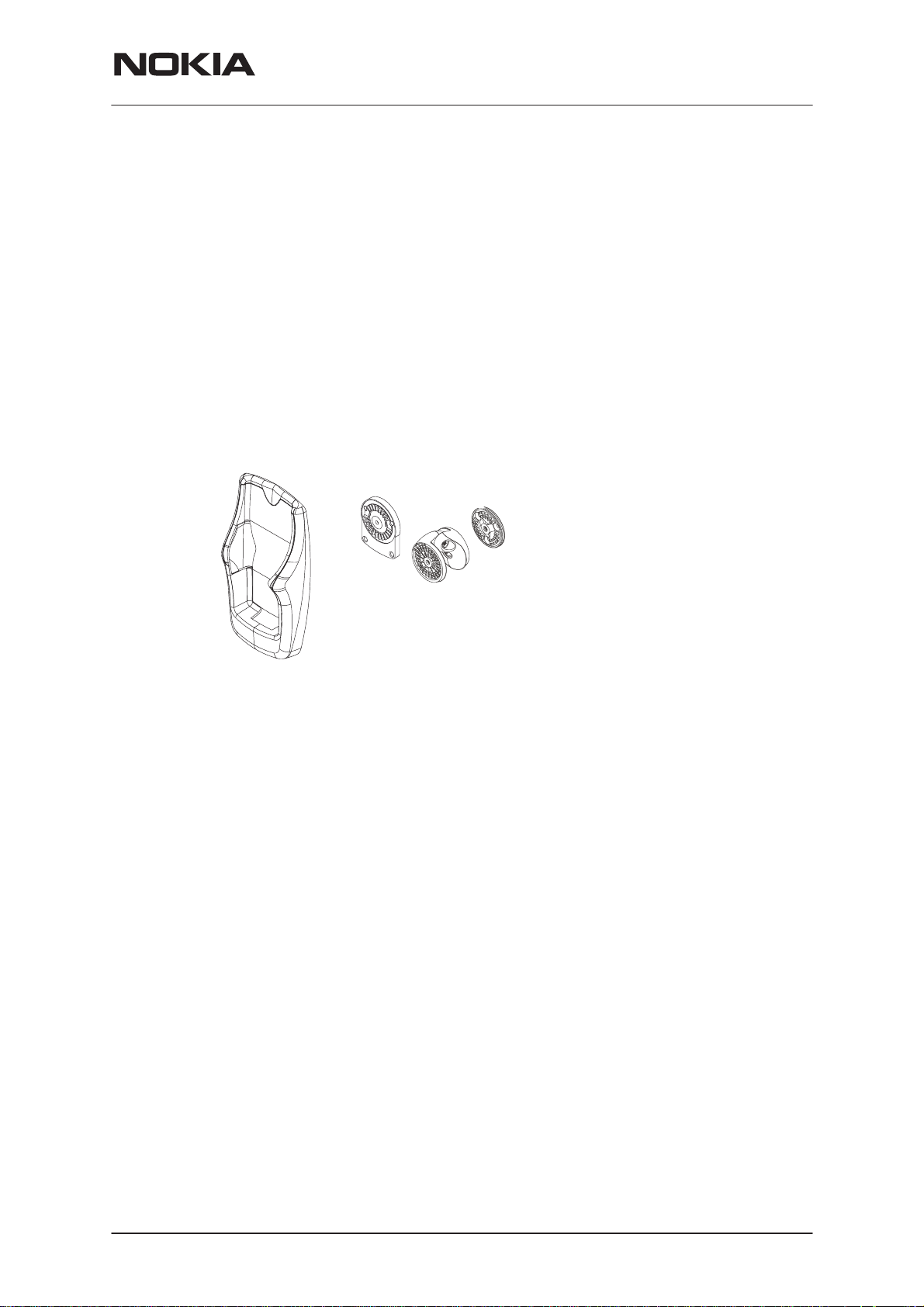
Advanced Active Car Holder MCC-5
The holder for the mobile phone is attached to the vehicle’s interior always in an upward position, shown in Fig. 2 below, using the swivel mount HHS-9. The mounting
is secured with a screw (included with HHS-9). The screw recess is covered with the
NOKIA logo plate.
The cable with the plug-in connector from MCC-5 connects to the PHONE socket in
HFU-5 (The other cable from MCC-5 connects to the external antenna.)
Swivel Mount HHS-9 and Mounting Plate MKU-1
HHS-9 is a swivel mount which offers two installation methods for the holder MCC-5.
Either use all components to make a swivel mount, or use the flat mounting plate for
a fixed position.
For an exploded view, see Figure 2.
FIG.2
Mounting plate MKU–1
The handsfree unit HFU-5 is attached to the vehicle interior using the mounting plate
MKU–1. The mounting is secured with a screw (included with MKU–1).
Advanced HF Unit HFU-5
The handsfree unit HFU-5 enables the phone to operate in handsfree mode and it is
attached to the vehicle interior using the mounting plate MKU-1. The mounting is secured with a screw (included with MKU-1).
Power Cable PCH-4J
The power cable connects to the DC socket in HFU-5 and to the vehicle’s power
supply. See section ”Installation” for more information.
HF Microphone HFM-8
The HF microphone connects to the MIC socket in HFU-5. Twist the plug clockwise
to lock firmly in place.
HF Speaker HFS-12
The HF speaker connects to the SPEAKER socket in HFU-5. Twist the plug clockwise to lock firmly in place.
Antenna Set NMT/GSM 900/1800 AMD–2 (not included)
The external antenna AMD–2 is recommended for the car kit. It connects to MCC-5.
For additional information please refer to documentation supplied with the antenna.
Issue 1 02/2002
Nokia Corporation
Page 5
Page 6

NPM–9
CARK132
PAMS Technical Documentation
Installation
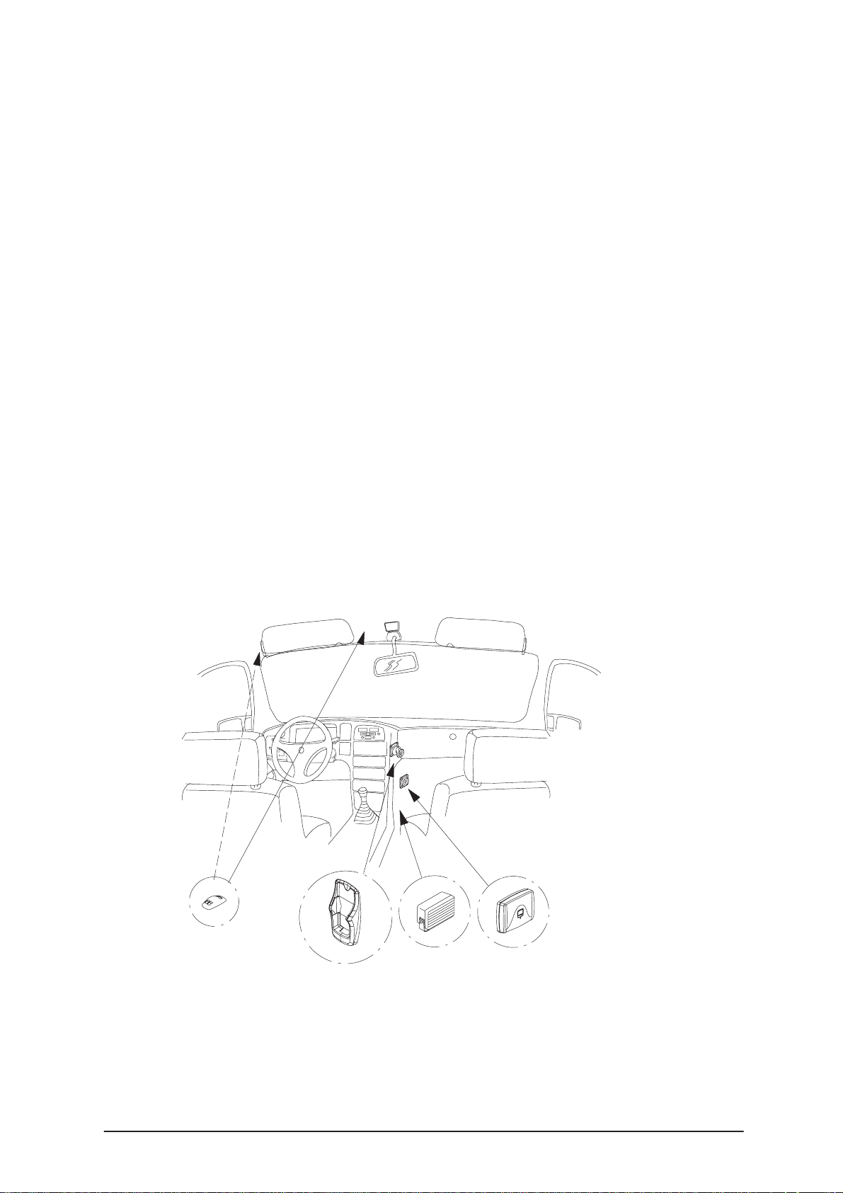
For an example of installation locations, please see the CARK132 cover page.
Note: Ensure that the battery of the vehicle is disconnected before you start the
installation or making changes to the installations, and that it remains disconnected
during the installation procedure.
The HFU-5 and the different parts are connected as mentioned in the section ”Component Parts”.
There are some important aspects that require special attention in positioning car kit
accessories.
The location of the holder should be selected so that the holder is always in an upward position (see Fig.2) and that the visibility of phone’s display is good and the
driver’s attention is not distracted. The location of holder should allow the driver to
easily reach the keypad. Under no circumstances should the holder prevent the driver from controlling or operating the vehicle in any way.
The HF microphone should be installed according to the directions in the separate
microphone installation guide. Ensure the microphone is as close to the driver’s
mouth as possible, and attached to a surface that is mechanically quiet. The microphone should be mounted at least 3 ft/1 m away from the handsfree unit speaker to
avoid acoustic feedback.
Ensure the cables are routed as far away as possible from the vehicle’s electronic
systems. This is to prevent interference. Also, ensure that cables are not subjected
to undue mechanical stress e.g. under seats or against sharp edges.
PCH-4J
The cables from PCH-4J are colour coded. They are listed in the following table in
column A and each cable should be connected to the corresponding item listed in
column B.
A B
Red cable (with 2 amps fuse) The + voltage on the vehicle’s power supply.
Black cable The negative GND connection.
Blue cable (with 1 amp fuse) This cable should be left unconnected.
Yellow cable Used for car radio muting (CRM) and is connected
to car radio. The line goes down to 0 volts during a
call. See section ”Car Radio Muting CRM”.
Green cable (with 1 amp fuse) This cable should be left unconnected.
Page 6
Nokia Corporation
Issue 1 02/2002
Page 7

NPM–9
PAMS Technical Documentation
CARK132
Car Radio Muting CRM
The car kit offers a feature that can mute the car radio automatically during a conversation. The following is the circuit diagram of CRM.
Relay (12 V)
GND
CAR
RADIO
87A
87
30
12 V d.c.
Supply for
car radio
To CRM line
(yellow wire)
85
86
Fuse 200 mA
(not supplied)
12 V d.c.
Another possibility is to use a special muting unit, which mutes the radio by connecting load resistors to the speaker lines of the car radio.
All installations should take into account any special requirements of the customer.
However, should the customer require an installation that is illegal or unsafe these
facts must be pointed out to the customer and a policy of non-compliance adopted.
Testing
Once installed, the equipment should be tested to ensure that it is operating satisfactorily and that the position of the units does not impair the driver’s ability to control and operate the vehicle in any way.
Issue 1 02/2002
Nokia Corporation
Page 7
Page 8

NPM–9
CARK132
PAMS Technical Documentation
This page intentionally left blank.
Page 8
Nokia Corporation
Issue 1 02/2002
 Loading...