


Nokia 63L3, 71L3, 74F3 Schematic
MULTI CONCEPT
57
MX-CHASSIS
(100 Hz, 4:3)
G Service manual
D Service-Manual
S Serviceanvisning
n
TV
1998
F Manuel de service
I Manuale di servizio
TV 2561-TN 100 Hz
TV 2861-TN 100 Hz
TV 2961-TN 100 Hz
TV 2561-T Multi 100 Hz
TV 2861-T Multi 100 Hz
TV 2961-T Multi 100 Hz 3D VGA
63L3-TN 100 Hz
71L3-TN 100 Hz
63L3-T Multi 100 Hz
71L3-T Multi 100 Hz
74F3-TN 100 Hz
74F3-T Multi 100 Hz 3D VGA
6611 7280

58
G Contents
Repair instructions .....................................................................................................................................................................1
Technical data .............................................................................................................................................................................2
Block diagrams ...........................................................................................................................................................................3
SCART connector ....................................................................................................................................................................... 6
Operating instructions ...............................................................................................................................................................7
Initialization of NVRAM..............................................................................................................................................................7
Service adjustments...................................................................................................................................................................8
Schematic diagrams ................................................................................................................................................................ 27
Variable components ............................................................................................................................................................... 43
Spare parts................................................................................................................................................................................44
D Inhaltsverzeichnis
Reparatur Anweisung ................................................................................................................................................................1
Technische Daten ....................................................................................................................................................................... 2
Blockschaltbilden ....................................................................................................................................................................... 3
SCART Anschluß ........................................................................................................................................................................6
Bedienungsanleitung ...............................................................................................................................................................11
Initialisierung des NVRAM ...................................................................................................................................................... 11
Service-Einstellungen .............................................................................................................................................................. 12
Schaltpläne ............................................................................................................................................................................... 27
Röhrenabhängige Bauteile ......................................................................................................................................................43
Ersatzteileliste ........................................................................................................................................................................... 44
S Innehåll
Reparationsinstruktioner ........................................................................................................................................................... 1
Tekniska data .............................................................................................................................................................................. 2
Blockschemor ............................................................................................................................................................................. 3
SCART-kontakt ............................................................................................................................................................................ 6
Bruksanvisning .........................................................................................................................................................................15
Initialisering av NVRAM...........................................................................................................................................................15
Serviceinställningar ................................................................................................................................................................. 16
Kopplingsschemor ................................................................................................................................................................... 27
Komponentskillnader ............................................................................................................................................................... 43
Reservdelar ...............................................................................................................................................................................44
F Contenu
Instructions de reparation ......................................................................................................................................................... 1
Données techniques...................................................................................................................................................................2
Diagrammes des blocs .............................................................................................................................................................. 3
Connecteur SCART.....................................................................................................................................................................6
Mode d'emploi ......................................................................................................................................................................... 19
Initialisation de la NVRAM.......................................................................................................................................................19
Réglages de service ................................................................................................................................................................. 20
Schéma ..................................................................................................................................................................................... 27
Composants variables ............................................................................................................................................................. 43
Pièces de rechange .................................................................................................................................................................. 44
I Indice
Istruzioni di servizio ................................................................................................................................................................... 1
Dati tecnici .................................................................................................................................................................................. 2
Diagramma di blocco ................................................................................................................................................................. 3
Connettore SCART .....................................................................................................................................................................6
Istruzioni d'uso ......................................................................................................................................................................... 23
Inizializzazione della NVRAM .................................................................................................................................................. 23
Regolazioni di servizio ............................................................................................................................................................. 24
Schema elettrico.......................................................................................................................................................................27
Componenti che differiscono ..................................................................................................................................................43
Parti di ricambio ....................................................................................................................................................................... 44
Copyright © 1998 by Semi-Tech (Turku) Oy. All Rights Reserved. www.semitechturku.com

1
G Repair instructions
Service and repair work must be performed only in
accordance with existing safety regulations!
Where a high current or mechanical stress exists solder
connections have been strengthened by using eyelets. Such a
connection must not be left without an eyelet.
Wiring has an effect on safety and EMC (Electro-Magnetic
Compatibility). Therefore wires must be maintained in their
original positions.
X-RAY REGULATIONS:
The picture tube type and the maximum permissible highvoltage ensure that the X-ray intensity of the receiver remains
far below the permissible value. The high-voltage must not
exceed the value mentioned on the type label. The high
voltage is within the permissible limits when the operating
voltage (U1) of the horizontal deflection stage is accurate.
Refer to the section “Service adjustments”.
ESD Warning
The receiver contains components that are sensitive to
electrostatic discharge (ESD). Any servicing or repair work
must be done in an environment where the components will
not be subjected to ESD. Use a special grounding device!
D Reparatur Anweisung
Bei Reparaturen gültige Sicherheitsvorschriften beachten!
Lötverbindungen die einem hohen Stromfluß oder starker
mechanischer Beanspruchung unterliegen wurden durch
Lötösen verstärkt. Eine derart belastete Lötverbindung darf
nicht ohne Lötöse verbleiben.
Die Lage der Kabel hat einen Einfluß auf die Betriebssicherheit
und das EMV Verhalten (Elektro Magnetische Verträglichkeit)
des Geräts. Aus diesem Grund müssen die Kabel in ihrer
orginalen Position verbleiben.
RÖNTGENVERORDNUNG:
Der Bildröhrentyp und die maximal zulässige Hochspannung
stellen sicher, daß die Röntgenstrahlenintensität des
Fernsehgerätes weit unter dem zulässigen Wert bleibt. Die
Kathodenhochspannung darf den auf dem Typenschild
angegebenen Wert nicht überschreiten. Die Hochspannung
liegt im zulässigen Bereich, wenn die Betriebsspannung (U1)
der Horizontal-Ablenkstufe genau eingehalten wird. Siehe
auch Abschnitt “Service-Einstellungen”.
EGB-Warnung
Das Fernsehgerät enthält Bauteile, die empfindlich auf
elektrostatische Entladung reagieren. Alle Service- oder
Reparaturarbeiten sind in einer Umgebung durchzuführen, in
der die Bauteile nicht elektrostatischer Entladung ausgesetzt
sind. Verwenden Sie eine spezielle Erdungsvorrichtung!
RÖNTGENSTRÅLNING:
Med hjälp av bildrörstyp och begränsning av maximum
högspänning kan mottagarens röntgenstrålning hållas under
tillåten nivå. Höspänningen får inte öveskrida värdet som
näms på typetiketten. Högspänningen är inom tillåten nivå när
horisontalslutstegets drivspänning (U1) är rätt inställd. Se
avsnitt “Service inställningar”.
ESD (Statisk elektricitet)
Mottagaren är utrustad med komponenter som är känsliga för
statisk elektricitet (ESD). Servicearbetet måste därför göras så
att komponenterna inte utsätts för statisk elektricitet. Använd
speciell jordningsutrustning.
F Instructions de reparation
Veuillez observer les prescriptions de sécurité en viguer lors
de dépannage !
Les connections par soudure doivent être consolidées par des
oeillets lorsqu’elles sont soumises à des tensions importantes
et à des contraintes mécaniques. De telles connections
doivent toujours être faites à l’emplacement d’un oeillet.
Le câblage a un effet sur la sécurité et les perturbations
électromagnétiques. Pour cette raison les câbles doivent
garder leur position originale.
REGLEMENTATIONS RELATIVES AUX RAYONS X:
Le type du tube image et la haute tension maximale autorisée
garantissent une intensité des rayons X du récepteur
largement en deçà de la valeur autorisée. La tension ne doit
pas dépasser la valeur indiquée sur la plaquette signalétique.
La haute tension reste dans la fourchette autorisée lorsque la
tension de sevice (U1) du niveau de déflexion horizontale est
précise. Reportez-vous à la section “Réglages de service”.
Avertissement DES
Le récepteur contient des composants qui sont sensibles aux
décharges électrostatiques (DES). Toute opération de
maintenance ou de réparation doit être effectuée dans un
environnement où les composants ne seront pas exposés à
des décharges électrostatiques. Utilisez un dispositif de mise à
la terre spécial !
I Istruzioni di servizio
Osservare le norme di sicurezza vigenti in caso di riparazioni!
I punti di collegamento del circuito stampato che conducono
un elevato valore di corrente o sono soggetti a stress
meccanico, sono stati rinforzati mediante Rivetti. Tali parti
rinforzanti devono rimanere sepre inseriti.
Il cablaggio puo’ influenzare la sicurezza e la compatibilita’
elettromagnetica (EMC) dell’apparecchio. Si raccomanda di
mantenere il cablaggio nella posizione originale.
S Reparationsinstruktioner
Gällande säkerhetsdirektiv måste beaktas vid service-ingrepp!
Lödpunkter, som kan utsättas av hög ström eller mekanisk
belastning, har förstärkts genom holkning. Dessa lödpunkter
får inte lämnas utan denna förstärkning.
Kabeldragningen inverkar på säkerhet och EMC
(Elektromagnetisk anpassning). Kabel-dragningen måste
därför utföras enligt originalutförande.
REGOLAMENTAZIONE DEI RAGGI-X:
Il tipo di tubo catodico unitamente all’uso del massimo livello
di alta tensione consentito fanno sì che l’intensità dei raggi X
del ricevitore rimanga molto al di sotto del valore consentito.
Il valore della tensione elevata (EAT) non deve superare il
limite indicato sul tagliando dell’apparecchio. L’alta tensione
rientra nei limiti consentiti se la tensione operativa (U1) del
livello di deflessione orizzontale è corretta. Fare riferimento
alla sezione “Regolazioni di servizio”.
Avvertenza ESD (scariche elettrostatiche)
Il ricevitore contiene componenti sensibili all’elettricità statica.
Qualsiasi intervento di assistenza tecnica o riparazione deve
essere eseguito in un ambiente in cui i componenti non
possano essere soggetti a scariche elettrostatiche (ESD). A tal
fine, usare uno specifico dispositivo di messa a terra!

2
Technical data
System
Multinorm
NTSC
Mains power
Consumption
In stand-by
Frequency range
Sound output (RMS)
Surround channel
Centre channel
Subwoofer
Connections on the front
panel
Headphones
Audio/Video
Connections on the rear
panel
Audio/Video
2)
1)
2)
2)
2)
Technische Daten
Norm
Multinorm
NTSC
Netzanschluß
Leistungsaufnahme
Im Bereitschaft
Frequenzbereich
Tonendstufe (RMS)
Surround
Mitte
Subwoofer
Anschlüsse an der
Vorderseite
Kopfhöreranschluß
Audio/Video
Anschlüsse an der Rückseite
Audio/Video
2)
1)
2)
2)
2)
Tekniska data
Norm
Multinorm-TV
NTSC
Nätanslutning
Effektförbrukning
I beredskapsläget
Frekvensområde
Ljudeffekt (RMS)
Surroundkanal
Centrumkanal
Subwoofer
Anslutningar på framsidan
Hörlurar
Audio/Video
Anslutningar på baksidan
Audio/Video
2)
1)
2)
2)
2)
Données téchniques
Systéme
Téléviseurs multinormes
NTSC
Alimentation
Consommation
1)
En mode veille
Gamme de fréquences
Sortie sonore (RMS)
Canaux Surround
Canal central
Subwoofer
2)
2)
Connexions sur le panneau
avant
Ecouteurs
Audio/Vidéo
Connexions sur le panneau
arrière
Audio/Vidéo
2)
2)
Dati tecnici
Sistema
Televisori multistandard
NTSC
Tensione di alimentazione
Consumo energetico
In standby
Campo di frequenza
Potenza audio (RMS)
Canali Surround
Canale centrale
Subwoofer
2)
2)
Connessioni sul pannello
frontale
Cuffia
Audio/Video
Connessioni sul pannello
posteriore
Audio/Video
2)
1)
2)
PAL/SECAM B, G
PAL/SECAM B, G, D, K, K1, L, L’, I
3.58/4.43 MHz via Scart
210...240 V, 50 Hz
135 W (normal)
0.2 W
48.25 - 855.25
2 x 10 W/8 Ω
2 x 6 W/16 Ω
10 W/8 Ω
14 W/16 Ω
32...600 Ω, 3.5 mm
Audio in: 0...2 V (RMS)
Video in: 1 V/75 Ω
Y/C in (SVHS)
Audio in: 0...2 V (RMS)
Audio out: 0...2 V/10 kΩ (RMS)
Video in/out: 1 V/75Ω
RGB in: 0.7 V/75Ω (E1, E3
2)
)
Y/C in (SVHS) (E2)
External loudspeakers
Surround loudspeakers
Centre loudspeaker
2)
2)
Antenna
Audio output
VGA input
VGA audio input
2)
2)
2)
Specifications are subject to
change.
1)
Depends on option modules
and picture tube.
2)
Not in all models.
Externe Lautsprecher
Surround-Lautsprecher
Mitte-Lautsprecher
2)
2)
Antennenanschluß
Audio Ausgang
VGA Eingang
VGA Audio-Eingang
2)
2)
2)
Änderungen vorbehalten
1)
Abhängig von
Optionsmodulen und
Bildröhre.
2)
Nicht in allen Modellen.
Extrahögtalare
Surroundhögtalare
Centrumhögtalaren
2)
2)
Antenn
Ljudutgångar
VGA ingång
VGA ljudingång
2)
2)
2)
Rätt till ändringar
förbehålles.
1)
Varierar beroende på moduluppsättning och bildrör.
2)
Inte i alla modeller.
Haut-parleurs externes
Haut-parleurs Surround
Haut-parleurs Central
2)
2)
Antenne
Sortie audio
Entrée VGA
Entrée audio VGA
2)
2)
2)
Les Spécifications peuvent
êt re modifiées sans préavis.
1)
Dépend des modules optionnels et du tube cathodique.
2)
Pas sur tous les modèles.
Altoparlanti esterni
Altoparlanti Surround
Altoparlanti centrale
2)
2)
Antenna
Uscita audio
Ingresso VGA
Ingresso audio VGA
2)
2)
2)
Le specifiche sono soggette
a cambiamenti.
1)
A seconda dei moduli opzione
e del tubo catodico.
2)
Non in tutti i modelli.
min 10 W/8 Ω (RMS)
min 6 W/16 Ω (RMS)
min 10 W/8 Ω (RMS)
75 Ω
0...2 V/10 kΩ (RCA)
640 x 480, 60 Hz
640 x 400, 70 Hz
640 x 350, 70 Hz
0...2 V (RMS) (RCA)
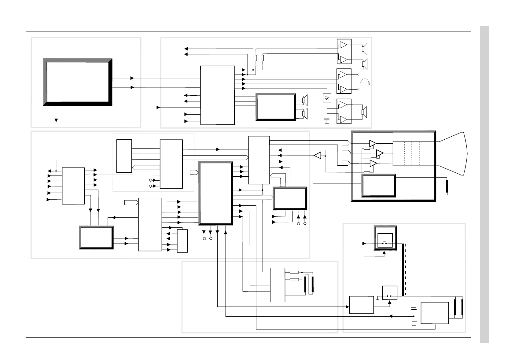
Block diagram, signal routes
15
20, 22, 24
19
10-12
13
fb
2-4
1
fb
bcl
BC
8
6
7
ICt1
ICr2
44-46
18-27
ICr1
47
BLAN
14
13
12
Y
ICd1
25
26
V
U
ICd3
4
2
3
1
RGB + fb
17
18
16
15
14
C
CVBS/Y
C
ICq1
OUT
OUT
13
3
11
IN
IN
CVBS/Y
5, 6
IN
8, 10
IN
2H
2V
14
sc
17
11
HA
VA
10
SSc
D1
D0
D2
D3
32
33
34
35
I/O2
I/O1
I/O3
I/O4
2
1
24
25
9
CVBS
3
2V
4
2H
A0-A9
RGB
ICs1
Mk1
DATA IN
DATA OUT
WS
L
R
CL
L, R
L, R
L, R
AM
SIF
R, L
R, L
L
R
3D/Pro Logic
module
AR7xx
4
6
1
7
ICa1
29
28
26
25
9
1
ICa2
2
6
33, 34
36, 37
46, 47
49, 50
52, 53
55
60
14
13
12
11
5
6
7
8
SOUND BLOCK
CRT module
HH7xx
ICh3
ICh2
ICh1
R
G
B
6
5
4
9
7
BC
SVM
module
VMxxx
PIP
module
PP7xx
RGB
RGB
IQTV2
&
DPLL
DB7xx
Flyback
EW
Ver
Ver
Hor
sc
11
14
12
16
Comb filter
module
CF7xx
V
Y
U
11
10
67
13
15
14
18-21
Scart 1
34
35
33
37
38
Camera
Scart 2
Scart 1
RF BLOCK
PIP
module
109
C
CVBS/Y
11 12
Scart 2
Scart 2
RGB
2H
2V
27 26
24
TELETEXT
VIDEO BLOCK
Adjustable
audio
Scart 1
Camera
Scart 3
VGA
Scart 2
Scart 1
17
Y
Tk3
SWxxx
U1
12V
22
17
20
19
18
12
11
1
9
2
Scart 1
26
Y
SVM coil
Diode
modulation
Dk7, Dk8
Tk4,ts1,ts2
5
Vertical
deflection
yoke
Horizontal
deflection
yoke
Line
driver
Tk1, Tk2
Vertical
deflection
and
E-W driver
Horizontal
deflection
5,9-12,14-18
MSP3410D
Audio
processor
TDA9143
Colour
decoder
TDA4780
RGB processor
SDA5275S
Megatext
514400
Text memory
TEA6417
Video switch
TDA8354
Vertical output
TDA2616
Audio power
amplifier
TL082
Headphone
amplifier
TV-Frontend
Tuner+IF
19
18
20
PIP
CVBS
1
Scart 3
IN
IN
23
1
Fsc
clock
VGA
VGA/RGB
5
6
4
ICa4
1
9
TDA2616
Active subwoofer
amplifier
ICa3
31
SUB
3
4
Scart-
buffers
TXT
ICr1
RAM
ICr2
Delay
ICd3
Deco/Sync
ICd1
RGB-proc.
ICt1
ROM
ICf1
NVM
ICf2
µP
ICf3
Video Switch
ICq1
HP-Ampl.
ICa3
Service
conn. &
buffer
Sound
processor
ICa2
Frontend
PIF SIF
TV-
Tuner
ICo6
Rec
ICo3
Rec
5V-r
12V-r
To4
Pict
12V-p
SVM module
CRT-module
8V-p
FEATURE BOX
32
30
8V-p
Comb-Filter
3
4
PIP-module
Decoder
ICp3
µP, ICp6
&
A/D, ICp5
13
12V-p
7V-fb
8V-p
12V-p
7
28
5
5V-r
Amplifiers
Digital Sound
Processor
5V-r
12
1
28V
ICo4
12V-r
10V
5V-stb
Control module
IR-
receiver
8
10
6
12V-p
5V-stb
Loudspeaker
Amplifier
ICa1
PP7xx
Rq48
AR7xx
FC7xx
CF7xx
20
22
23
24
15
17
18
14
21
19
3
4
ICo2
3
2
11
5
ICo1
6
16
1
14
Ro8,
14
Do8
Co10
Do2
Do1
Do4
Do3
Ro4, 10
Ro15
Ro18, 19
21, 22
To1
Ro70
Co15
230V
50Hz
Ftc1
Fo1
Do12
Do11
Do9
Do13
U1
32
PWM
Line
sync.
Do17
Ro32
Fo3
Fo2
Do14
Do16
Ro42
Ro45
Ro50
Do20
8
2
5
!
!
Ro44, 46
ZDk1
7V
Mains non isolated
17V
7V-fb
Ro49
Ro48
!
Mo2
!
Mo3
!
Vert.deflection
& EW driver
ICs1
Mk1
Rk2
Dk1
8
10
11
12
1
7
Rk9
Dk2
Rk19
Dk3
6.3V RMS
30kV
500V
8 kV
Rk15
Rk45
200V
53V
Rk4
!
!
!
!
!
Tk3
Rk20
!
16V
SWxxx
Rk11, 12
13, 14
HH7xx
Line
driver
12V-p
12V-p
12V-p
!
7V
G2
Focus
Heater
5
4
3
6
12V-p
8V
Ra18
AUX
module
12V-p
TA700
And
ICf4
Reset
ICf5
Subwoofer
Amplifier
ICa4
I
2
C Switch
11
30V
2
30V
Rq54
Rq2
Tq5
8.5V
Rr18
Scart 3 module
TA710/711
4
10
Tuner
To15
To9
Cfc23
FC7xx
Control module
Start
ICfc1
ICfc2
2
1
47
14
Cfc24
Cfc26
Dfc11
Hfc2
3
Zdo1,To8
RGB
Switch
ICp7
I
2
C Switch
ttp5
IF
ICp1
Delay-line
ICp4
DB7xx
SR7xx
Cancellor
VMxxx
Defl. ctrl
IC17
Filters
5V
3V
IC1
DSP
IC4
IQTV
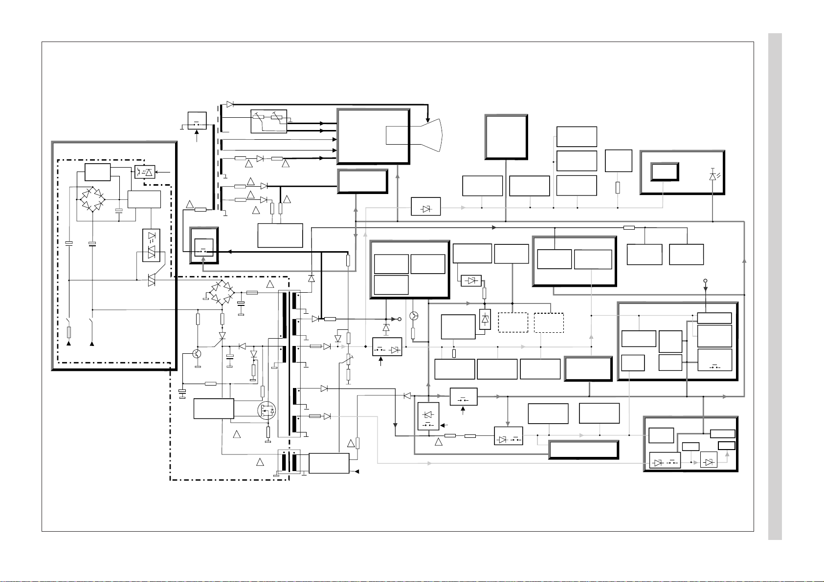
Block diagram, power supply
µP
ICf3
PIP-MODULE
FEATURE BOX DB7xx
Comb-Filter
module
TV tuner
SDA
SCL
+5V
Local control
HP ind
Rec / IR
IR Receiver
TXT
ICr1
M3L
Status 2
Status 1
Status 3
Hold
Surround
processor
ICar2
Sound
processor
ICa2
Deflection
IC 17
IQTV µP
IC 18
Deco/Sync
ICd1
Subwoofer
mute
5
MSP Reset
Bypass /
Comb-ID
NTSC
RGB processor
ICt1
Video Switch
ICq1
NVM
ICf2
PIP µP
ICp6
Deco/Sync
ICp3
Video switch
PIP/ext. RGB
Service
connector
54
53
52
7
50
1
61 62
46
64
44, 45
4, 59, 60
AUDIO FEATURE BOX
17, 18
5, 6
8, 9
17, 18
5, 6 2, 4 27, 28
9, 10
49, 50, 51
51, 61
85
DPLL
IC 11
40, 41
9,10
24
40,41
3, 4
1, 2
3
PIP tuner
IF
ICp1
L-norm
15
16
37
38
VGA
1/2 FM
Bridges:
Mute
2
7
E3-control
(3-state)
&
APSi
test
Subwoofer
ident.
RGB
status
Line-out
status
6
3
FRONTEND
Multi: Strobe to write I/O-latch
Single: APSi control
IF ident.
resistor
APSi filter/Strobe
Strobe
APSi
(Single norm)
47
55
IF Ident.
15
16
23
13
2
1
5, 6
FSC /
SVHS
263
AV-link
PWM
Scart pin 10
16:9 ident.
51
12Vp
PA-mute
&
OR
28V
PA
PA
mute
mute
Subwoofer
Int-LS
15
4
I
2
C
I
2
C
DSP Reset
12V
4, 57, 8
10
A/D
Hor. shift
5
A/D
A/D
A/D
4, 5
8
8
ΤΑ700
8,9
Picture tilt
PWM
1
)
1
)
1) If no mux. and
picture tilt
mux.
ΤΑ710
Upict
Urec
U
49
48
Start
Rec-on
Pict-on
11 = Off
00 = TV
01 = Record
10 = Service
3
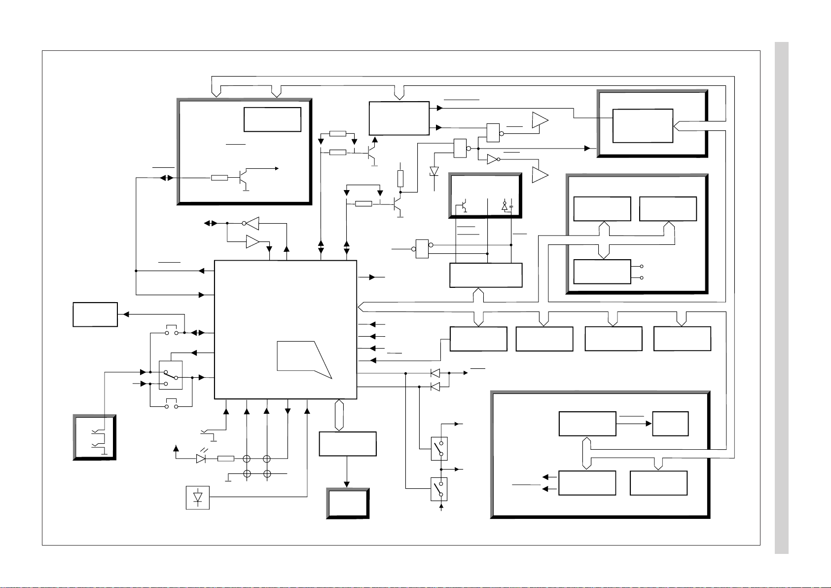
Block diagram, control signals
5
6
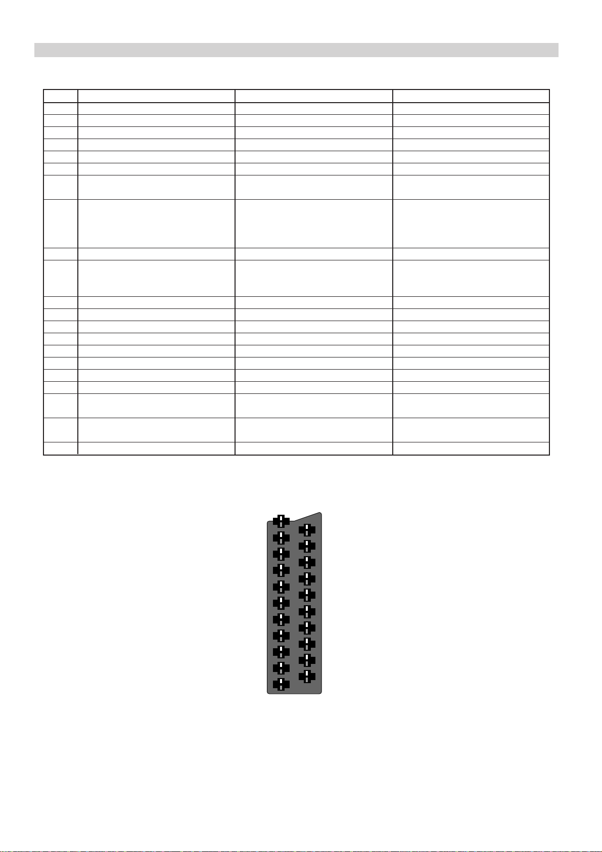
SCART connector
Pin SCART 1 SCART 2 SCART 3 (Not in all models)
1 Audio out R, 0.5V (RMS) Audio out R, 0.5V (RMS) Audio out R, 0.5V (RMS)
2 Audio in R, 0.5V (RMS) Audio in R, 0.5V (RMS) Audio in R, 0.5V (RMS)
3 Audio out L, 0.5V (RMS) Audio out L, 0.5V (RMS) Audio out L, 0.5V (RMS)
4 Ground, audio Ground, audio Ground, audio
5 Ground, blue Ground Ground, blue
6 Audio in L, 0.5V (RMS) Audio in L, 0.5V (RMS) Audio in L, 0.5V (RMS)
7 RGB input, blue S-video chrominance out RGB input, blue
(copy from front AV-connector)
8 Switching voltage Switching voltage Switching voltage
0 - 2V : no function 0 - 2V : no function 0 - 2V : no function
4.5 - 7V : 16/9 picture ratio 4.5 - 7V : 16/9 picture ratio 4.5 - 7V : 16/9 picture ratio
9.5 - 12V : normal picture ratio 9.5 - 12V : normal picture ratio 9.5 - 12V : normal picture ratio
9 Ground, green Ground Ground, green
10 - AV-link bidirectional control -
logical 0: max 0.6V
logical 1: min 3.7V
11 RGB input, green - RGB input, green
12 --13 Ground, red S-video ground (chrominance) Ground, red
14 Ground Ground Ground
15 RGB input, red S-video input (chrominance) RGB input, red
16 Switching voltage, RGB blanking - Switching voltage, RGB blanking
17 Ground, video Ground, video Ground, video
18 Ground Ground Ground
19 Video out, 1 Vpp/75 Ω Video out, 1 Vpp/75Ω Video out, 1 Vpp/75 Ω
S-video out (luminance)
20 Video in, 1 Vpp/75 Ω Video in, 1 Vpp/75 Ω Video in, 1 Vpp/75 Ω
RGB sync in S-video in (luminance) RGB sync in
21 Screen Screen Screen
21
19
17
15
13
11
20
18
16
14
12
9
7
5
3
1
10
8
6
4
2
Operating instructions
7
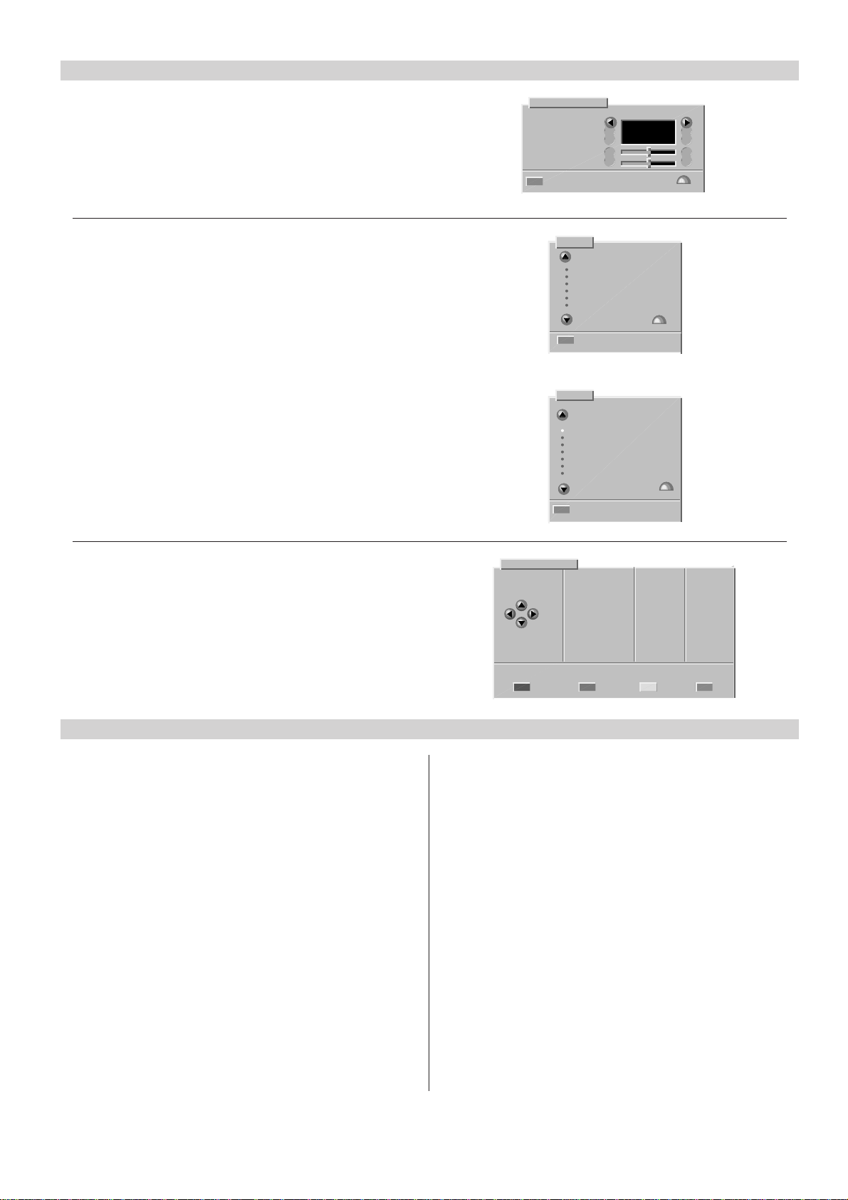
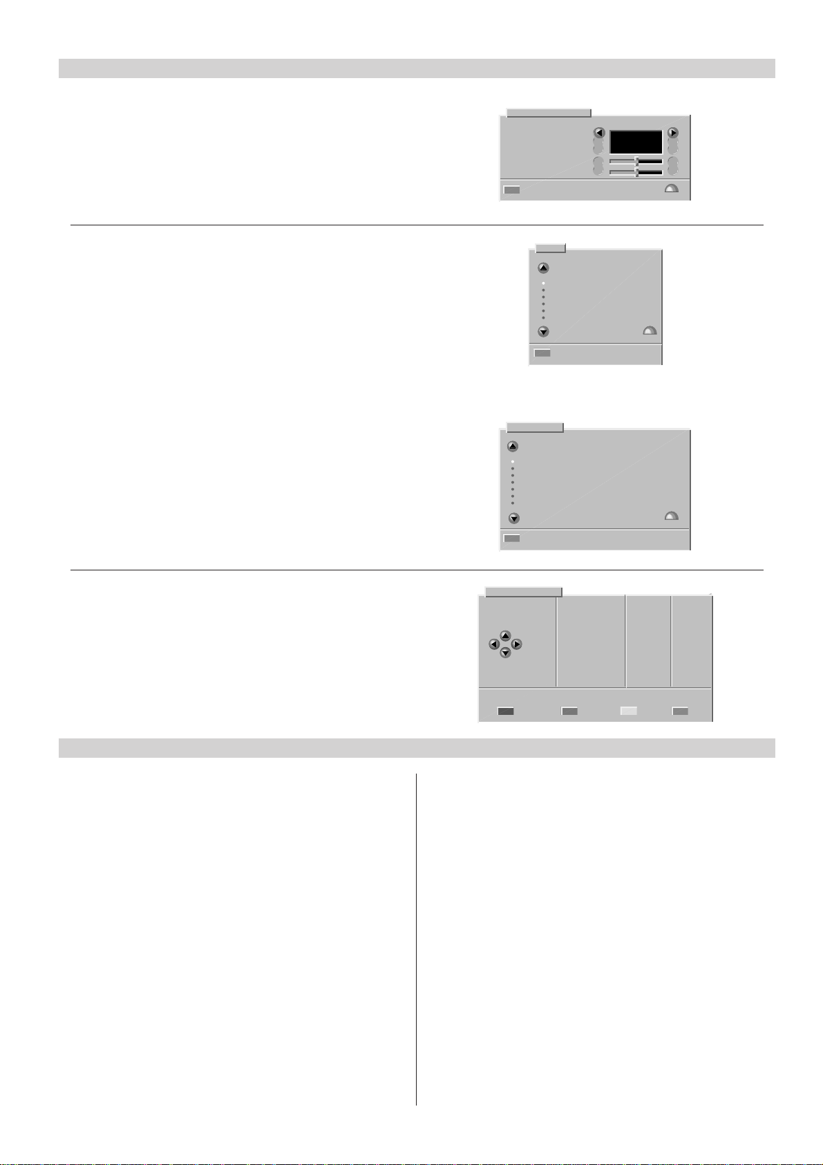
Changing the menu language
1. Press the yellow button to select the Vision menu.
2. Press the red button to select the Display set-up menu.
3. Change the menu language with cursor buttons.
4. Press the OK button to store the changes.
5. Press the TV button to exit.
Manual tuning
1. Select the programme number you want to tune.
2. Press the MENU button.
3. Select “Tuning” and press the OK button.
4. Select “Manual tuning” and press the OK button.
5. Press the red button (Channel search).
6. Press the OK button to store.
7. Press the TV button to exit.
APSi (Automatic Programming System)
1. Press the MENU button.
2. Select “Tuning” and press the OK button.
3. Select “Automatic retuning” and press the OK button.
4. To retune the channels, press the red button.
5. Press the TV button to exit.
Display set-up
Program number
Volume bar
Menu language
Sharpness
Tint
Go back Store ª
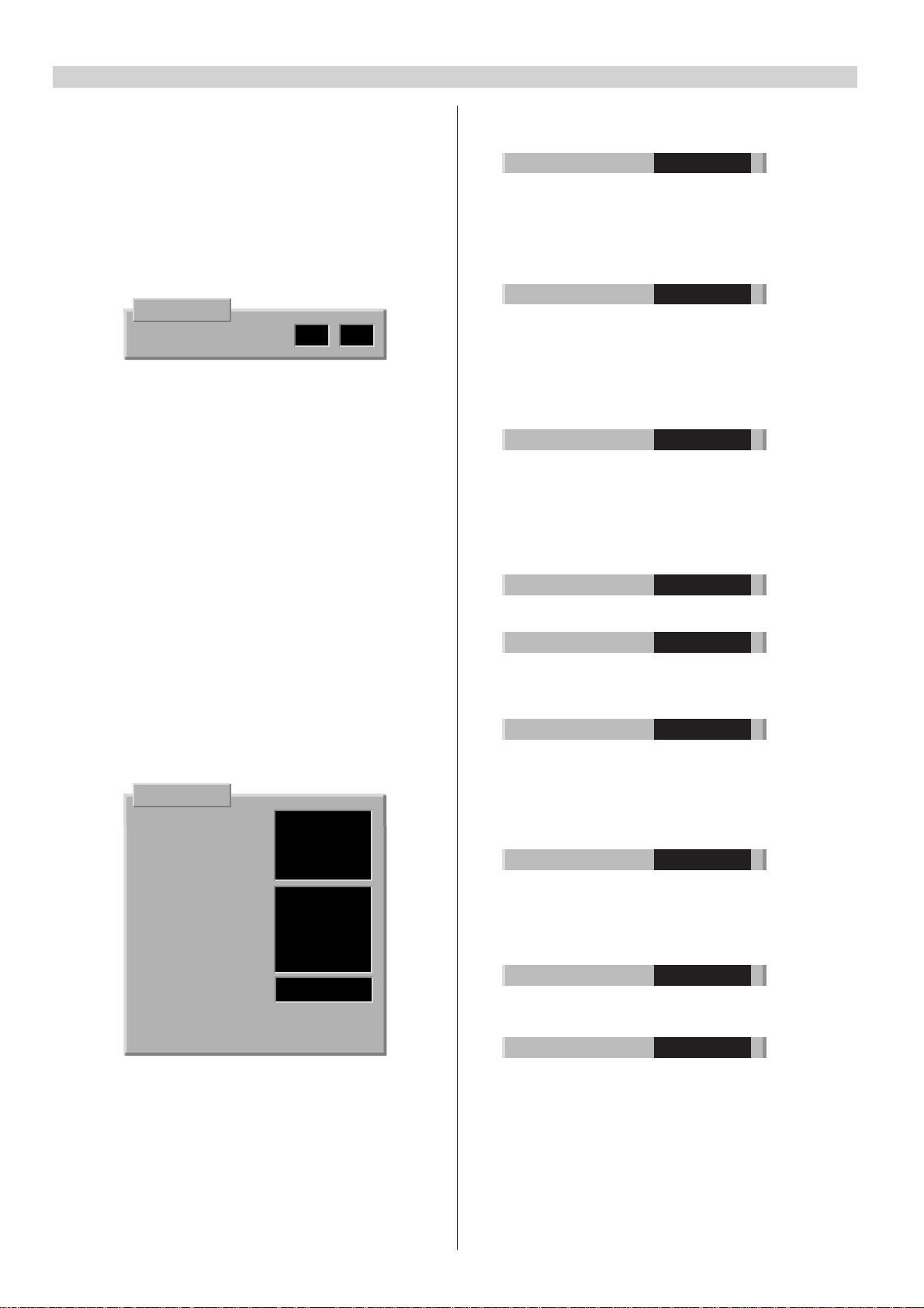
Menu
Timers
Front panel lock
Locking
Tuning
Sort programs
Programme settings
Press ª
Go back
Tuning
Automatic retuning
Add new programs
Manual tuning
External units
Copy tuning to VCR
Copy tuning from VCR
Clear all programs
Press ª
Go back
HIDE
SHOW
ENGLISH
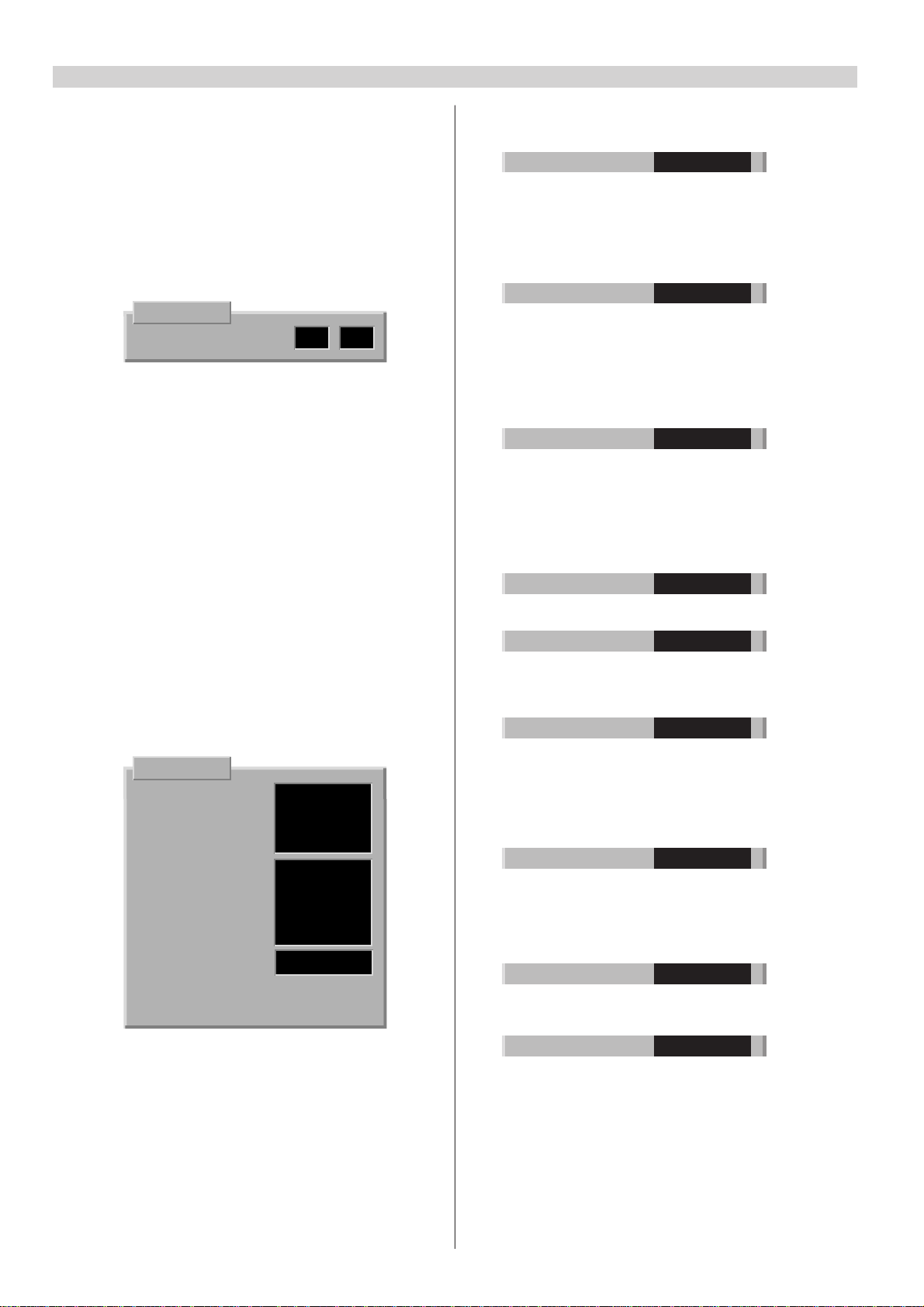
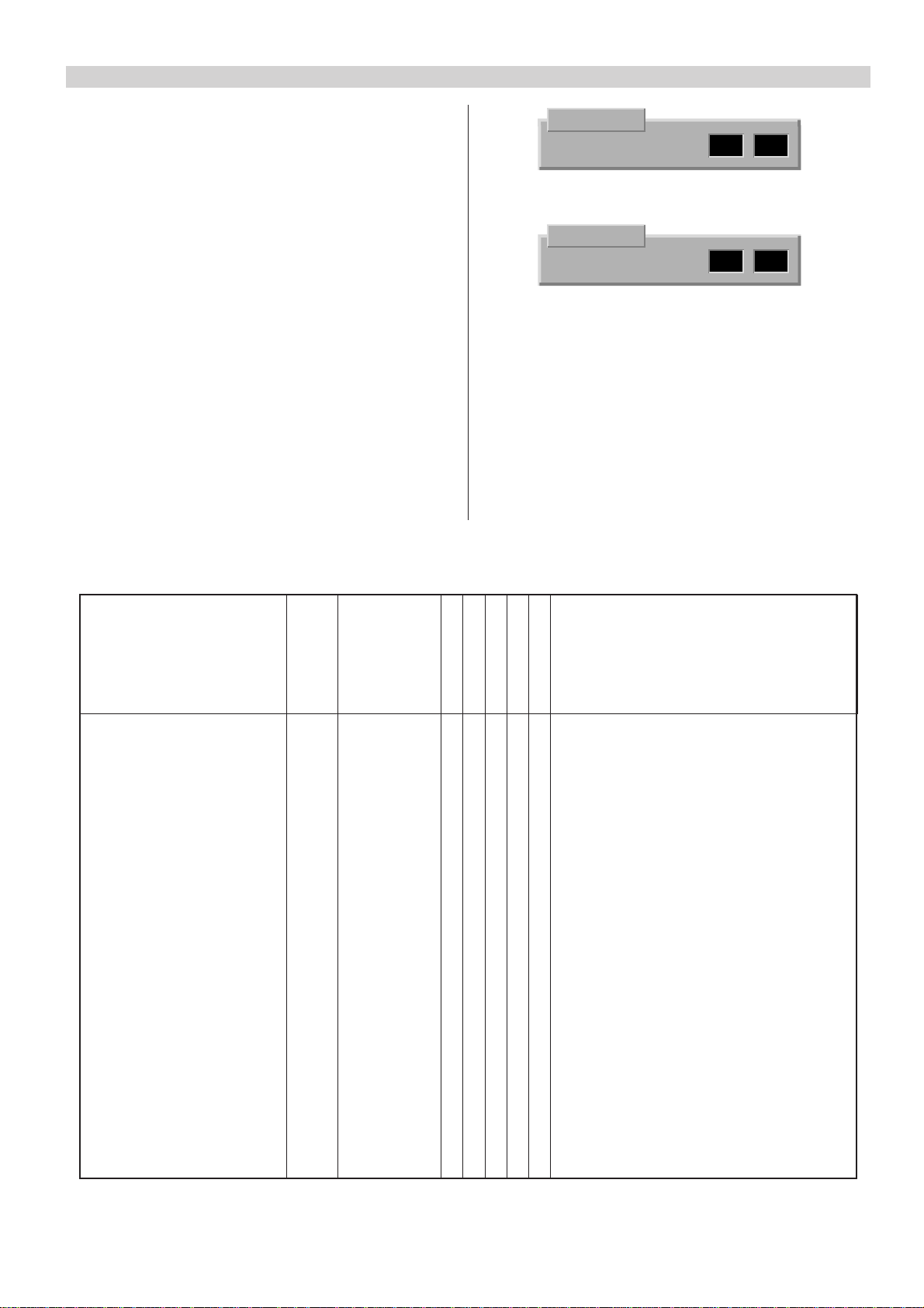
Selecting VGA input
1. Press the MENU button.
2. Select “Tuning” and press the OK button.
3. Select “External units” and press the OK button.
4. Select “VGA computer” and press the TV button.
(If “VGA computer” is not included in the list, select
“Add new unit” by pressing the red button.)
Initialization of NVRAM
Initialization of NVRAM (ICf2)
In case that the NVRAM is replaced, it must be initialized
and configured.
1. Switch the TV set to stand-by mode.
Press e- (volume minus) button on local control unit
and at the same time start entering password: MENU,
TV and i with the remote control. Release e- button
after the MENU button is pressed. The record led will
light up to indicate that service mode is enabled.
2. Press the RED-button to pre-configure the set. Green
led will flash once to indicate this.
3a. At the same time the controller will check NVRAM
and initialize it automatically if it was “empty”.
Initializing will take about 15 s. When it is completed,
the green led will light up. Continue to step 4.
3b.Automatic initialization did not happen if the green
led does not light up steadily. In some cases the led
might also light up immediately after configuration
without any initializing, depending on NVRAM
contents. In this case it might be enough to store the
new configuration by pressing “OK”. Continue to
step 4.
External units
A/V CAMERA
Select E2 VCR
unit VGA COMPUTER
choose from
alternatives
below
Add new Change unit Remove
unit settings unit Go back
3c. If automatic initialization did not happen, you can
start it manually by entering the key code: BLUE (wait
approx. 2 s.), 2, 5, 4 (wait approx. 2 s.) and OK.
Initializing will take about 15 s.
4. Switch off the receiver by pressing the mains switch.
5. Start the receiver in TV mode by pressing the mains
switch. Tune in one or more tv channels.
6. Switch off the receiver with remote control.
7. Enter service mode and make the service adjustments
(see section "SERVICE ADJUSTMENTS VIA I2C BUS").
8. Switch off the receiver by pressing the mains switch.
8
Service adjustments
Service␣ mode␣ selection
1. Switch the TV set to stand-by mode.
2. Press e- (volume minus) button on local control unit
and at the same time start entering password: MENU,
TV and i with remote control. Release e- button after
the MENU button is pressed. The record led will light
up to indicate that service mode is enabled.
3. Switch on the receiver by pressing the TV button twice
and select service mode by pressing the i button.
SERVICE
00 V-AMPL. 38 36
In service mode an adjustment menu is shown on the
screen.The adjustment number and name, initializing
(left) and adjustment (right) values are shown in the
menu.
4. Exit service mode by switching off the receiver with
the mains switch.
Configuration and fault diagnosis
The set must be configured after adding or removing
some options. By pressing the RED button in service
mode, the processor checks the configuration of the TV
set and shows the settings on the screen. The
configuration can be stored by pressing the OK button.
This feature can also be used in fault diagnosis. If an
option bit is not ’1’ when it should be, the IC (or feature)
is either not present or faulty.
Changing the option bytes
1. Select the configuration mode by pressing the RED
button in service mode.
SERVICE
IIC DEV 1 11111001
IIC DEV 2 00000110
IIC DEV 3 00010100
IIC DEV 4 00000001
IF OPT 00000001
TXT OPT 00000001
SYS OPT 1 00111111
SYS OPT 2 00000000
DSP OPT 00000000
UIF FLAGS 00110010
SW VER. MCABxx.x
NVM VER. MCA1-xx
SW VER. = µP software version.
NVM VER. = NVM software version.
2. Select IIC Device byte 1 - 4, Option byte 1 - 5 or uif
flags byte with cursor button (up-/downwards).
Selected byte is shown highlighted.
3. Set the bits with number buttons (0 ... 7).
4. Store the settings by pressing the OK button.
5. Return to normal service mode by pressing the RED
button.
Option byte description
Bit Description ‘1’ ‘0’
76543210
IIC DEV 1 11111001
0 TV tuner Yes No
1 IF Output, HEF4094 Yes No
3 Decoder synch. processor, TDA9143 Yes No
4 Deflection controller, TDA9151 Yes No
5 RGB processor, TDA4780 Yes No
6 IQTV processor Yes No
7 DPLL Yes No
IIC DEV 2 00000110
0 VGA Yes No
1 Main video switch, TDA6417 Yes No
2 Audio processor, MSP3410 Yes No
3 16:9 picture tube Yes No
4 Comb filter Yes No
5 PIP processor, SDA9188 + TDA9141 Yes No
6 PIP tuner Yes No
7 SCART 3 installed Yes No
IIC DEV 3 00010100
0 Virtual sound (3D Sound) Yes No
1 Dolby processor Yes No
2 SDA30C264 processor Yes No
3 Subwoofer Yes No
4 Megatext, SDA5273/75 Yes No
5 External text memory Yes No
6 Level 2.5 Megatext Yes No
7 One field memory (DB711 Module) Yes No
IIC DEV 4 00000001
0 Nicam enabled Yes No
1 Control lead (Xata) to AR7xx module Yes No
IF OPT 00000001
0 B/G system Yes No
1 I system Yes No
2 D/K system Yes No
3 L/L’ system Yes No
TXT OPT 00000001
0 Top enabled Yes No
1 Flof enabled Yes No
2 P26 disabled Yes No
3 Text sync mode Yes No
4 Automatic text subpage rolling Yes No
5 EPG (nexTView) enabled Yes No
6 EPG record enabled Yes No
SYS OPT 1 00111111
0 E0 (A/V connector) installed Yes No
1 E0 S-video Yes No
2 RGB enabled only in E1 Yes No
3 ACI enabled Yes No
4 Micro power supply installed Yes No
5 Carrier mute enabled Yes No
SYS OPT 2 00000000
0 Picture Tilt enabled Yes No
1 Autostart (Hotel TV) Yes No
7 Hotel TV functions enabled (manual) Yes No
UIF FLAGS 00110010
0-2 Logo bit
000 = no logo, go direct to APSi
001 = no logo, go to language menu
010 = Akai logo
011 = Nokia logo
100 = Finlux logo
101 = Salora logo
110 = Luxor logo
3 TV set not used before Yes No
4 Volume bar enabled Yes No
5 On screen programme number enabled Yes No
6 Front panel lock Yes No
7 Off timer active Yes No

Service adjustments via I2C-bus
9
Remote␣ control␣ buttons␣ in␣ service␣ mode
When the receiver is in service mode you can select the
normal TV mode by pressing the TV button and return to
the service mode by pressing the i button.
Number and cursor buttons are used for service
adjustment. The OK button stores the settings.
Adjustment for different picture format
Make all adjustments with PAL signal unless otherwise
mentioned. First make all adjustments with normal 4:3
picture format. Then make the necessary adjustments
with other picture formats/signals. The required
adjustments are shown in the table below.
Note! Check the configuration of the TV set before
making the adjustments and make only the necessary
adjustments.
Making the service adjustment
1. Give a two numbered code which determines the
adjustment (e.g. 06 = width, see the following tables)
with the number buttons. You can also select the
adjustment with cursor buttons (up-/downwards).
Picture geometry adjustments
SERVICE
06 WIDTH 49 33
2. Adjust with cursor buttons (left/right).
SERVICE
06 WIDTH 49 36
3. Store the new value by pressing the OK button.
Note!
• To avoid incomplete adjustments store each
adjustment in the memory immediately after
adjusting.
• If the adjustment has to be made separately for
different picture format/signal, select the normal user
mode by pressing the TV button and select the desired
picture format/signal. Return to service mode by
pressing the i button.
classic (4:3)
wide movie
VGA 60 Hz
VGA 70 Hz
Adjustment Code OSD name Note!
Vertical amplitude 00 V-AMPL. X X X
Vertical off-centre shift 01 V-SHIFT X X
Vertical start scan 02 V-START X X X
Vertical S-correction 03 S-CORR. X X X
Vertical slope (coarse) 04 SLOPE-H X X X Adjust also with NTSC signal.
Vertical slope (fine) 05 SLOPE-L X Adjust also with NTSC signal.
Width 06 WIDTH X X X
Horizontal shift deflection 07 H-SHIFT X Not in all sets.
Horizontal phase video 08 PHASE X X X X
Parabola 09 PARABOLA X X X
Corner 10 CORNER X X X
Trapezium 11 TRAPEZIUM X X
EHT compensation 12 EHT X X Set brightness and contrast to 90% and
RGB
compensate the change in picture size.
VGA 60 Hz = Windows mode
VGA 70 Hz = DOS mode
10
Other adjustments
Adjustment Code OSD name
Red reference 18 R REF.
Green reference 19 G REF.
Blue reference 20 B REF.
Red gain 15 R GAIN
Green gain 16 G GAIN
Blue gain 17 B GAIN
Peak white limit 21 PWL
Luma delay 14 LUMA DELAY
Service adjustments
O Power supply block
Supply voltage and protection circuit
1. Set brightness and contrast to normal level. Connect a
universal voltmeter to the cathode of Do11.
2. Adjust the U1 voltage with Ro45. The voltage depends
on the picture tube type, refer to the section “Variable
components”.
Note!
This procedure is necessary e.g. when the picture tube, CRTmodule etc. has been replaced.
Apply a test picture and adjust the R, G and B references.
Then adjust the R, G and B gains.
Normally no need to adjust.
Separate adjustment for Video, PAL BG, PAL DK/I and Secam L.
K Horizontal deflection block
Horizontal linearity
Adjust with Lk2.
Focusing
Set brightness and contrast to normal level. Use
crosshatch pattern and adjust the picture for optimum
resolution.
3. Check the over-current protection after making any
service operations in the primary circuit of the power
supply. Activate the service mode and then switch the
set to stand-by mode. Short circuit the cathode of
Do13 to the ground and keep the short circuit
connected. When the over-current protection works
correctly, the power supply will try to start 2-3 times
before it stops permanently. Remove the short circuit
and switch on the receiver by pressing the mains
button.
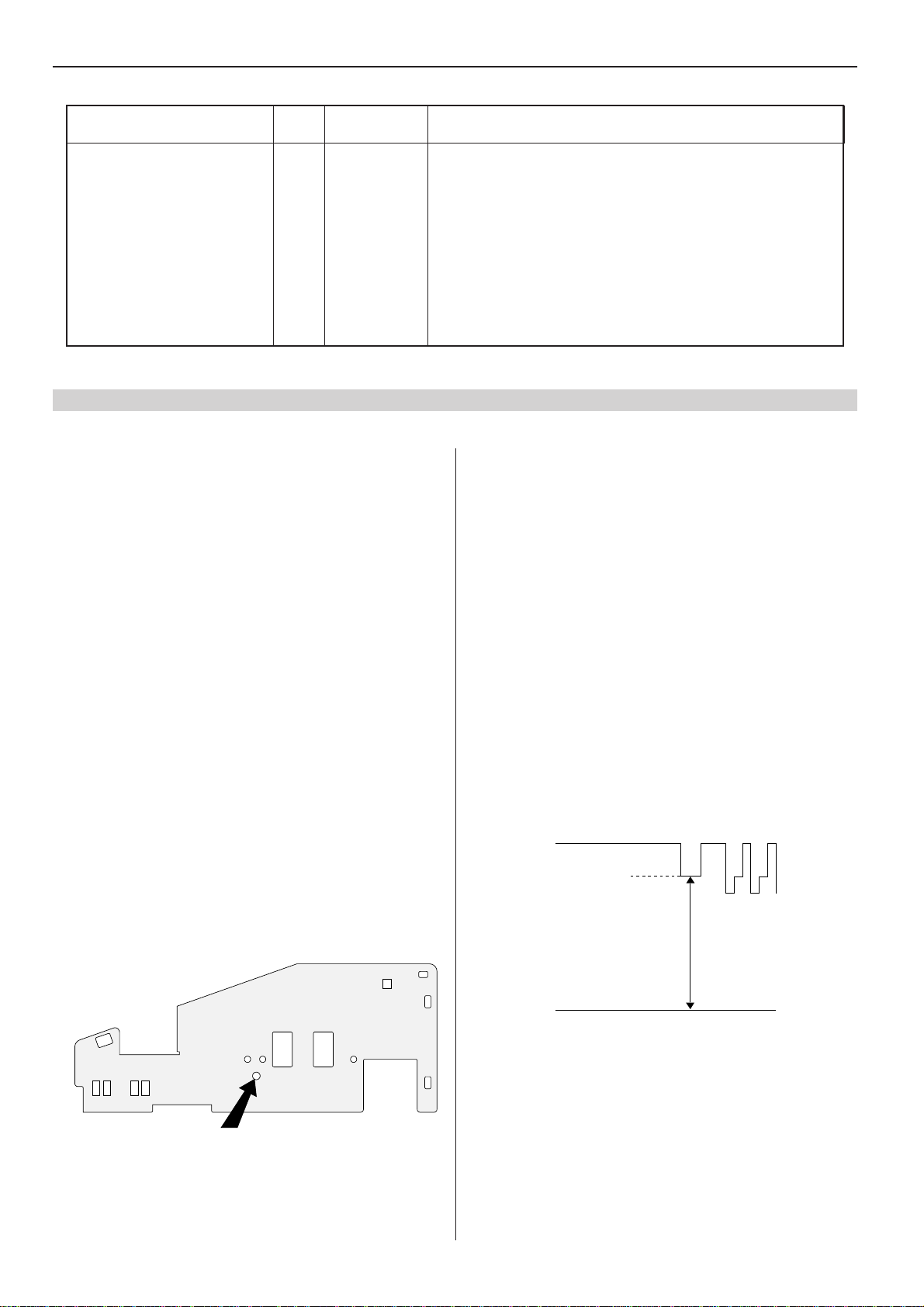
SR Tuner/IF module (Frontend)
Tuner AGC
The tuner AGC is adjusted with a potentiometer through
a hole in the heat sink (see picture below).
Apply a 1 mV (60 dBµV) test signal and adjust the picture
just without noise.
81403760
(Screen grid voltage) Ug2 voltage
1. Set brightness and colour saturation to normal level
and contrast to minimum.
2. At the end of the vertical blanking, there is a black
current measurement pulse (clamp pulse) at pin 9 of
ICh1, ICh2 and ICh3. Use an oscilloscope and find the
output stage with the highest cut-off (i.e. the highest
voltage during the black current measurement pulse).
3. Adjust the voltage of the clamp pulse to +140 V with
Ug2 (see figure).
clamp pulse
140 V
0 V
Note! Adjust the voltage with a clamp pulse.
AGC
Bedienungsanleitung
11
Ändern der Menüsprache
1. Drücken Sie die gelbe Taste zur Wahl des Bildmenüs.
2. Drücken Sie die rote Taste zur Wahl des AnzeigeOptionen-Menüs.
3. Ändern Sie die Menü Sprache mit den Cursortasten.
4. Drücken Sie zum Speichern der Änderungen die OKTaste.
5. Drücken Sie zum Verlassen des Menüs die TV-Taste.
Manuelle Abstimmung
1. Wählen Sie die Programmnummer, die Sie abstimmen
möchten.
2. Drücken Sie die MENU-Taste.
3. Wählen Sie “Abstimmung” und drücken Sie die OK-Taste.
4. Wählen Sie “Senderabstimmung” und drücken Sie die
OK-Taste.
5. Drücken Sie die rote Taste (Kanal-Suchlauf).
6. Drücken Sie zum Speichern die OK-Taste.
7. Drücken Sie zum Verlassen des Menüs die TV-Taste.
APSi (Automatisches Programmiersystem)
1. Drücken Sie die MENU-Taste.
2. Wählen Sie “Abstimmung” und drücken Sie die OK-Taste.
3. Wählen Sie “Neuprogrammierung” und drücken Sie die
OK-Taste.
4. Drücken Sie zur Neuabstimmung der Kanäle die rote
Taste.
5. Drücken Sie zum Verlassen des Menüs die TV-Taste.
Anzeige-Optionen
Programm-Nr.
Lautstärke Balken
Menü Sprache
Bildschärfe
Farbton
Zurück Speichern ª
Menü
Timer
Tasten verriegelt
Verriegeln
Abstimmung
Sortieren
Programmeinstellungen
Drücken Sie ª
Zurück
Abstimmung
Neuprogrammierung
Neue TV-Programme suchen
Senderabstimmung
Externe Geräte
Kopiere Abstimminformation zum VCR
Kopiere Abstimminformation vom VCR
Alle Programme löschen
Drücken Sie ª
Zurück
UNSICHTB.
SICHTBAR
DEUTSCH
Wahl des VGA-Eingangs
1. Drücken Sie die MENU-Taste.
2. Wählen Sie “Abstimmung” und drücken Sie die OK-Taste.
3. Wählen Sie “Externe Geräte” und drücken Sie die OKTaste.
4. Wählen Sie “VGA Computer” und drücken Sie die OKTaste. (Falls “VGA Computer” nicht in der Liste
enthalten ist, wählen Sie “Neues Gerät hinzufügen”
durch Drücken der roten Taste.)
Initialisierung des NVRAM
Initialisierung des NVRAM (ICf2)
Im Falle eines Austausches des NVRAM muß dieser
initialisiert und konfiguriert werden.
1. Schalten Sie das Fernsehgerät in die
Betriebsbereitschaft.
Drücken Sie die e-Taste (Lautstärke-Minus) an der
Bedieneinheit, während Sie gleichzeitig die Eingabe des
Paßwortes mit der Fernbedienung starten: MENU, TV
und i. Lassen Sie die e-Taste los, nachdem die MENUTaste gedrückt wurde. Die Aufnahme-LED leuchtet auf
und zeigt an, daß der Servicemodus aktiviert ist.
2. Drücken Sie zur Vorkonfiguration des Fernsehgerätes
die rote Taste. Die grüne LED leuchtet zur Kontrolle
einmal auf.
3a. Zur gleichen Zeit überprüft der Controller den NVRAM
und initialisiert ihn automatisch, wenn er “leer” war.
Die Initialisierung dauert ungefähr 15 Sekunden. Wenn
sie durchgeführt worden ist, leuchtet die grüne LED auf.
Fahren Sie mit Schritt 4 fort.
3b. Die automatische Initialisierung wurde nicht
durchgeführt, wenn die grüne LED nicht dauernd
aufleuchtet. In manchen Fällen kann die LED direkt nach
Externe Geräte
A/V CAMERA
Wählen Sie das E2 VCR
externe VGA COMPUTER
Geräte aus
Wählen Sie von
untenstehenden
Alternativen
aus
Neues Gerät Einstellung Gerät
hinzufügen verändern entfernen Zurück
der Konfiguration ohne jede Initialisierung aufleuchten,
abhängig vom Inhalt des NVRAM. In diesem Fall ist es
ausreichend, die neue Konfiguration durch Drücken der
OK-Taste zu speichern. Fahren Sie mit Schritt 4 fort.
3c. Ist die automatische Initialisierung nicht durchgeführt
worden, kann diese manuell durch Eingabe des
Schlüsselcodes gestartet werden: BLAUE (ca. 2
Sekunden warten), 2, 5, 4 (ca. 2 Sekunden warten), und
OK. Die Initialisierung dauert ungefähr 15 Sekunden
4. Schalten Sie das Fernsehgerät durch Drücken des
Netzschalters aus.
5. Schalten Sie das Fernsehgerät durch Drücken des
Netzschalters in den Fernsehbetrieb. Stellen Sie einen
oder mehrere Kanäle ein.
6. Schalten Sie das Fernsehgerät mit der Fernbedienung
aus.
7. Gehen Sie in den Servicemodus und nehmen Sie die
Service-Einstellungen vor (siehe Abschnitt “SERVICEEINSTELLUNGEN ÜBER DEN I2C-BUS”).
8. Schalten Sie das Fernsehgerät mit dem Netzschalter
aus.
12
Service-Einstellungen
Wahl des Servicemodus
1. Schalten Sie das Fernsehgerät in die Betriebsbereitschaft.
2. Drücken Sie die e-Taste (Lautstärke-Minus) an der
Bedieneinheit, während Sie gleichzeitig die Eingabe des
Paßwortes mit der Fernbedienung starten: MENU, TV
und i. Lassen Sie die e-Taste los, nachdem die MENUTaste gedrückt wurde. Die Aufnahme-LED leuchtet auf
und zeigt an, daß der Servicemodus aktiviert ist.
3. Schalten Sie das Fernsehgerät durch zweimaliges
Drücken der TV-Taste ein und wählen Sie den
Servicemodus durch Drücken der i-Taste.
SERVICE
00 V-AMPL. 38 36
Im Servicemodus wird ein Einstellmenü auf dem
Bildschirm gezeigt. Die Einstellungszahl und der Name,
die Initialisierung (links) und die Einstellwerte (rechts)
werden in diesem Menü gezeigt.
4. Verlassen Sie den Servicemodus durch Ausschalten
des Fernsehgerätes mit dem Netzschalter.
Konfiguration und Fehlerdiagnose
Nach Hinzufügen oder Entfernen von Optionen muß das
Fernsehgerät konfiguriert werden. Durch Drücken der
roten Taste im Servicemodus überprüft der Prozessor die
Konfiguration des Fernsehgerätes und zeigt die
Einstellungen auf dem Bildschirm an. Die Konfiguration
kann durch Drücken der OK-Taste gespeichert werden.
Dieses Feature kann auch bei der Fehlerdiagnose benutzt
werden. Wenn ein Option-Bit nicht ‘1’ ist - was dieses
aber sein sollte - ist der IC (oder das Feature) entweder
nicht vorhanden oder defekt.
Änderung der Options-Bytes
1. Wählen Sie den Konfigurationsmodus durch Drücken
der roten Taste im Servicemodus.
SERVICE
IIC DEV 1 11111001
IIC DEV 2 00000110
IIC DEV 3 00010100
IIC DEV 4 00000001
IF OPT 00000001
TXT OPT 00000001
SYS OPT 1 00111111
SYS OPT 2 00000000
DSP OPT 00000000
UIF FLAGS 00110010
SW VER. MCABxx.x
NVM VER. MCA1-xx
SW VER. = µP Softwareversion.
NVM VER. = NVM Softwareversion.
2. Wählen Sie das IIC-Gerätebyte 1 -4, das Prüfbyte 1 - 5
oder das uif-Kennzeichenbyte mit den Cursortasten
(auf-/abwärts). Das gewählte Byte wird hervorgehoben
dargestellt.
3. Stellen Sie die Bits mit den Zifferntasten (0 ... 7) ein.
4. Speichern Sie die Einstellungen durch Drücken der
OK-Taste.
5. Kehren Sie durch Drücken der roten Taste zum
normalen Servicemodus zurück.
Beschreibungen der Options-Bytes
Bit Beschreibung ´1´ ´0´
76543210
IIC DEV 1 11111001
0 TV-Tuner Ja Nein
1 IF-Ausgang, HEF4094 Ja Nein
3 Synchronprozessor Decoder, TDA9143 Ja Nein
4 Ablenkungssteuerung, TDA9151 Ja Nein
5 RGB-Prozessor, TDA4780 Ja Nein
6 IQTV-Processor Ja Nein
7 DPLL Ja Nein
IIC DEV 2 00000110
0 VGA Option installiert Ja Nein
1 Hauptvideoschalter, TDA6417 Ja Nein
2 Tonprozessor, MSP3410 Ja Nein
3 16:9 Bildröhre Ja Nein
4 Kammfilter installiert Ja Nein
5 PIP-Prozessor, SDA9188 + TDA9141 Ja Nein
6 PIP-Tuner Ja Nein
7 SCART 3 installiert Ja Nein
IIC DEV 3 00010100
0 Virtueller 3D Ton Ja Nein
1 Dolby-Prozessor Ja Nein
2 SDA30C264-Prozessor Ja Nein
3 Subwoofer installiert Ja Nein
4 Megatext, SDA5273/75 Ja Nein
5 VT mit externen RAM Ja Nein
6 Level 2.5 Megatext Ja Nein
7 Einfeld-Speicher (DB711 Modul) Ja Nein
IIC DEV 4 00000001
0 Nicam aktiviert Ja Nein
1 Steuerleitung (Xata) an AR7xx-Modul Ja Nein
IF OPT 00000001
0 B/G-System Ja Nein
1 I-System Ja Nein
2 D/K-System Ja Nein
3 L/L’-System Ja Nein
TXT OPT 00000001
0 Toptext aktiviert Ja Nein
1 Floftext aktiviert Ja Nein
2 TXT packet P26 nicht aktiviert Ja Nein
3 Text-Synchronmodus Ja Nein
4
Autom. Weiterblättern von Textunterseiten
5 EPG (nexTView) aktiviert Ja Nein
6 EPG-Aufnahme aktiviert Ja Nein
Ja Nein
SYS OPT 1 00111111
0 E0 (A/V-Anschluß) installiert Ja Nein
1 E0 S-Video Ja Nein
2 RGB nur möglich bei E1 Ja Nein
3 ACI aktiviert Ja Nein
4 Micro Power Netzteil installiert Ja Nein
5 Tonträger Steuerschaltung Ja Nein
SYS OPT 2 00000000
0 Bilddrehung aktiviert Ja Nein
1 Autostart (Hotel TV) Ja Nein
7 Hotel TV-Funktionen aktiviert (manuell) Ja Nein
UIF FLAGS 00110010
0-2 Logo-Bit
000 = Kein Logo, direkt in das APSi gehen
001 = Kein Logo, in das Sprachmenü gehen
010 = Akai-Logo
011 = Nokia-Logo
100 = Finlux-Logo
101 = Salora-Logo
110 = Luxor-Logo
3 Fernsehgerät zuvor noch nicht benutzt Ja Nein
4 Lautstärkebalken aktiviert Ja Nein
5 Einblendung Programmnummer aktiviert Ja Nein
6 Verriegelung der Tasten am Gerät Ja Nein
7 Off-Timer aktiv Ja Nein
Service-Einstellungen über I2C-bus
13
Tasten der Fernbedienung im Servicemodus
Wenn sich das Fernsehgerät im Servicemodus befindet,
können Sie den normalen Fernsehmodus durch Drücken der
TV-Taste wählen. Sie können durch Drücken der i-Taste zum
Servicemodus zurückkehren. Ziffern- und Cursortasten
werden zur Service-Einstellung benötigt. Die OK-Taste
speichert die Einstellungen.
Einstellungen für ein anderes Bildformat
Wenn nicht anders vermerkt, nehmen Sie alle Einstellungen
mit dem PAL-Signal vor. Führen Sie zuerst alle Einstellungen
mit dem normalen 4:3 Bildformat durch. Führen Sie dann die
notwendigen Einstellungen mit anderen Bildformaten bzw.
Signalen durch. Die erforderlichen Einstellungen werden in
der unten befindlichen Tabelle gezeigt.
Hinweis! Überprüfen Sie die Konfiguration des
Fernsehgerätes, bevor Sie die Einstellungen vornehmen;
nehmen Sie nur die nötigen Einstellungen vor.
Service-Einstellung vornehmen
1. Geben Sie mit den Zifferntasten den zweistelligen Code
ein, der die Einstellung bestimmt (z.B. 06 = Bildbreite,
siehe folgende Tabellen). Sie können die Einstellung auch
mit den Cursortasten wählen (auf-/abwärts).
SERVICE
06 WIDTH 49 33
2. Nehmen Sie die Einstellung mit den Cursortasten
(links/rechts) vor.
SERVICE
06 WIDTH 49 36
3. Speichern Sie den neuen Wert durch Drücken der OKTaste.
Hinweis!
•
Um unvollständige Einstellungen zu vermeiden,
speichern Sie jede Einstellung direkt nach dem
Einstellen ab.
•
Falls die Einstellung getrennt für verschiedene
Bildformate bzw. Signale durchgeführt werden muß,
gehen Sie durch Drücken der TV-Taste in den
normalen Betriebsmodus und wählen Sie das
gewünschte Bildformat bzw. Signal. Gehen Sie durch
Drücken der i-Taste in den Servicemodus zurück.
Einstellungen der Bildgeometrie
OSD
Einstellung Code Bezeichn. Hinweis!
Vertikale Amplitude 00 V-AMPL. X X X
Vertikale Lage 01 V-SHIFT X X
Vertikale Start-Zeile 02 V-START X X X
Vertikale S-Korrektur 03 S-CORR. X X X
Vertikale Steilheit (grob) 04 SLOPE-H X X X Auch mit dem NTSC-Signal einstellen.
Vertikale Steilheit (fein) 05 SLOPE-L X Auch mit dem NTSC-Signal einstellen.
Bildbreite 06 WIDTH X X X
Horizontale Lage der Ablenkung
Horizontale Lage Video 08 PHASE X X X X
07 H-SHIFT X Nicht in allen Geräten.
Classic
Movie (weit)
VGA 60 Hz
VGA 70 Hz
RGB
OW-Kissen 09 PARABOLA X X X
OW-Ecken Korrektur 10 CORNER X X X
OW-Trapez 11 TRAPEZIUM X X
EHT-Kompensation 12 EHT X X Stellen Sie Helligkeit und Kontrast auf 90%
ein und kompensieren Sie die Änderung
der Bildgröße.
VGA 60 Hz = Windows-Modus
VGA 70 Hz = DOS-Modus