

Page 1

Programmes After Market Services
NHP-2 Series Transceivers
Assembly
Issue 1 05/2002 Nokia Corporation
Page 2

NHP-2
Assembly PAMS Technical Documentation
Page 2 Nokia Corporation Issue 1 05/2002
Page 3
NHP-2
PAMS Technical Documentation Assembly
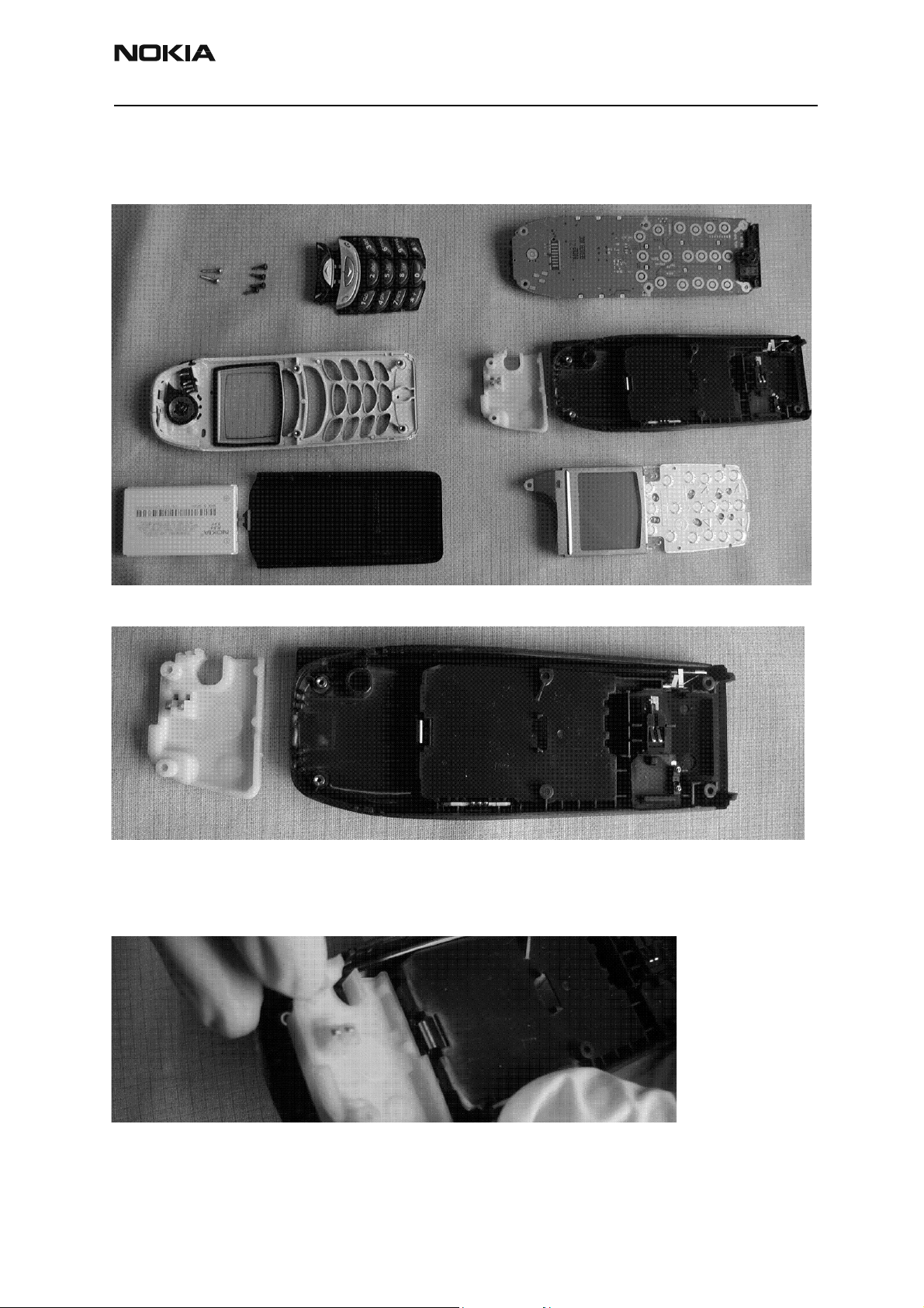
Assembly of the NHP-2
6385 Disassembled to component level
D-cover assembly with the internal antenna
Begin with the D-cover assembly and its components, as shown above.
1. Add antenna.
Grasp the outer edges of the antenna as shown, being careful not to touch any of the
metal-plated contact areas on the antenna. Simply drop the antenna into the opening at
the top of the inside of the D-cover assembly.
Issue 1 05/2002 Nokia Corporation Page 3
Page 4

NHP-2
Assembly PAMS Technical Documentation
D-cover assembly with added components
Shown above is the D-cover assembly, with the antenna attached.
Disassembled PWB/LCD assembly
The next step is to assemble the PWB and LCD assemblies.
2. Add LCD assembly.
To assemble the LCD assembly to the PWB assembly, first align the guide pins with the
holes in the PWB, as shown above. Next, push on the top of the metal frame until the
snaps on the metal frame are engaged.
Page 4 Nokia Corporation Issue 1 05/2002
Page 5

NHP-2
PAMS Technical Documentation Assembly
3. Place the microphone assembly.
Insert the microphone assembly into the system connector at the bottom of the PWB
assembly. The small tab should be oriented toward the lightguide, as shown above. Press
on the top of the microphone assembly to seat the rubber in the cavity.
PWB/LCD assembly
The LCD assembly now is attached to the PWB assembly and the microphone assembly is
in place.
D-cover assembly and PWB assembly
The PWB/LCD assembly now is ready to be installed into the D-cover assembly.
Issue 1 05/2002 Nokia Corporation Page 5
Page 6

NHP-2
Assembly PAMS Technical Documentation
4. Add PWB/LCD assembly to D-cover assembly.
Insert the PWB/LCD assembly into the D-cover assembly by aligning the system connector cutouts with the bottom D-cover bosses.
5. Add screws to the LCD/PWB assembly.
Insert the two 10mm long screws in the top of the phone through the lightguide holes as
shown above. Torque the screws down to the specified torque value (16.9 N-cm or 23.9
in-oz) with a torque-limiting screwdriver or a pre-set pneumatic screwdriver.
Assembled phone without A-cover
Above is the phone with the D-cover, LCD, and PWB assemblies attached.
Page 6 Nokia Corporation Issue 1 05/2002
Page 7

NHP-2
PAMS Technical Documentation Assembly
A-cover side of phone (disassembled)
Shown above is the painted A-cover assembly, keymat assembly, speaker, and speaker
gasket/power key.
6. Add speaker gasket/power key.
Insert the speaker gasket/power key into the A-cover assembly by aligning the power key
portion with the cutout in the IR window on top of the phone. Insert the key into the
hole and then seat the speaker gasket portion onto the ribs in the A-cover.
7. Add speaker.
Insert the speaker into the gasket in the A-cover. DO NOT TOUCH THE SPEAKER SURFACE
OR SPRINGS.
Issue 1 05/2002 Nokia Corporation Page 7
Page 8

NHP-2
Assembly PAMS Technical Documentation
8. Add keymat.
Insert the keymat assembly into the A-cover assembly by aligning the keys in the keyhole
cutouts in the A-cover and slipping it into place.
A-cover assembly with keymat and speaker installed
Shown above is the A-cover assembly with the keymat, speaker, and speaker gasket/
power key installed.
9. Add D-cover side of phone to A-cover side.
While holding the A-cover face up, place the D-cover side of the phone into the A-cover
by aligning the PWB snaps at the bottom of the D-cover with the cutouts in the A-cover.
Press on the top of the phone until a distinctive snap sound is heard, which ensures
proper snap engagement.
Page 8 Nokia Corporation Issue 1 05/2002
Page 9

NHP-2
PAMS Technical Documentation Assembly
10. Add screws to the back of the phone.
Add screws to the backside of the phone in the locations indicated above.
11. Torque down screws.
Torque the screws down to the specified torque value (16.9 N-cm or 23.9 in-oz) with a
torque-limiting screwdriver or a pre-set pneumatic screwdriver.
Issue 1 05/2002 Nokia Corporation Page 9
Page 10

NHP-2
Assembly PAMS Technical Documentation
12. Add battery.
Insert the battery into the battery recess in the back of the phone by first aligning the
pegs in the bottom of the D-cover with the cutouts in the bottom of the battery. Press
the battery firmly into place.
13. Add battery cover.
Insert the battery cover onto the back of the phone to where the tab at the top is just
below the cutout in the D-cover. While applying pressure, push the battery cover upward
until the locking features snap into place.
Page 10 Nokia Corporation Issue 1 05/2002
 Loading...