

Page 1

After Sales Technical Documentation
NHA–2/4 SERVICE
SOFTWARE
INSTRUCTIONS
Original, 33/96
NMP Part No. 0275101
Page 2

Service Software Instructions for NHA–2 and NHA–4
AMENDMENT RECORD SHEET
After Sales
Technical Documentation
Amendment
Number
Date Inserted By Comments
Page 2
Original, 33/96
Page 3

After Sales
Technical Documentation
Service Software Instructions for NHA–2 and NHA–4
NHA–2/4 SERVICE SOFTWARE INSTRUCTIONS
Contents
Introduction Page 5
General Page 5
Required Servicing Equipment Page 5
Mechanical Connections Page 6
Start Up Procedure Page 7
Service Software Menu Structure Page 8
Using Menus Page 9
Menu Bar Page 9
Windows Page 10
Dialog Boxes Page 11
File Selection Dialog Box Page 12
Service Software Menu Functions Overview Page 13
File Menu Page 13
Open Page 13
Save Page 13
Save As Page 13
Edit Page 14
Exit Page 14
Tuning Menu Page 15
Initialize Local Mode Page 15
Battery Reference Page 15
Reference Charge Voltage Page 15
VCO Page 15
VCXO Page 15
TX Power Level Tuning Page 15
Deviation Tuning Page 15
RSSI Reference Value Page 15
Tuning Values Page 16
Testing Menu Page 16
Phone Mode – Local/System Page 16
Initialize Local Mode Page 16
Quick Testing/Setup Page 16
Audio Controls Page 17
Signalling Control Page 17
RX & TX VCO Checking Page 18
ADC Reading Page 18
Display Test and Light Control Page 19
Original, 33/96
Page 3
Page 4

Service Software Instructions for NHA–2 and NHA–4
Reading Error Codes Page 19
SINAD & XEAR level Page 20
Dealer Menu Page 21
Subscriber (NAM) Data Page 21
Short Code Memory Page 24
NAM1 SID Screening / NAM2 SID Screening Page 25
User Menu Settings Page 26
Phone Identification Page 26
Warranty Information Page 27
Help Menu Page 27
After Sales
Technical Documentation
Page 4
Original, 33/96
Page 5

After Sales
Technical Documentation
Service Software Instructions for NHA–2 and NHA–4
Introduction
General
The Service Software is specially designed to facilitate the servicing of fifth
generation cellular telephones.
The software can be used to control the phone according to the user’s requirements merely by entering commands via the keyboard / mouse of a PC connected to the phone.
This section refers to AMPS Service Software Version 1.00. NMP After Sales
will notify service personnel about future upgrades via Technical Bulletins. Software upgrades will be available from your local NMP outlet.
Required Servicing Equipment
– Computer: IBM PC / AT or compatible with one unused serial port (COM1 or
COM2*), one parallel port (LPT1), hard disk recommended.
– Operating System: DOS Version 3.3 or later
– 500 kB free memory under DOS
– Display: Any 80–character text display
– PC Locals program: LSA–3K (product code 0193697) for 3.5” disk or
LSA–3L (product code 0193698) for 5.25” disk.
– Software Protection Key PKD–1 (product code 0750018)
– M2BUS interface cable DAU–4S (product code 0730057)
*)
Note: A number of PC’s of an older generation use the Intel, National Semiconductor, or
Original, 33/96
United Microelectronics IC 8250 as the serial port UART. This is a comparatively
inefficient circuit for current purposes and does not necessarily support the
M2BUS adapter at 9600 baud. The newer UART’s NS16450 and NS16550AF of
National Semiconductor offer solutions for these problems.
Page 5
Page 6

Service Software Instructions for NHA–2 and NHA–4
Mechanical Connections
Caution: Ensure that you have switched off the PC and the printer before
making connections !
Caution: Do not connect the PKD–1 to the serial port. This could damage
the PKD–1 !
The software controls the phone via a separate adapter connected to the serial
port of the PC and to the telephone’s M2BUS (DAU–4S and XCM–1).
Attach the protection key PKD–1 to parallel port one (25–pin female D–connector) of the PC. When connecting the PKD–1 to the parallel port be sure that you
insert the PC end of the PKD–1 to the PC (male side). If you use a printer on
parallel port one, place the PKD–1 between the PC and your printer cable.
The PKD–1 should not effect devices working with it. If some errors occur (errors in printing are possible) please try printing without the PKD–1. If printing is
OK without the PKD–1 please contact your dealer. We will offer you a new
PKD–1 in exchange for your old one.
After Sales
Technical Documentation
Page 6
Original, 33/96
Page 7

After Sales
Technical Documentation
Attach one end of the M2BUS interface cable, DAU–4S (2), to the PC serial
port and the other end to the bottom connector of the phone.
Service Software Instructions for NHA–2 and NHA–4
Start Up Procedure
Start the phone by pressing the power–on button of the handset. Switch PC
power on.
To start the software on diskette, proceed as follows:
1. Insert service software disk into
drive A of your PC
2. Log into drive A: type
3. Start service software: write
To start the software on hard disk (if installed), proceed as follows:
1. Log into drive C: type
2. Start service software: write
Note: Type
The service software starts by loading the configuration file. After it has been
loaded, a menu bar is shown at the top line of the display. Refer to section ”Using Menus” for how to proceed through the menus. In the middle of the display
will be a Phone Identification Window which displays some basic information
about the connected phone.
NHA2SERV /? + Enter
A:
and press
NHA2SERV
C:
and press
NHA2SERV
if you want see all starting options.
Enter
and press
Enter
and press
Enter
Enter
Press
Original, 33/96
Enter
to close the Phone Identification Window.
Page 7
Page 8
Service Software Instructions for NHA–2 and NHA–4
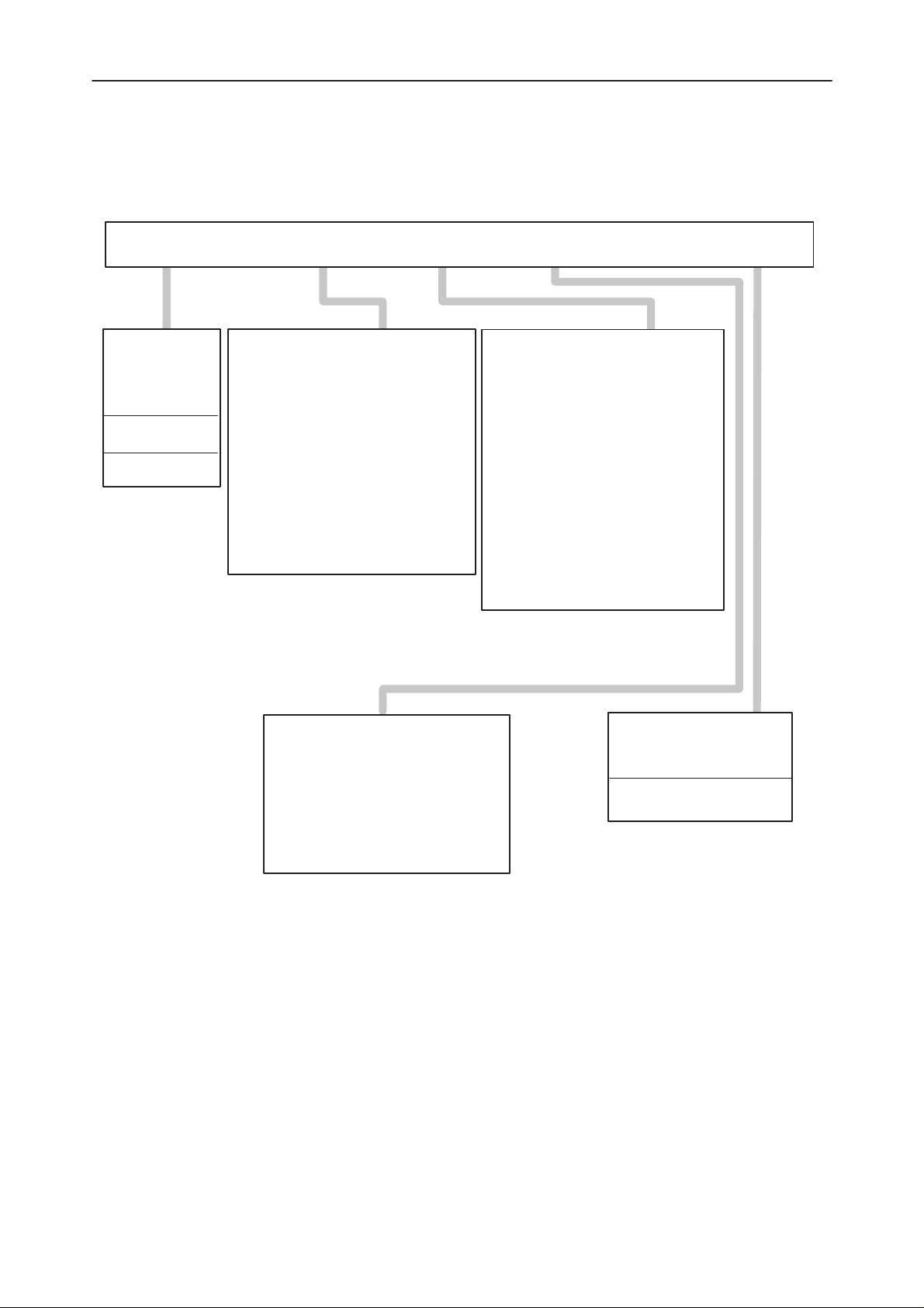
Service Software Menu Structure
TuningFile Testing Dealer Help
After Sales
Technical Documentation
Open
Save
Save As
Edit
Exit Alt–X
Initialize Local Mode
Battery Reference
Reference Charge Voltage
VCO
VCXO
TX Power Level Tuning
Deviation Tuning
RSSI Reference
Tuning Values
Subscriber (NAM) Data
Short Code Memory
SID Screening
User Menu Settings
Phone Identification
Warranty Information
Phone Mode Local/System
Initialize Local Mode
Quick Testing / Setup
Audio Controls
Signaling Control
RX & TX VCO Checking
ADC Reading
Display Test / Light Control
Reading Error Codes
Sinad & Xear Level
General Help F1
Using Help
Product Information
Page 8
Original, 33/96
Page 9

After Sales
Technical Documentation
Using Menus
There are three visible components to service software: the menu bar at the
top, the window area in the middle, and the status line at the bottom of the
screen. Many menu items also offer dialog boxes. Although there are several
different ways to make a selection in service software, they access the same
commands and dialog boxes.
Menu Bar
The menu bar is the primary access to all the menu commands.
Here is how you choose menu commands using the keyboard:
Service Software Instructions for NHA–2 and NHA–4
– Press
the items on the menu bar.
– Use the ← → arrow keys to select the menu you wish to display and then
press
ter of the menu title. For example, when the menu bar is active, press F to
move to and display the File menu. At any time press
letter (e.g.
– Use the ↑
and press
menu command.
At this point service software either carries out the command, displays a dialog
box, or displays another menu.
There are two ways to choose commands with a mouse:
– Click the desired menu title to display the menu and click the desired com-
mand.
– Drag straight from the menu title down to the menu command. Release the
mouse button on the command you want. If you change your mind, just
drag off the menu; no command will be chosen.
Service software offers a number of quick ways to choose menu commands.
The click–drag method for mouse users is an example. From the keyboard, you
can use a number of keyboard shortcuts (or ’hotkeys’) to access the menu bar,
choose commands or work with dialog boxes. You need to hold down
pressing the highlighted letter when moving from input box to a group of buttons or boxes.
F10
to make the menu bar active; the next thing you type will relate to
Enter
. As a shortcut to this step you can just select the highlighted let-
Alt
and the highlighted
Alt
+ F) to display the menu you want.
↓ arrow keys to select command from the menu you have opened
Enter
. As a shortcut you can just press the highlighted letter of the
Alt
while
Original, 33/96
Page 9
Page 10

Service Software Instructions for NHA–2 and NHA–4
Windows
Some of the actions you see and do in Service Software happens in a window.
A window is a screen area that you can open, close, and move.
Most of the windows have these things in common:
– a title bar
– a close box
The following figure shows a typical window:
After Sales
Technical Documentation
The close box of a window is the box in the upper left corner. Click this box to
quickly close the window.
The title bar, the uppermost horizontal bar of a window, contains the name of
the window. You can drag the title bar to move the window around.
Page 10
Original, 33/96
Page 11

After Sales
Technical Documentation
Dialog Boxes
Most of the menu commands lead to a dialog box. Dialog boxes offer a convenient way to view and set multiple options. They are typically used for making
settings or performing some action where the phone must be in a certain state
and all other actions must be denied. When you are making settings in a dialog
box, you work with five basic types of on–screen control:
– action buttons
– radio buttons
– check boxes
– input boxes
– list boxes
Dialog boxes also have similar features to windows; title bar and close box. Below is a sample box which lists some of these features:
Service Software Instructions for NHA–2 and NHA–4
This dialog box has two standard buttons:
the choices in the dialog box are accepted. If you choose
and the dialog box is exited.
log box.
If you are using a mouse, click the dialog–box button you want. When you are
using the keyboard, press
Press
box. Each element is highlighted when it becomes active.
Radio buttons are like car–radio buttons. They arranged in groups, and only
one radio button in a group can be selected at any one time. To choose a radio
button, click it or its text. From the keyboard, select
or press
choose a particular radio button. Press
new radio button chosen.
Original, 33/96
Enter
and
Esc
. If you choose
Esc
, nothing changes
Esc
is always a keyboard shortcut to exit the dia-
Alt
and the highlighted letter of an item to activate it.
Tab
to move forwards or backwards from one item to another in a dialog
Alt
and the highlighted letter
Tab
until the group is highlighted, and then use the arrow keys to
Tab
again to leave the group with the
Enter
Page 11
,
Page 12

Service Software Instructions for NHA–2 and NHA–4
Check boxes differ from radio buttons in that you can have any number of
check boxes checked at any time. When you select a check box an X appears
in it to show you it is on. An empty box indicates it is off. To change the status
of a check box, click it or its text, press
and then press the
If several boxes apply to a topic, they appear as a group. In this case tabbing
moves to the group. Once the group is selected use the arrow keys to select
the item you want and then press
Input boxes let you type in text. Most basic text–editing keys work in the text
box (for example arrow keys,
tents of the input box are highlighted (typically when you first select it) and you
start typing in new data, the old data is erased.
A final component of some dialog–boxes is a list box, which lets you scroll
through and select from variable length lists without leaving a dialog box. You
make list box active by clicking it or by choosing the highlighted letter of the list
title (or press
use the scroll box to move through the list or press the up or down arrow from
the keyboard.
Spacebar
or select
Home, End, Backspace, Del
Tab
until it is highlighted). Once a list box is displayed, you can
Tab
Alt
Spacebar
After Sales
Technical Documentation
until the check box is highlighted
plus the highlighted letter.
to check or uncheck it.
and
Ins
). If the con-
File Selection Dialog Box
The File–Selection box offers you a way to select the file you want to open
for reading or writing. Below is an example of such a box:
Page 12
Figure 1.
Original, 33/96
Page 13

After Sales
Technical Documentation
Service Software Instructions for NHA–2 and NHA–4
Service Software Menu Functions Overview
The Service Software is divided into 5 main blocks: File, Tuning, Testing, Dealer, and Help.
File is used to save all parameters to a configuration file to enable set up as required. It is possible to change the PC settings to a configuration file as well as
the default parameters of the phone such as channel number, transmitter on/
off, audio settings, etc. It is also used to edit default settings for NAM information and SID screening information.
Tuning contains the functions required for tuning the phone.
Testing contains the functions required for testing the phone in Local mode.
Dealer is used to edit all NAM and other user information. It also contains user
data transfer programs to be used in case a faulty phone should be replaced
with a new unit.
Faultlog menu contains information about the repaired phone.
Help contains all the help information for using Service Software.
File Menu
The file menu contains commands related to file operations. It lets you save
and edit configuration files and also exit Service Software.
Open
The File/Open command displays a File–Selection dialog box for you to select
a configuration file to open. These files contain Local mode setup. You can edit
these values with File/Edit command. Once the file is opened the new values
take effect.
Save
The File/Save command saves the previously opened configuration file. If no
file has been opened, Save As command is performed instead.
Save As
The File/Save As command lets you save the configuration file under a different
name, in a different directory or under a different drive. When you choose this
command you will see the File–Selection dialog box for Save File As.
Original, 33/96
Page 13
Page 14

Service Software Instructions for NHA–2 and NHA–4
Edit
The File/Edit command opens a dialog box for editing the configuration file contents. A dialog box would look like the following example:
After Sales
Technical Documentation
Exit
At the top of the dialog box you can see the name of the current configuration
file. Below that are default Testing/Local mode settings. Select the value you
Alt
want to change using ’hotkeys’ (
ulator keys, and then type in the new value. Accept the changes by pressing
Enter
or abandon by pressing
The File/Exit command exits Service Software. Before exiting a confirmation
box is
displayed. Pressing
Enter
quits the program and
+ letter), clicking with a mouse, or using tab-
Esc
(or click the corresponding button).
Esc
cancels exiting.
Page 14
Original, 33/96
Page 15

After Sales
Technical Documentation
Tuning Menu
This menu contains the commands needed for tuning the phone. Choosing tuning opens up a sub–menu from where the desired tuning can be selected. After
you select a tuning from the sub–menu, a tuning dialog box will be opened, and
all necessary settings for the phone will be done automatically.
Note: Service technicians are strongly advised to use the separate service
instructions booklet when tuning the handportables.
Note: If you wish to only view and not change the tuning parameters, press
Esc to exit the screen.
Initialize Local Mode
This command reactivates the locals mode of the phone.
Battery Reference
Service Software Instructions for NHA–2 and NHA–4
This consists of tuning the reference value for the battery.
Reference Charge Voltage
This consists of tuning the reference charge voltage.
VCO
This command is used to tune the VCO of the phone.
VCXO
This command is used to tune the VCXO frequency of the phone.
TX Power Level Tuning
This command is used to tune the phone’s TX power levels. When selected,
the transmitter will be switched on at power level 7 on middle channel (default:
channel 380).
Deviation Tuning
A number of deviation tunings are grouped together in this command. They are,
however, still tuned independently of each other.
RSSI Reference Value
This consists of tuning the reference value for the RSSI meter. It is carried
out without an external signal using noise.
Original, 33/96
Page 15
Page 16

Service Software Instructions for NHA–2 and NHA–4
Tuning Values
With this command you can save the read Tuning Data from the EEPROM, and
save factory default tuning values to phone. You can read/save those values
from/to file as well.
Testing Menu
The Testing Menu allows the Service Technician to switch a phone to Local
mode in order to attempt to simulate a reported fault or configure a phone to
test a certain parameter. It allows the technician complete control over internal
and external audio, and the RF settings.
When Testing is selected, the phone is placed into Service mode automatically.
This is known as Local mode. Unless the user changes this configuration, using File, the phone receiver is tuned to Channel 380; the Transmitter synthesizer is also tuned to Channel 380 but with the PA switched off.
After Sales
Technical Documentation
Phone Mode – Local/System
This allows you to change from Local Mode to normal System Mode and back
to Local Mode.
Initialize Local Mode
This allows the phone to be reset into Local mode. The text ’Local’ will appear
in the phone’s display.
Quick Testing/Setup
This command opens a Window allowing the user full control over the channel
the phone is tuned to; the transmit power state; and access to some simple audio routing and signal switching.
Page 16
Original, 33/96
Page 17

After Sales
Technical Documentation
Audio Controls
This command allows you to test all possible audio paths in and out of the audio processing device including XMIC, XEAR and DTMF.
Service Software Instructions for NHA–2 and NHA–4
Signalling Control
This command allows the setting of the following signalling parameters. The *
symbol in each column indicates the phone’s present state.
Original, 33/96
Page 17
Page 18

Service Software Instructions for NHA–2 and NHA–4
RX & TX VCO Checking
This command will check that RX VCO and TX VCO synthesizers will lock
across the required bandwidth.
ADC Reading
After Sales
Technical Documentation
This displays a table showing the following readings of the A/D converters.
Item: Name: Function:
0 VBATSW Battery voltage
1 CHRGMON Charge voltage
2 BTEMP Battery temperature
3 BSI Battery size indication
4 RSSI Received Signal Strength
5 TXI Transmit power monitor
6 RFTEMP RF temperature
7 XMIC External microphone line state
Page 18
Original, 33/96
Page 19

After Sales
Technical Documentation
Display Test and Light Control
This enables checking of the operation of the display segments and the phone
back–lighting.
Service Software Instructions for NHA–2 and NHA–4
Display Test:
– Clear Display
– Fill pattern 1 switches on all icons and fills alphanumeric area with a pattern
– Fill with pattern 2 switches on all icons and fills alphanumeric area with
a different pattern
– Fill with pattern 3 switches on all icons and fills alphanumeric area with
a different pattern
Lights:
– On switches on all back–lighting
– Off switches off all back–lighting
Reading Error Codes
This command is used to read error codes from phone. The following error
codes are possible:
– No Error Detected
– Error in EEPROM id field
– Error in EEPROM RF tuning parameters
– Error in EEPROM audio tuning parameters
– Error in EEPROM device/charge tuning parameters
– Error in checking the serial number
– Error in checking modem circuit
– Error in checking audio circuit
– Invalid Error Code Received
Original, 33/96
Page 19
Page 20

Service Software Instructions for NHA–2 and NHA–4
SINAD & XEAR level
This command is used to test SINAD and XEAR level.
Measure RX SINAD
– Connect an RF SIGNAL GENERATOR to the phones antenna connector
and set up the instrument as follows:
• FREQUENCY to RX frequency of the current middle channel
• OUTPUT LEVEL: –116 dBm.
• MODULATING FREQUENCY: 1 kHz.
• DEVIATION: 8.0 kHz.
– Connect a SINAD meter to the XEAR output of the phone and check that the
Psophometrically weighted SINAD measured is greater than 12 dB.
Measure XEAR:
– Increase the RF signal level to –50 dBm and change the deviation to
2.3 kHz.
After Sales
Technical Documentation
– Now check that the audio signal level measured at XEAR is in the range of
35...70 mV
RMS
.
Page 20
Original, 33/96
Page 21

After Sales
Technical Documentation
Dealer Menu
Selecting Dealer will bring up a sub–menu as shown below:
– Subscriber (NAM) data
– Short code memory
– User menu settings
– User data transfer
– Phone identification
– Warranty information
Note: If NAM password differs from factory password it is asked when
entering subscriber data, user data transfer or warranty information
menu items.
Subscriber (NAM) Data
Service Software Instructions for NHA–2 and NHA–4
This can be used to program all the Subscriber Data and Common NAM Data
information into a telephone. This can also be programmed through the
phone’s keypad.
Note: If you wish to only view and not change the NAM information,
press Esc to exit the screen.
Any NAM in the phone can be read from/written to by selecting either 1 or 2.
When a selection is made, all the NAM information displayed on the PC is updated. Basic information displayed next to 1/2 is operator name (if the phone
has been programmed using the customization feature), and Subscriber Number (MIN–P).
From this example it can be seen that NAM 1 has been programmed. The ESN
of the phone is also clearly displayed.
Original, 33/96
Page 21
Page 22

Service Software Instructions for NHA–2 and NHA–4
Dealers are strongly advised to use the customisation feature. For any operator
they could store, as a default, the following parameters:
Home System Identification (SIDH)
– This number is used to define the primary traffic area of the phone. The
number contains the country code, system bit information and the area
code.
Local Use Mark
– This option is used to determine whether the phone must respond to local
control messages sent from the exchange.
Access Method (EX)
– This is used to define the method of sending the phone identification data
(x = country code in use).
Initial Paging Channel (IPCH)
– This number is used to identify the primary traffic channel of the phone. Typ-
ically 333 for system A and 334 for system B.
After Sales
Technical Documentation
Access Overload Class (ACCOLC)
– This number is used to identify which overload class the phone belongs to.
Numbers 0–9 corresponds to normal phone class (typically 0 + last digit of
MIN).
Group Identification Mark (GIM)
– This is used to identify the group of the phone.
Purchasing Date
– Purchasing date is used for warranty purposes. This location should be pro-
grammed when the phone is delivered to the customer. This location can be
programmed only once, when the contents of the location is 0000. After it is
programmed, it can be read but not changed any more.
You are also able to store:
Language
– Four languages can be selected (English, French, Spanish and Portu-
guese).
Emergency Numbers
– A few emergency numbers can be defined.
Page 22
Lock Code
– A four digit individual lock code can be defined.
Wake Up Message
– This option enables defining for example the name of the phone owner into
the power up display. If the name is not entered here, the subscriber’s num-
ber is shown.
Original, 33/96
Page 23

After Sales
Technical Documentation
NAM Programming
The process for programming a NAM with this method is as follows:
1. Select NAM 1 or 2
2. Select Operator – scroll through the available defaults using the arrow keys
until you find the desired default. All the default information will be displayed
on the PC screen
3. Select Number and program the new subscriber number using the normal
text editing keys
4. Select Wake up and program the new Wake up message using the normal
text editing keys. To help with the message alignment, the phone’s display
will constantly be updated during this process
5. Select lock and program the new lock code using the normal text
editing keys
6. Select
Enter
Service Software Instructions for NHA–2 and NHA–4
to save to EEPROM.
Alternatively, the user is able to program each individual parameter if they
choose not to use the customization feature.
Original, 33/96
Page 23
Page 24

Service Software Instructions for NHA–2 and NHA–4
Short Code Memory
Selecting Dealer/Short Code Memory opens the short code memory dialog box.
In this box, you can view and edit all memory locations of the phone. You can
also store the information to a file and read information from a file. It is also
possible to read short code memory files generated by other product’s service
software. The following Service Software supports this general file format.
The SCM editing dialog box is shown below:
After Sales
Technical Documentation
In the editing dialog box, edit or type in a new name and number. You can
change the field with the
plete you are able to accept the new values and return to the full SCM dialog
box by pressing
the operation.
In the SCM dialog box the following command buttons are available:
File Load (
File Save (
Read Phone (
Write Phone (
Esc–Close Closes the SCM programming dialog box. Click the button
Alt+L
Alt+S
Enter
) Reads SCM data from a file. You can select a file to be
) Writes SCM data to a file. You can select the file to write
Alt+R
Alt+W
Tab
key or clicking with a mouse. When this is com-
or by clicking the corresponding button.
loaded from the File selection dialog box.
to from the File selection dialog box.
) Reads SCM data from the phone and updates it to the
display.
) Writes SCM data to the phone. Before writing, the user is
asked to confirm the writing.
Esc
or press the
key.
Esc
will cancel
Page 24
Original, 33/96
Page 25

After Sales
Technical Documentation
Service Software Instructions for NHA–2 and NHA–4
NAM1 SID Screening / NAM2 SID Screening
Selecting Dealer/NAM1/2 SID screening opens a SID screening dialog box. In
this box you can edit at maximum 32 SIDs (friendly/unfriendly) of the phone for
both NAM1 and NAM2. You can also store the information to a file and read information from file.
The SID editing dialog box is shown below:
In the editing dialog box, edit or type in new SID (friendly/unfriendly). Friendly
SID begins with a ‘*‘ character. Unfriendly SID begins with ‘#‘ character.
Explanations:
If SID screening is activated from menu of the phone, the phone will not accept
channels of an unfriendly network. Only emergency calls are available in unfriendly network. The call is made in neutral network (not in SID screening list)
only if friendly network is not available.
When this is complete you are able to accept the new values and return the full
SID dialog by pressing ENTER or by clicking the corresponding button. ESC
will cancel the operation.
In the SID dialog box, the following command buttons are available:
File Load (ALT+L) Reads SID data from file. You can select a file
to be loaded from the File selection dialog box.
File Save (ALT+S) Writes SID data to file. You can select the file to
write to from the File selection dialog box.
Read Phone (ALT+R) Reads SID data from the phone and updates it
to the display
Write Phone (ALT+W) Writes SID data to the phone. Before writing
ESC–Close Closes the SID programming dialog box. Click
Original, 33/96
the user is asked to confirm the writing.
the button or press ESC key.
Page 25
Page 26

Service Software Instructions for NHA–2 and NHA–4
User Menu Settings
By selecting Dealer/User Menu Settings you can view and change the following
User Menu parameters:
– Lights
– Ring Volume
– Keypad Tones
– Ring Type
– Emergency
– One Touch Call
– Call Restrictions
After Sales
Technical Documentation
You can move between these groups by using the
setting using the arrow keys. Alternatively, you can click on the desired value
with the mouse. Press
mouse to save the new settings to the EEPROM or press
box without altering the original values.
Phone Identification
By selecting this option you can see phone type and version.
Tab
key and select a new
Enter
or click on the corresponding button with the
Esc
to exit the dialog
Page 26
Original, 33/96
Page 27

After Sales
Technical Documentation
Warranty Information
NOTE! Command Warranty Information contains also editing repair month
though it is not transferred to other phone.
If phone is not Warranty Defective Phone, command asks if repair month is
edited or warranty information transferred.
If phone is warranty defective phone, command automatically activates repair
month editing.
1)
Warranty Information contains contents of NAM (except NAM password),
Short Code Memory, User Menu Settings, manufacturing month, purchasing
month and warranty serial number.
Warranty serial number of exchange phone is:
a)
serial number of original phone if warranty serial number of original
phone is empty.
b)
warranty serial number of original phone if warranty serial number of
original phone is NOT empty.
Service Software Instructions for NHA–2 and NHA–4
2)
Original phone will be made warranty defective phone when warranty
information is transferred.
3)
Warranty information will not be transferred to other phone if
a)
automatically to ’edit repair month’ mode)
b)
c)
NOTE! In cases b) and c) you must immediately return the original phone
Help Menu
Choose Help/Using Help to obtain information on how to use the help facilities.
Original phone is warranty defective phone (command goes
NAM password of original phone differs from that of exchange phone.
Exchange phone is warranty defective phone.
to jig, to avoid making it to warranty defective phone!
Original, 33/96
Page 27
Page 28

Service Software Instructions for NHA–2 and NHA–4
After Sales
Technical Documentation
This page intentionally left blank.
Page 28
Original, 33/96
 Loading...