

Page 1

CCS Technical Documentation
RH-13 Series Transceivers
Assembly & Disassembly
Instructions
Issue 1 11/02 ãNokia Corporation
Page 2
RH-13
Assembly & Disassembly Instructions CCS Technical Documentation
Contents
Page No
Assembling the RH-13 Transceiver............................................................................... 3
Exploded RH-13 Assembly .........................................................................................3
Step-by-Step Assembly Instructions ............................................................................4
1. Insert Speaker (and gasket) to A-cover assembly ................................................. 4
2. Insert Keymat to A-cover...................................................................................... 4
3. Insert microphone to system connector................................................................. 5
4. Insert LCD-module to PWB.................................................................................. 5
5. Insert LCD / PWB assembly to A-cover............................................................... 6
6. Insert D-cover assembly........................................................................................ 6
7. Insert antenna ........................................................................................................ 6
8. Insert screws.......................................................................................................... 7
9. Insert antenna-cover to RH-13 assembly .............................................................. 7
10. Insert dust cap for rf-connector........................................................................... 8
Additional assembly instructions .................................................................................8
1. Insert type label to metal deck............................................................................... 8
2. Insert battery to RH-13 assembly.......................................................................... 9
3. Insert battery-cover to RH-13 assembly................................................................ 9
4. Insert IR-window to A-cover assembly .............................................................. 10
Exploded D-cover assembly ......................................................................................10
Disassembling the RH-13 Transceiver ........................................................................ 11
Preparation for Disassembly ......................................................................................11
Disassembly Tools .................................................................................................. 11
ESD Protection........................................................................................................ 11
Step-by-Step Disassembly Instructions .....................................................................12
1. Remove battery-cover from Mozart assembly.................................................... 12
2. Remove dust cap for rf-connector from antenna cover....................................... 12
3. Remove antenna-cover from Mozart assembly................................................... 12
4. Remove screws.................................................................................................... 13
5. Remove antenna.................................................................................................. 13
6. Remove D-cover assembly.................................................................................. 13
7. Remove parts from D-cover assembly................................................................ 14
8. Remove LCD / PWB assembly from A-cover.................................................... 15
9. Remove LCD-module from PWB....................................................................... 15
10. Remove Keymat from A-cover......................................................................... 15
Additional disassembly instructions ..........................................................................16
1. Remove battery from Mozart assembly.............................................................. 16
2. Remove speaker and speaker gasket from A-cover ............................................ 16
3. Remove IR-window from A-cover assembly...................................................... 17
4. Remove LCD gasket from A-cover .................................................................... 17
5. Remove microphone from system connector...................................................... 17
Page 2 ãNokia Corporation Issue 1 11/02
Page 3
RH-13
CCS Technical Documentation Assembly & Disassembly Instructions
Assembling the RH-13 Transceiver
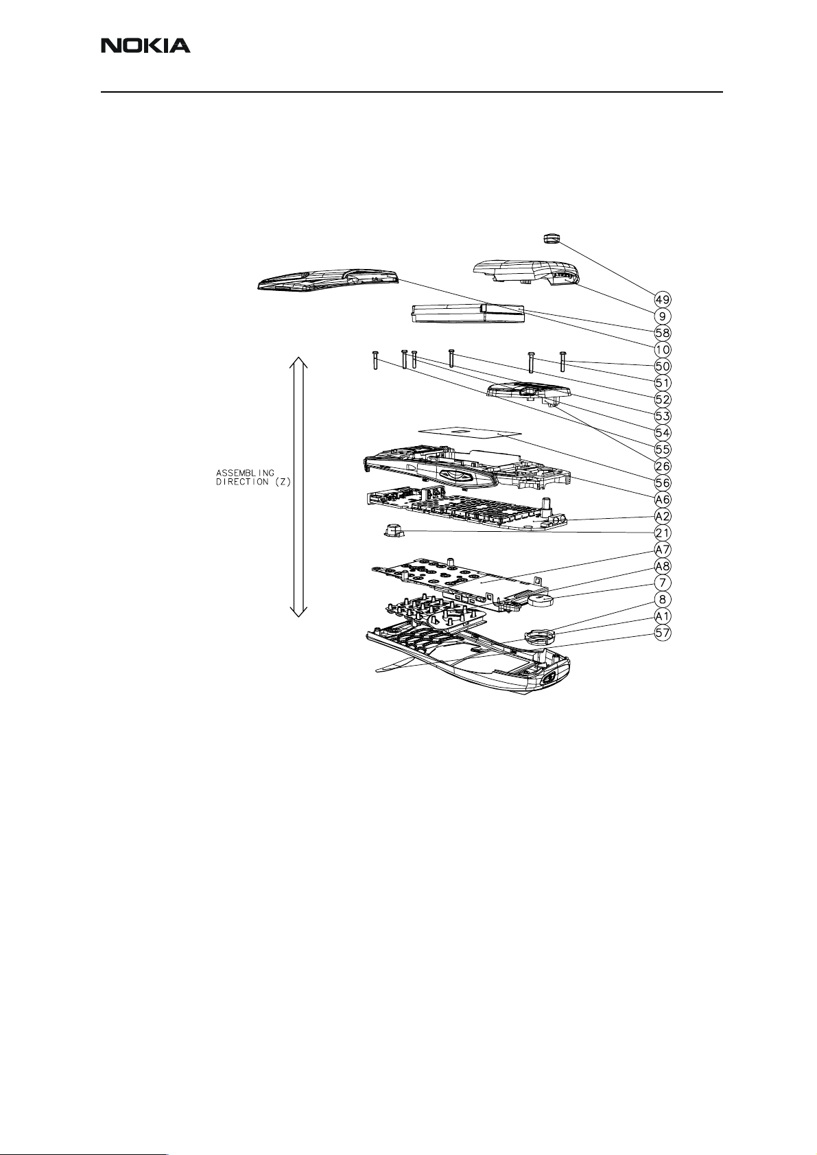
Exploded RH-13 Assembly
Figure 1: All parts and subassemblies of RH-13
Issue 1 11/02 ãNokia Corporation Page 3
Page 4
RH-13
Assembly & Disassembly Instructions CCS Technical Documentation
Step-by-Step Assembly Instructions
Wear cover gloves or finger covers and a wrist strap when assembling the phone.
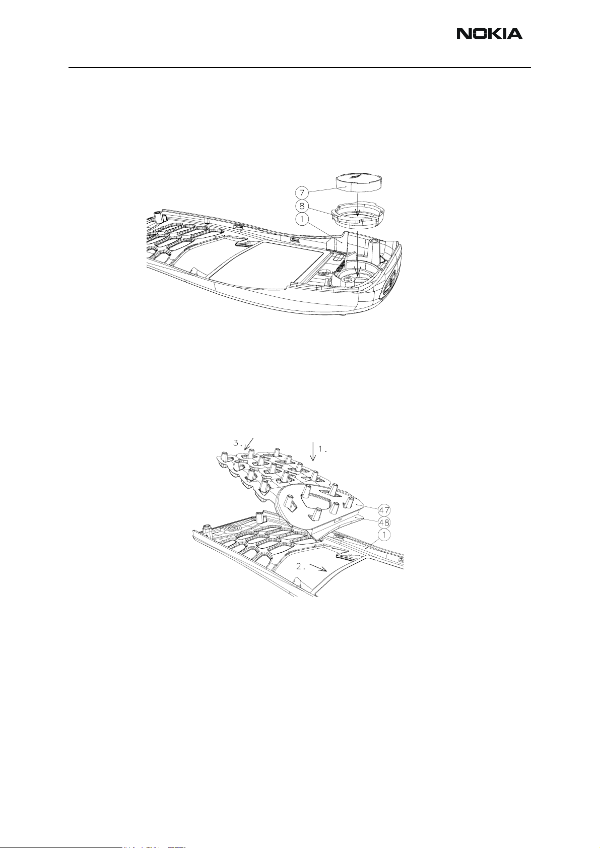
1. Insert Speaker (and gasket) to A-cover assembly
Insert a speaker and a gasket together before assembling to A-cover. Be careful with the
speaker's springs.
Note: Alignment: Speaker gasket's "wings" towards A-cover's screwing towers.
2. Insert Keymat to A-cover
Follow steps 1-3 as shown in the figure. Pass the softkey (48) under the A-cover (1) flip.
It is tight but it will pass. Focus key embosses to holes located in A-cover.
Page 4 ãNokia Corporation Issue 1 11/02
Page 5
RH-13
CCS Technical Documentation Assembly & Disassembly Instructions
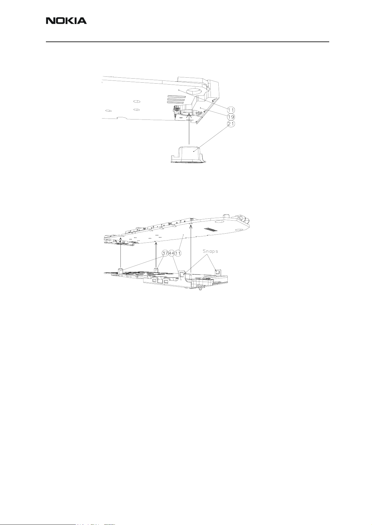
3. Insert microphone to system connector
Look at the figure above carefully.
4. Insert LCD-module to PWB
Remove the display cover tape first. The display “face” needs to be blown with ionized air
before assembling. Focus pin at upper end of lightguide (37) to hole in PWB (11) and
screw towers of lightguide to cutouts on edge of PWB.
LCD module is properly assembled when snaps joints in metal frame (44) clicks to PWB.
Blow module and A-cover with ionized air.
Note: Ensure that there is no debris on the window.
Issue 1 11/02 ãNokia Corporation Page 5
Page 6
RH-13
Assembly & Disassembly Instructions CCS Technical Documentation
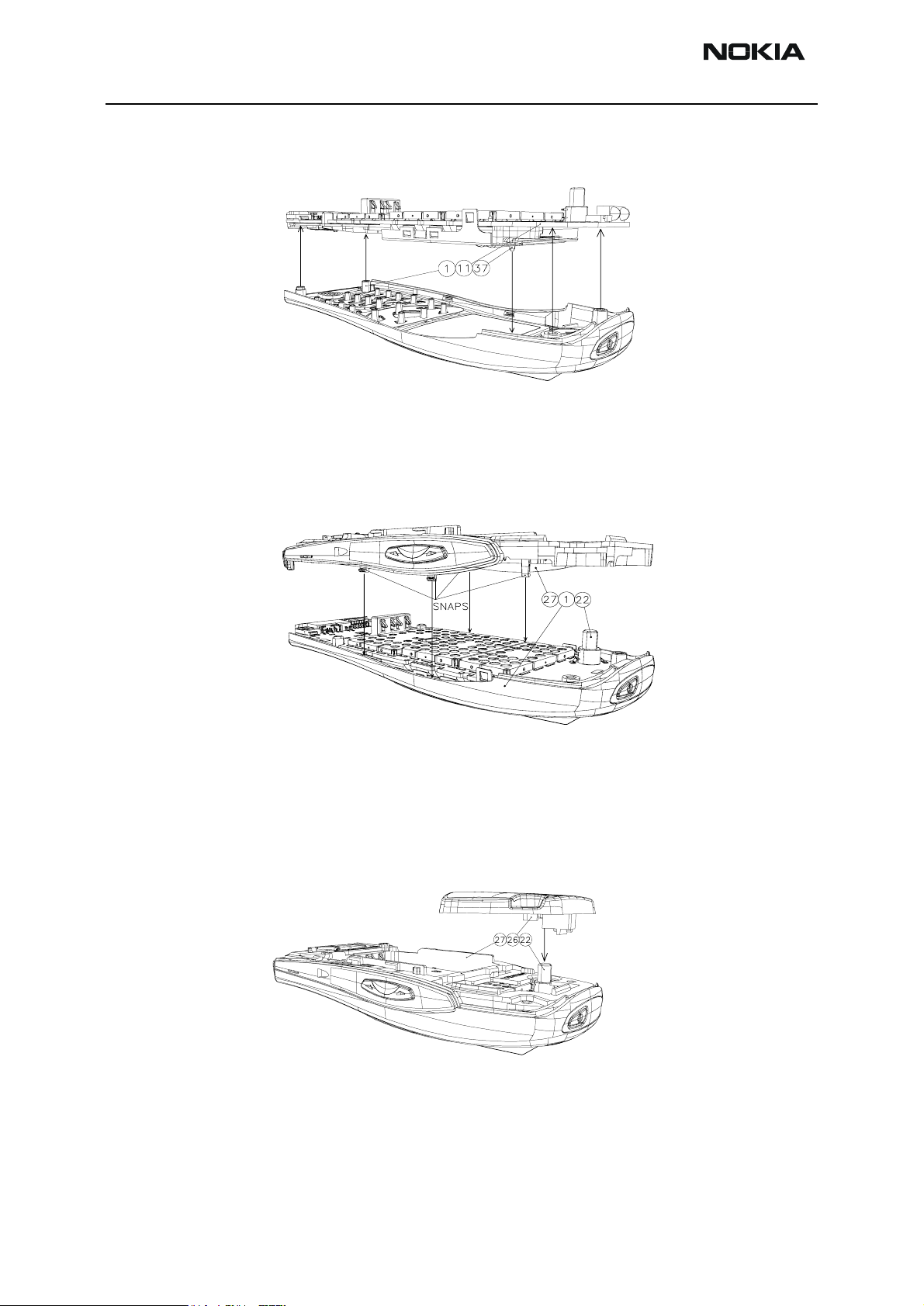
5. Insert LCD / PWB assembly to A-cover
Before assembling LCD / PWB assembly to A-cover, check the placement of speaker
assembly in A-cover. Screw towers in A-cover guides LCD / PWB assembly.
6. Insert D-cover assembly
D-cover (27) is correctly inserted when you feel four snap joints clicking onto the Acover (1). Push the D-cover assembly downwards quite hard. Be careful not to damage
the springs of the battery connector by metal deck.
7. Insert antenna
Wear gloves or rubber fingertips when handling the antenna (26). The antenna needs to
undergo a visual inspection (flash, discoloration, etc) before assembling. Assembling
guidance is in antenna connection to PWB (Rf-connector (22)).
Page 6 ãNokia Corporation Issue 1 11/02
Page 7

RH-13
CCS Technical Documentation Assembly & Disassembly Instructions
8. Insert screws
The estimated torque according to the screw trial for the all six screws is 22 Ncm and
speed of rotation 480 rpm by using Torx+, 1.8x9 Deprag, automatic feeding 708U driver.
Screwing order for pre-production is 50, 51, 52, 53, 54, and 55. Screwing order possibilities for testing purposes is limited to six (3!=3x2x1=6).
9. Insert antenna-cover to RH-13 assembly
In step one, push the front end of the antenna cover downwards until it snaps from four
snap joints in it. Be careful not to break them. Step two shows how to click the two
lower and bigger snap joints last.
Issue 1 11/02 ãNokia Corporation Page 7
Page 8

RH-13
Assembly & Disassembly Instructions CCS Technical Documentation
10. Insert dust cap for rf-connector
Push the dust cap downwards until it reaches the top surface of the antenna cover.
Additional assembly instructions
1. Insert type label to metal deck
Focus type label (56) hole to hole located in metal deck (28).
Page 8 ãNokia Corporation Issue 1 11/02
Page 9

RH-13
CCS Technical Documentation Assembly & Disassembly Instructions
2. Insert battery to RH-13 assembly
In step one, push the battery (58) against the springs of the battery connector (25).
In step two, push the battery from its front end downwards until it snaps onto the metal
deck (28).
3. Insert battery-cover to RH-13 assembly
In step one, push the battery cover (10) downwards in the Z-direction until it hits the Dcover (27). In step two, push the battery cover towards the antenna cover (9) until it
snaps from the front-end snap joint in it. Make sure all five (two on each side and one at
the bottom end) bonding hooks of the battery cover are properly hooked.
Issue 1 11/02 ãNokia Corporation Page 9
Page 10

RH-13
Assembly & Disassembly Instructions CCS Technical Documentation
4. Insert IR-window to A-cover assembly
The IR-window is properly inserted when all four snaps are locked.
Exploded D-cover assembly
Insert volume key (32) before volume switch (31). Push metal deck (28) downwards from
its sides near hooks until it snaps into D-cover (27). Push vibrator (29), SIM reader (33)
and buzzer (30) into their places in D-cover. Check the correct position of SIM-Reader.
Heat stake SIM latch and metal deck using soldering iron, for example.
Page 10 ãNokia Corporation Issue 1 11/02
Page 11

RH-13
CCS Technical Documentation Assembly & Disassembly Instructions
Disassembling the RH-13 Transceiver
Preparation for Disassembly
Disassembly Tools
Shown left to right: Torque-limiting screwdriver (torque set at 22N-cm), fiberglass soldering aid, and T6 Torx+ driver.
ESD Protection
ESD protection should be used when handling the PWB and other electronic components. The photo above shows a wrist strap, which can be grounded to a bench. This or
some other form of ESD protection should be used when handling the phone.
Issue 1 11/02 ãNokia Corporation Page 11
Page 12

RH-13
Assembly & Disassembly Instructions CCS Technical Documentation
Step-by-Step Disassembly Instructions
1. Remove battery-cover from Mozart assembly
Slide battery cover backwards in Y-direction while pushing hard from its middle front
area using your thumb. Slide the battery cover long enough to release snap joints and
hooks on sides of it.
2. Remove dust cap for rf-connector from antenna cover
Lift dust cap upwards from its hole using your fingernail or a screwdriver with a chisel
point.
3. Remove antenna-cover from Mozart assembly
Release two snap joints one after another, first at the rear end of the cover. Use a screwdriver as a lever arm between the D-cover and the Antenna-cover.
Page 12 ãNokia Corporation Issue 1 11/02
Page 13

RH-13
CCS Technical Documentation Assembly & Disassembly Instructions
4. Remove screws
The estimated optimal torque for the all six screws is 22 Ncm and the speed of rotation
480 rpm. The unscrewing order for pre-production is in the reverse order to screwing;
55, 54, 53, 52, 51, and 50. The screwing order possibilities for testing purposes is limited
to six (3!=3x2x1=6).
5. Remove antenna
Wear gloves or rubber fingertips when handling the antenna.
6. Remove D-cover assembly
The D-cover is correctly removed when the four side snap joints of the D-cover are
released from the A-cover. Use your fingernails or a screwdriver with a chisel point
between the A and D-covers at the middle of the snap joint area to do the operation.
Note: Screwdriver must not hit the engine module or components on it during disas-
sembly. Be also careful not to scratch covers.
On the next page you can see the removal operations of the subassemblies and parts of
Issue 1 11/02 ãNokia Corporation Page 13
Page 14

RH-13
Assembly & Disassembly Instructions CCS Technical Documentation
the D-cover assembly.
7. Remove parts from D-cover assembly
Lift vibrator, SIM reader and buzzer out of their slots of D-cover using screwdriver with
chisel point or your fingertips. Release both snap joints of volume key before disassembling volume switch.
Page 14 ãNokia Corporation Issue 1 11/02
Page 15

RH-13
CCS Technical Documentation Assembly & Disassembly Instructions
8. Remove LCD / PWB assembly from A-cover
Screw towers in A-cover guides LCD / PWB assembly.
Note: Gloves and ESD protection are mandatory in this phase of disassembly to pre-
vent fingerprints and damage in engine.
9. Remove LCD-module from PWB
LCD module is properly disassembled when two snaps joints in metal frame are released
from PWB.
Note: Gloves are mandatory if LCD-module will be reused. Also use ionized air for
clean dirt from LCD before assembling it back to A-cover. Handle the elastomer connector with care.
10. Remove Keymat from A-cover
Lift keymat upwards from its rear end first. Then slide softkey away from its recess.
Issue 1 11/02 ãNokia Corporation Page 15
Page 16

RH-13
Assembly & Disassembly Instructions CCS Technical Documentation
Additional disassembly instructions
1. Remove battery from Mozart assembly
Option 1: Lift battery upwards from its front end first by using screwdriver or your fingertip.
Option 2: Use your palm as a cup while hitting phone slightly towards the cup, battery
side down.
2. Remove speaker and speaker gasket from A-cover
Remove speaker and gasket by lifting from gasket using screwdriver or your fingertip.
Note: Do not touch the springs of speaker as they can be damaged.
Page 16 ãNokia Corporation Issue 1 11/02
Page 17

RH-13
CCS Technical Documentation Assembly & Disassembly Instructions
3. Remove IR-window from A-cover assembly
Start with snap joint at the middle of IR-lens by pushing it with screw driver with chisel
point. There are four snap joints altogether.
4. Remove LCD gasket from A-cover
Tear gasket off from A-cover starting from the corner shown in figure above.
5. Remove microphone from system connector
Lift microphone and gasket out from system connector.
Issue 1 11/02 ãNokia Corporation Page 17
Page 18

RH-13
Assembly & Disassembly Instructions CCS Technical Documentation
This page intentionally left blank.
Page 18 ãNokia Corporation Issue 1 11/02
 Loading...