

Page 1

Programmes After Market Services
NPE-4 Series Cellular Phones
5 - Service Tools
Original ãNokia Corporation Page 5-1
Page 2

NPE-4
5 - Service Tools PAMS Technical Documentation
Table of Contents
Page No.
Service Tools ........................................................................................................................... 5
Supported operating systems ..................................................................................... 5
Hardware requirement ................................................................................................. 5
List of service tools ........................................................................................................ 5
Setup instructions ......................................................................................................... 6
Flash concept ........................................................................................................... 6
Flash concept - POS (Point of sale) ................................................................... 7
JBV-1 Flash concept .............................................................................................. 8
Jig concept ............................................................................................................... 9
MJF-9 service concept .......................................................................................... 10
Parallel flash concept ............................................................................................ 11
Flash adapter FLA-22 .................................................................................................... 12
List of modules ........................................................................................................ 12
Technical specification ......................................................................................... 12
DC characteristics .................................................................................................. 12
Modes of operation ............................................................................................... 12
Mechanical characteristics .................................................................................. 13
Environmental conditions .................................................................................... 13
Temperature conditions ................................................................................ 13
JBT-9 Bluetooth test & interface box (sales pack) ........................................ 15
Product code .................................................................................................... 15
View of JBT-9 with antenna ........................................................................ 15
Hardware instructions .......................................................................................... 15
Hardware needed to use JBT-9 ................................................................... 15
Use of JBT-9 stand-alone ..................................................................................... 16
Attenuation settings ............................................................................................. 16
Setup for BER testing ............................................................................................ 16
SW instructions for BER-testing ........................................................................ 17
Use of JBT-9 as service interface ....................................................................... 18
Phoenix connection setup for JBT-9 as service interface ........................... 18
Attenuation setting via jumper .......................................................................... 19
LED indication of JBT-9 ........................................................................................ 19
Re-flash of JBT-9 .................................................................................................... 19
Abbreviations .......................................................................................................... 20
Page 5-2 ãNokia Corporation Original
Page 3

NPE-4
PAMS Technical Documentation 5 - Service Tools
Table of Contents
Page No.
MJS-40 repair jig ........................................................................................................... 21
Introduction ............................................................................................................. 21
List of mechanical parts ..................................................................................... 22
Packing material & marketing material ....................................................... 22
Exploded view ......................................................................................................... 23
MJF-9 docking station ................................................................................................. 24
Introduction ............................................................................................................. 24
List of modules ........................................................................................................ 24
Technical Data ......................................................................................................... 24
DC characteristics ........................................................................................... 24
D- connector signals ...................................................................................... 24
Mechanical characteristics .................................................................................. 25
Environmental conditions .................................................................................... 26
Temperature conditions ................................................................................ 26
Instructions of MBUSIBI connector changing ........................................ 26
List of Figures
1 Main dimensions of FLA-22 ................................................................................ 13
2 Exploded view of FLA-22 ...................................................................................... 14
3 Main dimensions of MJF-9 .................................................................................. 25
List of Tables
1 List of Modules ........................................................................................................ 12
2 Electrical ratings ..................................................................................................... 12
3 Mechanical characteristics .................................................................................. 13
4 Allowed ambient temperatures .......................................................................... 13
5 D-Connector signal description ......................................................................... 25
Original ãNokia Corporation Page 5-3
Page 4

NPE-4
5 - Service Tools PAMS Technical Documentation
This page intentionally left blank
Page 5-4 ãNokia Corporation Original
Page 5
NPE-4
PAMS Technical Documentation 5 - Service Tools
Service Tools
Supported Operating Systems
Windows 95, 98, 2000, ME and NT 4.0 (SP4).
Hardware requirements
Minimum:
Processor 233 MHz, RAM memory 64 MB, Disk space 50-100 MB.
Recommended for Windows 2000:
Processor 700 MHz, RAM memory 512 MB, Disk space 50-100 MB.
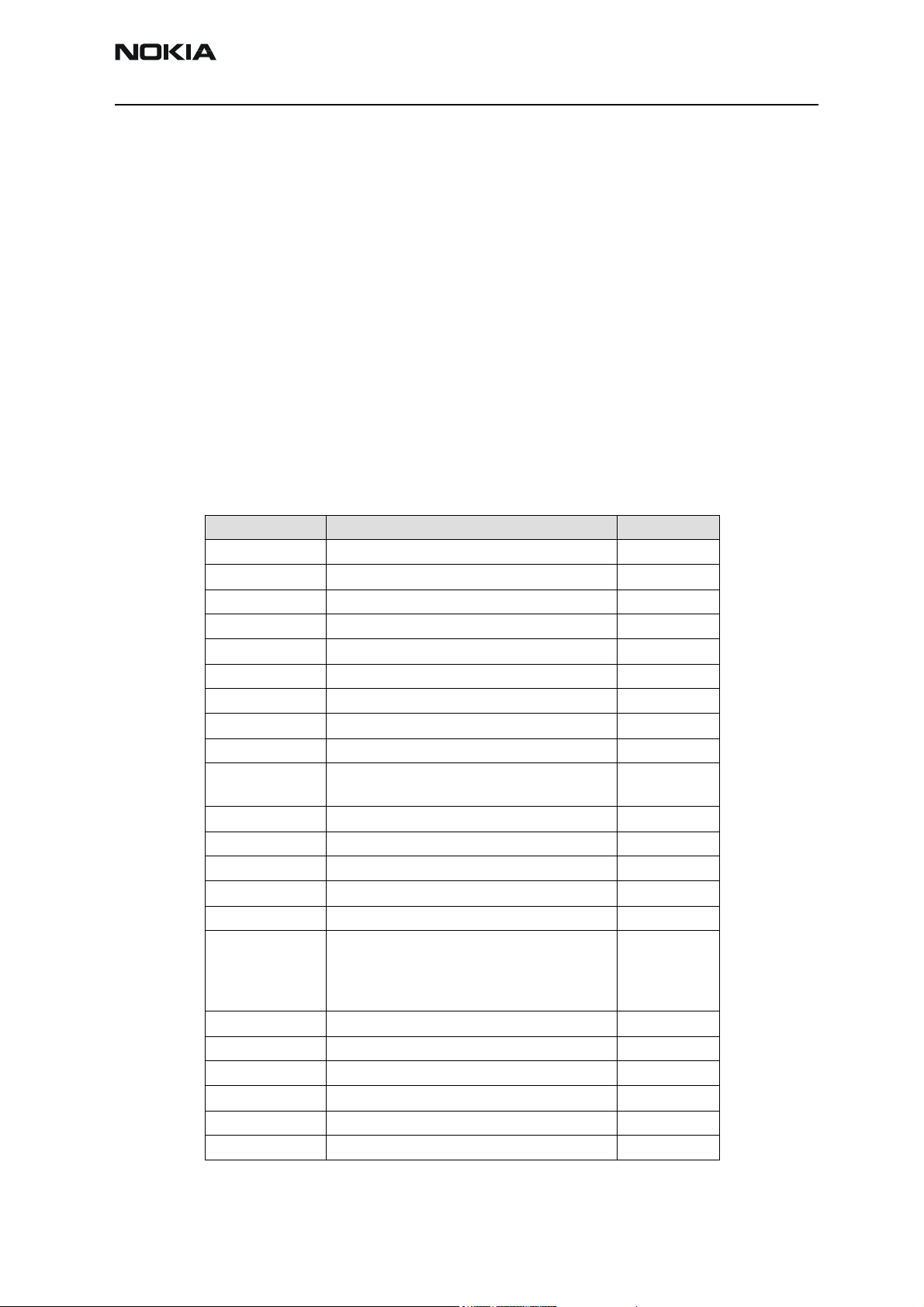
List of service tools
The table below gives a short overview of service tools that can be used for testing, error
analysis and repair of product NPE-4, refer to various set-ups.
Type designator Description Part code
FLA-22 Point of sale flash adapter 0775299
DAU-9S Service MBUS cable 0730108
FLC-2 Power cable 0730185
PCS-1 DC power cable 0730012
SCB-3 DC cable 0730114
XCS-1 Service cable 0730218
XCS-4 Modular cable 0730178
XRE-2 BT cable 0730237
XRC-1b RF antenna cable 0730128
FLS-4 POS flash dongle for E/A area
POS flash dongle for APAC area
FPS-8 Parallel flash prommer box 0080396
Printer cable (inc. in FSP-8 sales pack) 0730029
FPS-8C Flash prommer box 0080321
AXS-4 D9 cable (inc. in FPS-8 & FPS8C sales pack) 0730090
PKD-1 Software protection key 0750018
Phoenix Service SW
Phoenix Service SW in CD-ROM
NPE-4 Flash SW data
NPE-4 Flash SW data in CD-ROM
ACP-8 AC charger (inc. in FPS-8 sales pack) 0680032
JBT-9 BT Test box 0770336
JBV-1 Docking station 0770298
MJF-9 Docking station adapter 0775298
MJS-40 Module jig 0770385
HCA-1 Cable support part 0770433
0081483
0081481
8409031
0775311
8410149
0775320
Original ãNokia Corporation Page 5-5
Page 6
NPE-4
5 - Service Tools PAMS Technical Documentation
Setup Instructions
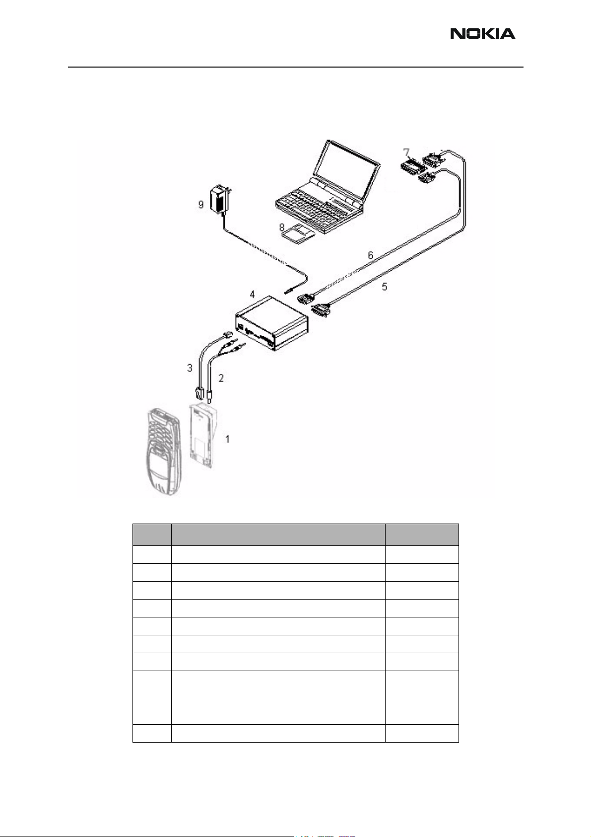
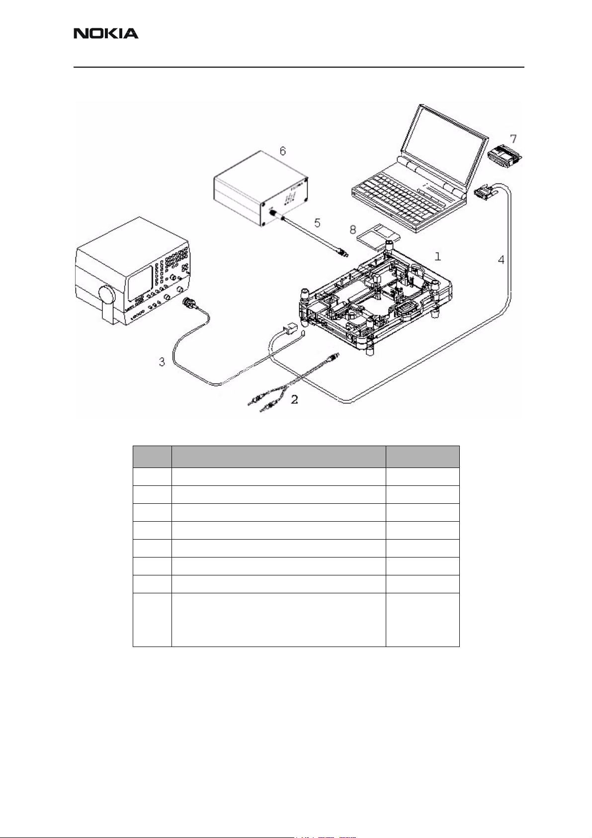
Flash Concept
Item: Service accessory: Product code:
1 FLA-22, Point of sales flash adapter 0775299
2 FLC-2, DC power cable 0730185
3 XCS-4, Modular cable 0730178
4 FPS-8, Flash prommer box 0080321
5 Printer cable, incl. in FPS-8 sales pack 0730029
6 AXS-4, D9 cable, incl. in FPS-8 sales pack 0730090
7 PKD-1, Software protection key 0750018
8 Phoenix Service SW
Phoenix Service SW in CD-ROM
NPE-4 Flash SW data
NPE-4 Flash SW data in CD-ROM
9 AC Charger, incl. in FPS-8 sales pack 0680032
8409031
0775311
8410149
0775320
Page 5-6 ãNokia Corporation Original
Page 7
NPE-4
PAMS Technical Documentation 5 - Service Tools
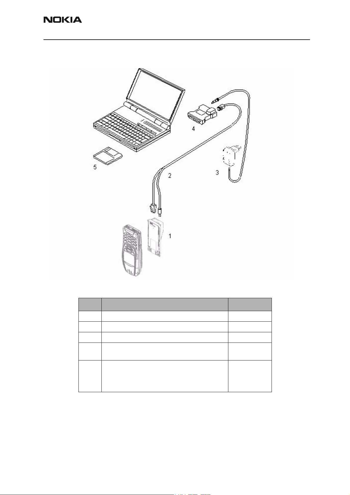
Flash Concept - POS (Point of Sale)
Item: Service accessory: Product code:
1 FLA-22, Point of sales flash loading adapter 0775299
2 XCS-1, service cable 0730218
3 ACP-8 AC Charger 0770298
4 FLS-4, POS flash dongle for E/A area
FLS-4, POS flash dongle for APAC area
5 Phoenix Service SW
Phoenix Service SW in CD-ROM
NPE-4 Flash SW data
NPE-4 Flash SW data in CD-ROM
0081483
0081481
8409031
0775311
8410149
0775320
Original ãNokia Corporation Page 5-7
Page 8
NPE-4
5 - Service Tools PAMS Technical Documentation
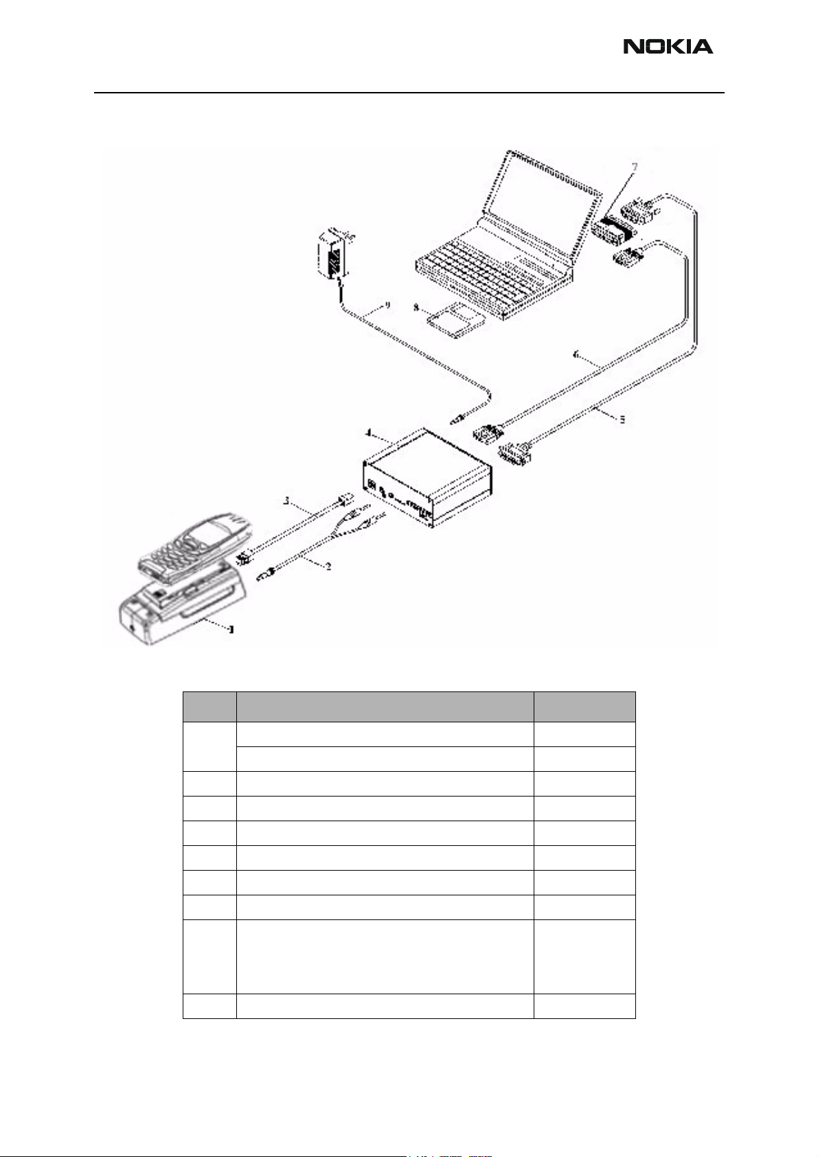
JBV-1 Flash Concept
Item: Service accessory: Product code:
1 JBV-1, Docking station 0770298
MJF-9, Docking station adapter 0775298
2 PCS-1, DC power cable 0730012
3 XCS-4, Modular cable 0730178
4 FPS-8, Flash prommer box 0080321
5 Printer cable, incl. in FPS-8C sales pack 0730029
6 AXS-4, D9 ? D9 cable, incl. in FPS-8C sales pack 0730090
7 PKD-1, Software protection key 0750018
8 Phoenix Service SW
Phoenix Service SW in CD-ROM
NPE-4 Flash SW data
NPE-4 Flash SW data in CD-ROM
9 AC Charger, incl. in FPS-8 sales pack 0680032
8409031
0775311
8410149
0775320
Page 5-8 ãNokia Corporation Original
Page 9
NPE-4
PAMS Technical Documentation 5 - Service Tools
Jig Concept
Item: Service accessory: Product code:
1 MJS-40, Module jig 0770385
2 PCS-1, DC power cable 0730012
3 XRC-1b, RF antenna cable 0730128
4 DAU-9S, Service MBUS cable 0730108
5 XRE-2, BT cable (optional also antenna available) 0730237
6 JBT-9, BT-Test-Box (optional for BT test) 0770336
7 PKD-1, Software protection key 0750018
8 Phoenix Service SW
Phoenix Service SW in CD-ROM
NPE-4 Flash SW data
NPE-4 Flash SW data in CD-ROM
8409031
0775311
8410149
0775320
Original ãNokia Corporation Page 5-9
Page 10

NPE-4
5 - Service Tools PAMS Technical Documentation
MJF-9 Service Concept
Item: Service accessory:
1 JBV-1, Docking station 0770298
2 MJF-9, Docking station adapter 0775298
3 HCA-1,Cable support part 0770433
4 SCB-3, DC?DC cable 0730114
5 XRC-1b, RF antenna cable 0730128
6 PCS-1, DC power cable 0730012
7 DAU-9S, Service MBUS cable 0730108
8 PKD-1, Software protection key 0750018
9 Phoenix Service SW
Phoenix Service SW in CD-ROM
NPE-4 Flash SW data
NPE-4 Flash SW data in CD-ROM
Product
code:
8409031
0775311
8410149
0775320
Page 5-10 ãNokia Corporation Original
Page 11

NPE-4
PAMS Technical Documentation 5 - Service Tools
Parallel Flash Concept
Item: Service accessory: Product code:
1 MJF-9, Docking station adapter 0775298
2 JBV-1, Docking station 0770298
3 XCS-4, Modular cable 0730178
4 PCS-1, DC power cable 0730012
7 AXS-4, D9 ? D9 cable, incl. in FPS-8C sales pack 0730090
8 Printer cable, incl. in FPS-8C sales pack 0730029
10 PKD-1, Software protection key 0750018
11 Phoenix Service SW
Phoenix Service SW in CD-ROM
NPE-4 Flash SW data
NPE-4 Flash SW data in CD-ROM
17 FPS-8C, Parallel flash prommer 0080396
8409031
0775311
8410149
0775320
Original ãNokia Corporation Page 5-11
Page 12

NPE-4
5 - Service Tools PAMS Technical Documentation
Flash adapter FLA-22
Flash adapter FLA-22 is designed for regional Service Centers and POS (Point of Sales) to replace
phones own battery when flashing the phone. Furthermore it can be used as a dummy battery. Features:
Normal mode operation
Powered by charger or external power supply
Over current protection
Over voltage protection
Voltage polarity protection
BSI connected to prommer
List of Modules
Table 1: List of Modules
Name of modules NMP type NMP code Notes
Flash adapter FLA-22 0775299 Flash adapter for AMS usage
Technical Specifications
DC Characteristics
Table 2: Electrical ratings
Parameter Min Nom Max Note
Input voltage (charger) 5.5V - 16V
Supply voltage (power supply) 3.0V - 4.2V
Vbatt (charger) 3.9V 4.0V 4.1V Regulated
Vbatt (power supply) 3.0V - 4.2V No regulation
Vbatt current (charger) 210mA - 300mA Limited
Vbat protection current 2A Resettable fuse
BTEMP Normal mode 47k Resistor
BSI Normal mode 39k Resistor
Modes of operation
Flash adapter FLA-22 can be used in two operation modes:
Normal mode (startup in normal mode, power key press needed to flash)
Page 5-12 ãNokia Corporation Original
Page 13
NPE-4
PAMS Technical Documentation 5 - Service Tools
Local mode (can be forced to local mode in Phoenix)
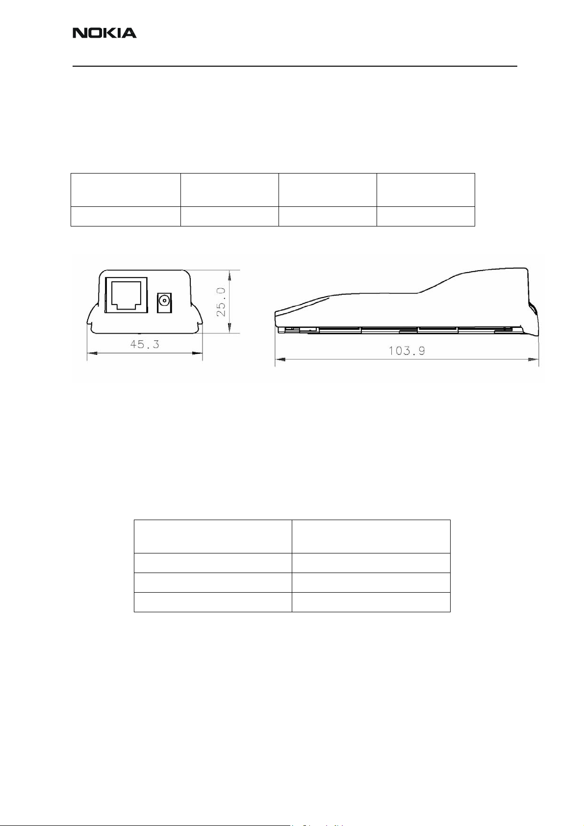
Mechanical Characteristics
Table 3: Mechanical Characteristics
Unit Dimensions (mm)
(W x H x D)
FLA-22 45,3x25.0x103,9 200 PC/ABS
Figure 1. Main dimensions of FLA-22.
Environmental Conditions
Temperature Conditions
Weight
(g)
Material
Table 4: Allowed Ambient Temperatures
Ambient temperature
(degrees Celsius)
Operating temperature +5…+35
Storage temperature -30…+60
Humidity RH Max. 90%
Original ãNokia Corporation Page 5-13
Page 14

NPE-4
5 - Service Tools PAMS Technical Documentation
Figure 2. Exploded view of FLA-22
Page 5-14 ãNokia Corporation Original
Page 15

NPE-4
PAMS Technical Documentation 5 - Service Tools
JBT-9 Bluetooth Test & Interface box (Sales Pack)
The JBT-9 testbox is a generic device to perform Bluetooth Bit Error Rate testing and
doing cordless FBUS connection via Bluetooth. An ACP-8x charger is needed for BER
testing and AXS-4 cable in case of cordless testing interface usage.
Sales package includes:
• JBT-9 testbox 0770336
• SMA stub antenna 066P056
• Installation and warranty information9360613
Product Code
JBT-9 sales kit code: 0081490
View of JBT-9 with antenna
Hardware needed to use JBT-9
• JBT-9 Bluetooth testbox
• SMA stub antenna (part of sales kit)
• ACP-8x charger (x denotes region, e.g. ACP-8E for Europe)
• AXS-4 serial cable (0730090)
Original ãNokia Corporation Page 5-15
Page 16

NPE-4
5 - Service Tools PAMS Technical Documentation
Use of JBT-9 Stand-alone
The JBT-9 Box can be used without any PC connection as loop-back device for BT testing. To verify the products BT functionality, a Bit Error Rate test needs to be performed
against JBT-9. The test is controlled and executed by Phoenix service software.
Attenuation settings:
The JBT-9 attenuation is used to reduce the BT RF range. The default factory setting of
internal attenuation is –36dBm (refer to related chapter below). This reduces the typical RF range to less than 0.5 m. In case that distance is too short to perform tests over
the air, the internal attenuation can be changed as described in the JBT-9 sales package
user guide. In case that a service jig is directly connected to the box SMA RF I/O connector, it is recommended to work with the maximum internal attenuation (default factory
setting).
PLEASE NOTE:
When the JBT-9 is connected to the PC via AXS-4 serial cable and used as BT service
interface, the BT Phoenix driver is controlling the internal attenuation of JBT-9. Details
are described in chapter 4.
Setup for BER testing
• Connect SMA stub antenna or service jigs’ BT RF cable to JBT-9’s RF/IO connector.Connect ACP-8x charger to JBT-9 power connector.
• Make sure that distance between phone and JBT-9 does not exceed 5 cm distance when using default attenuation setting.
• BER test result is OK when BER is less than 0.1%
Page 5-16 ãNokia Corporation Original
Page 17

NPE-4
PAMS Technical Documentation 5 - Service Tools
• Note that the phone connection to the PC is specific to the tested phone. For
details refer to the related chapter in the service manual.
SW instructions for BER testing
• Make sure that the phone’s product support modules are properly loaded by
Phoenix SW.
• Choose “Testing” from the “Maintenance” menu and choose “Bluetooth Locals”.
• Enter JBT-9’s Ser.No. (12 digits from the type label) in the field “Counterpart
Device Address”.
• Make sure that whole freq. range is chosen to test all BT channels or use local
frequency range
• Choose “300” Bitframes.
• Press the “Run” button to perform the BER test.
Original ãNokia Corporation Page 5-17
Page 18

NPE-4
5 - Service Tools PAMS Technical Documentation
Use of JBT-9 as service interface
The JBT-9 can be connected to a PC by using an AXS-4 serial cable. The Bluetooth wireless technology can be used to establish a FBUS connection without any cables and line
of sight. The phone must be switched on with SIM card and all Phoenix functions are
working as long as the phone is in normal mode.
PHOENIX connection setup for JBT-9 as service interface
To use JBT-9 as service interface, the “BTFB” driver must be chosen when making the
connection configuration.
PROCEDURE:
When choosing a BTFB driver connection, the JBT-9 is starting an inquiry. The inquiry is
stopped when one other BT product is found. Therefore the BT_BOX_RANGE_INQUIRY
Page 5-18 ãNokia Corporation Original
Page 19

NPE-4
PAMS Technical Documentation 5 - Service Tools
should be MIN to ensure that only one product is in range of JBT-9. The JBT-9 is requesting a connection on the product. To establish the connection, the connection request
must be confirmed and the BT_BOX_PIN must be entered on the phone. When the connection is established, Phoenix SW is switching the JBT-9 range to
BT_BOX_RANGE_CONNECT.
Attenuation setting via Jumper
Internal possible settings after JBT-9 boot-up. The precision of the internal attenuation is
specified to be +/- 5dBm. During test the attenuation can also be changed via Phoenix
SW.
Default
attenuation
21 dB Closed (GND) Open 1,5 m
21 dB Open Closed (GND) 1,5 m
7 dB [MIN] Open Open 8 m
36 dB [MAX] Closed (GND) Closed (GND) 0,5 m X
GPP10 GPP11 Max. RF range Factory
LED Indication of JBT-9
ACTION STATUS-LED BER TEST-LED FBUS-LED POWER-LED
POWER ON
FBUS ON
INQUIRY BLINKING
CONNECTED ON
setting
BER-TEST
LOOP-BACK ON
ERROR ON RED
BOX READY ON GREEN
1. ON
Re-flash of JBT-9
The JBT-9 Box SW can be updated using the Bluetooth Flasher from the “Flashing” menu
in Phoenix SW. If the Bluetooth Flasher is not visible in the flashing menu, make sure
that a BT product is chosen from the “File” menu.
• Select the COM port where JBT-9 is connected.
Original ãNokia Corporation Page 5-19
Page 20

NPE-4
5 - Service Tools PAMS Technical Documentation
• Make use that in the actual selected connection is “NO CONNECTION” in Phoenix
SW to avoid any COM port sharing problems.
• Select the “bin” file and start the flashing procedure
The latest “bin” file can be loaded from the Software area at PAMS internet webpage.
Abbreviations
BER = Bit Error Rate
BT = Bluetooth
COM = (serial communication port)
FBUS = (NOKIA proprietary communication bus)
IO = Input / Output
PAMS = Program After Market Services
PC = Personal Computer
RF = Radio Frequency
SMA = (sub miniature RF connector type)
SW = Software
Page 5-20 ãNokia Corporation Original
Page 21

NPE-4
PAMS Technical Documentation 5 - Service Tools
MJS-40 repair jig
Introduction
MJS-40 is a production, Aftersales and R & D engine module repair jig for NPE-4.
The purpose of the repair jig is to provide a method of applying voltage from an external
power supply when the module is out of its mechanics.
The repair jig provides following functions:
• Fused protection
• Overvoltage protection
• Reverse polarity protection
• ESD protection
• Decoupling capacitors
• Access to exposed components
• BlueTooth coupler
It is intended that the repair jig should be used under all circumstances where an external supply to the phone is required to be applied while the phone is out of its mechanics.
It should be noted that the supply voltage to the repair jig is intended to be the same as
normal battery voltage range i.e. 3.0-4.2V.
Nominal supply voltage is 3.6V.
Note: Supply voltage must not exceed 5V! (Fuse will blow)
Sales package products Product code
MJS-40 Module Jig 0770385
The MJS-40 is designed for testing/repairing the engine separately, engine mounted with
lightguide assembly or / and with keymat.
Note: Supplier has the warranty of the service tool. If repair of the service tool is necces-
sary, this is agreed between the supplier and the user of the service tool.
Original ãNokia Corporation Page 5-21
Page 22

NPE-4
5 - Service Tools PAMS Technical Documentation
List of mechanical parts
Part
number
1 Bottom SME5S758 1
2 Cover SME5S756 1
3 Latch part DMD04393 1
4 BN684 3x12
5 Guide pin plastic DMD2558POM 5
5 Ball SKF/RB-3.0/IV 640B006 1
6 Spring TFR0.35x3x5.5 640B000 1
8 Leck 9560062 8
9 Bottom foot 9460224 8
10 Hinge 6490013 3
11 Screw 965ZNM2.5x8 12
11 Screw 965ZN M2x4 4
12 Screw M2.5x6 6150411 7
Name of
Part
SN12771B
Material
code
640B003 2
Drawing
number
Qty Notes
13 LOI2_01 module 1
14 Btant2_01 module 1 Including 5420025 SMA
connector angle
15 Clamp 9510389 1
16 Screw M3x10 6160191 2
18 Ground pin SME9S216 4
Packing Material & Marking Material
Name Material code Pcs.
Carton 9650356 1
Foaming 9660112 5
Extra fuses 511A004 2
Type label 9380154 1
Warning label 9380160 1
Page 5-22 ãNokia Corporation Original
Page 23

NPE-4
PAMS Technical Documentation 5 - Service Tools
Exploded View
Original ãNokia Corporation Page 5-23
Page 24

NPE-4
5 - Service Tools PAMS Technical Documentation
MJF-9 Docking station
Introduction
Docking station adapter MJF-9 is designed for adapter between the Docking Station
JBV-1 and the tranceiver. Docking station adapter MJF-9 has following main electronic
function:
• Phone recognizing from BTEMP
With JBV-1 it is possible to calibrate and flash the transceiver.
List of modules
Name of module NMP code NMP code Notes
Docking station adapter MJF-9 0775298 Docking station adapter to AMS usage
Technical Data
DC characteristics
Parameter Min Nom Max
Recognizing voltage from BTEMP 0,108V 0, 111 0,114V
D- connector signals
D-connector (male) is between MJF-9 and JBV-1.
VBATT 1
14 VBAT_SENSE
VBATT 2
15 DC+
DC+ 3
16 +COUP
NC 4
17 NC
NC 5
18 NC
NC 6
19 NC
NC 7
20 NC
PHONE_RECOGNIZING 8
21 BTEMP
BSI 9
22 FBUS/TX
FBUS/RX 10
23 MBUS
GND(BUS) 11
24 VPP
GND 12
25 GND_SENSE
GND 13
Page 5-24 ãNokia Corporation Original
Page 25

NPE-4
PAMS Technical Documentation 5 - Service Tools
Table 5: D-connector signal description
Pin Signal Description Min Max
1,2 VBATT Battery voltage to phone 3.0V /0A 4.2V / 1.5A
3, 15 DC+ Supply voltage to JBV-1
4 NC Not connected
5 NC Not connected
6 NC Not connected
7 NC Not connected
8 PHONE_RECOGNIZING Phone recognizing from jig. Active low 0 +coup ( 3.3V)
9 BSI BSI signal from phone
10 FBUS/TX FBUS TX signal from modular connector
11 GND(BUS) GND from modular connector. Not con-
nected to battery GND on JBV-1
12,13 GND Battery voltage GND
14 VBATT_SENSE Battery voltage sense. Used for regulator
voltage feedback
16 +COUP Coupler voltage 3.0V 3.3V
17 NC Not connected
18 NC Not connected
19 NC Not connected
20 NC Not connected
21 BTEMP BTEMP signal from phone
22 FBUS/RX FBUS RX signal from modular connector
23 MBUS MBUS signal from modular connector
Mechanical characteristics
Unit Dimensions (mm) (W x H x D) Weight (g) Material
MJF-9 71,5 x 30,8 x 119,6 155 ABS/PC
Figure 3. Main dimensions of MJF-9
Original ãNokia Corporation Page 5-25
Page 26

NPE-4
5 - Service Tools PAMS Technical Documentation
Environmental Conditions
Temperature Conditions
Allowed ambient temperatures
Ambient temperature
(degrees Celsius)
Operating temperature +5…+35
Storage temperature -30…+60
Humidity RH Max. 90%
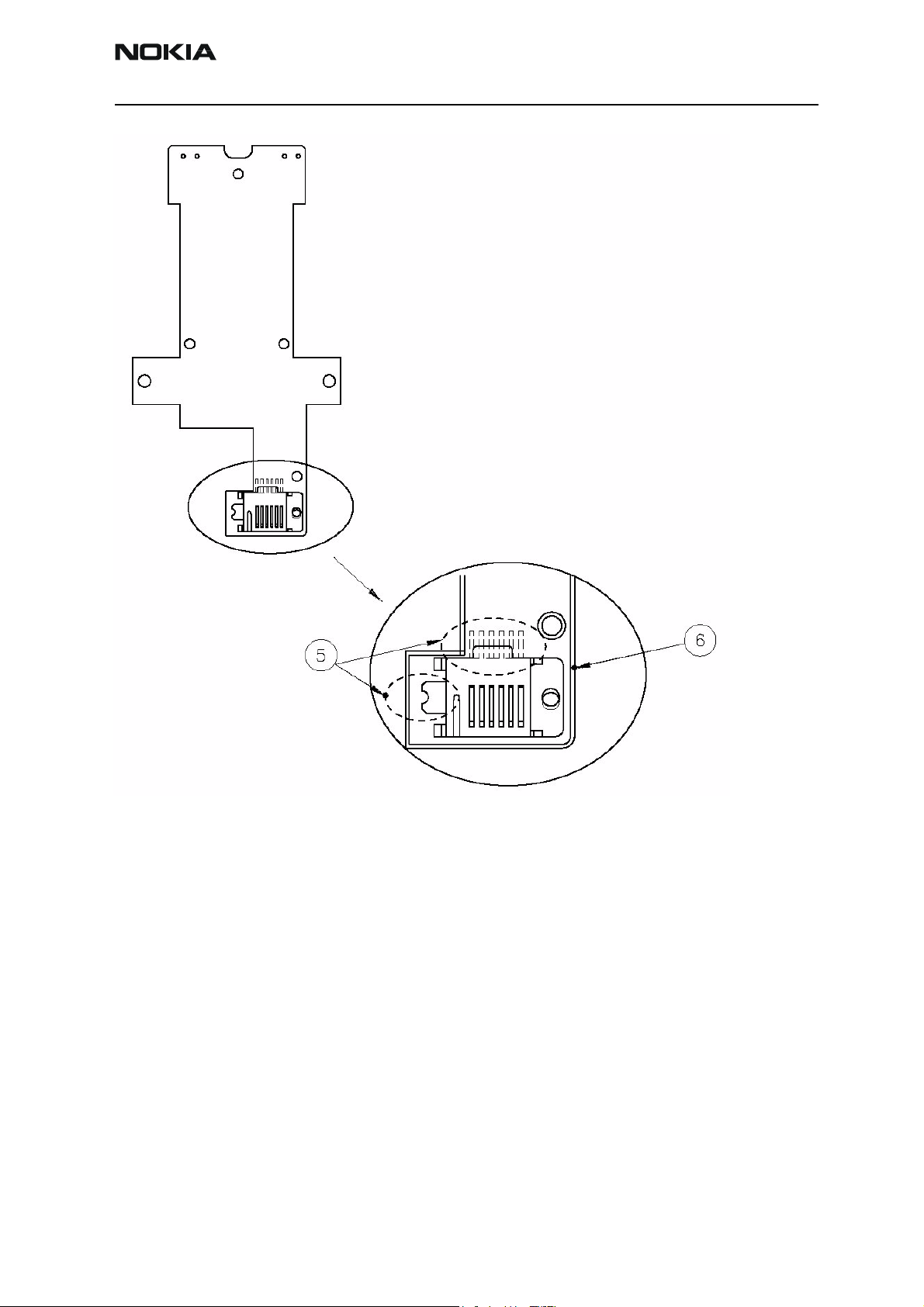
Instruction of MBUSIBI connector changing
1. Open the MJF-9 cover (1.) by screwing off 5 screws (2.)
2. Remove the PCB (3.) by screwing off these 4 screws (4.)
Page 5-26 ãNokia Corporation Original
Page 27
NPE-4
PAMS Technical Documentation 5 - Service Tools
2 Remove solder from MBUSIBI connector’s 6 pins and GND pin (5.)
3 Remove the connector and install new one on PCB
4 Ensure that the new MBUSIBI connector’s hole is against PCB’s hole (6.) and the
pins are in middle of pads
5 Solder the connector to its place
Original ãNokia Corporation Page 5-27
Page 28

NPE-4
5 - Service Tools PAMS Technical Documentation
This page intentionally left blank
Page 5-28 ãNokia Corporation Original
 Loading...