

Page 1

Nokia Customer Care
Service Manual
RM-443 (Nokia 6303 classic; L3&4)
Mobile Terminal
Part No: (Issue 2)
COMPANY CONFIDENTIAL
Copyright © 2009 Nokia. All rights reserved.
Page 2
Amendment Record Sheet
Amendment Record Sheet
Amendment No Date Inserted By Comments
Issue 1 03/2009 ET
Issue 2 03/2009 ET New attenuation values have been
added to the
section in the
Service Concepts
The
Checking antenna functionality
section has been updated in the
Troubleshooting
4-16 to 4-18).
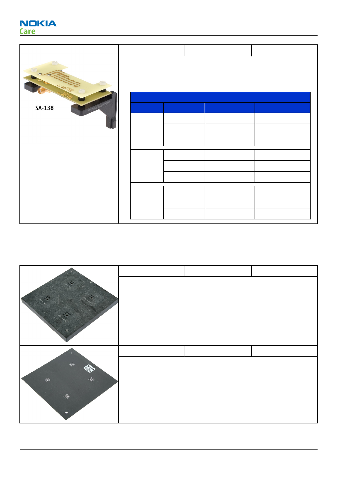
SA-138 RF coupler
Service Devices and
chapter (page 2-6).
chapter (pages
RM-443
RF
Page ii COMPANY CONFIDENTIAL Issue 2
Copyright © 2009 Nokia. All rights reserved.
Page 3

RM-443
Copyright
Copyright
Copyright © 2008 Nokia. All rights reserved.
Reproduction, transfer, distribution or storage of part or all of the contents in this document in any form
without the prior written permission of Nokia is prohibited.
Nokia, Nokia Connecting People, and Nokia X and Y are trademarks or registered trademarks of Nokia
Corporation. Other product and company names mentioned herein may be trademarks or tradenames of
their respective owners.
Nokia operates a policy of continuous development. Nokia reserves the right to make changes and
improvements to any of the products described in this document without prior notice.
Under no circumstances shall Nokia be responsible for any loss of data or income or any special, incidental,
consequential or indirect damages howsoever caused.
The contents of this document are provided "as is". Except as required by applicable law, no warranties of
any kind, either express or implied, including, but not limited to, the implied warranties of merchantability
and fitness for a particular purpose, are made in relation to the accuracy, reliability or contents of this
document. Nokia reserves the right to revise this document or withdraw it at any time without prior notice.
The availability of particular products may vary by region.
IMPORTANT
This document is intended for use by qualified service personnel only.
Issue 2 COMPANY CONFIDENTIAL Page iii
Copyright © 2009 Nokia. All rights reserved.
Page 4

RM-443
Warnings and cautions
Warnings and cautions
Warnings
•
IF THE DEVICE CAN BE INSTALLED IN A VEHICLE, CARE MUST BE TAKEN ON INSTALLATION IN VEHICLES FITTED
WITH ELECTRONIC ENGINE MANAGEMENT SYSTEMS AND ANTI-SKID BRAKING SYSTEMS. UNDER CERTAIN FAULT
CONDITIONS, EMITTED RF ENERGY CAN AFFECT THEIR OPERATION. IF NECESSARY, CONSULT THE VEHICLE DEALER/
MANUFACTURER TO DETERMINE THE IMMUNITY OF VEHICLE ELECTRONIC SYSTEMS TO RF ENERGY.
•
THE PRODUCT MUST NOT BE OPERATED IN AREAS LIKELY TO CONTAIN POTENTIALLY EXPLOSIVE ATMOSPHERES,
FOR EXAMPLE, PETROL STATIONS (SERVICE STATIONS), BLASTING AREAS ETC.
•
OPERATION OF ANY RADIO TRANSMITTING EQUIPMENT, INCLUDING CELLULAR TELEPHONES, MAY INTERFERE
WITH THE FUNCTIONALITY OF INADEQUATELY PROTECTED MEDICAL DEVICES. CONSULT A PHYSICIAN OR THE
MANUFACTURER OF THE MEDICAL DEVICE IF YOU HAVE ANY QUESTIONS. OTHER ELECTRONIC EQUIPMENT MAY
ALSO BE SUBJECT TO INTERFERENCE.
•
BEFORE MAKING ANY TEST CONNECTIONS, MAKE SURE YOU HAVE SWITCHED OFF ALL EQUIPMENT.
Cautions
•
Servicing and alignment must be undertaken by qualified personnel only.
•
Ensure all work is carried out at an anti-static workstation and that an anti-static wrist strap is worn.
•
Ensure solder, wire, or foreign matter does not enter the telephone as damage may result.
•
Use only approved components as specified in the parts list.
•
Ensure all components, modules, screws and insulators are correctly re-fitted after servicing and
alignment.
•
Ensure all cables and wires are repositioned correctly.
•
During testing never activate the GSM transmitter without a proper antenna load, otherwise the GSM PA
may be damaged.
Page iv COMPANY CONFIDENTIAL Issue 2
Copyright © 2009 Nokia. All rights reserved.
Page 5

RM-443
For your safety
For your safety
QUALIFIED SERVICE
Only qualified personnel may install or repair phone equipment.
ACCESSORIES AND BATTERIES
Use only approved accessories and batteries. Do not connect incompatible products.
CONNECTING TO OTHER DEVICES
When connecting to any other device, read its user’s guide for detailed safety instructions. Do not connect
incompatible products.
Issue 2 COMPANY CONFIDENTIAL Page v
Copyright © 2009 Nokia. All rights reserved.
Page 6

RM-443
Care and maintenance
Care and maintenance
This product is of superior design and craftsmanship and should be treated with care. The suggestions below
will help you to fulfil any warranty obligations and to enjoy this product for many years.
•
Keep the phone and all its parts and accessories out of the reach of small children.
•
Keep the phone dry. Precipitation, humidity and all types of liquids or moisture can contain minerals that
will corrode electronic circuits.
•
Do not use or store the phone in dusty, dirty areas. Its moving parts can be damaged.
•
Do not store the phone in hot areas. High temperatures can shorten the life of electronic devices, damage
batteries, and warp or melt certain plastics.
•
Do not store the phone in cold areas. When it warms up (to its normal temperature), moisture can form
inside, which may damage electronic circuit boards.
•
Do not drop, knock or shake the phone. Rough handling can break internal circuit boards.
•
Do not use harsh chemicals, cleaning solvents, or strong detergents to clean the phone.
•
Do not paint the phone. Paint can clog the moving parts and prevent proper operation.
•
Use only the supplied or an approved replacement antenna. Unauthorised antennas, modifications or
attachments could damage the phone and may violate regulations governing radio devices.
All of the above suggestions apply equally to the product, battery, charger or any accessory.
Page vi COMPANY CONFIDENTIAL Issue 2
Copyright © 2009 Nokia. All rights reserved.
Page 7

RM-443
ESD protection
ESD protection
Nokia requires that service points have sufficient ESD protection (against static electricity) when servicing
the phone.
Any product of which the covers are removed must be handled with ESD protection. The SIM card can be
replaced without ESD protection if the product is otherwise ready for use.
To replace the covers ESD protection must be applied.
All electronic parts of the product are susceptible to ESD. Resistors, too, can be damaged by static electricity
discharge.
All ESD sensitive parts must be packed in metallized protective bags during shipping and handling outside
any ESD Protected Area (EPA).
Every repair action involving opening the product or handling the product components must be done under
ESD protection.
ESD protected spare part packages MUST NOT be opened/closed out of an ESD Protected Area.
For more information and local requirements about ESD protection and ESD Protected Area, contact your local
Nokia After Market Services representative.
Issue 2 COMPANY CONFIDENTIAL Page vii
Copyright © 2009 Nokia. All rights reserved.
Page 8

RM-443
Battery information
Battery information
Note: A new battery's full performance is achieved only after two or three complete charge and
discharge cycles!
The battery can be charged and discharged hundreds of times but it will eventually wear out. When the
operating time (talk-time and standby time) is noticeably shorter than normal, it is time to buy a new battery.
Use only batteries approved by the phone manufacturer and recharge the battery only with the chargers
approved by the manufacturer. Unplug the charger when not in use. Do not leave the battery connected to
a charger for longer than a week, since overcharging may shorten its lifetime. If left unused a fully charged
battery will discharge itself over time.
Temperature extremes can affect the ability of your battery to charge.
For good operation times with Li-Ion batteries, discharge the battery from time to time by leaving the product
switched on until it turns itself off (or by using the battery discharge facility of any approved accessory
available for the product). Do not attempt to discharge the battery by any other means.
Use the battery only for its intended purpose.
Never use any charger or battery which is damaged.
Do not short-circuit the battery. Accidental short-circuiting can occur when a metallic object (coin, clip or
pen) causes direct connection of the + and - terminals of the battery (metal strips on the battery) for example
when you carry a spare battery in your pocket or purse. Short-circuiting the terminals may damage the battery
or the connecting object.
Leaving the battery in hot or cold places, such as in a closed car in summer or winter conditions, will reduce
the capacity and lifetime of the battery. Always try to keep the battery between 15°C and 25°C (59°F and 77°
F). A phone with a hot or cold battery may temporarily not work, even when the battery is fully charged.
Batteries' performance is particularly limited in temperatures well below freezing.
Do not dispose of batteries in a fire!
Dispose of batteries according to local regulations (e.g. recycling). Do not dispose as household waste.
Page viii COMPANY CONFIDENTIAL Issue 2
Copyright © 2009 Nokia. All rights reserved.
Page 9

RM-443
Company policy
Company policy
Our policy is of continuous development; details of all technical modifications will be included with service
bulletins.
While every endeavour has been made to ensure the accuracy of this document, some errors may exist. If
any errors are found by the reader, NOKIA MOBILE PHONES Business Group should be notified in writing/email.
Please state:
•
Title of the Document + Issue Number/Date of publication
•
Latest Amendment Number (if applicable)
•
Page(s) and/or Figure(s) in error
Please send to:
NOKIA CORPORATION
Nokia Mobile Phones Business Group
Nokia Customer Care
PO Box 86
FIN-24101 SALO
Finland
E-mail: Service.Manuals@nokia.com
Issue 2 COMPANY CONFIDENTIAL Page ix
Copyright © 2009 Nokia. All rights reserved.
Page 10

RM-443
Company policy
(This page left intentionally blank.)
Page x COMPANY CONFIDENTIAL Issue 2
Copyright © 2009 Nokia. All rights reserved.
Page 11

RM-443
Nokia 6303 classic; L3&4 Service Manual Structure
Nokia 6303 classic; L3&4 Service Manual Structure
1 General information
2 Service Devices and Service Concepts
3 BB Troubleshooting and Manual Tuning Guide
4 RF Troubleshooting
5 System Module and User Interface
Glossary
Issue 2 COMPANY CONFIDENTIAL Page xi
Copyright © 2009 Nokia. All rights reserved.
Page 12

RM-443
Nokia 6303 classic; L3&4 Service Manual Structure
(This page left intentionally blank.)
Page xii COMPANY CONFIDENTIAL Issue 2
Copyright © 2009 Nokia. All rights reserved.
Page 13

Nokia Customer Care
1 — General information
Issue 2 COMPANY CONFIDENTIAL Page 1 –1
Copyright © 2009 Nokia. All rights reserved.
Page 14

RM-443
General information
(This page left intentionally blank.)
Page 1 –2 COMPANY CONFIDENTIAL Issue 2
Copyright © 2009 Nokia. All rights reserved.
Page 15

RM-443
General information
Table of Contents
Product selection....................................................................................................................................................1–5
Product features and sales package.....................................................................................................................1–5
Product and module list ........................................................................................................................................1–7
Mobile enhancements............................................................................................................................................1–7
Technical specifications...................................................................................................................................... 1–10
General specifications.................................................................................................................................... 1–10
Battery endurance.......................................................................................................................................... 1–10
Main RF characteristics for GSM900/1800/1900 (triband) and EDGE phones........................................... 1–10
Environmental conditions ............................................................................................................................. 1–11
List of Tables
Table 1 Audio..........................................................................................................................................................1–7
Table 2 Car...............................................................................................................................................................1–8
Table 3 Data ............................................................................................................................................................1–9
Table 4 Music ..........................................................................................................................................................1–9
Table 5 Power...................................................................................................................................................... 1–10
Table 6 Main RF characteristics.......................................................................................................................... 1–10
List of Figures
Figure 1 View of RM-443........................................................................................................................................1–5
Issue 2 COMPANY CONFIDENTIAL Page 1 –3
Copyright © 2009 Nokia. All rights reserved.
Page 16

RM-443
General information
(This page left intentionally blank.)
Page 1 –4 COMPANY CONFIDENTIAL Issue 2
Copyright © 2009 Nokia. All rights reserved.
Page 17
RM-443
General information
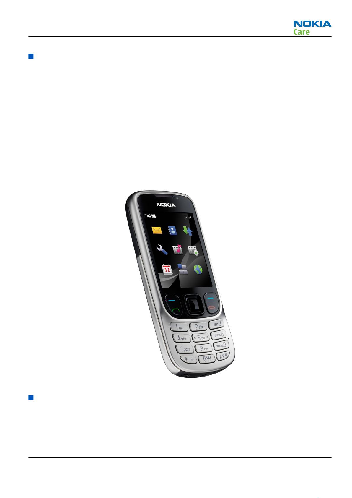
Product selection
RM-443 (Nokia 6303 classic) is a GSM triband handportable phone, supporting EGSM 900/1800/1900 bands
and GPRS/EGPRS data bearers.
For GPRS/EGPRS networks RM-443 is a Class B EGPRS MSC 32 (5 Rx + 3 Tx, max sum 6), which means a maximum
downlink speed of 296 kbit/s and uplink speed of 177.6 kbit/s. RM-443 also supports Dual Transfer Mode
(DTM) for simultaneous voice and packet data connection in GSM/EDGE networks; simple class A, multi slot
class 11, (4 Rx + 3 Tx, max sum 5 ), downlink speed of 177.6 kbit/s and uplink speed of 118.4 kbit/s.
RM-443 is an MMS (Multimedia Messaging Service) enabled multimedia device. The MMS implementation
follows the OMA MMS standard release 1.3. RM-443 also supports Bluetooth 2.1 standard with the stereo
audio profiles.
RM-443 has a large 2.2’’ QVGA (320 x 240 pixels) TFT main display with 16 million colors. The device also has
a 3.2 Megapixel camera with dual LED flash and 8 x digital zoom.
RM-443 supports the 3rd generation S40 UI and S40 OSS web browser, which brings desktop-like Web
browsing experience to mobile devices.
RM-443 also supports MIDP Java 2.0, providing a good platform for compelling 3rd party applications.
Figure 1 View of RM-443
Product features and sales package
Bearers and transport
•
GSM/EDGE Class B, Multi slot class 32
•
GPRS/EGPRS Class B, Multi slot class 32
•
GSM/EDGE Dual Transfer Mode (DTM) class A, multi slot class 11
Issue 2 COMPANY CONFIDENTIAL Page 1 –5
Copyright © 2009 Nokia. All rights reserved.
Page 18

•
DARP (SAIC version 2)
Connectivity
•
Bluetooth 2.1 with stereo audio profiles
•
USB2.0 Full Speed with micro USB interface
•
MicroSD memory card - support up to 4GB (hotswap)
•
3.5 mm AV Connector
•
2 mm DC charger plug
Display
•
Large 2.2’’ QVGA (320x240 pixels) TFT display with 16 million colors
Imaging and video
•
Integrated 3.2 Megapixel camera with dual LED flash, NIPS and smooth 8 x digital zoom
•
Video recording in VGA, CIF, QCIF and subQCIF (15fps)
•
Video player with 3GPP H.263 playback and streaming, recording and MPEG4 playback
RM-443
General information
Music
•
Music Player supporting MP3, MP4, AAC, AAC+, enhanced AAC+, H.263, H.264
•
Ring tones: Video, WAV, MP3, AAC, eAAC+ and 64 polyphonic ringing tones
•
FM stereo radio
Productivity
Context management
•
OMA DRM version 2.0
•
Organizer (Calendar + To-Do + Active Notes)
•
PC Suite
•
Active Standby
•
Local/remote SyncML data sync
•
Web Browser (OSS), Java ™ MIDP 2.0, XHTML browsing over TCP/IP
Messaging
•
Email: Max. message size is 600 kB (sending & receiving)
•
OMA MMS 1.3 (600kB MMS size)
•
Audio Messaging (AMS)
•
Instant Messaging
Voice
•
Speech codec support for HR, FR, EFR and AMR
Add-on software framework
•
Nokia Series 40, 3rd edition
•
Java: MIDP2.0
Additional features
•
Macromedia Flash Lite 3.0
Page 1 –6 COMPANY CONFIDENTIAL Issue 2
Copyright © 2009 Nokia. All rights reserved.
Page 19
RM-443
General information
•
Vibrating alert
•
Reminder light
•
Nokia Maps 1.2 support
Sales package
•
Transceiver RM-443
•
Battery (BL-5CT/1050 mAh)
•
Nokia Charger: AC-8
(AC-6 and CA-100C for China)
•
Nokia wired stereo headset (WH-102)
•
1GB MicroSD card including Nokia Maps
•
USB data cable (CA-101D)
•
User Guide
Product and module list
Module name Type code Notes
Main PWB 2YF
Flash PWB 2AH
Mobile enhancements
Table 1 Audio
Enhancement Type
Audio Adapter (2.5 to 3.5mm) AD-52
Wired headsets HS-16
HS-41
HS-44 (+ AD-45)
HS-45 (+ AD-54)
HS-48
WH-201
WH-500
WH-600
WH-700
WH-800
Issue 2 COMPANY CONFIDENTIAL Page 1 –7
Copyright © 2009 Nokia. All rights reserved.
Page 20
Enhancement Type
Wireless headsets BH-101
BH-102
BH-103
BH-104
BH-200
BH-201
BH-202
BH-208
BH-212
BH-213
BH-215
BH-301
RM-443
General information
BH-501
BH-504
BH-600
BH-602
BH-604
BH-606
BH-700
BH-703
BH-800
BH-803
BH-804
BH-900
BH-902
BH-903
BH-904
Table 2 Car
Enhancement Type
Car installation kit CK-100
CK-300
CK-600
CK-7W
CK-15W
Page 1 –8 COMPANY CONFIDENTIAL Issue 2
Copyright © 2009 Nokia. All rights reserved.
Page 21
RM-443
General information
Enhancement Type
Nokia 500 Auto Navigation PD-14
Universal holder CR-39
CR-82
CR-99
HH-12
HH-17
Wireless plug-in car handsfree HF-33W
HF-200
HF-300
HF-310
HF-510
Table 3 Data
Enhancement Type
MicroSD card, 256MB MU-27
MicroSD card, 512 MB MU-28
MicroSD card, 1 GB MU-22
MicroSD card, 2 GB MU-37
MicroSD card, 4 GB MU-41
MicroSD card, 8 GB MU-43
MicroUSB connectivity adapter cable CA-101, CA-101D
Wireless GPS Module LD-4W
Table 4 Music
Enhancement Type
Wired music speakers MD-4
MD-6
MD-8
Wireless music speakers MD-5W
MD-7W
Issue 2 COMPANY CONFIDENTIAL Page 1 –9
Copyright © 2009 Nokia. All rights reserved.
Page 22
RM-443
General information
Table 5 Power
Enhancement Type
Note: This phone is charged through the smaller charger Nokia standard interface (2.mm plug).
The standard 3.5mm standard charger can be used together with the CA-44 charger adapter.
Battery 1050 mAh Li-Ion BL-5CT
First aid charger DC-8
Mobile charger DC-4
DC-9
DC-11
Travel charger AC-4
AC-5
AC-8
USB charger AC-6C
USB Charger Adapter Cable CA-100
CA-100C
CA-126
Charger adapter CA-44
Technical specifications
General specifications
Unit Dimension (mm) Weight (g) Volume (cc)
Transceiver with BL-5CT
1050 mAh Li-Ion battery
pack
108.8 x 46.2 x 12.9 96 57
Battery endurance
Battery Talk time Stand-by time
BL-5CT 1050 mAh Li-ion Up to 7 hours Up to 18 days
Note: Variation in operation times will occur depending on SIM card, network settings and usage.
Main RF characteristics for GSM900/1800/1900 (triband) and EDGE phones
Table 6 Main RF characteristics
Parameter Unit
Cellular system EGSM900, GSM1800/1900 and EDGE
Page 1 –10 COMPANY CONFIDENTIAL Issue 2
Copyright © 2009 Nokia. All rights reserved.
Page 23
RM-443
General information
Parameter Unit
Rx frequency band EGSM900: 925 - 960 MHz
GSM1800: 1805 - 1880 MHz
GSM1900: 1930 - 1990 MHz
Tx frequency band EGSM900: 880 - 915 MHz
GSM1800: 1710 - 1785 MHz
GSM1900: 1850 - 1910 MHz
Output power GSM900: +5 … +33dBm/3.2mW … 2W
GSM1800: +0 … +30dBm/1.0mW … 1W
GSM1900: +0 … +30dBm/1.0mW … 1W
EDGE output power EDGE900: +5 … +29dBm/3.2mW … 794mW
EDGE1800: +0 … +26dBm/1.0mW … 400mW
EDGE1900:+0 … +26dBm/1.0mW … 400mW
Number of RF channels GSM900: 194
GSM1800: 374
GSM1900: 299
Channel spacing 200 kHz
Number of Tx power levels GSM900: 15
GSM1800: 16
GSM1900: 16
Number of EDGE Tx power levels GSM900 EDGE: 12
GSM1800 EDGE: 14
GSM1900 EDGE: 14
Environmental conditions
Temperature conditions
Environmental condition Ambient temperature Notes
Normal operation
-15oC...+55oC
Specifications fulfilled
Reduced performance
Intermittent operation
No operation or storage
Charging allowed
Issue 2 COMPANY CONFIDENTIAL Page 1 –11
-25oC...-15oC
+55oC...+70oC
-40oC...-15oC
+70oC...+85 oC
<-40oC...>+85oC
-25oC...+50oC
Copyright © 2009 Nokia. All rights reserved.
Operational for shorts periods
only
Operation not guaranteed but an
attempt to operate does not
damage the phone.
No storage or operation: an
attempt may damage the phone.
Page 24

General information
Environmental condition Ambient temperature Notes
RM-443
Long term storage conditions
0oC...+85oC
Humidity
Relative humidity range is 5...95%.
The HW module is not protected against water. Condensed or splashed water might cause malfunction. Any
submerge of the phone will cause permanent damage. Long-term high humidity, with condensation, will
cause permanent damage because of corrosion.
Vibration
The module should withstand the following vibrations:
•
5 - 10 Hz; +10dB / octave
•
10 - 50 Hz; 5.58 m2 / s3 (0.0558 g2/ Hz)
•
50 - 300 Hz; - 10 dB / octave
ESD strength
Conducted discharge is 8 kV (>10 discharges) and air contact 15 kV ( >10 discharges ).
The standard for electrostatic discharge is IEC 61000-4-2, and this device fulfils level 4 requirements.
RoHS
This device uses RoHS compliant components and lead-free soldering process.
Page 1 –12 COMPANY CONFIDENTIAL Issue 2
Copyright © 2009 Nokia. All rights reserved.
Page 25

Nokia Customer Care
2 — Service Devices and
Service Concepts
Issue 2 COMPANY CONFIDENTIAL Page 2 –1
Copyright © 2009 Nokia. All rights reserved.
Page 26

RM-443
Service Devices and Service Concepts
(This page left intentionally blank.)
Page 2 –2 COMPANY CONFIDENTIAL Issue 2
Copyright © 2009 Nokia. All rights reserved.
Page 27

RM-443
Service Devices and Service Concepts
Table of Contents
Service devices........................................................................................................................................................2–5
Product specific devices....................................................................................................................................2–5
FS-121............................................................................................................................................................2–5
MJ-240 ...........................................................................................................................................................2–5
RJ-230 ............................................................................................................................................................2–5
SA-138 ...........................................................................................................................................................2–6
Rework jigs and stencils...................................................................................................................................2–6
RJ-184 ............................................................................................................................................................2–6
ST-61..............................................................................................................................................................2–6
General devices..................................................................................................................................................2–7
AC-33..............................................................................................................................................................2–7
AC-35..............................................................................................................................................................2–7
ACF-8..............................................................................................................................................................2–7
CU-4................................................................................................................................................................2–8
FLS-5 ..............................................................................................................................................................2–9
FPS-10............................................................................................................................................................2–9
FPS-21......................................................................................................................................................... 2–10
PK-1............................................................................................................................................................. 2–10
PKD-1 .......................................................................................................................................................... 2–11
SB-6............................................................................................................................................................. 2–11
SPS-1........................................................................................................................................................... 2–11
SPS-2........................................................................................................................................................... 2–11
SRT-6........................................................................................................................................................... 2–12
SS-46........................................................................................................................................................... 2–12
SS-62........................................................................................................................................................... 2–12
SS-93........................................................................................................................................................... 2–12
SX-4............................................................................................................................................................. 2–12
Cables............................................................................................................................................................... 2–12
CA-101 ........................................................................................................................................................ 2–13
CA-128RS .................................................................................................................................................... 2–13
CA-31D ........................................................................................................................................................ 2–13
CA-35S......................................................................................................................................................... 2–14
CA-89DS ...................................................................................................................................................... 2–14
DAU-9S........................................................................................................................................................ 2–14
PCS-1........................................................................................................................................................... 2–15
XCS-4........................................................................................................................................................... 2–15
XRS-6........................................................................................................................................................... 2–15
Service concepts .................................................................................................................................................. 2–16
POS (Point of Sale) flash concept .................................................................................................................. 2–16
Flash concept with FPS-10............................................................................................................................. 2–17
Flash concept with FPS-21............................................................................................................................. 2–18
CU-4 flash concept with FPS-10..................................................................................................................... 2–19
CU-4 flash concept with FPS-21..................................................................................................................... 2–20
Module jig service concept............................................................................................................................ 2–21
RF testing concept with RF coupler .............................................................................................................. 2–22
Service concept for RF testing and RF/BB tuning........................................................................................ 2–23
Bluetooth testing concept with SB-6 ........................................................................................................... 2–24
List of Tables
Issue 2 COMPANY CONFIDENTIAL Page 2 –3
Copyright © 2009 Nokia. All rights reserved.
Page 28

RM-443
Service Devices and Service Concepts
Table 7 Attenuation values ................................................................................................................................ 2–13
List of Figures
Figure 2 Basic flash concept with FPS-10.......................................................................................................... 2–17
Figure 3 Basic flash concept with FPS-21.......................................................................................................... 2–18
Figure 4 CU-4 flash concept with FPS-10........................................................................................................... 2–19
Figure 5 CU-4 flash concept with FPS-21........................................................................................................... 2–20
Figure 6 Module jig service concept .................................................................................................................. 2–21
Figure 7 RF testing concept with RF coupler .................................................................................................... 2–22
Figure 8 Service concept for RF testing and RF/BB tuning .............................................................................. 2–23
Figure 9 Service concept for RF testing and RF/BB tuning .............................................................................. 2–24
Page 2 –4 COMPANY CONFIDENTIAL Issue 2
Copyright © 2009 Nokia. All rights reserved.
Page 29
RM-443
Service Devices and Service Concepts
Service devices
Product specific devices
The table below gives a short overview of service devices that can be used for testing, error analysis, and
repair of product RM-443. For the correct use of the service devices, and the best effort of workbench setup,
please refer to various concepts.
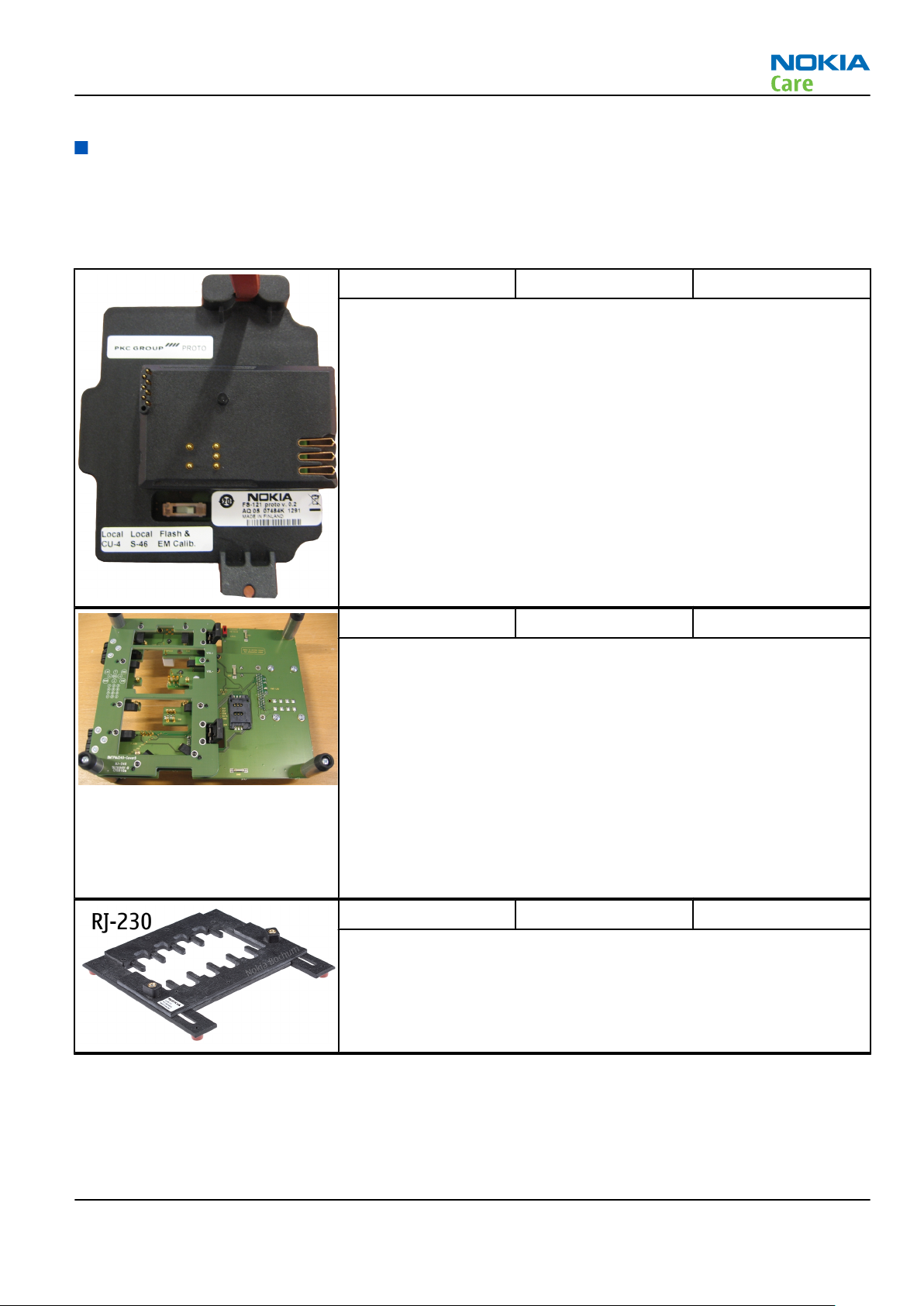
FS-121 Flash adapter
•
FS-121 is equipped with a clip interlock system
•
Provides standardised interface towards Control Unit
•
Provides RF connection using coupler
•
Multiplexing between USB and FBUS media, controlled by VUSB
MJ-240 Module jig MJ-240 is meant for component level troubleshooting.
The jig includes an RF interface for GSM and Bluetooth. In addition, it
has the following features:
•
Provides mechanical interface with the engine module
•
Provides galvanic connection to all needed test pads in module
•
Multiplexing between USB and FBUS media, controlled by Vusb
•
MMC interface
•
Duplicated SIM connector
•
Connector for control unit
•
Access for AV- and USB connectors
RJ-230 Soldering jig RJ-230 is a soldering jig used for soldering and as a rework jig for the
engine module.
Issue 2 COMPANY CONFIDENTIAL Page 2 –5
Copyright © 2009 Nokia. All rights reserved.
Page 30
RM-443
Service Devices and Service Concepts
SA-138 RF coupler SA-138 is an RF coupler for GSM RF testing. It is used together with
SS-46 and SS-62.
The following table shows attenuations from the antenna pads of the
mobile terminal to the SMA connectors of SA-138:
•
Attenuation values for inductive RF coupler SA-138
Band Channel Attenuation RX Attenuation TX
Low 2 2,9
GSM 900
GSM
1800
GSM
1900
Mid 3 2,5
High 4 2,4
Low 5 4,6
Mid 5 4,8
High 5 5,2
Low 6 6,1
Mid 7 6,6
High 8 6,5
Rework jigs and stencils
The table below gives a short overview of service devices that can be used for testing, error analysis, and
repair of product RM-443. For the correct use of the service devices, and the best effort of workbench setup,
please refer to various concepts.
RJ-184 Rework jig RJ-184 is a rework jig used when servicing the microphone (B2150).
It is used together with the ST-61 rework stencil.
ST-61 Rework stencil ST-61 is a rework stencil used when servicing the microphone (B2150).
It is used together with the rework jig RJ-184.
Page 2 –6 COMPANY CONFIDENTIAL Issue 2
Copyright © 2009 Nokia. All rights reserved.
Page 31

RM-443
Service Devices and Service Concepts
General devices
The table below gives a short overview of service devices that can be used for testing, error analysis, and
repair of product RM-443. For the correct use of the service devices, and the best effort of workbench setup,
please refer to various concepts.
AC-33 Power supply Universal power supply for FPS-10; included in the FPS-10 sales
package.
AC-35 Power supply Universal power supply for FPS-21; included in the FPS-21 sales
package.
Input 100V…230V 50Hz…60Hz, output voltage of 12 V and output
current up to 3 A.
ACF-8 Universal power
supply
The ACF-8 universal power supply is used to power FLS-5.
Issue 2 COMPANY CONFIDENTIAL Page 2 –7
Copyright © 2009 Nokia. All rights reserved.
Page 32

RM-443
Service Devices and Service Concepts
CU-4 Control unit CU-4 is a general service tool used with a module jig and/or a flash
adapter. It requires an external 12 V power supply.
The unit has the following features:
•
software controlled via USB
•
EM calibration function
•
Forwards FBUS/Flashbus traffic to/from terminal
•
Forwards USB traffic to/from terminal
•
software controlled BSI values
•
regulated VBATT voltage
•
2 x USB2.0 connector (Hub)
•
FBUS and USB connections supported
When using CU-4, note the special order of connecting cables and
other service equipment:
Instructions
1 Connect a service tool (jig, flash adapter) to CU-4.
2 Connect CU-4 to your PC with a USB cable.
3 Connect supply voltage (12 V)
4 Connect an FBUS cable (if necessary).
5 Start Phoenix service software.
Note: Phoenix enables CU-4 regulators via USB when it is
started.
Reconnecting the power supply requires a Phoenix restart.
Page 2 –8 COMPANY CONFIDENTIAL Issue 2
Copyright © 2009 Nokia. All rights reserved.
Page 33

RM-443
Service Devices and Service Concepts
FLS-5 Flash device FLS-5 is a dongle and flash device incorporated into one package,
developed specifically for POS use.
Note: FLS-5 can be used as an alternative to PKD-1.
FPS-10 Flash prommer FPS-10 interfaces with:
•
PC
•
Control unit
•
Flash adapter
•
Smart card
FPS-10 flash prommer features:
•
Flash functionality for BB5 and DCT-4 terminals
•
Smart Card reader for SX-2 or SX-4
•
USB traffic forwarding
•
USB to FBUS/Flashbus conversion
•
LAN to FBUS/Flashbus and USB conversion
•
Vusb output switchable by PC command
FPS-10 sales package includes:
•
FPS-10 prommer
•
Power Supply with 5 country specific cords
•
USB cable
Note: FPS-21 is substitute FPS-10 if FPS-10 has not been set
up.
Issue 2 COMPANY CONFIDENTIAL Page 2 –9
Copyright © 2009 Nokia. All rights reserved.
Page 34

Service Devices and Service Concepts
FPS-21 Flash prommer
FPS-21 sales package:
•
FPS-21 prommer
•
AC-35 power supply
•
CA-31D USB cable
FPS-21 interfaces:
Front
•
Service cable connector
Provides Flashbus, USB and VBAT connections to a mobile device.
•
SmartCard socket
A SmartCard is needed to allow DCT-4 generation mobile device
programming.
Rear
•
DC power input
For connecting the external power supply (AC-35).
•
Two USB A type ports (USB1/USB3)
Can be used, for example, for connecting external storage memory
devices or mobile devices
•
One USB B type device connector (USB2)
For connecting a PC.
•
Phone connector
Service cable connection for connecting Flashbus/FLA.
•
Ethernet RJ45 type socket (LAN)
For connecting the FPS-21 to LAN.
Inside
•
Four SD card memory slots
For internal storage memory.
Note: In order to access the SD memory card slots inside
FPS-21, the prommer needs to be opened by removing the
front panel, rear panel and heatsink from the prommer body.
Note: FPS-10 can be used for flashing instead of FPS-21 if
necessary.
RM-443
PK-1 Software protection
key
PK-1 is a hardware protection key with a USB interface. It has the same
functionality as the PKD-1 series dongle.
PK-1 is meant for use with a PC that does not have a series interface.
To use this USB dongle for security service functions please register
the dongle in the same way as the PKD-1 series dongle.
Page 2 –10 COMPANY CONFIDENTIAL Issue 2
Copyright © 2009 Nokia. All rights reserved.
Page 35

RM-443
Service Devices and Service Concepts
PKD-1 SW security device SW security device is a piece of hardware enabling the use of the
service software when connected to the parallel (LPT) port of the PC.
Without the device, it is not possible to use the service software.
Printer or any such device can be connected to the PC through the
device if needed.
SB-6 Bluetooth test and
interface box (sales
package)
The SB-6 test box is a generic service device used to perform Bluetooth
bit error rate (BER) testing, and establishing cordless FBUS connection
via Bluetooth. An ACP-8x charger is needed for BER testing and an
AXS-4 cable in case of cordless interface usage testing .
Sales package includes:
•
SB-6 test box
•
Installation and warranty information
SPS-1 Soldering Paste
Spreader
The SPS-1 allows spreading of solder to the LGA components pads over
the rework stencils.
Note: Existing solder paste stencils and component holder
jigs will be supported until January 2009. For all new parts
needing solder paste support after January 1, 2009, please
contact your solder machine manufacturer for the universal
solutions for solder paste application for rework purposes.
SPS-2 Soldering paste
spreader
Note: Existing solder paste stencils and component holder
jigs will be supported until January 2009. For all new parts
needing solder paste support after January 1, 2009, please
contact your solder machine manufacturer for the universal
solutions for solder paste application for rework purposes.
Issue 2 COMPANY CONFIDENTIAL Page 2 –11
Copyright © 2009 Nokia. All rights reserved.
Page 36

RM-443
Service Devices and Service Concepts
SRT-6 Opening tool SRT-6 is used to open phone covers.
Note: The SRT-6 is included in the Nokia Standard Toolkit.
SS-46 Interface adapter SS-46 acts as an interface adapter between the flash adapter and
FPS-10.
SS-62 Generic flash adapter
base for BB5
•
generic base for flash adapters and couplers
•
SS-62 equipped with a clip interlock system
•
provides standardised interface towards Control Unit
•
provides RF connection using galvanic connector or coupler
•
multiplexing between USB and FBUS media, controlled by VUSB
SS-93 Opening tool SS-93 is used for opening JAE connectors.
Note: The SS-93 is included in Nokia Standard Toolkit.
SX-4 Smart card SX-4 is a BB5 security device used to protect critical features in tuning
and testing.
SX-4 is also needed together with FPS-10 when DCT-4 phones are
flashed.
Cables
The table below gives a short overview of service devices that can be used for testing, error analysis, and
repair of product RM-443. For the correct use of the service devices, and the best effort of workbench setup,
please refer to various concepts.
Page 2 –12 COMPANY CONFIDENTIAL Issue 2
Copyright © 2009 Nokia. All rights reserved.
Page 37

RM-443
Service Devices and Service Concepts
CA-101 Micro USB cable The CA-101 is a USB-to-microUSB data cable that allows connections
between the PC and the phone.
CA-128RS RF tuning cable Product-specific adapter cable for RF tuning.
•
Table 7 Attenuation values
Band Attenuation Rx
GSM850/900 0.30 dB
GSM1800 0.40 dB
GSM1900 0.45 dB
WLAN 2.4GHz 0.40 dB
CA-31D USB cable The CA-31D USB cable is used to connect FPS-10 or FPS-11 to a PC. It is
included in the FPS-10 and FPS-11 sales packages.
Issue 2 COMPANY CONFIDENTIAL Page 2 –13
Copyright © 2009 Nokia. All rights reserved.
Page 38

RM-443
Service Devices and Service Concepts
CA-35S Power cable CA-35S is a power cable for connecting, for example, the FPS-10 flash
prommer to the Point-Of-Sales (POS) flash adapter.
CA-89DS Cable Provides VBAT and Flashbus connections to mobile device
programming adapters.
DAU-9S MBUS cable The MBUS cable DAU-9S has a modular connector and is used, for
example, between the PC's serial port and module jigs, flash adapters
or docking station adapters.
Note: Docking station adapters valid for DCT4 products.
Page 2 –14 COMPANY CONFIDENTIAL Issue 2
Copyright © 2009 Nokia. All rights reserved.
Page 39

RM-443
Service Devices and Service Concepts
PCS-1 Power cable The PCS-1 power cable (DC) is used with a docking station, a module
jig or a control unit to supply a controlled voltage.
XCS-4 Modular cable XCS-4 is a shielded (one specially shielded conductor) modular cable
for flashing and service purposes.
XRS-6 RF cable The RF cable is used to connect, for example, a module repair jig to
the RF measurement equipment.
SMA to N-Connector approximately 610 mm.
Attenuation for:
•
GSM850/900: 0.3+-0.1 dB
•
GSM1800/1900: 0.5+-0.1 dB
•
WLAN: 0.6+-0.1dB
Issue 2 COMPANY CONFIDENTIAL Page 2 –15
Copyright © 2009 Nokia. All rights reserved.
Page 40

Service concepts
POS (Point of Sale) flash concept
RM-443
Service Devices and Service Concepts
Type Description
Product specific tools
BL-5CT Battery
Other tools
FLS-5 POS flash dongle
PC with Phoenix service software
Cables
CA-101 Micro USB cable
Page 2 –16 COMPANY CONFIDENTIAL Issue 2
Copyright © 2009 Nokia. All rights reserved.
Page 41

RM-443
Service Devices and Service Concepts
Flash concept with FPS-10
Figure 2 Basic flash concept with FPS-10
Type Description
Product specific devices
FS-121 Flash adapter
Other devices
FPS-10 Flash prommer box
PKD-1/PK-1 SW security device
SS-46 Interface adapter
PC with Phoenix service software
Cables
XCS-4 Modular cable
CA-35S Power cable
USB cable
Issue 2 COMPANY CONFIDENTIAL Page 2 –17
Copyright © 2009 Nokia. All rights reserved.
Page 42

Flash concept with FPS-21
RM-443
Service Devices and Service Concepts
Figure 3 Basic flash concept with FPS-21
Type Description
Product specific devices
FS-121 Flash adapter
Other devices
FPS-21 Flash prommer box
AC-35 Power supply
PK-1/PKD-1 SW security device
SS-46 Interface adapter
PC with Phoenix service software
Cables
CA-89DS Service cable
USB cable
Page 2 –18 COMPANY CONFIDENTIAL Issue 2
Copyright © 2009 Nokia. All rights reserved.
Page 43

RM-443
Service Devices and Service Concepts
CU-4 flash concept with FPS-10
Figure 4 CU-4 flash concept with FPS-10
Type Description
Product specific devices
FS-121 Flash adapter
Other devices
CU-4 Control unit
FPS-10 Flash prommer box
PKD-1/PK-1 SW security device
SS-62 Flash adapter base
SX-4 Smart card
PC with Phoenix service software
Cables
PCS-1 Power cable
XCS-4 Modular cable
Standard USB cable
USB cable
Issue 2 COMPANY CONFIDENTIAL Page 2 –19
Copyright © 2009 Nokia. All rights reserved.
Page 44

CU-4 flash concept with FPS-21
RM-443
Service Devices and Service Concepts
Figure 5 CU-4 flash concept with FPS-21
Type Description
Product specific devices
FS-121 Flash adapter
Other devices
CU-4 Control unit
FPS-21 Flash prommer box
AC-35 Power supply
PK-1/PKD-1 SW security device
SS-62 Flash adapter base
SX-4 Smart card (for DCT-4 generation mobile device programming)
PC with Phoenix service software
Cables
PCS-1 Power cable
CA-89DS Service cable
Standard USB cable
Page 2 –20 COMPANY CONFIDENTIAL Issue 2
Copyright © 2009 Nokia. All rights reserved.
Page 45

RM-443
Service Devices and Service Concepts
Type Description
USB cable
Module jig service concept
Figure 6 Module jig service concept
Type Description
Phone specific tools
MJ-240 Module jig
Other tools
CU-4 Control unit
FPS-10 Flash prommer box
PKD-1/PK-1 SW security device
SX-4 Smart card
PC with Phoenix service software
Measurement equipment
Cables
CA-128RS RF service cable (product-specific adapter cable)
PCS-1 DC power cable
XCS-4 Modular cable
XRS-6 RF cable
Issue 2 COMPANY CONFIDENTIAL Page 2 –21
Copyright © 2009 Nokia. All rights reserved.
Page 46

Type Description
USB cable
GPIB control cable
RF testing concept with RF coupler
RM-443
Service Devices and Service Concepts
Figure 7 RF testing concept with RF coupler
Type Description
Product specific devices
FS-121 Flash adapter
SA-138 RF coupler
Other devices
CU-4 Control unit
SX-4 Smart card
FPS-10 Flash prommer box
PKD-1/PK-1 SW security device
SS-62 Flash adapter base
Measurement equipment
PC with Phoenix service software
Cables
Page 2 –22 COMPANY CONFIDENTIAL Issue 2
Copyright © 2009 Nokia. All rights reserved.
Page 47

RM-443
Service Devices and Service Concepts
Type Description
PCS-1 Power cable
XCS-4 Modular cable
XRS-6 RF cable
GPIB control cable
USB cable
Service concept for RF testing and RF/BB tuning
Figure 8 Service concept for RF testing and RF/BB tuning
Type Description
Product specific devices
MJ-240 Module jig
Other devices
CU-4 Control unit
PK-1/PKD-1 SW security device
SX-4 Smart card
Measurement equipment
Smart card reader
Issue 2 COMPANY CONFIDENTIAL Page 2 –23
Copyright © 2009 Nokia. All rights reserved.
Page 48

Type Description
PC with Phoenix service software
Cables
DAU-9S MBUS cable
PCS-1 DC power cable
XRS-6 RF cable
GPIB control cable
USB cable
Bluetooth testing concept with SB-6
RM-443
Service Devices and Service Concepts
Figure 9 Service concept for RF testing and RF/BB tuning
Type Description
Product specific devices
FS-121 Flash adapter
Other devices
CU-4 Control unit
SS-62 Flash adapter base
PK-1 SW security device
SX-4 Smart card
SB-6 Bluetooth test and interface box
Page 2 –24 COMPANY CONFIDENTIAL Issue 2
Copyright © 2009 Nokia. All rights reserved.
Page 49

RM-443
Service Devices and Service Concepts
Type Description
Smart card reader
PC with Phoenix service software
Cables
DAU-9S MBUS cable
PCS-1 DC power cable
USB cable
Issue 2 COMPANY CONFIDENTIAL Page 2 –25
Copyright © 2009 Nokia. All rights reserved.
Page 50

RM-443
Service Devices and Service Concepts
(This page left intentionally blank.)
Page 2 –26 COMPANY CONFIDENTIAL Issue 2
Copyright © 2009 Nokia. All rights reserved.
Page 51

Nokia Customer Care
3 — BB Troubleshooting and
Manual Tuning Guide
Issue 2 COMPANY CONFIDENTIAL Page 3 –1
Copyright © 2009 Nokia. All rights reserved.
Page 52

RM-443
BB Troubleshooting and Manual Tuning Guide
(This page left intentionally blank.)
Page 3 –2 COMPANY CONFIDENTIAL Issue 2
Copyright © 2009 Nokia. All rights reserved.
Page 53

RM-443
BB Troubleshooting and Manual Tuning Guide
Table of Contents
Baseband self tests in Phoenix .............................................................................................................................3–5
Power and charging troubleshooting..................................................................................................................3–7
Dead or jammed device troubleshooting.......................................................................................................3–7
General power checking...................................................................................................................................3–9
Charging troubleshooting ............................................................................................................................. 3–10
Interface troubleshooting .................................................................................................................................. 3–11
Flash programming fault troubleshooting.................................................................................................. 3–11
Combo memory troubleshooting ................................................................................................................. 3–14
MicroSD card troubleshooting....................................................................................................................... 3–14
USB interface troubleshooting...................................................................................................................... 3–16
SIM card troubleshooting .............................................................................................................................. 3–17
User interface troubleshooting.......................................................................................................................... 3–18
Keypad and side key troubleshooting ......................................................................................................... 3–18
Keymat backlight and reminder light troubleshooting ............................................................................. 3–19
Display module troubleshooting.................................................................................................................. 3–19
General instructions for display troubleshooting.................................................................................. 3–19
Display module troubleshooting............................................................................................................. 3–21
Ambient Light Sensor troubleshooting and re-calibration............................................................................. 3–21
Introduction to ALS troubleshooting and re-calibration ........................................................................... 3–21
Ambient Light Sensor calibration................................................................................................................. 3–23
ALS functionality check............................................................................................................................. 3–23
Calibrating ALS........................................................................................................................................... 3–24
Camera troubleshooting..................................................................................................................................... 3–26
Camera troubleshooting................................................................................................................................ 3–26
Camera hardware troubleshooting.............................................................................................................. 3–26
Camera flash LED troubleshooting ............................................................................................................... 3–28
Audio troubleshooting........................................................................................................................................ 3–29
Audio troubleshooting test instructions...................................................................................................... 3–29
Internal earpiece troubleshooting ............................................................................................................... 3–32
Internal microphone troubleshooting......................................................................................................... 3–33
Internal handsfree (IHF) troubleshooting.................................................................................................... 3–33
External earpiece troubleshooting............................................................................................................... 3–34
External microphone troubleshooting......................................................................................................... 3–35
Acoustics troubleshooting............................................................................................................................. 3–35
Introduction to acoustics troubleshooting ............................................................................................ 3–35
Earpiece troubleshooting......................................................................................................................... 3–37
IHF troubleshooting.................................................................................................................................. 3–38
Microphone troubleshooting ................................................................................................................... 3–39
Vibra troubleshooting.................................................................................................................................... 3–40
Bluetooth and FM radio troubleshooting ......................................................................................................... 3–41
Introduction to Bluetooth/FM Radio troubleshooting ............................................................................... 3–41
Bluetooth settings for Phoenix..................................................................................................................... 3–43
Bluetooth self tests in Phoenix..................................................................................................................... 3–44
Bluetooth troubleshooting ........................................................................................................................... 3–45
FM radio troubleshooting.............................................................................................................................. 3–45
Baseband manual tuning guide......................................................................................................................... 3–47
Certificate restoring ....................................................................................................................................... 3–47
Energy management calibration.................................................................................................................. 3–47
Issue 2 COMPANY CONFIDENTIAL Page 3 –3
Copyright © 2009 Nokia. All rights reserved.
Page 54

RM-443
BB Troubleshooting and Manual Tuning Guide
List of Tables
Table 8 Display module troubleshooting cases................................................................................................ 3–19
Table 9 Pixel defects ........................................................................................................................................... 3–20
Table 10 Calibration value limits ....................................................................................................................... 3–48
List of Figures
Figure 10 Flashing pic 1. Take single trig measurement for the rise of the BSI signal................................ 3–12
Figure 11 Flashing pic 2. Take single trig measurement for the rise of the BSI signal................................ 3–13
Figure 12 Ambient Light Sensor location.......................................................................................................... 3–22
Figure 13 ALS light guide location..................................................................................................................... 3–22
Figure 14 Single-ended output waveform of the Ext_in_HP_out measurement when earpiece is
connected. ................................................................................................................................................. 3–30
Figure 15 Single-ended output waveform of the Ext_in_IHF_out out loop measurement when speaker
is connected (measured at speaker pads). No filter is used. ............................................................... 3–31
Figure 16 Single-ended output waveform of the Ext_in_Ext_out loop........................................................... 3–31
Figure 17 Single-ended output waveform of the Digital_stereo_microphone_in_Ext_out loop.................. 3–31
Figure 18 Bluetooth antenna location .............................................................................................................. 3–41
Figure 19 Bluetooth and FM radio component layout..................................................................................... 3–42
Figure 20 BER test result..................................................................................................................................... 3–43
Figure 21 Bluetooth self tests in Phoenix......................................................................................................... 3–44
Page 3 –4 COMPANY CONFIDENTIAL Issue 2
Copyright © 2009 Nokia. All rights reserved.
Page 55

RM-443
BB Troubleshooting and Manual Tuning Guide
Baseband self tests in Phoenix
Context
Always start the troubleshooting procedure by running the Phoenix self tests. If a test fails, please follow the
diagram below.
If the phone is dead and you cannot perform the self tests, go to
Dead or jammed device troubleshooting.
Issue 2 COMPANY CONFIDENTIAL Page 3 –5
Copyright © 2009 Nokia. All rights reserved.
Page 56

Troubleshooting flow
RM-443
BB Troubleshooting and Manual Tuning Guide
Page 3 –6 COMPANY CONFIDENTIAL Issue 2
Copyright © 2009 Nokia. All rights reserved.
Page 57

RM-443
BB Troubleshooting and Manual Tuning Guide
Power and charging troubleshooting
Dead or jammed device troubleshooting
Troubleshooting flow
Issue 2 COMPANY CONFIDENTIAL Page 3 –7
Copyright © 2009 Nokia. All rights reserved.
Page 58

Troubleshooting flow
RM-443
BB Troubleshooting and Manual Tuning Guide
Page 3 –8 COMPANY CONFIDENTIAL Issue 2
Copyright © 2009 Nokia. All rights reserved.
Page 59

RM-443
BB Troubleshooting and Manual Tuning Guide
General power checking
Check the following voltages:
Signal name Regulator Sleep Idle Nominal
voltage
VIO AVILMA ON ON 1.82 Memory, I/Os,
VBACK AVILMA ON ON 2.5 Back-up
VSIM1 AVILMA ON ON 1.8/3.0 SIM card
VDRAM AVILMA ON ON 1.82 SDRAM
VAUX AVILMA ON ON 2.78 Camera,
VR1 AVILMA OFF ON 2.5 Crystal
VRFC AVILMA OFF ON 1.8 RAPS
VRCP1 AVILMA 4.75 To RF parts RF active
VREF AVILMA ON ON 1.35 RF reference
VCORE BETTY ON ON 1.05
1.25
1.35
1.40
Main user Notes
Display
battery
Display
oscillators, RFIC
RAPS digital
VOUT BETTY OFF OFF 2.5 Accessory
connected
VMMC KMBGN000A/
N3200
VLED_POS TPS61061/
N2301
OFF OFF 2.850 Internal
memory
OFF OFF 14.5 LCD Backlight Disabled in
Disabled in
sleep
sleep
Issue 2 COMPANY CONFIDENTIAL Page 3 –9
Copyright © 2009 Nokia. All rights reserved.
Page 60

Charging troubleshooting
Troubleshooting flow
RM-443
BB Troubleshooting and Manual Tuning Guide
Page 3 –10 COMPANY CONFIDENTIAL Issue 2
Copyright © 2009 Nokia. All rights reserved.
Page 61

RM-443
BB Troubleshooting and Manual Tuning Guide
Interface troubleshooting
Flash programming fault troubleshooting
Part 1
Issue 2 COMPANY CONFIDENTIAL Page 3 –11
Copyright © 2009 Nokia. All rights reserved.
Page 62

Part 2
RM-443
BB Troubleshooting and Manual Tuning Guide
Figure 10 Flashing pic 1. Take single trig measurement for the rise of the BSI signal.
Page 3 –12 COMPANY CONFIDENTIAL Issue 2
Copyright © 2009 Nokia. All rights reserved.
Page 63

RM-443
BB Troubleshooting and Manual Tuning Guide
Figure 11 Flashing pic 2. Take single trig measurement for the rise of the BSI signal.
Issue 2 COMPANY CONFIDENTIAL Page 3 –13
Copyright © 2009 Nokia. All rights reserved.
Page 64

Combo memory troubleshooting
Troubleshooting flow
RM-443
BB Troubleshooting and Manual Tuning Guide
Page 3 –14 COMPANY CONFIDENTIAL Issue 2
Copyright © 2009 Nokia. All rights reserved.
Page 65
RM-443
BB Troubleshooting and Manual Tuning Guide
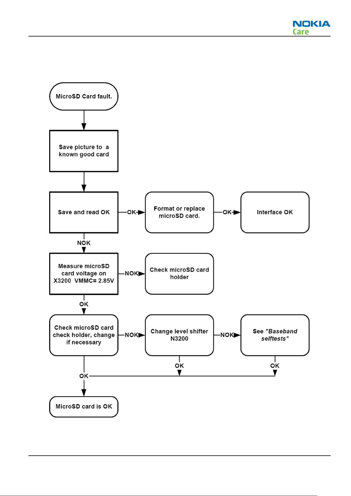
MicroSD card troubleshooting
Troubleshooting flow
Issue 2 COMPANY CONFIDENTIAL Page 3 –15
Copyright © 2009 Nokia. All rights reserved.
Page 66

USB interface troubleshooting
Troubleshooting flow
RM-443
BB Troubleshooting and Manual Tuning Guide
Page 3 –16 COMPANY CONFIDENTIAL Issue 2
Copyright © 2009 Nokia. All rights reserved.
Page 67

RM-443
BB Troubleshooting and Manual Tuning Guide
SIM card troubleshooting
Troubleshooting flow
Issue 2 COMPANY CONFIDENTIAL Page 3 –17
Copyright © 2009 Nokia. All rights reserved.
Page 68

RM-443
BB Troubleshooting and Manual Tuning Guide
User interface troubleshooting
Keypad and side key troubleshooting
Context
If one or more keys are stuck, so that the key does not react when a keydome or the side key is pressed, the
failure is caused by mechanical reasons (dirt, rust, mechanical damage, etc.)
If the failure mode is not clear, start with the Keyboard test in Phoenix.
Troubleshooting flow
Page 3 –18 COMPANY CONFIDENTIAL Issue 2
Copyright © 2009 Nokia. All rights reserved.
Page 69

RM-443
BB Troubleshooting and Manual Tuning Guide
Keymat backlight and reminder light troubleshooting
Troubleshooting flow
Display module troubleshooting
General instructions for display troubleshooting
Context
•
The display is in a normal mode when the phone is in active use.
•
Display is in a sleep mode when the phone is in the screen saver mode.
Table 8 Display module troubleshooting cases
Display blank There is no image on the display. The display looks
the same when the phone is on as it does when the
phone is off. The backlight can be on in some cases.
Issue 2 COMPANY CONFIDENTIAL Page 3 –19
Copyright © 2009 Nokia. All rights reserved.
Page 70

RM-443
BB Troubleshooting and Manual Tuning Guide
Image on the display not correct Image on the display can be corrupted or a part of
the image can be missing. If a part of the image is
missing, change the display module. If the image is
otherwise corrupted, follow the appropriate
troubleshooting diagram.
Backlight dim or not working at all Backlight LED components are inside the display
module. Backlight failure can also be in the
connector or in the backlight power source in the
main engine of the phone.
This means that in case the display is working
(image OK), the backlight is faulty.
Visual defects (pixel) Pixel defects can be checked by controlling the
display with Phoenix. Use both colours, black and
white, on a full screen.
The display may have some random pixel defects
that are acceptable for this type of display. The
criteria when pixel defects are regarded as a display
failure, resulting in a replacement of the display, are
presented the following table.
Table 9 Pixel defects
Item White dot defect Black dot
defect
1 Defect counts R G B White Dot
Total
1 1 1 1
2 Combined
defect counts
Not allowed.
Two single dot defects that are within 5 mm of each other should be
interpreted as combined dot defect.
1 1
Total
Steps
1. Verify with a working display that the fault is not on the display module itself.
The display module cannot be repaired.
2. Check that the cellular engine is working normally.
i To check the functionality, connect the phone to a docking station.
ii Start
iii Read the phone information to check that also the application engine is functioning normally (you
3. Proceed to the display troubleshooting flowcharts.
Use the Display Test tool in
Phoenix
should be able to read the APE ID).
service software.
Phoenix
to find the detailed fault mode.
Page 3 –20 COMPANY CONFIDENTIAL Issue 2
Copyright © 2009 Nokia. All rights reserved.
Page 71

RM-443
BB Troubleshooting and Manual Tuning Guide
Display module troubleshooting
Troubleshooting flow
Ambient Light Sensor troubleshooting and re-calibration
Introduction to ALS troubleshooting and re-calibration
If the Ambient Light Sensor (ALS) functionality is inoperative, check the sensor (N2460) located at the top
side of the main PWB. If necessary, change sensor.
Issue 2 COMPANY CONFIDENTIAL Page 3 –21
Copyright © 2009 Nokia. All rights reserved.
Page 72

BB Troubleshooting and Manual Tuning Guide
Figure 12 Ambient Light Sensor location
Also, check the ALS light guide located at the top side of the UI shielding assembly.
RM-443
Figure 13 ALS light guide location
After replacing the ALS sensor, or if the calibration values of the sensor are lost or for some other reason, ALS
calibration is required. For more information, see ALS functionality check (page 3–23) and Calibrating ALS
(page 3–24).
Note: ALS calibration is also required for Light SWAP Engines, because ALS is not factory calibrated
for Light SWAP.
When executing the ALS calibration, a reference phone that includes calibrated ALS is required. The ALS retuning instructions show why the reference phone is needed.
Note: Make sure that you have completed the display and keyboard backlights troubleshooting
before starting the ALS troubleshooting.
There is an Ambient Light Sensor window in the Phoenix Display Test tool, which shows the luminance value.
The correct luminance in darkness is <20 lx, and in an office environment 100-2000 lx.
Page 3 –22 COMPANY CONFIDENTIAL Issue 2
Copyright © 2009 Nokia. All rights reserved.
Page 73

RM-443
BB Troubleshooting and Manual Tuning Guide
Note: The luminance value depends heavily on the light source and the angle of the phone against
the light source, so the values above can only be used as a rough guideline. Phoenix has an ambient
light sensor calibration tool for changing the calibration values.
Ambient Light Sensor calibration
ALS functionality check
Steps
1. Connect the phone to
the ambient light visible to ALS is stable. The light quide of the ALS is located on the upper part of the
phone’s front cover, right next to the secondary camera.
2. Scan product on Phoenix (CTRL+R)
3. Choose Testing→Display test.
Phoenix
, start the
Phoenix
software, and set the phone (e.g. on the table) so that
4. Open the Lights tab, and check the Ambient light sensor check box. Click the Read button in order to get
the reference ambient light value. Cover the sensor and click Read again. When covered, the luminance
reading should be less than after clicking Read without covering the sensor.
5. If the component does not give any reading or the reading does not change when sensor is/is not covered,
replace the part.
Note: The ALS module is located on the main PWB. ALS calibration must always be done when the
main PWB is changed. Also, if the ALS calibration values are lost from the phone, ALS needs to be
recalibrated.
The ALS calibration procedure requires a reference phone with a calibrated ALS.
Issue 2 COMPANY CONFIDENTIAL Page 3 –23
Copyright © 2009 Nokia. All rights reserved.
Page 74

RM-443
BB Troubleshooting and Manual Tuning Guide
Calibrating ALS
Context
Before doing the manual ALS calibration, test the following default values:
1 Check the Use default values only box from the Ambient Light Sensor Calibration window
2 Click Write
3 Open the Display Test window
4 Read the luminance value from the Display Test window. If the luminance value differs a lot (difference
max. +- 10%) when compared to the reference phone, perform a manual ALS tuning procedure by
following the instructions below.
Steps
1. Connect the phone to
the ambient light visible to ALS is stable. The light quide of the ALS is located on the upper part of the
phone’s front cover, right next to the secondary camera.
2. Scan product on Phoenix (CTRL+R)
3. Choose Tuning→Ambient Light Sensor Calibration.
Phoenix
, start the
Phoenix
software, and set the phone (e.g. on the table) so that
4. Uncheck the Use default values only check box, click the Read button to get the AD-Count values for
Channel 0 and Channel 1, and write them down.
Note: In the example graphic the reference phone values are: Channel 0=3001 and Channel 1=337
5. Repeat steps 1-4 for the phone to be calibrated.
Note: Make sure the phone to be calibrated is located in the same place as the reference phone was
when luminance reading was taken.
Page 3 –24 COMPANY CONFIDENTIAL Issue 2
Copyright © 2009 Nokia. All rights reserved.
Page 75

RM-443
BB Troubleshooting and Manual Tuning Guide
6. Calculate and write down co-efficient value by division:
7. To calibrate ALS, the value in the Reference Level textbox needs to be adjusted for both channels until
the Co-efficient calculated by Phoenix equals the values calculated in step 6. Click Calibrate after each
try (and uncheck the Use default values only check box).
8. Calibration is done when the Co-efficient is equal to the co-efficient value calculated in step 6.
Note: Decimal numbers should be used in the iteration in order to achieve adequate precision (e.g.
200.2455)
9. Use Phoenix (Testing→Display test→Lights tab) to verify the calibration by reading the luminance value
for both the reference phone and calibrated phone.
Note: Remember that the illuminance readings for the reference and calibrated phones must be
done in the same ambient light conditions. If the illuminance values differ more than +- 10%, repeat
the whole ALS calibration procedure.
10. To end the calibration, click Close.
Issue 2 COMPANY CONFIDENTIAL Page 3 –25
Copyright © 2009 Nokia. All rights reserved.
Page 76

Camera troubleshooting
Camera troubleshooting
Troubleshooting flow
RM-443
BB Troubleshooting and Manual Tuning Guide
Page 3 –26 COMPANY CONFIDENTIAL Issue 2
Copyright © 2009 Nokia. All rights reserved.
Page 77

RM-443
BB Troubleshooting and Manual Tuning Guide
Camera hardware troubleshooting
Troubleshooting flow
Issue 2 COMPANY CONFIDENTIAL Page 3 –27
Copyright © 2009 Nokia. All rights reserved.
Page 78

Camera flash LED troubleshooting
Troubleshooting flow
RM-443
BB Troubleshooting and Manual Tuning Guide
Page 3 –28 COMPANY CONFIDENTIAL Issue 2
Copyright © 2009 Nokia. All rights reserved.
Page 79

RM-443
BB Troubleshooting and Manual Tuning Guide
Audio troubleshooting
Audio troubleshooting test instructions
Single-ended external earpiece and differential internal earpiece outputs can be measured either with a
single-ended or a differential probe.
When measuring with a single-ended probe each output is measured against the ground.
Internal handsfree output is measured using a current probe, if a special low-pass filter designed for
measuring a digital amplifier is not available. Note also that when using a current probe, the input signal
frequency must be set to 2kHz.
The input signal for each loop test can be either single-ended or differential. Exception to this is a digital
microphone, which needs input signal from an external sound source (laptop speaker) to playback eg. 1kHz
sine wave from 5cm distance.
Required equipment
The following equipment is needed for the tests:
•
Oscilloscope
•
Function generator (sine waveform)
•
Current probe (Internal handsfree PWM output measurement)
•
Phoenix service software
•
Battery voltage 3.7V
•
Sound source (laptop speaker or B&K type 4231 calibrator)
Test procedure
Audio can be tested using the Phoenix audio routings option. Three different audio loop paths can be
activated:
•
External microphone to Internal earpiece
•
External microphone to Internal handsfree speaker
•
Digital stereo microphone to External earpiece
Each audio loop sets routing from the specified input to the specified output enabling a quick in-out test.
Loop path gains are fixed and they cannot be changed using Phoenix. Correct pins and signals for each test
are presented in the following table.
Phoenix audio loop tests and test results
The results presented in the table apply when no accessory is connected and battery voltage is set to 3.7V.
Earpiece, internal microphone and speaker are in place during measurement. Applying a headset accessory
during measurement causes a significant drop in measured quantities.
The gain values presented in the table apply for a differential output vs. single-ended/differential input.
Issue 2 COMPANY CONFIDENTIAL Page 3 –29
Copyright © 2009 Nokia. All rights reserved.
Page 80

RM-443
BB Troubleshooting and Manual Tuning Guide
Loop test Input
terminal
External Mic to
External
Earpiece
External Mic to
Internal
Earpiece
External Mic to
Internal
handsfree
Digital Mic to
External
Earpiece
HS_MIC &
GND
HS_MIC &
GND
HS_MIC &
GND
Acoustical
input, 1kHz
sine wave
Output
terminal
HS_EAR_L &
GND
HS_EAR_R &
GND
EarP & GND 0 100 100 1.2 NA
EarN & GND
J2103 &
J2104
J2101 &
J2102
HS_EAR_L &
GND
HS_EAR_R &
GND
Path
gain
[dB]
(fixed)
12 140 1.9Vpp 1.2 NA
6 200 500
NA 94 dB
Input
voltage
[mVp-
p]
SPL
Output
voltage
[mVp-p]
100 NA
Output
DC level
[V]
current [mA]
Output
Measurement data
Earpiece signal
Figure 14 Single-ended output waveform of the Ext_in_HP_out measurement when earpiece is connected.
Integrated handsfree signal
Page 3 –30 COMPANY CONFIDENTIAL Issue 2
Copyright © 2009 Nokia. All rights reserved.
Page 81

RM-443
BB Troubleshooting and Manual Tuning Guide
Figure 15 Single-ended output waveform of the Ext_in_IHF_out out loop measurement when speaker is connected
(measured at speaker pads). No filter is used.
External output from AV
Figure 16 Single-ended output waveform of the Ext_in_Ext_out loop.
External output from AV (acoustic input)
Figure 17 Single-ended output waveform of the Digital_stereo_microphone_in_Ext_out loop.
Issue 2 COMPANY CONFIDENTIAL Page 3 –31
Copyright © 2009 Nokia. All rights reserved.
Page 82

Internal earpiece troubleshooting
Troubleshooting flow
RM-443
BB Troubleshooting and Manual Tuning Guide
Page 3 –32 COMPANY CONFIDENTIAL Issue 2
Copyright © 2009 Nokia. All rights reserved.
Page 83

RM-443
BB Troubleshooting and Manual Tuning Guide
Internal microphone troubleshooting
Troubleshooting flow
Issue 2 COMPANY CONFIDENTIAL Page 3 –33
Copyright © 2009 Nokia. All rights reserved.
Page 84

Internal handsfree (IHF) troubleshooting
Troubleshooting flow
RM-443
BB Troubleshooting and Manual Tuning Guide
Page 3 –34 COMPANY CONFIDENTIAL Issue 2
Copyright © 2009 Nokia. All rights reserved.
Page 85

RM-443
BB Troubleshooting and Manual Tuning Guide
External earpiece troubleshooting
Troubleshooting flow
External microphone troubleshooting
Troubleshooting flow
Acoustics troubleshooting
Introduction to acoustics troubleshooting
Acoustics design ensures that the sound is detected correctly with a microphone and properly radiated to
the outside of the device by speaker(s). The acoustics of the phone includes three basic systems: earpiece,
Integrated Hands Free (IHF) and microphone.
The sound reproduced from the earpiece radiates through a single hole on the front cover (A-cover). The
sound reproduced from the IHF speaker (located under the battery cover) radiates from the sound holes on
the battery cover. The microphone is located inside the fold (in the lower block) at the bottom right corner.
Issue 2 COMPANY CONFIDENTIAL Page 3 –35
Copyright © 2009 Nokia. All rights reserved.
Page 86

RM-443
BB Troubleshooting and Manual Tuning Guide
For a correct functionality of the phone, all sound holes must be always open. When the phone is used, care
must be taken not to close any of those holes with a hand or fingers. The phone should be dry and clean,
and no objects must be located in such a way that they close any of the holes.
Page 3 –36 COMPANY CONFIDENTIAL Issue 2
Copyright © 2009 Nokia. All rights reserved.
Page 87

RM-443
BB Troubleshooting and Manual Tuning Guide
Earpiece troubleshooting
Troubleshooting flow
Issue 2 COMPANY CONFIDENTIAL Page 3 –37
Copyright © 2009 Nokia. All rights reserved.
Page 88

IHF troubleshooting
Troubleshooting flow
RM-443
BB Troubleshooting and Manual Tuning Guide
Page 3 –38 COMPANY CONFIDENTIAL Issue 2
Copyright © 2009 Nokia. All rights reserved.
Page 89

RM-443
BB Troubleshooting and Manual Tuning Guide
Microphone troubleshooting
Troubleshooting flow
Issue 2 COMPANY CONFIDENTIAL Page 3 –39
Copyright © 2009 Nokia. All rights reserved.
Page 90

Vibra troubleshooting
Troubleshooting flow
RM-443
BB Troubleshooting and Manual Tuning Guide
Page 3 –40 COMPANY CONFIDENTIAL Issue 2
Copyright © 2009 Nokia. All rights reserved.
Page 91

RM-443
BB Troubleshooting and Manual Tuning Guide
Bluetooth and FM radio troubleshooting
Introduction to Bluetooth/FM Radio troubleshooting
There are two main Bluetooth problems that can occur:
Problem Description
Detachment of the BT antenna. This would most likely happen if the device has
been dropped repeatedly to the ground. It could
cause the BT antenna to become loose or partially
detached from the PWB.
A malfunction in the BT ASIC, BB ASICs or Phone’s BT
SMD components.
The main issue is to find out if the problem is related to the BT antenna or related to the BT system or the
phone’s BB and then replace/fix the faulty component.
This is unpredictable and could have many causes
i.e. SW or HW related.
Bluetooth antenna
Figure 18 Bluetooth antenna location
Issue 2 COMPANY CONFIDENTIAL Page 3 –41
Copyright © 2009 Nokia. All rights reserved.
Page 92

Bluetooth/FM Radio component layout
RM-443
BB Troubleshooting and Manual Tuning Guide
Figure 19 Bluetooth and FM radio component layout
Page 3 –42 COMPANY CONFIDENTIAL Issue 2
Copyright © 2009 Nokia. All rights reserved.
Page 93

RM-443
BB Troubleshooting and Manual Tuning Guide
Bluetooth settings for Phoenix
Steps
1. Start
2. Place the phone to a flash adapter in the local mode.
3. From the File menu, choose Open Product, and then choose the correct type designator from the
4. Choose Testing→Bluetooth LOCALS .
5. Locate SB-6’s serial number (12 digits) found in the type label on the back of SB-6.
6. In the
7. Place the SB-6 box near (within 10 cm) the BT antenna and click Run BER Test.
Phoenix
Product list.
In addition to SB-6 , also JBT-3, JBT-6 and JBT-9 Bluetooth test boxes can be used.
Bluetooth LOCALS
Counterpart BT Device Address line.
This needs to be done only once provided that SB-6 is not changed.
service software.
window, write the 12-digit serial number on the
Results
Bit Error Rate test result is displayed in the
Bit Error Rate (BER) Tests
pane in the
Bluetooth LOCALS
window.
Figure 20 BER test result
Issue 2 COMPANY CONFIDENTIAL Page 3 –43
Copyright © 2009 Nokia. All rights reserved.
Page 94

Bluetooth self tests in Phoenix
Steps
1. Start
2. ChooseFile→Scan Product.
3. Place the phone to a flash adapter.
4. From the Mode drop-down menu, set mode to Local.
5. Choose Testing→Self Tests.
Phoenix
service software.
RM-443
BB Troubleshooting and Manual Tuning Guide
6. In the
•
•
•
7. To run the tests, click Start.
Self Tests
ST_LPRF_IF_TEST
ST_LPRF_AUDIO_LINES_TEST
ST_BT_WAKEUP_TEST
window check the following Bluetooth related tests:
Figure 21 Bluetooth self tests in
Page 3 –44 COMPANY CONFIDENTIAL Issue 2
Copyright © 2009 Nokia. All rights reserved.
Phoenix
Page 95

RM-443
BB Troubleshooting and Manual Tuning Guide
Bluetooth troubleshooting
Troubleshooting flow
Issue 2 COMPANY CONFIDENTIAL Page 3 –45
Copyright © 2009 Nokia. All rights reserved.
Page 96

FM radio troubleshooting
Troubleshooting flow
RM-443
BB Troubleshooting and Manual Tuning Guide
Page 3 –46 COMPANY CONFIDENTIAL Issue 2
Copyright © 2009 Nokia. All rights reserved.
Page 97

RM-443
BB Troubleshooting and Manual Tuning Guide
Baseband manual tuning guide
Certificate restoring
Context
This procedure is performed when the device certificate is corrupted for some reason.
All tunings (RF & Baseband, UI) must be done after performing the certificate restoring procedure.
The procedure for certificate restoring is the following:
•
Flash the phone with the latest available software using FPS-10 or FPS-21.
Note: USB flashing does not work for a dead BB5 phone.
•
Execute the certificate restore process in Phoenix.
•
Tune the phone completely.
Note: SX-4 smart card is needed.
•
If the phone resets after certificate restoring, reflash the phone again.
Required equipment and setup:
•
Phoenix
•
The latest phone model specific
•
PKD-1 dongle
•
SX-4 smart card (Enables testing and tuning features)
•
Activated FPS-10 flash prommer OR FPS-21 flash prommer
•
Latest flash update package for FPS-10 or FPS-21 flash prommers
•
CU-4 control unit
•
USB cable from PC USB Port to CU-4 control unit
•
Phone model specific adapter for CU-4 control unit
•
PCS-1 cable to power CU-4 from external power supply
•
XCS-4 modular cable between flash prommer and CU-4
service software v 2008.38. or newer.
Phoenix
Note: CU-4 must be supplied with +12 V from an external power supply in all steps of certificate
restoring.
data package.
Steps
1. Program the phone software.
2. Execute the certificate restore process in Phoenix.
Next actions
After a successful rewrite, you must retune the phone completely by using
Important: Perform all tunings: RF, BB, and UI.
Energy management calibration
Phoenix
tuning functions.
Prerequisites
Energy Management (EM) calibration is performed to calibrate the setting (gain and offset) of AD converters
in several channels (that is, battery voltage, BSI, battery current) to get an accurate AD conversion result.
Hardware setup:
Issue 2 COMPANY CONFIDENTIAL Page 3 –47
Copyright © 2009 Nokia. All rights reserved.
Page 98

RM-443
BB Troubleshooting and Manual Tuning Guide
•
An external power supply is needed.
•
Supply 12V DC from an external power supply to CU-4 to power up the phone.
•
The phone must be connected to a CU-4 control unit with a product-specific flash adapter.
Steps
1. Place the phone to the docking station adapter (CU-4 is connected to the adapter).
2. Start
3. Choose File→ Scan Product.
4. Choose Tuning→Energy Management Calibration.
5. To show the current values in the phone memory, click Read, and check that communication between
6. Check that the CU-4 used check box is checked.
7. Select the item(s) to be calibrated.
8. Click Calibrate.
Phoenix
the phone and CU-4 works.
Note: ADC calibration has to be performed before other item(s). However, if all calibrations are
selected at the same time, there is no need to perform the ADC calibration first.
The calibration of the selected item(s) is carried out automatically.
The candidates for the new calibration values are shown in the
calibration values seem to be acceptable (please refer to the following "Calibration value limits" table),
click Write to store the new calibration values to the phone permanent memory.
service software.
Calculated values
column. If the new
Table 10 Calibration value limits
Parameter Min. Max.
ADC Offset -20 20
ADC Gain 12000 14000
BSI Gain 1100 1300
VBAT Offset 2400 2650
VBAT Gain 19000 23000
VCHAR Gain N/A N/A
IBAT (ICal) Gain 7750 12250
9. Click Read, and confirm that the new calibration values are stored in the phone memory correctly. If the
values are not stored to the phone memory, click Write and/or repeat the procedure again.
10. To end the procedure, close the
Energy Management Calibration
window.
Page 3 –48 COMPANY CONFIDENTIAL Issue 2
Copyright © 2009 Nokia. All rights reserved.
Page 99

Nokia Customer Care
4 — RF Troubleshooting
Issue 2 COMPANY CONFIDENTIAL Page 4 –1
Copyright © 2009 Nokia. All rights reserved.
Page 100

RM-443
RF Troubleshooting
(This page left intentionally blank.)
Page 4 –2 COMPANY CONFIDENTIAL Issue 2
Copyright © 2009 Nokia. All rights reserved.
 Loading...