

Page 1

Nokia Customer Care
6235/6235i/6236i (RM-60)
Mobile Terminals
Disassembly/Assembly
Issue 1 04/2005 Company Confidential ©2005 Nokia Corporation
Page 2

6235/6235i/6236i (RM-60)
Disassembly/Assembly
Contents Page
Safety Information......................................................................................................................................... 3
ESD Protection................................................................................................................................................. 3
Assembly Instructions ................................................................................................................................... 4
Disassembly Instructions.............................................................................................................................. 4
1. Prepare the phone ..................................................................................................................................4
2. Remove the Battery Cover (C-cover) ................................................................................................4
3. Remove the A-cover ..............................................................................................................................5
4. Place Protective Film .............................................................................................................................5
5. Remove the Screws ................................................................................................................................6
6. Remove the PWB Assembly .................................................................................................................6
7. Separate the LCD Display from the PWB ......................................................................................... 7
8. Remove the Earpiece ............................................................................................................................. 7
9. LCD Display Disassembly ......................................................................................................................8
10. Remove the Camera from PWB ........................................................................................................8
11. Remove the Volume Key .....................................................................................................................9
12. Remove the Vibra, Microphone, and DC Jack ..............................................................................9
13. Remove the UHJ Sliding Cover .......................................................................................................10
14. Remove the Power Key .....................................................................................................................10
15. Remove the Infrared Lens ................................................................................................................11
16. Remove the Antenna/IHF Speaker .................................................................................................11
17. Remove the SIM Cover .....................................................................................................................12
Page 2 ©2005 Nokia Corporation Company Confidential Issue 1 04/2005
Page 3
6235/6235i/6236i (RM-60)
Nokia Customer Care Disassembly/Assembly
Safety Information
Adhere to the following guidelines when assembling and disassembling the phone.
•QUALIFIED SERVICE
Only qualified personnel may install or repair phone equipment.
• ACCESSORIES AND BATTERIES
Use only approved accessories and batteries. Do not connect incompatible
products.
• CONNECTING TO OTHER DEVICES
When connecting to any other device, read its user’s guide for detailed safety
instructions. Do not connect incompatible products.
ESD Protection
Nokia requires that phone repair centers have sufficient ESD protection against static
electricity when servicing cellular phones. Use the following guidelines:
• A cellular phone that is ready for use can be handled normally without ESD
protection. The battery can be replaced in normal conditions of use.
• Use ESD protection when replacing a color cover, except for the phone covers
which can be replaced by the customer.
• All electronic parts of the phone, including the display, are susceptible to ESD.
Resistors also can be damaged by static electricity discharge.
• All ESD-sensitive parts must be packed in metallized protective bags during
shipping and handling outside any ESD Protected Area (EPA).
• Every repair action involving opening the phone or handling the phone
components must be done under ESD protection.
• ESD-protected spare part packages MUST NOT be opened/closed outside an EPA.
For more detailed information about ESD protection and EPAs, contact your local Nokia
Customer Care representative.
Issue 1 04/2005 ©2005 Nokia Corporation Company Confidential Page 3
Page 4
6235/6235i/6236i (RM-60)
Disassembly/Assembly
Assembly Instructions
To assemble the mobile terminal, follow the "Disassembly Instructions" in reverse order.
Disassembly Instructions
Use the following steps to disassemble the phone.
1. Prepare the phone
A. Turn the phone off.
B. Gently place protective film on display (outside) to prevent scratches.
Protective Film
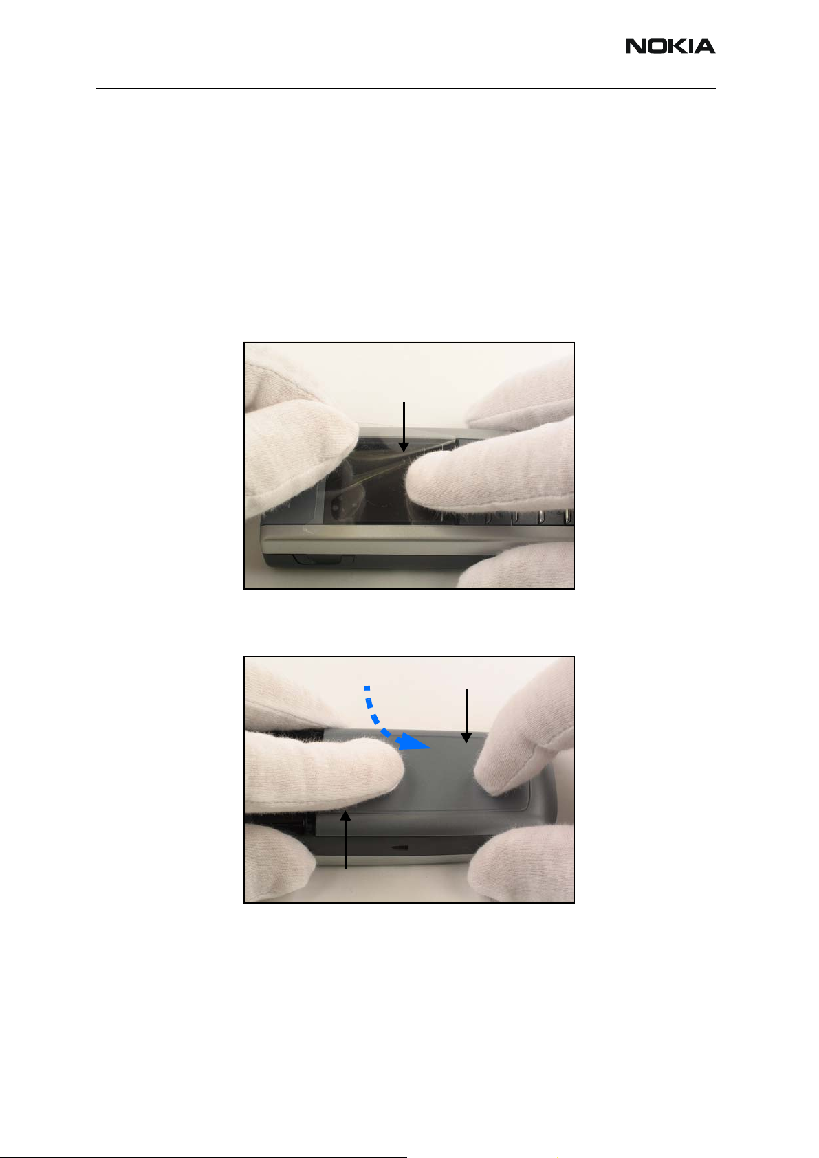
2. Remove the Battery Cover (C-cover)
A. Push down on the release button, and slide the C-cover away from the phone.
Release button
B. Remove the battery.
B-cover
Page 4 ©2005 Nokia Corporation Company Confidential Issue 1 04/2005
Page 5

6235/6235i/6236i (RM-60)
Nokia Customer Care Disassembly/Assembly
3. Remove the A-cover
Rotate A-Cover from the face of phone and remove. Be careful of the header cap and
retaining snaps along either side and at top.
Snaps
A-cover
Notice the keypad does not self-retain within the A-cover and is easily lifted from
position.
4. Place Protective Film
Place protective film on the display (inside) to prevent scratches.
Keypads
Protective Film
Issue 1 04/2005 ©2005 Nokia Corporation Company Confidential Page 5
Page 6

6235/6235i/6236i (RM-60)
Disassembly/Assembly
5. Remove the Screws
A. Use a screwdriver to remove the six Torx screws, in the order shown, to free the UI
module.
LCD Display
1.
2.
B. Place protective film on the LCD display to prevent scratches.
6. Remove the PWB Assembly
Carefully lift the PWB assembly off the B-cover. Be sure not to damage the camera and
battery connectors.
3.
4.
5.
6.
Page 6 ©2005 Nokia Corporation Company Confidential Issue 1 04/2005
Page 7

6235/6235i/6236i (RM-60)
Nokia Customer Care Disassembly/Assembly
7. Separate the LCD Display from the PWB
Gently lift the LCD display off of the PWB. Be careful of the attachment point, since it is
the only fixed mounting point for this assembly once the six Torx screws have been
removed.
Hint: Use a pair of tweezers to gently pry this interface apart.
8. Remove the Earpiece
Use the locating tab to gently lift to remove the speaker from its mount. Be careful not
to touch the spring contacts.
Locating Tab
Issue 1 04/2005 ©2005 Nokia Corporation Company Confidential Page 7
Page 8

6235/6235i/6236i (RM-60)
Disassembly/Assembly
9. LCD Display Disassembly
A. Open the snaps (highlighted below) on both sides of the LCD frame using an
appropriate tool.
B. Gently remove frame, taking care not to damage it.
C. Gently pry the LCD shield mounting tabs to remove the shield fro the LCD frame.
10. Remove the Camera from PWB
A. Always use Camera Removal Tool to release Camera Module. Press the tabbed end into
Camera Module and release the four mounting tabs on both the top and bottom.
B. Use opposite end of tool to lift camera from its mount. Be careful not to damage any
contacts.
Note: Remember to use the orientation tab on camera housings.
Page 8 ©2005 Nokia Corporation Company Confidential Issue 1 04/2005
Page 9

6235/6235i/6236i (RM-60)
Nokia Customer Care Disassembly/Assembly
11. Remov e t h e Volum e Key
A. Applying gentle pressure, push the volume key backwards, and then lift upwards to
remove from the B-Cover.
Snaps
Note: The snaps on either side must clear the retainers.
12. Remove the Vibra, Microphone, and DC Jack
Use a tweezers to carefully remove the vibra (A), microphone (B), and DC jack (C) from
the B-cover.
A
C
Battery cover
latch spring arm
Note: Be aware of the battery cover latch spring arm. It might fall out, due to its
placement underneath the microphone assembly.
B
Issue 1 04/2005 ©2005 Nokia Corporation Company Confidential Page 9
Page 10

6235/6235i/6236i (RM-60)
Disassembly/Assembly
13. Remove the UHJ Sliding Cover
Note the sliding UHJ cover and the relative slot/tab arrangement prior to disassembly.
Slide cover so that the tab lines up with the opening slot, and then use tweezers to
gently pull it away from the B-Cover.
14. Remove the Power Key
Using tweezers, gently pinch the power key by the top-right Torx screw hole and lift
upwards to remove it from its mount.
Note: The other end of the power key will separate from the IR lens.
Page 10 ©2005 Nokia Corporation Company Confidential Issue 1 04/2005
Page 11

6235/6235i/6236i (RM-60)
Nokia Customer Care Disassembly/Assembly
15. Remove the Infrared Lens
After the power key is removed, use tweezers to gently lift the infrared lens from its
mount
16. Remove the Antenna/IHF Speaker
Using tweezers, gently pry the antenna/IHF speaker assembly from the C-Cover at the
sides, top, and bottom. Once loose, you can easily pick the assembly from the hole, at the
top right, between the antenna pins.
Antenna pins
Issue 1 04/2005 ©2005 Nokia Corporation Company Confidential Page 11
Page 12

6235/6235i/6236i (RM-60)
Disassembly/Assembly
17. Remove the SIM Cover
A. Grab the C-Cover so that you can open the SIM cover.
B. Rotate the cover to reveal the inside (vs. the outside back). Gently unsnap the cover
from its mounts and remove.
Page 12 ©2005 Nokia Corporation Company Confidential Issue 1 04/2005
 Loading...