

Page 1

CCS Technical Documentation
RH-12/RH-28 Series Transceivers
6(b) - RF Troubleshooting
Instructions
Issue 1 02/04 Nokia Corporation
Page 2
RH-12/RH-28
RF Troubleshooting Instructions CCS Technical Documentation
[This page left intentionally blank]
Page 2 Nokia Corporation Issue 1 02/04
Page 3

RH-12/RH-28
CCS Technical Documentation RF Troubleshooting Instructions
Table of Contents
Page No
Introduction.................................................................................................................... 5
Notes on reference measurements ...............................................................................5
Helgo / Synthesizer Troubleshooting............................................................................. 6
N500 Helgo troubleshooting ........................................................................................7
Synthesizer troubleshooting .........................................................................................8
Tx Troubleshooting........................................................................................................ 9
Tx 850/900 GMSK troubleshooting ..........................................................................10
Tx 1800/1900 GMSK troubleshooting ......................................................................11
Rx Troubleshooting...................................................................................................... 12
Rx 850/900 troubleshooting ......................................................................................13
Rx 1800 troubleshooting ............................................................................................14
Rx 1900 troubleshooting ............................................................................................15
Bluetooth / FM Radio Troubleshooting ....................................................................... 16
Bluetooth troubleshooting .........................................................................................17
FM radio troubleshooting ..........................................................................................18
Issue 1 02/04 Nokia Corporation Page 3
Page 4

RH-12/RH-28
RF Troubleshooting Instructions CCS Technical Documentation
[This page left intentionally blank]
Page 4 Nokia Corporation Issue 1 02/04
Page 5

RH-12/RH-28
CCS Technical Documentation RF Troubleshooting Instructions
Introduction
This document is the troubleshooting guide for RH-12/RH-28. On the following pages
you will find a step-by-step fault finding procedure and reference measurements at the
relevant signal points.
Notes on reference measurements
• LF & DC signals are measured with Textronix 100 MHz Scope
(TDS3014) and P3010 13pF probe.
• RF signals are measured with R&S FSIQ 7GHz Spectrum Analyzer and
Agilent resistive divider probe (10dB, 500ohm).
• Please be aware that the RF connector on service adaptor is leaking
power (into air) and acts as noise source when probing on RX chain. In
1800 band the problem is most severe while there is no external LNA to
amplify the signal above the noise level like in the 1900 band. In 900/
850 band the leakage is not as high due to lower frequency.
• GSM SA settings: RBW=500kHz, VBW=500kHz.
• Bluetooth SA settings: RBW=2MHz, VBW=2MHz.
• All reference measurements were made on a RH-12 phone (GSM900).
RH-28 (GSM850) results should be very similar.
• RF loss Module Repair Jig: 0.3dB (low bands), 0.4dB (high bands).
• RF loss RF Adaptor: 0.4dB (low band), 0.7dB (high bands).
Issue 1 02/04 Nokia Corporation Page 5
Page 6
RH-12/RH-28
RF Troubleshooting Instructions CCS Technical Documentation
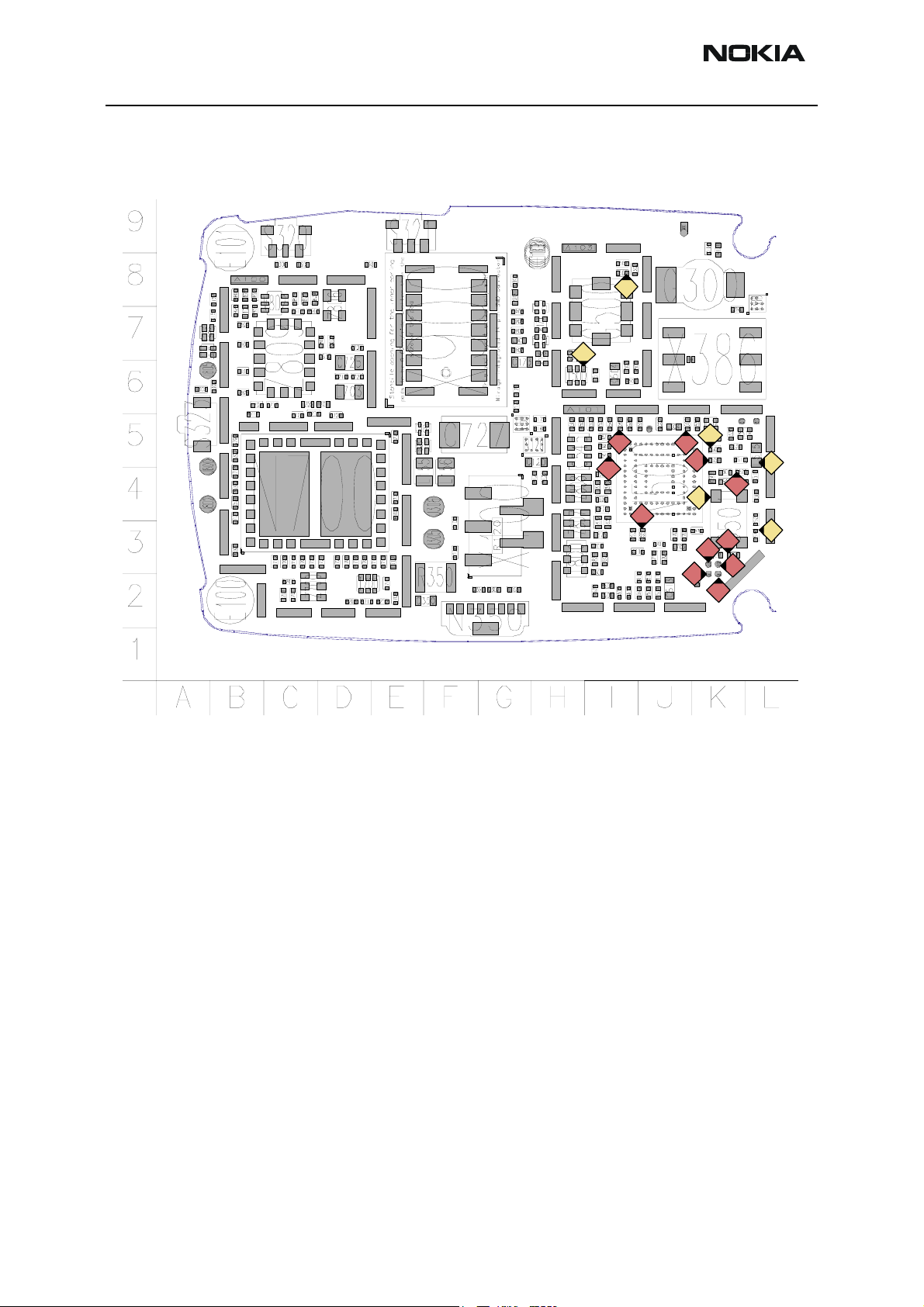
Helgo / Synthesizer Troubleshooting
4b
4a
1f
2
1d
4c
1e
1a
1
1c
3d
3b
3a
3c
2
1b
3
Page 6 Nokia Corporation Issue 1 02/04
Page 7

RH-12/RH-28
CCS Technical Documentation RF Troubleshooting Instructions
N500 Helgo troubleshooting
N500 HELGO troubleshooting
Set Phoenix to RF local burst RX mode
Measure N500 Helgo supply voltages:
- VR1 at C551 - 4,75V?
- VR2 at C520 - 2,8V?
- VR3 at C503 - 2,8V?
- VR4 at C554 - 2,8V?
- VR5 at C553 - 2,8V?
- VR6 at C555 - 2,8V?
- VR7 at C297 - 2,8V? (located at BB bottom grid S3)
Measure N500 reference voltage:
VrefRF01 = 1,35V (C549)
Measure N500 serial bus signals
- RfBusClk at J501
- RfBusEna1 at J502
- Reset at J503
- RfBusData at J509
All measured in Burst Mode
.
Logic high level = 1,8V.
NOK
Check baseband.
Issue 1 02/04 Nokia Corporation Page 7
Page 8

RH-12/RH-28
RF Troubleshooting Instructions CCS Technical Documentation
Synthesizer troubleshooting
Synthesizer Troubleshooting
Phoenix: RF local mode Rx continuous
Frequency = 3590.4 MHz @ ch. 38
Measure G501 VCTCXO output voltage at G501 pin 3
26 MHz 600 mVpp. OK ?
Measure N500 26 MHz reference output voltage at
L515 800 mVpp. OK?
Measure G501 VCTCXO AFC voltage at C540.
Measure RF frequency and level at T500.
Place the probe through the hole in the shield!
Correct frequency found?
NO
No frequency or wrong frequency ?
No frequency found within the 3-4 GHz span
YES
Measure VCO supply voltage at C560
= 2.8 V OK ?
YES
YES
Wrong frequencies found
Measure VCO control voltage at C505.
Voltage = 4.8V?
VCO does not work or
the control loop is open
Synthesizer is ok
YES
NO
Replace VCO
Check C503, R501, R502,
C504, C505
Page 8 Nokia Corporation Issue 1 02/04
Page 9

RH-12/RH-28
CCS Technical Documentation RF Troubleshooting Instructions
Tx Troubleshooting
11a
11a
11b
11b
11c
11c
10
10
6
6
9
9
1b
1a
1b
1a
2a
2a
2b
2b
3
8b
8a
5
8a
5
4
7
7
8b
3
4
Issue 1 02/04 Nokia Corporation Page 9
Page 10

RH-12/RH-28
RF Troubleshooting Instructions CCS Technical Documentation
Tx 850/900 GMSK troubleshooting
TX850/900 GMSK troubleshooting
Apply a 50 ohm load at the antenna connector of the jig.
GSM850/ ch. 190 = 836.6 MHz, burst mode power level 10.
GSM900/ cha. 37 = 897.4 MHz, burst mode power level 10
Spectrum analyzer: RBW = 500 Khz and VBV = 500 kHz,
center = 500 kHz and span = 20 MHz
Measure voltage of a) TXI at C535 and TXQ at C536,
Txi and TXQ = 500 mVpp min. and 1.2 VDC during burst
Measure a) TXC = 950 mV during burst at R522 and
b) TXP = 1.8 V during burst at J504 .
Note: TXC voltage is a function of power level
Measure modulator supply voltage VR2 = 2.7 V (C568, both terminals)
Measure RF level = -13 dBm at input of Z700 SAW filter L700
Measure RF level = -13 dBm at N700 PA input (C707)
Measure RF level = +7 dBm at N700 PA output TX_OUT_EGSM
(Z809)
Measure N700 PA power detector DET = 850 mV during burst at R503.
Note: DET voltage is a function of power level
Measure N700 PA control voltage a) VPCTRL_G = 1.2 V during burst at
R715 and N700 PA bias voltage.
b) VTXB_G = 2.7V (C533).
Note: VPCTRL_G voltage is a function of power level.
NOK
NOK
NOK
NOK
OK
Check
baseband.
Check
N500 Helgo.
Check Z700
Tx SAW.
Measure N700 PA supply voltage VBAT at C724
Measure RF level = 2 dBm at antenna pad J800
Measure Z809 antenna switch control signal voltages
a) VANT_1 = 0 V at C804
b) VANT_2 = 0 V at C806
c) VANT_3 = 2.7 V at C805
Page 10 Nokia Corporation Issue 1 02/04
Page 11

RH-12/RH-28
CCS Technical Documentation RF Troubleshooting Instructions
Tx 1800/1900 GMSK troubleshooting
TX1800/1900 GMSK troubleshooting
Apply a 50 ohm load at the antenna connector of the jig.
GSM1800 ch. 700 = 1747,8 MHz, burst mode power level 5
GSM1900 ch. 661 = 1880,0 MHz, burst mode power level 5
Spectrum analyzer RBW = 500 kHz and VBW = 500 kHz,
center = 500 kHz and span = 20 MHz
Measure voltage of a) TXI at C535 and TXQ at C536,
Txi and TXQ = 500 mVpp min. and 1.2 VDC during burst
Measure a) TXC = 900 mV during burst at R522 and
b) TXP = 1.8 V during burst at J504 .
Note: TXC voltage is a function of power level
Measure modulator supply voltage VR2 = 2.7 V at R539
Measure RF level = -15 dBm at input of T700 Tx balun C709
Measure RF level = -20 dBm at N700 PA input L702
Measure RF level = -3 dBm at N700 PA output TX_OUT_DCS (Z809)
NOK
Measure N700 PA power detector DET = 810 mV during burst at R503.
Note: DET voltage is a function of power level
Measure N700 PA control voltage a) VPCTRL_P = 1.0 V during burst at R716
and N700 PA bias voltage
b) VTXB_P = 2.7 V (C532).
Note: VPCTRL_P voltage is a function of power level.
NOK
NOK
NOK
OK
Check
baseband.
Check
N500 Helgo.
Check T700
Tx balun.
Measure N700 PA supply voltage VBAT at C724
Measure RF level = 2 dBm at antenna pad J800
Measure Z809 antenna switch control signal voltages
a) VANT_1 = 2.7 V at C804
b) VANT_2 = 2.7 V at C806
c) VANT_3 = 0 V at C805
Issue 1 02/04 Nokia Corporation Page 11
Page 12

RH-12/RH-28
RF Troubleshooting Instructions CCS Technical Documentation
Rx Troubleshooting
6b
5
3a
3a
3c
3c
3c
3b
3b
4
6a
2
2
3a
2
3b
1a
1a
1a
4
4
4
1b
1b
1b
Page 12 Nokia Corporation Issue 1 02/04
Page 13

RH-12/RH-28
CCS Technical Documentation RF Troubleshooting Instructions
Rx 850/900 troubleshooting
RX 850/900 Troubleshooting
GSM850 ch. 190 or GSM900 ch. 37. Continuous Rx.
Use AGC “gain step” 14
Apply a signal of 942.46771 MHz (+67.71 kHz offset)
at -90 dBm to the antenna pad J800
Spectrum analyzer: RBW = 500 kHz, VBW = 500 kHz,
center = 942 MHz and span = 20 MHz
Measure voltage of a) RXI (J511) b) RXQ (J510). RXI and
RXQ = 800 mVpp and 1.35 VDC.
Note: DC level drops after a while.
Change the signal level to -30 dBm
OK
Measure RF level = -55 dBm at Z808 SAW filter input.
NOK
Measure Z809 antenna switch control signal voltages
a) VANT_1 = 0V (C804)
b) VANT_2 = 0V (C806)
c) VANT_3 = 0V (C805).
OK
Measure RF level = -55 dBm
at Helgo input (C840, both terminals).
NOK
go to
“Helgo/Synthesizer
troubleshooting”
OK
Issue 1 02/04 Nokia Corporation Page 13
Page 14

RH-12/RH-28
RF Troubleshooting Instructions CCS Technical Documentation
Rx 1800 troubleshooting
RX 1800 Troubleshooting
GSM1800 ch. 700. Continuous Rx.
Use AGC “gain step” 14
Apply a signal of 1842,86771 MHz (+67.71 kHz offset)
at -90 dBm to the antenna pad J800
Spectrum analyzer: RBW = 500 kHz, VBW = 500 kHz,
center = 1840 MHz and span = 20 MHz
Measure voltage of a) RXI (J511) b) RXQ (J510).
RXI and RXQ = 500 mVpp and 1.35 VDC.
Note: DC level drops after a while.
Change the signal level to -30 dBm
OK
Measure RF level = -30 dBm at Z807 SAW filter input.
(Z809 antenna switch pin X)
NOK
Measure Z809 antenna switch control signal voltages
a) VANT_1 = 0V (C804)
b) VANT_2 = 0V (C806)
c) VANT_3 = 0V (C805).
OK
Measure RF level
(C839, not assembled, both terminals).
at Helgo input
NOK
go to
“Helgo/Synthesizer
troubleshooting”
OK
Page 14 Nokia Corporation Issue 1 02/04
Page 15

RH-12/RH-28
CCS Technical Documentation RF Troubleshooting Instructions
Rx 1900 troubleshooting
RX 1900 Troubleshooting
GSM1900 ch. 661. Continuous Rx.
Use AGC “gain step” 12.
Apply a signal of 1960,06771 MHz (+67.71 kHz offset)
at -90 dBm to the antenna pad J800.
Spectrum analyzer: RBW = 500 kHz, VBW = 500 kHz,
f = 1960 MHz and span = 20 MHz
Measure voltage of a) RXI (J511) b) RXQ (J510). RXI and
RXQ = 700 mVpp and 1.35 VDC.
Change the signal level to -50 dBm and set “gain step” = 6
OK
Measure RF level at Z806 SAW filter input.
(Z809 antenna switch pin X)
NOK
Measure antenna switch control signal voltages
a) VANT_1 = 0V (C804)
b) VANT_2 = 2.7V (C806)
c) VANT_3 = 0V (C805).
Measure RF level at V802 LNA input (C826).
Measure RF level at V802 LNA output (C829)
Measure a) V802 LNA supply voltage LNA_P = 2.8 V (V802 pin 4)
and b) LNA control voltage LNAB_P = 2,8 V (R801)
go to
“Helgo/Synthesizer
troubleshooting”
Measure RF level at N500 Helgo input (L805).
OK
Issue 1 02/04 Nokia Corporation Page 15
Page 16

RH-12/RH-28
RF Troubleshooting Instructions CCS Technical Documentation
Bluetooth / FM Radio Troubleshooting
4c
8
9
5
7a
4a
6a
6b
7b
1
2
2d
3
4b
2c
2b
4
5
2e
2a
3
1b
1a
l
na
s
g
-
M
F
i
Page 16 Nokia Corporation Issue 1 02/04
Page 17

RH-12/RH-28
CCS Technical Documentation RF Troubleshooting Instructions
Bluetooth troubleshooting
Bluetooth troubleshooting
Phoenix local mode: Tx data 1 ch. 39 (2441 MHz approx. 1 MHz BW).
BC02 Bluetooth control. Options: Internal gain = 52
Spectrum analyzer: RBW = 500 kHz, VBW = 500 kHz,
center = 942 Mhz and span = 20 Mhz.
Measure PURX voltage = 1.8 V (N131)
OK
Measure N130 BT supply voltage = 2.8V (C144).
OK
Measure N130 VDD-ANA voltage regulator output = 1.8V (C140).
OK
Measure a) N130 VDD_VCO supply voltage = 1.8V (C137)
b) VDD_MEM supply voltage = 1.8V
c) Rx/Tx supply voltage = 1.8V (C130)
OK
Measure SYSCLK voltage = 550 mVpp (26 MHz) 1.3 VDC (C133).
OK
Measure N130 XTAL_IN
voltage = 1.8Vpp square wave (R131)
OK
NOK
NOK
NOK
Measure D130 supply voltage = 2,8V
at D130 pin 5
Check L131, L132. If passive componentsOK, replace D130.
BB troubleshooting
Replace N131
NOK
NOK
NOK
Replace N130
Check L133, R132
and L130
Check C133 and go to
Synthesizer
troubleshooting.
NOK
Measure RF level = -15 dBm at a TX_A (C131)
and b) TX_B (C132).
OK
Measure RF level = -18 dBm at Z131 SAW filter input.
OK
Measure RF level = -18 dBm at Z131 SAW filter output.
NOK
Check L131, L132. If passive components
OK, replace N130
NOK
NOK
Check T130 and C130
Replace Z131
Issue 1 02/04 Nokia Corporation Page 17
Page 18

RH-12/RH-28
RF Troubleshooting Instructions CCS Technical Documentation
FM radio troubleshooting
FM Radio Troubleshooting
Phoenix: Testing -> FM radio -> Power on.
FM signal: Frequency = 100 MHz, frequency deviation = 67.5 kHz, modulation fre-
quency = 1 kHz, R=L, pilot tone on and RF level -67 dBm. Signal is injected at X102
bottom connector pin 11, 12, 13 or 14.
Alternative: Use FM signal received by headset.
Measure audio voltage a) VAFL = 200 mVpp
(1 kHz) 850 mVDC (C380, both sides
b) VAFR = 200mVpp (1 kHz) 850 mVDC
(C382, both sides).
NOK
Measure N356 supply voltages a) VCCD = 2.78 V (C359)
b) VCCA = 2.78 V (C372)
c) VCCVCO = 2.78 V (C362)
d)VCOTANK1 = 2.78 V (L356)
e) VCOTANK2 = 2.78 V (L357).
OK
Measure N356 XTAL2 voltage = 600 mVpp
(32.768 kHz) 1.7 VDC (C375)
OK
Measure CPOUT voltage = 0.9 V @ 100 MHz (V356).
OK
NOK
OK
NOK
FM Radio OK
NOK
Check V356, V357, L356,
L357, R359,
C357 and C358.
Check passives
and then go to
BB troubleshooting.
Check C374 and C375,
then go to
BB troubleshooting
NOK
Measure RF level at antenna input (C367).
Visual inspect C110-C113, L103 (all bottom
side, grid T5), C367, C378, C379 and L358.
Page 18 Nokia Corporation Issue 1 02/04
 Loading...