

Page 1

Nokia Customer Care
RH-27 Series Transceivers
Disassembly and Reassembly
Issue 2 12/2004 Confidential ©2004 Nokia Corporation
Page 2

RH-27
Disassembly and Reassembly Nokia Customer Care
Contents
Page No
Disassembly Instructions ............................................................................................... 3
Reassembly .................................................................................................................... 8
Page 2 ©2004 Nokia Corporation Confidential Issue 2 12/2004
Page 3
RH-27
Nokia Customer Care Disassembly and Reassembly
Disassembly Instructions
(Also see video clips on care point.)
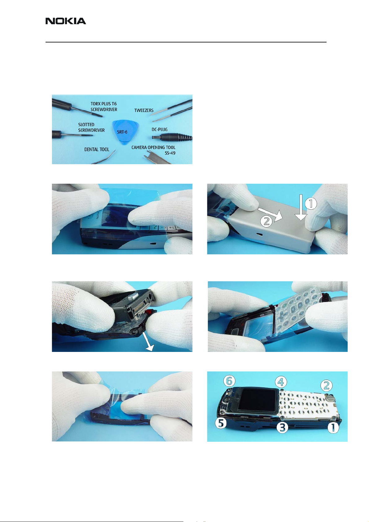
1) Needed tools for disassembly/assembly.
2) Check the condition of the window and protect the window with a film.
4) Remove the A-Cover. 5) Take away the Keymat.
3) Press the Release Button before pulling up the B-Cover.
6) Protect the inner side of the window with a film. 7) Unscrew the six Torx PLUSÆ size 6 screws. For assembly,
the reverse order and a torque driver with a torque of
20Ncm have to be used.
Issue 2 12/2004 Confidential ©2004 Nokia Corporation Page 3
Page 4

RH-27
Disassembly and Reassembly Nokia Customer Care
8) Remove the modules from the C-Cover. 9) Open the snaps with SRT-6 on both sides of the Engine
Module.
10) Unplug the display connector by pulling the modules
apart carefully.
12) Unlock the clips with SRT-6 on both sides of the Display
Shield.
11) Remove the BB Shield.
13) Remove the Display Shield.
14) Protect LCD Module with a film. 15) Remove the LCD Module by using SRT-6 as shown in the
picture.
Page 4 ©2004 Nokia Corporation Confidential Issue 2 12/2004
Page 5

RH-27
Nokia Customer Care Disassembly and Reassembly
16) The Earpiece is attached with double-sided adhesive
Foam Tape.
18) Do not damage the spring contacts, when removing the
Microphone.
17) Unlock UI Module on the left side first and lift it up carefully.
19) Spread the B-Cover from both sides until snaps inside
will release it.
20) Remove the B-Cover carefully. 21) A DC plug can be used to remove the DC Jack.
22) Remove the Vibra Motor with tweezers. 23) Remove the Release Spring.
Issue 2 12/2004 Confidential ©2004 Nokia Corporation Page 5
Page 6

RH-27
Disassembly and Reassembly Nokia Customer Care
24) The Release Key can be removed by pushing with tweez-
ers through the opening in C-Cover.
26) Remove the Power Key. 27) Remove the Volume Key.
Camera removal
25) Remove the Headset Jack.
28) A slotted screwdriver can be used as a lever to open the
Camera Shield.
30) Unlock the snaps as shown in the picture. Note! The
Camera removal tool has two different endings. For
removal, use the side with four pikes.
29) The Camera Module is attached with six snaps into its
guidance. Place SS-49 as shown in the picture. Note the
release order.
31) Turn over the removal tool and unlock the other snaps.
Page 6 ©2004 Nokia Corporation Confidential Issue 2 12/2004
Page 7

RH-27
Nokia Customer Care Disassembly and Reassembly
32) Remove the Camera Module carefully. Take care that the
camera marking is directed to the right side when assembling. Do not touch contacts and camera lens. For disassembly, use SS-42 or tweezers if the tool is not available.
Issue 2 12/2004 Confidential ©2004 Nokia Corporation Page 7
Page 8

RH-27
Disassembly and Reassembly Nokia Customer Care
Reassembly
Reassembly should be in reverse order to disassembly unless otherwise stated.
Page 8 ©2004 Nokia Corporation Confidential Issue 2 12/2004
 Loading...