

Page 1

CCS Technical Documentation
RH-27 Series Transceivers
Troubleshooting - Antennas
Issue 1 11/2003 Confidential ©2003 Nokia Corporation
Page 2

RH-27
Troubleshooting - Antennas CCS Technical Documentation
Contents
Page No
Troubleshooting - Antennas........................................................................................... 3
Failures and Corrective Measures ...............................................................................3
Appearance of phone................................................................................................. 3
Missing internal antenna or antenna radiator............................................................ 3
Missing GPS antenna, damaged GPS feed/ground pin or damaged heatstick.......... 4
RF feed pin/ground pin, IHF speaker pins in C-cover missing or damaged............. 5
Obstructed RF feed & ground pads, GPS feed and ground pads, IHF speaker pads 6
CDMA or GPS RF connector failure........................................................................ 6
Display Assembly ..................................................................................................... 7
Missing or damaged baseband shield........................................................................ 9
Page 2 ©2003 Nokia Corporation Confidential Issue 1 11/2003
Page 3
RH-27
CCS Technical Documentation Troubleshooting - Antennas
Troubleshooting - Antennas
This troubleshooting guide addresses potential failures that will affect the antenna performance of the RH-27 phone, and discusses methods for correction of these failures.
Failures and Corrective Measures
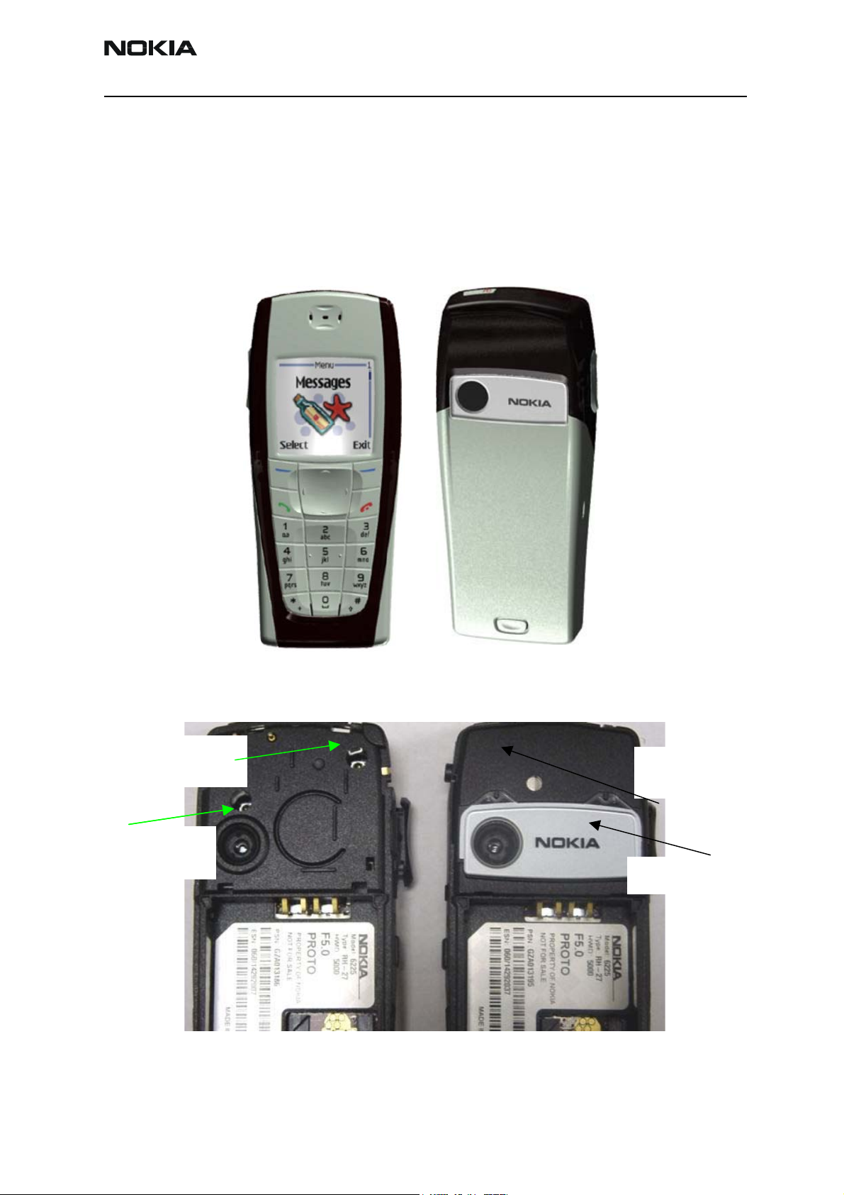
Appearance of phone
Figure 1: Front and back views of the RH-27 (6225) phone
Missing internal antenna or antenna radiator
Internal
antenna
Antenna cap
is missing
Figure 2: RH-27 (6225) phone with and without antenna cap
Antenna
Slot
Antenna cap
Issue 1 11/2003 Confidential ©2003 Nokia Corporation Page 3
Page 4

RH-27
r
g
Troubleshooting - Antennas CCS Technical Documentation
Antenna
radiato
Figure 3: RH-27 (6225) antenna cap with and without radiator
If the antenna cap is missing or there is a cap but it has no radiator, install a new
antenna cap with radiator. If the radiator looks obviously damaged (dents, corrosion) or
the slot in the radiator has a significantly different shape, then install a new antenna cap
with correct radiator.
If no antenna or no radiator is installed, the antenna gain will be degraded by more than
25 dB.
Missing GPS antenna, damaged GPS feed/ground pin or damaged heatstick
GPS antenna
Heat stake of
GPS antenna
Figure 4: Back view of RH-27 (6225) C-cover with GPS antenna assembled
RH-27 GPS antenna is heat-staked to the C-cover. If any of the following events occurs,
the entire C-cover assembly should be replaced with a new one:
1 GPS antenna is missing
2 GPS antenna looks obviously damaged
GPS
round pin
GPS
feed pin
3 Any of the three heat stakes appears damaged; the GPS antenna will be loose
4 Any of the three heat stakes are over-heated and GPS antenna melts into the
C-cover; antenna will look distorted and bent
5 Either GPS antenna feed or ground leg is broken or bent so that either pin will
not touch the PWB.
Page 4 ©2003 Nokia Corporation Confidential Issue 1 11/2003
Page 5

RH-27
pogo p
pogo pin
pogo p
CCS Technical Documentation Troubleshooting - Antennas
RF feed pin/ground pin, IHF speaker pins in C-cover missing or damaged
GPS antenna
IHF speaker
ins
RF ground
in
RF feed
Figure 5: Inside view of the C-cover
Two pogo pins are inserted in the C-cover. One end of the pogo pin touches the antenna,
the other end (in Figure 5) touches the pad on the PWB. If either of the pogo pins is
missing, or either of the pogo pins is obviously damaged (stuck in the C-cover plastic
tube, loose the inside spring force), the antenna will lose the contact to the PWB.
Replace the whole C-cover assembly with a correct new one.
If the RF feed doesn't touch the PWB, then the antenna gain will degrade by more than
25 dB. If the ground pin doesn't touch the PWB, then the antenna gain may degrade
about 5 to 10 dB.
If either of the IHF speaker pins is damaged or missing, the speaker will not connect to
PWB. Antenna PCS gain will drop 2 dB. The C-cover assembly should be replaced.
Issue 1 11/2003 Confidential ©2003 Nokia Corporation Page 5
Page 6

RH-27
p
p
p
g
pad
Troubleshooting - Antennas CCS Technical Documentation
Obstructed RF feed and ground pads, GPS feed and ground pads, IHF speaker pads
GPS Feed
ad
GPS ground
ad
IHF speaker
ads
GPS RF
connector
Internal
round pad
Internal
Feed
CDMA RF
connector
Figure 6: PWB layout of RF feed/ground pads, GPS feed/ground pads, and IHF speaker pads
If the RF feed pad is obstructed, removed, or covered, then the internal antenna feed
pogo pin will not touch the PWB and the antenna gain will degrade by more than 25 dB.
If the ground pad is obstructed, removed, or covered, then the ground pogo pin will not
touch the PWB and the antenna gain will degrade by more than 5 dB. If corrosion is
present or the pad is missing, then the PWB and phone most likely needs to be replaced.
If either pad is obstructed or covered, the pad should be cleared and/or cleaned.
If the GPS feed pad is obstructed, removed, or covered, then the GPS antenna feed leg
will not touch the PWB. If the ground pad is obstructed, removed, or covered, then the
ground spring clip will not touch the PWB.
If the Internal Hands Free (IHF) speaker pads are obstructed, removed, or covered, then
the IHF speaker will not produce sound. The antenna PCS gain will be degraded by about
2 dB. If corrosion is present or the pad is missing, then the PWB and phone most likely
needs to be replaced. If either pad is obstructed or covered, the pad should be cleared
and/or cleaned.
CDMA or GPS RF connector failure
CDMA and GPS use the same type of RF connector. The RF connector could fail by not
connecting the RF input to the RF output of the RF connector. If this happens to the
CDMA RF connector, then the antenna gain will degrade by about 25 dB. If this happens
to the GPS RF connector, the GPS antenna gain will degrade by about 20 dB. This can be
checked by testing for DC conductivity between the RF input and RF output of the RF
connector. Note the DC conductivity test must be done without any cable attached to
the RF connector. Since the RF connector is also a switch, the RF output will be disconnected from the RF input when a cable is inserted into the RF connector. When a cable is
not inserted, the RF input is connected to the RF connector. The locations of both RF
Page 6 ©2003 Nokia Corporation Confidential Issue 1 11/2003
Page 7

RH-27
p
d
CCS Technical Documentation Troubleshooting - Antennas
connectors are shown in Figure 6.
CDMA RF input — connects to duplexer
CDMA RF output — connects to antenna pad through vias
GPS RF input — connects to GPS ceramic filter output
GPS RF output — connects to GPS antenna matching circuits
RF connector — connects to coaxial cable
If the RF input is not connected properly to the RF output, then the RF connector must
be replaced.
Display Assembly
Grounding of the display shield and frame
Grounded
osition
isplay Frame
lated area
Display
shiel
Display
Frame
Figure 7: RH-27 display assembly (above, right) and side view of RH-27 display assembly (above, left)
The display shield is connected to the display frame plated area (screw boss area) and
then the the PWB through the two top screws. The grounding of the display shield and
frame will impact the radiation performance of the phone. If the screws are loose,
tighten them. If the screw bosses are stripped, the chassis will need to be replaced. If the
screws are missing, install new ones.
Issue 1 11/2003 Confidential ©2003 Nokia Corporation Page 7
Page 8

RH-27
shield
N
Troubleshooting - Antennas CCS Technical Documentation
If the display frame plated area is cracked or the metal plating is peeled off, then the
grounding of the display shield and frame will not be guaranteed. Replace the frame.
Wrong display assembly installed
RH-34
Display
o plating
RH-34 Display
frame plating
Figure 8: Side view of RH-34 and RH-27 display assembly
RH-27
Display
shield
RH-27 Display
frame plating
Figure 9: Back view of RH-34 and RH-27 display assembly
Display assemblies of RH-34 (6585) and RH-27 (6225) are very similar. However, the
RH-27 display shield is different on the side from the RH-34 shield, as shown in Figure 9
inside the blue dashed line. Second, the metal plating at the top area of the RH-27 frame
is different from the top of the RH-34 frame, as shown in Figure 9 inside the blue dashed
line. For RH-34 frame, the screw boss area is plated but isolated from the rest of the
frame, and also there is no plating in the area inside the green dashed line in Figure 9.
Page 8 ©2003 Nokia Corporation Confidential Issue 1 11/2003
Page 9

RH-27
shield
CCS Technical Documentation Troubleshooting - Antennas
For the RH-27 frame, the whole top area is fully plated.
If the wrong display shield or frame is installed, replace it with a correct one.
Missing or damaged baseband shield
without
RH-27
base band
baseband
shield
Figure 10: RH-27 baseband shield assembly
Baseband shield is part of the display assembly. If the baseband shield is missing or is
obviously damaged, the radiated phone performace will be impacted. Check spring fingers on baseband shield to ensure that they are raised up so that when installed, they
make contact with the PWB. If damaged, install a new baseband shield.
Issue 1 11/2003 Confidential ©2003 Nokia Corporation Page 9
Page 10

RH-27
Troubleshooting - Antennas CCS Technical Documentation
Page 10 ©2003 Nokia Corporation Confidential Issue 1 11/2003
 Loading...