

Nokia 620 Service manual

Service Manual for L1 and L2
6
z
z
z
z
z
z
Nokia Lumia 620
RM-84
Key features
Complete WP8 experience
Edge-to-edge 3.8" ClearBlack display
1 GHz dual core processor
8 GB internal mass memory / 512 MB RAM
Cup-shaped body with changeable covers
720p HD video recording
Version 1.0
Exploded view Disassembly steps Assembly hints
Check the repair
policy before
performing any
mechanical repair
on Service Level
1&2!
More More More
Solder components Service devices Product controls and interfaces
More More More
Service concept Phone reset
More More
©2012 Nokia | Nokia Internal Use only | All Rights Reserved.

Service Manual Level 1 and 2
Nokia Lumia 620
RM-846
Version 1.0
WINDOW FRAME ASSEMBLY
(I0001 - I0002)
Exploded view
TOUCH MODULE
EARPIECE HOLDER
ADHESIVE
EARPIECE DUSTNET
EARPIECE
PROXIMITY & ALS SENSOR
2
PWB MODULE
DISPLAY SUPPORT
ASSEMBLY
LIGHT SWAP PACKAGE
(I0010)
LIGHT SWAP PWB
I0001
I0002
I0008
I0009
I0006
I0004
I0010
EARPIECE HOLDER
I0007
DISPLAY
I0003
TYPE LABEL
I0005
CWS CARRIER ASSEMBLY
(I0013)
5
FLASH FLEX MODULE
SCREW TORX+
SIZE 4 RF1.6 x 4.5
v1.0
CAMERA
I0011
I0013
SIM TRAY
I0017
I0015
Only available
as assembly
USB BOOT ASSEMBLY
USB BOOT
I0012
MAIN ANTENNA ASSEMBLY
IHF SPEAKER
I0014
SCREW TORX+
SIZE 4 M1.4 X 3.4
I0016
BACK COVER
I0018
Not reuseable
after removal
(I0012)
(I0014)
Repair/swap
only in level 3
4
6
©2012 Nokia | Nokia Internal Use only | All Rights Reserved.
Service Manual Level 1 and 2
Nokia Lumia 620
RM- 846
Version 1.0
Disassembly steps
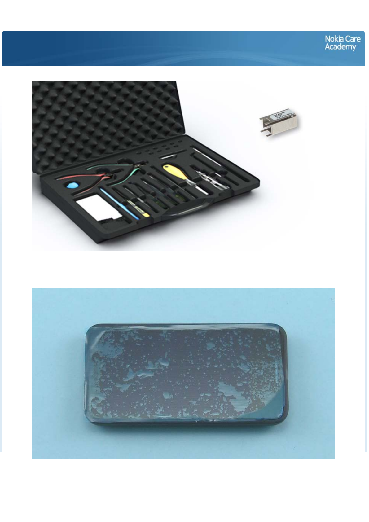
For disassembling you need the Nokia Standard toolkit version 2. You will also need the camera removal
tool SS-296.
Protect the TOUCH MODULE with the protective film.

Release the BACK COVER by pushing the device down from the camera deco.
Lift up and remove the BACK COVER.

Pull out and remove the SIM TRAY.
Unscrew the six Torx+ size 4 screws. Note that the two screws in the middle are different type of screws
than the other four screws! If the screws are scratched, do not use them again.
Lift up and remove the MAIN ANTENNA ASSEMBLY.
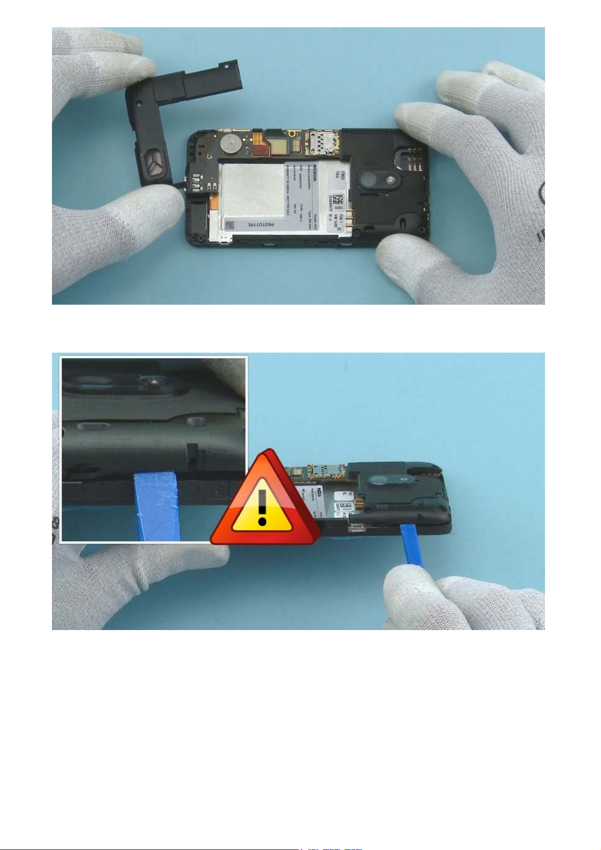
Insert the SS-93 to the shown place and release the side of the CWS CARRIER ASSEMBLY. Be careful not
to damage the spring clips beneath the CWS CARRIER ASSEMBLY.

Insert the SS-93 to the shown place and release also the other side of the CWS CARRIER ASSEMBLY. Be
careful not to damage the spring clips beneath the CWS CARRIER ASSEMBLY.
Lift up and remove the CWS CARRIER ASSEMBLY.
 Loading...