

nokia 503 x
Service Manual for L1 andL
2
M
z
z
z
z
z
n
Nokia Asha 503 Dual SIM
Nokia Asha 503
RM-922, RM-958 (Dual SIM)
R
-920, RM-947, RM-959 (Single SIM)
Key features
5 MP Camera with a LED flash
3.0 QVGA Curved Gorilla glass display
Capacitive touch screen
Capacitive Back key
Wi-fi support
Versio
1.0
Check the repair
policy before
performing any
mechanical
repair on Service
Level 1&2!
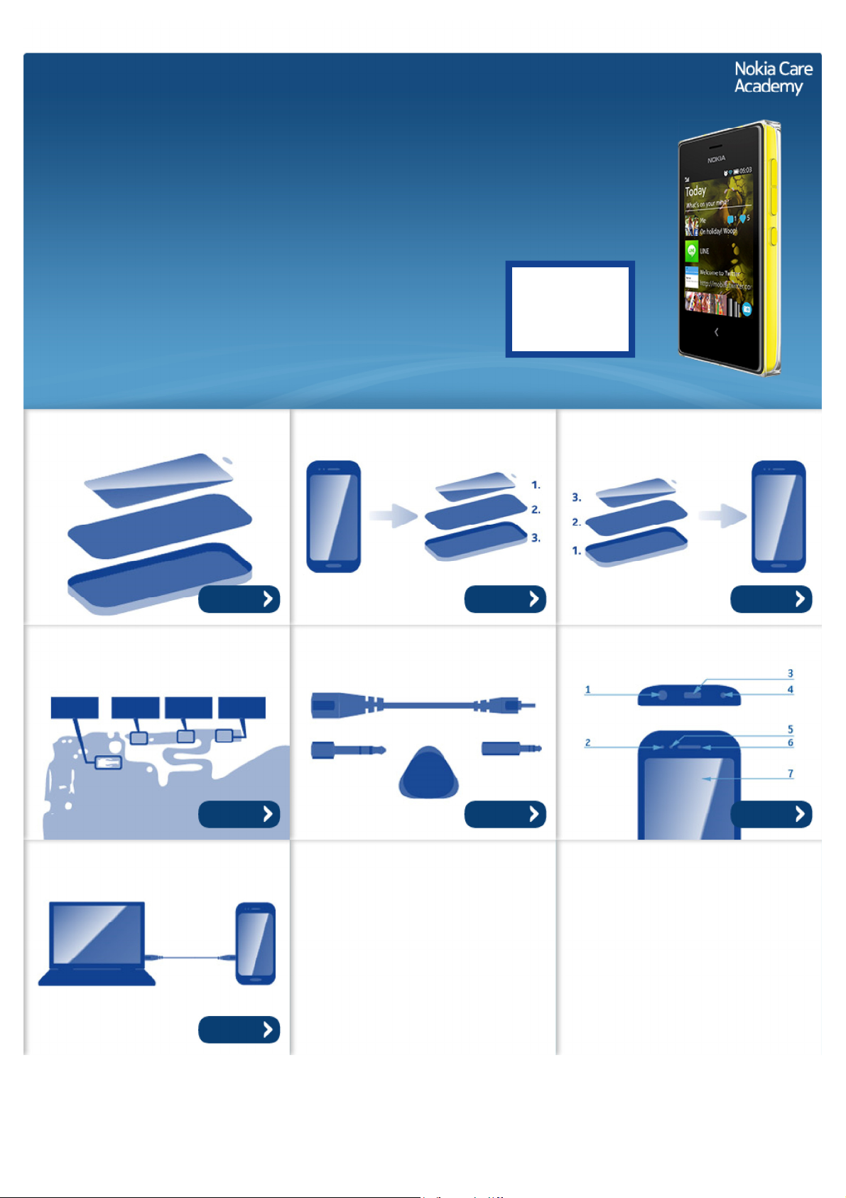
Exploded view Disassembly steps Assembly hints
More More More
Solder components Service devices Product controls and interfaces
Service concept
More More More
More
©2013 Nokia | Nokia Internal Use only | All Rights Reserved.
Service Manual Level 1 and 2
Nokia Asha 503 Dual SIM, Nokia Asha 503
RM-922 RM-958 (DS), RM-920 RM-947 RM-959 (SS)
Version 1.0
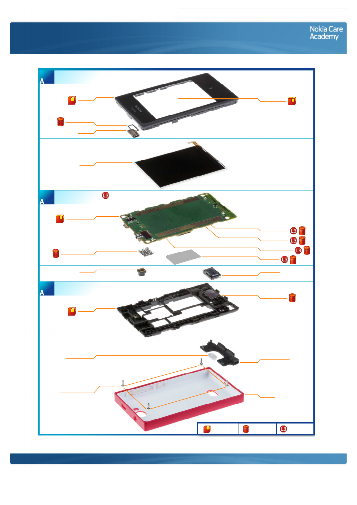
A-COVER ASSEMBLY WITH TOUCH WINDOW
(I0001 - I0004)
1
Exploded view
EARPIECE GASKET
LIGHT SWAP PACKAGE
(I0006 - I0011)
2
LIGHT SWAP PWB
WLAN SHIELDING LID
A-COVER
I0001
I0004
EARPIECE
I0003
DISPLAY
I0005
I0006
I0010
CAMERA
I0012
TOUCH MODULE
I0002
RF SHIELDING LID
I0008
BB SHIELDING LID
I0007
BT FM SHIELDING LID
I0009
TYPE LABEL
I0011
IHF SPEAKER
I0016
D-COVER ASSEMBLY
(I0013 - I0014)
3
RELEASE BUTTON
SCREW TORX+ SIZE 6
D-COVER
I0013
I0017
M1.6 x 5.0
I0018
Only available
as assembly
©2013 Nokia | Nokia Internal Use only | All Rights Reserved.
SPEAKER GASKET
I0014
ANTENNA MODULE
I0015
B-COVER
I0019
Not reuseable
after removal
Repair/swap
only in level 3
Service Manual Level 1 and 2
Nokia Asha 503 Dual SIM, Nokia Asha 503
RM- 922 RM -958 (DS), RM- 920 RM-947 RM-959 (SS)
Version 1.0
Disassembly steps
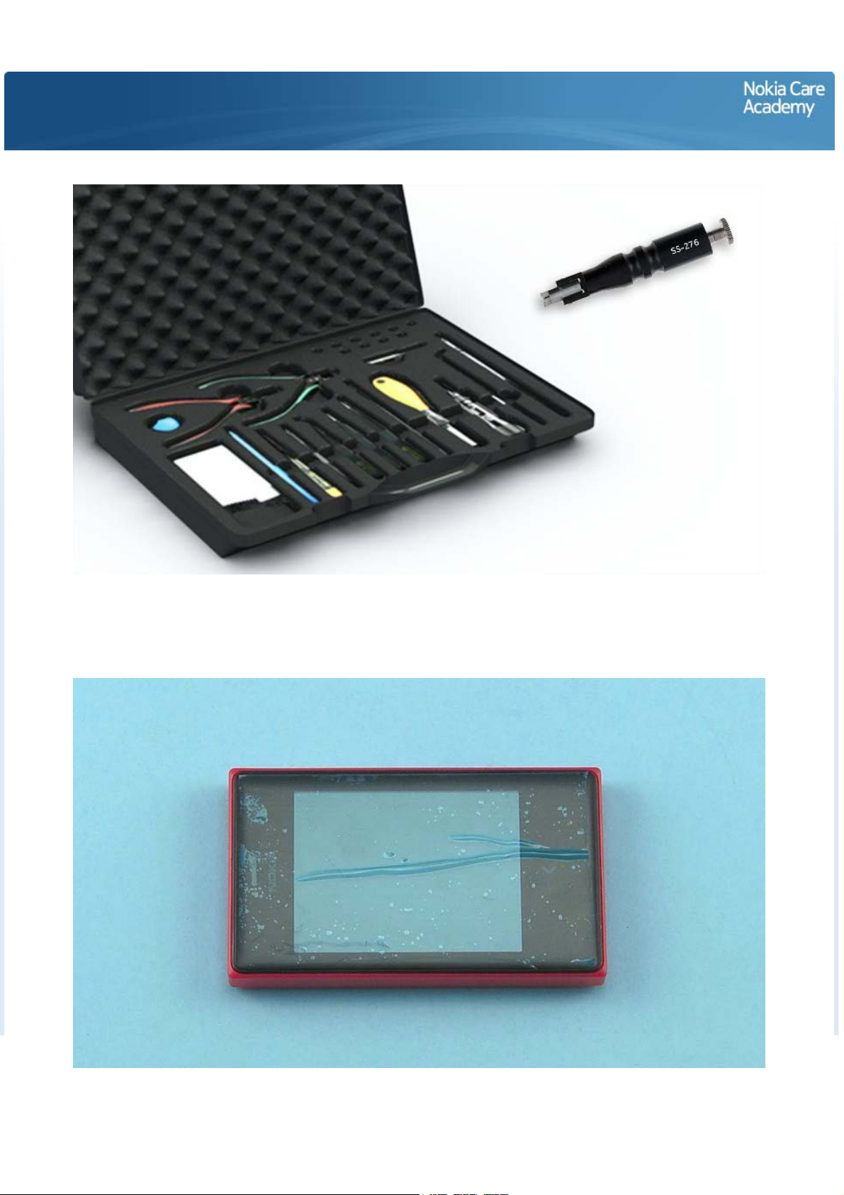
1) For disassembling you need the Nokia Standard toolkit version 2. You will also need the camera
removal tool SS-276. Please note that the phone used in disassembly and assembly is a prototype
phone and does not look like the sales model.
2) Protect the TOUCH WINDOW with protective film.
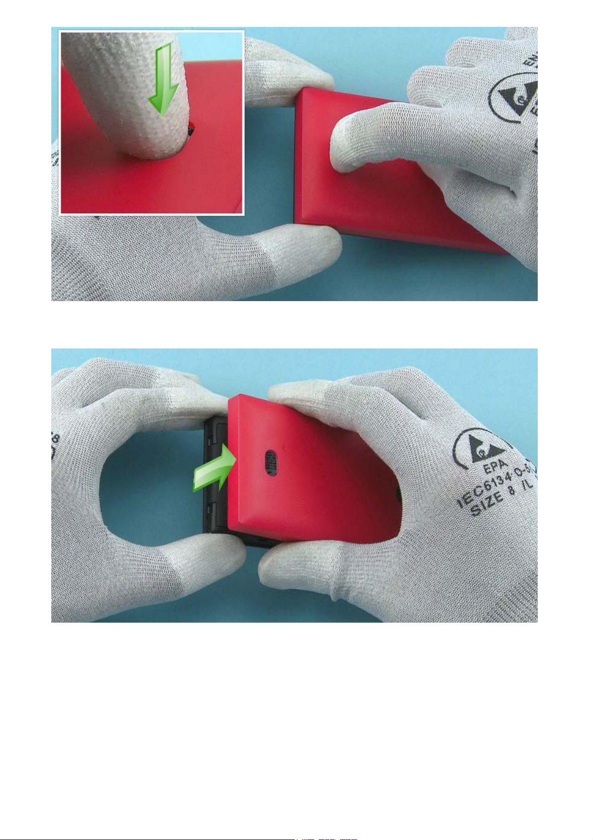
3) Release the B-COVER by pushing down the RELEASE BUTTON.
4) Remove the B-COVER bottom end first
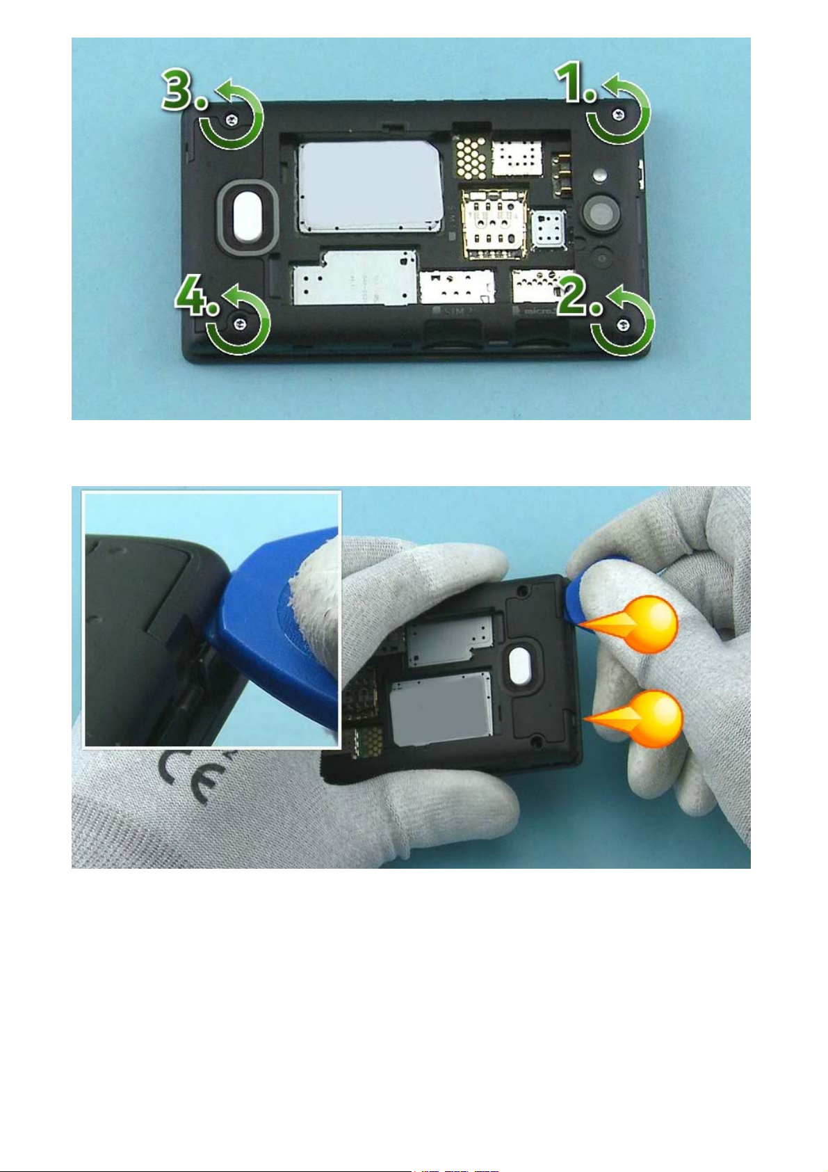
5) Unscrew the four Torx+ size 6 screws in the order shown.
6) Release the two shown clips of the D-COVER with the SRT-6.
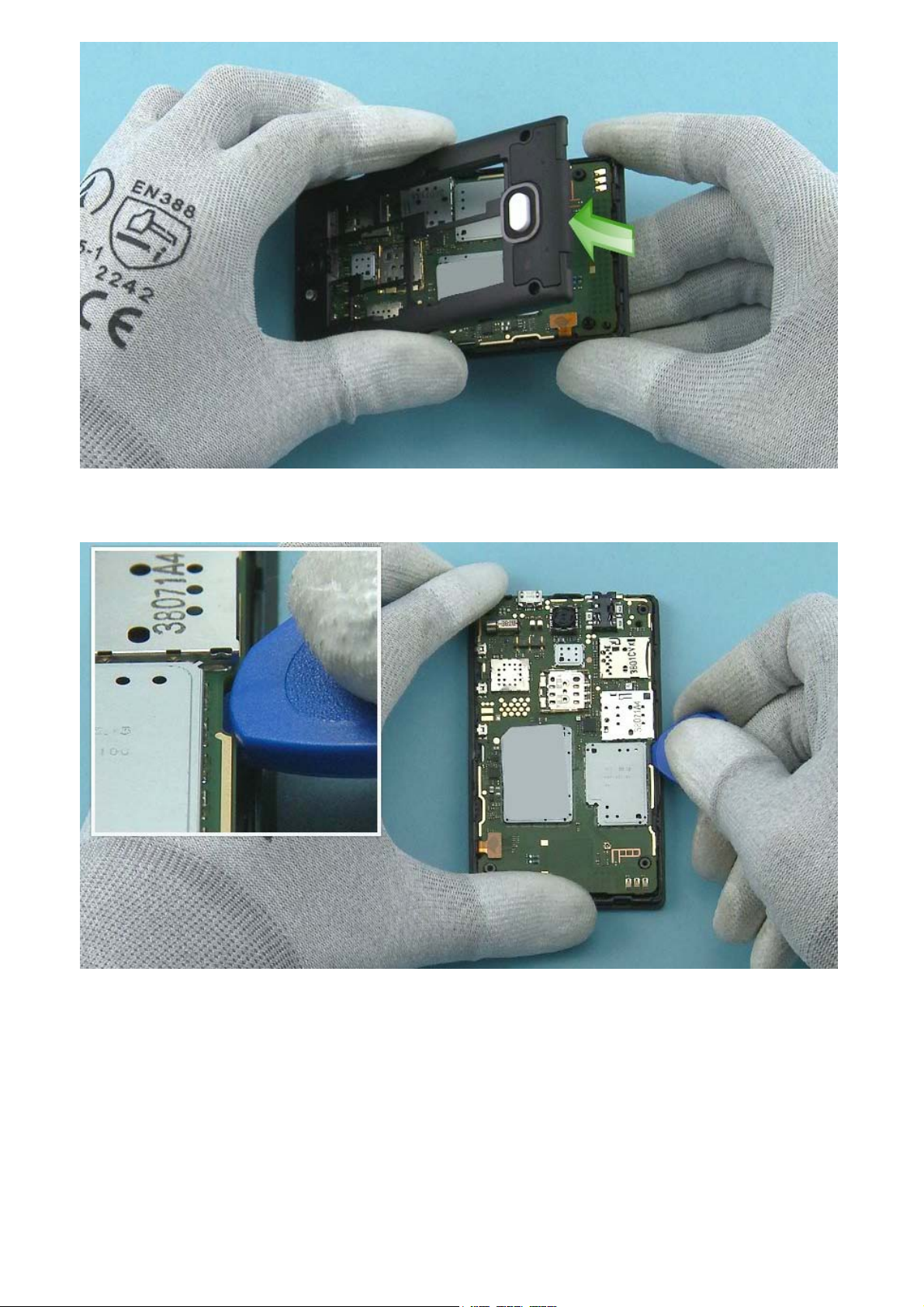
7) Remove the D-COVER bottom end first.
8) Release the ENGINE BOARD from the shown place with the SRT-6.
 Loading...