

Page 1

1508i(RM-430)
Antenna Description and Troubleshooting
Nokia Customer Care
Nokia Customer Care
1508i (RM-430)
Mobile Terminal
Antenna Description and
Troubleshooting
Issue 1
Copyright © 2008 Nokia, All rights reserved
Page 2

1508i(RM-430)
Antenna Description and Troubleshooting
Nokia Customer Care
Contents
Antenna Troubleshooting
Issue 1
Copyright © 2008 Nokia, All rights reserved
Page 3
1508i(RM-430)
Antenna Description and Troubleshooting
Nokia Customer Care
Introduction
The mobile terminal includes an internal antenna. This antenna arrangement is used for
PCS frequency bands. The internal antenna assembly adopts Monopole Antenna
structure used for the PCS engine.
Visual Quality Requirements
Below are the minimum acceptable visual quality requirements of the internal antenna
assembly:
z Wear gloves to assemble the antenna. Don’t touch the antenna radiator with bare
hands.
z No visual cracks or mechanical defects.
z No oil, dirt, or particles are present on the parts.
z Radiator must be aligned with the plastic housing.
z Radiator must be flat with no warping.
z The length of all pins must be identical and the pins align.
Failures and Corrective Measures
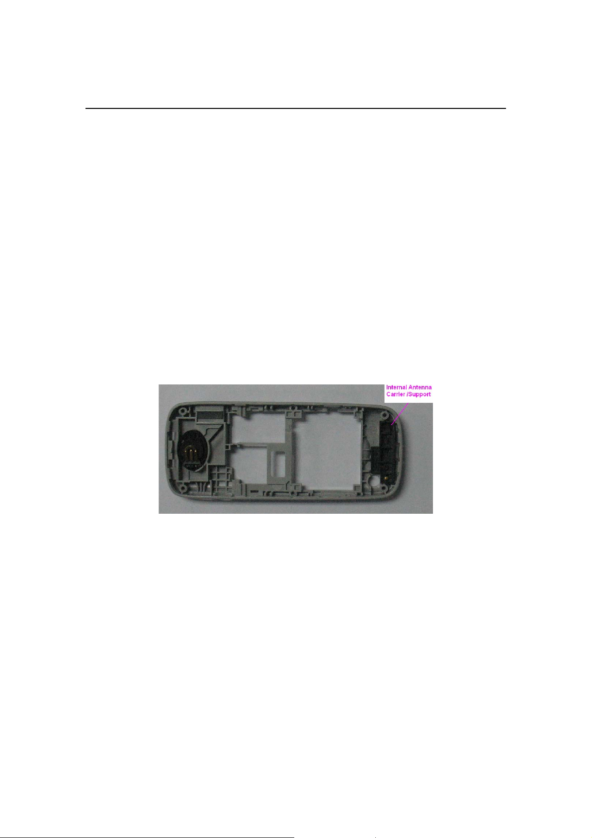
The internal antenna is assembled into the Back Cover Assembly as shown in Figure 1.
If no internal antenna is installed, the antenna gain is degraded by more than 20 dB.
z If the internal antenna is missing, install antenna-asm Module.
z If the radiator looks damaged, replace it with a new antenna–asm Module.
Figure 1: B Cover Assembly
Issue 1
Copyright © 2008 Nokia, All rights reserved
Page 4

1508i(RM-430)
Antenna Description and Troubleshooting
Nokia Customer Care
Monopole Antenna
The internal antenna has a monopole antenna radiator attached to the plastic support.
Figure 2: The top view of internal antenna
Damaged RF feed point Pin
The pin (spring clip) of the antenna must be properly connected to the PWB.
z If the main antenna’s RF feed point pin does not touch the PWB, the antenna gain
degrades by more than 17 dB.
z If the RF feed pin is broken or bent so that the pin does not touch the PWB, replace
the antenna-asm Module.
z If the RF feed pin spring appears damaged, replace the antenna-asm Module.
Figure 3: back view of internal antenna
Issue 1
Copyright © 2008 Nokia, All rights reserved
Page 5

1508i(RM-430)
Antenna Description and Troubleshooting
Nokia Customer Care
Obstructed RF feed point pad
If RF feed point pad is obstructed, removed, or covered, the antenna pin does not touch
the PWB and the cellular antenna performance degrades.
z If corrosion is present or the pad is missing, replace the PWB.
z If a pad is obstructed or covered by something, clear and/or clean the pad.
z If any component of antenna match circuit is missing ,replace the PWB
Figure 4: PWB layout of RF feed point and antenna match circuit
Issue 1
Copyright © 2008 Nokia, All rights reserved
Page 6

1508i(RM-430)
Antenna Description and Troubleshooting
Nokia Customer
Care
RF Connector Failure
The RF connector fails when it does not properly connect the RF input terminal to the
RF output terminal during the SMT. If this happens the antenna gain degrades by 25
dB. Check this by testing the resistance value between the RF input and RF output of
the RF connector and see if the value is close to zero. If the RF input is not
connected properly to the RF output, replace the RF connector.
Note: Perform the resistance value test without a RF cable attached to the RF
connector. Because the RF connector is also a switch, the RF output is
disconnected from the RF input when RF cable is inserted into the RF connector.
z RF input terminal – connect to duplexer.
z RF output terminal – connect to the antenna pad through antenna match
circuit.
z RF connector terminal – connect to RF coaxial cable.
Figure 6: RF input / output terminal
Issue 1
Copyright © 2008 Nokia, All rights reserved
 Loading...