

Page 1

Nokia Customer Care
1255(RH-79)/1315(RH-96)/1265(RH-103)/
1325(RH-104)/6066(RM-211)/6088(RM-218)/
7088(RM-219)/2505(RM-307)
Mobile Terminal
Service Software Instructions
Issue 1 01/2007 Company Confidential © 2007 Nokia Corporation
Page 2

1255/1265/1315/1325/2505/6066/6088/7088
Service Software Instructions
Contents Page
Introduction............................................................................................................... 4
Hardware, Operating System and Environment Requirements.........................4
Installation.........................................................................................................5
Uninstall...........................................................................................................20
Service Software.................................................................................................... 26
Before You Begin.............................................................................................26
Initial Session with Service Software and Scanning for a Product...................26
Using Components..........................................................................................27
Login....................................................................................................................... 28
Login Account..................................................................................................28
SPC verification...............................................................................................28
Use..................................................................................................................28
Phone Information.................................................................................................. 31
Use..................................................................................................................31
Flashing.................................................................................................................. 33
Use..................................................................................................................33
Bundle Flashing...................................................................................................... 37
Use..................................................................................................................37
User data transfer................................................................................................... 39
Use..................................................................................................................39
Load Default........................................................................................................... 41
Use..................................................................................................................41
Service Programming............................................................................................. 42
Use..................................................................................................................42
Setting Items ...................................................................................................43
CDMA1 Items..................................................................................................45
CDMA2 Items..................................................................................................46
Flexible graphics and tones.................................................................................... 48
Use..................................................................................................................48
SID.......................................................................................................................... 52
Use..................................................................................................................52
Testing.................................................................................................................... 54
Use..................................................................................................................54
Self Tests.........................................................................................................54
Display ............................................................................................................55
Keypad............................................................................................................55
Page 2 © 2007 Nokia Corporation Company Confidential Issue 1 01/2007
Page 3

1255/1265/1315/1325/2505/6066/6088/7088
Nokia Customer Care Service Software Instructions
Camera ...........................................................................................................57
Stereo Audio/Vibrator ......................................................................................57
Path Loss ........................................................................................................59
RF Calibration .................................................................................................60
RF Tool............................................................................................................62
Call Test...........................................................................................................67
Memory Capture..................................................................................................... 69
Use..................................................................................................................69
Label Printing.......................................................................................................... 70
Use..................................................................................................................70
Appendix A. Procedure of reviving a dead phone.................................................. 72
Appendix B. Procedure of multi-flashing Part I...................................................... 74
Appendix C. Procedure of multi-flashing Part II.....................................................76
Issue 1 01/2007 © 2007 Nokia Corporation Company Confidential Page 3
Page 4
1255/1265/1315/1325/2505/6066/6088/7088
Service Software Instructions
Introduction
In order to use service software for 1255, 1265, 1315, 1325, 6066, 6088, 7088
and 2505, service technician should read this chapter in detail to know service hardware,
NI environment and drivers requirement to get them well setup in service computer and
ensure service software can run well to service returned phones.
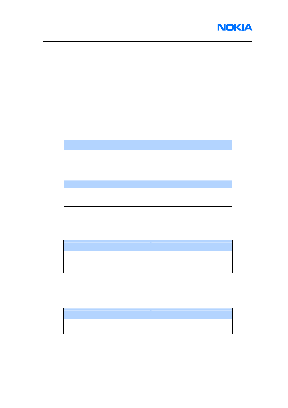
Hardware, Operating System and Environment Requirements
Refer to Table1 for minimum service hardware requirement.
Operating System Requirements: Windows 2000, Windows XP
Service PC Minimum Requirement
Processor 700MHz
RAM 256MB
Required Disk space 100MB
Interface ports USB or Serial
Callbox Minimum Requirement
E5515C-003 Module or E1962B
Agilent 8960
ROHDE & SCHWARZ CMU200 B83/K84 Module
module with firmware version
B.07.15 or later
Table 1: Minimum Hardware Requirements
Refer to Table2 for minimum NI Environment requirement.
NI Environment Minimum Requirement
NI-488.2 (GPIB driver included) version 2.4 or later
NI-VISA & NI-VISA runtime version 3.4.1 or later
Labwindows/CVI Run-Time engine version 8.0 or later
Table 2: Minimum NI Environment Requirements
Refer to Table3 for minimum driver installation requirement.
Driver Minimum Requirement
PK-83 AMS Software Protection Key version 7.1.0 or later
Qualcomm USB host driver version 2.0.2.0 or later
Table 3: Minimum Driver Installation Requirements
Page 4 © 2007 Nokia Corporation Company Confidential Issue 1 01/2007
Page 5
1255/1265/1315/1325/2505/6066/6088/7088
Nokia Customer Care Service Software Instructions
Installation
Please follow below detailed instructions for installing 1255, 1265, 1315, 1325,
6066, 6088, 7088 and 2505 service software. There are 3 major parts in the service
software – the service software, NI Environment and drivers, which need to be installed
separately. If your PC already has these drivers and NI Environment installed, you can
skip the installation procedure.
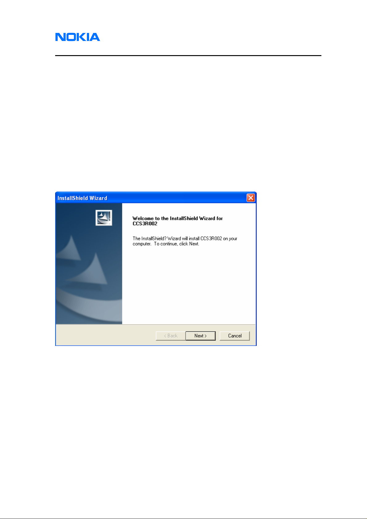
1. Service Software
1.1. Please find the released zip file CCS12RXXX.zip for level 1 and 2 or
CCS3RXXX.zip for level 3 (X represents version number). Unzip all files to one
folder and save them to any directory in service computer. Open the folder and
open the executable file (Setup.exe). Double click it to start installing or uninstalling
service software. Click on “Next” button.
Issue 1 01/2007 © 2007 Nokia Corporation Company Confidential Page 5
Page 6
1255/1265/1315/1325/2505/6066/6088/7088
Service Software Instructions
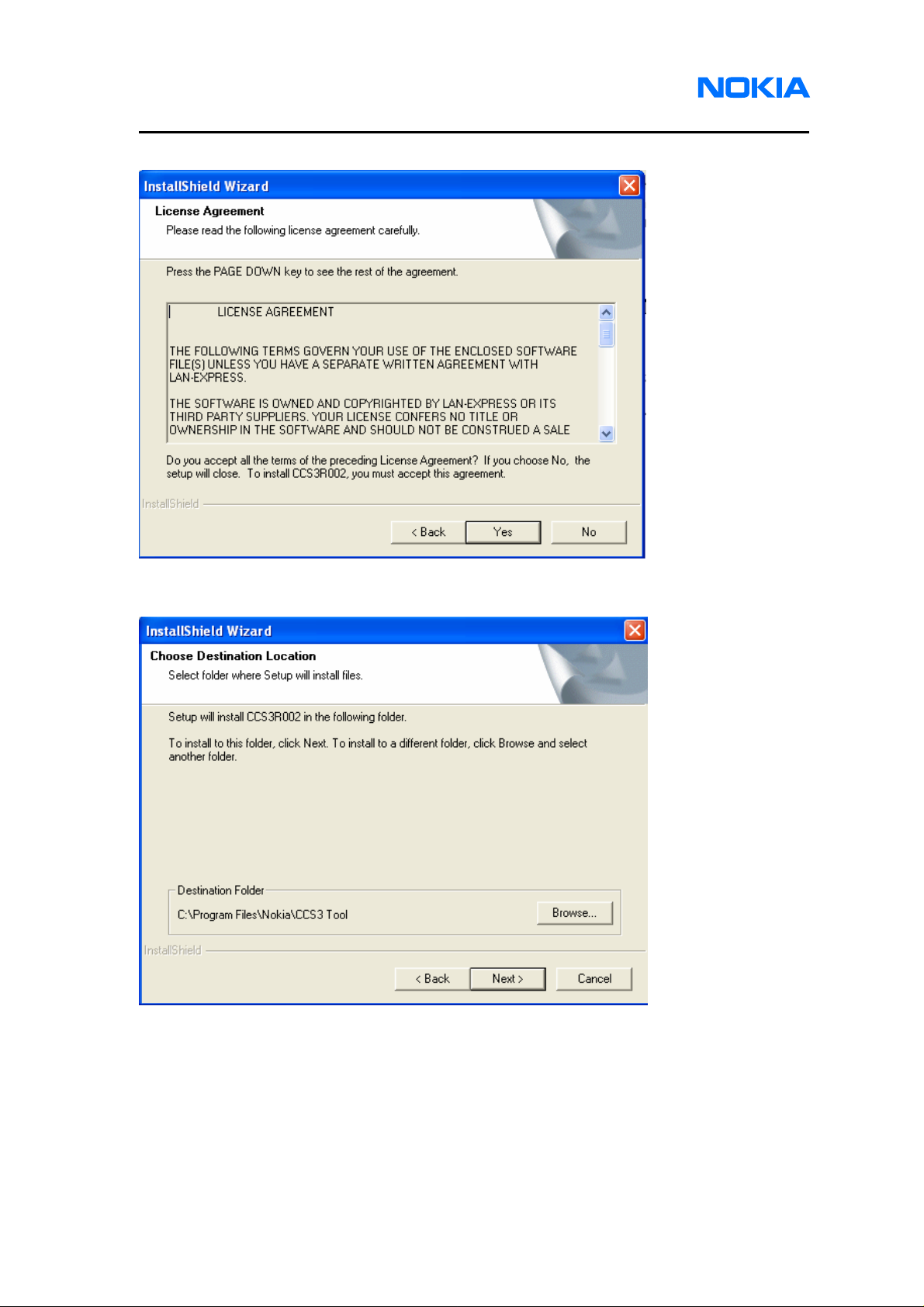
1.2. License Agreement of Service Software appears. Click on “Yes” button.
1.3. Choose a Destination Location. Browse to identify a folder in your PC, or click on
“Next” button to save the setup files in the default location.
Page 6 © 2007 Nokia Corporation Company Confidential Issue 1 01/2007
Page 7
1255/1265/1315/1325/2505/6066/6088/7088
Nokia Customer Care Service Software Instructions
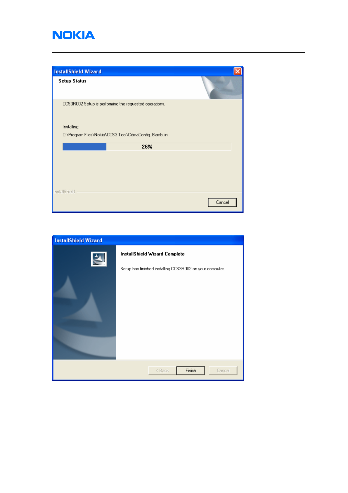
1.4. Waiting for the installing to complete.
1.5. The service software has been successfully installed. Click on “Finish” button.
Issue 1 01/2007 © 2007 Nokia Corporation Company Confidential Page 7
Page 8
1255/1265/1315/1325/2505/6066/6088/7088
Service Software Instructions
2. NI Environment
2.1. It’s necessary to install NI Environment for running RF related testing function.
2.2. Install NI-488.2 by using NI driver CD #1 which is provided by Nation Instrument. If
you would like to get any NI software, please go to www.ni.com
“support->drivers and updates” to download software module.
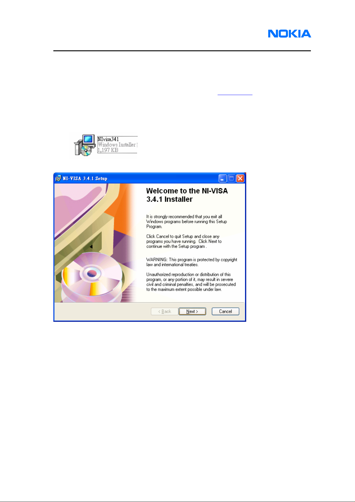
2.3. Open the file “NIvisa341.msi” which is included in Software Installation files to
install NI-VISA driver.
2.4. Click on “Next” button.
under the link
Page 8 © 2007 Nokia Corporation Company Confidential Issue 1 01/2007
Page 9
1255/1265/1315/1325/2505/6066/6088/7088
Nokia Customer Care Service Software Instructions
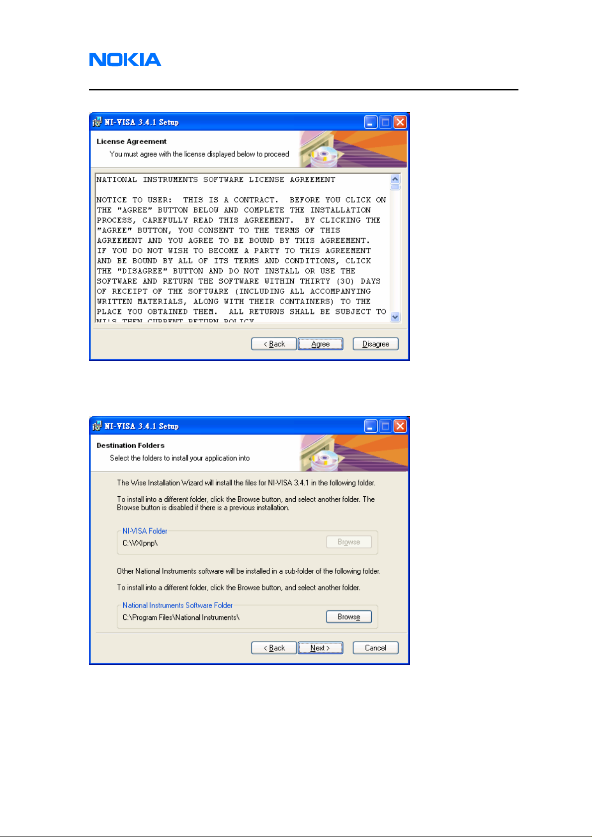
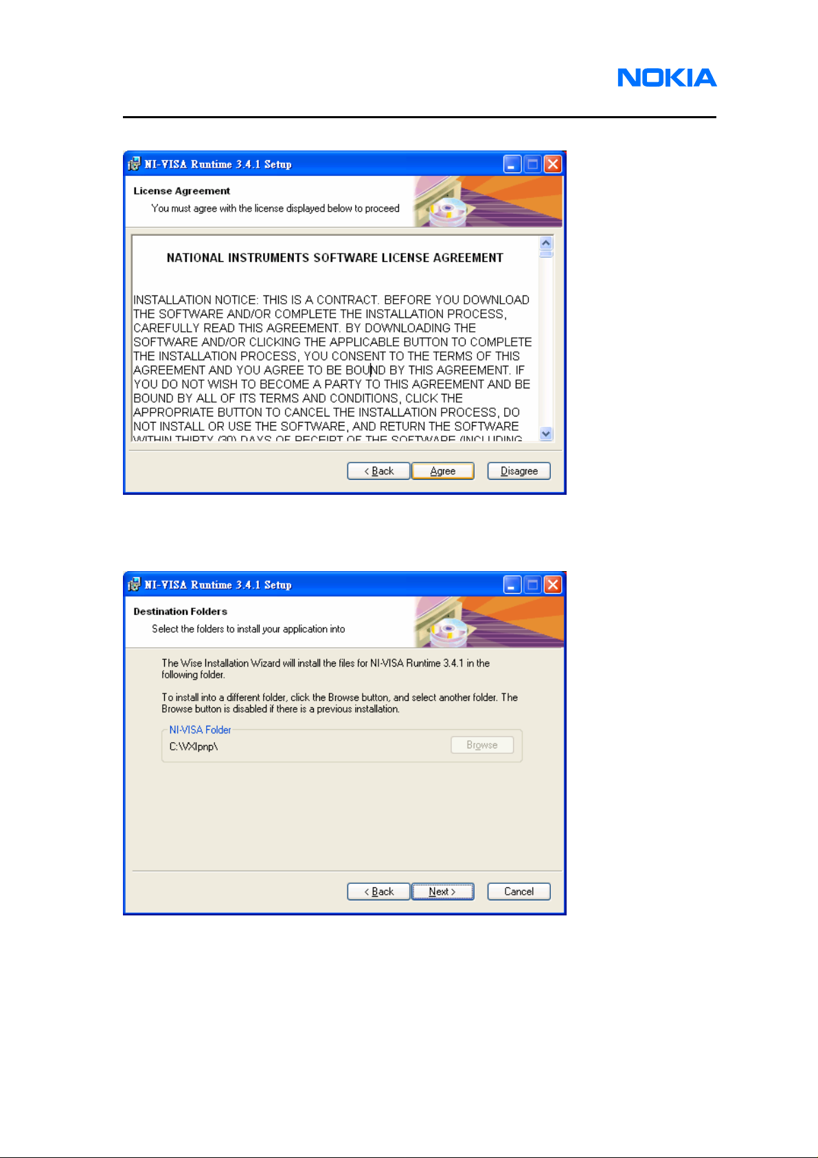
2.5. License Agreement pops up. Click on “Agree” button for the next step.
2.6. Choose a Destination Location. Browse to identify a folder in your PC, or click on
“Next” button to save the setup files in the default location.
Issue 1 01/2007 © 2007 Nokia Corporation Company Confidential Page 9
Page 10
1255/1265/1315/1325/2505/6066/6088/7088
Service Software Instructions
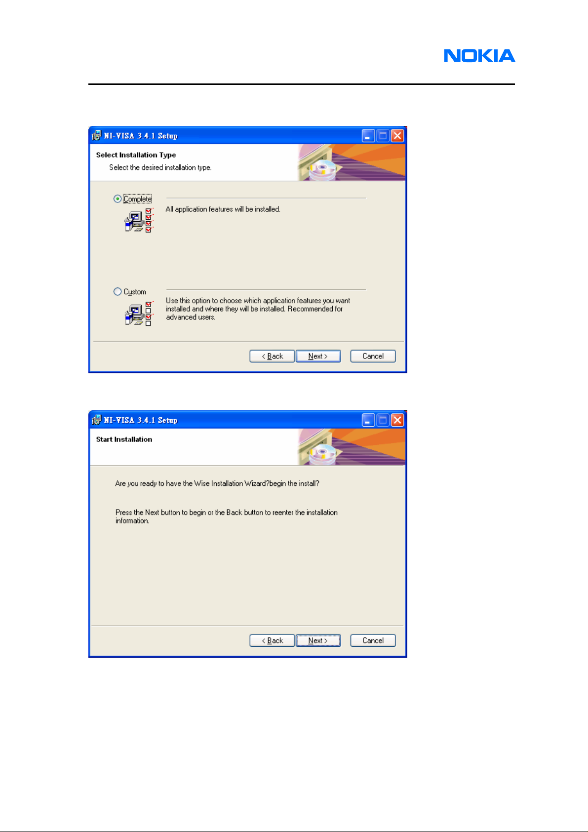
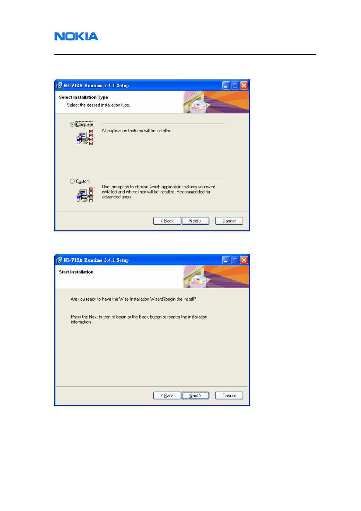
2.7. Select Installation Type. You are recommended to select “Complete” and click on
“Next” button.
2.8. Click on “Next” button and wait for installing.
Page 10 © 2007 Nokia Corporation Company Confidential Issue 1 01/2007
Page 11
1255/1265/1315/1325/2505/6066/6088/7088
Nokia Customer Care Service Software Instructions
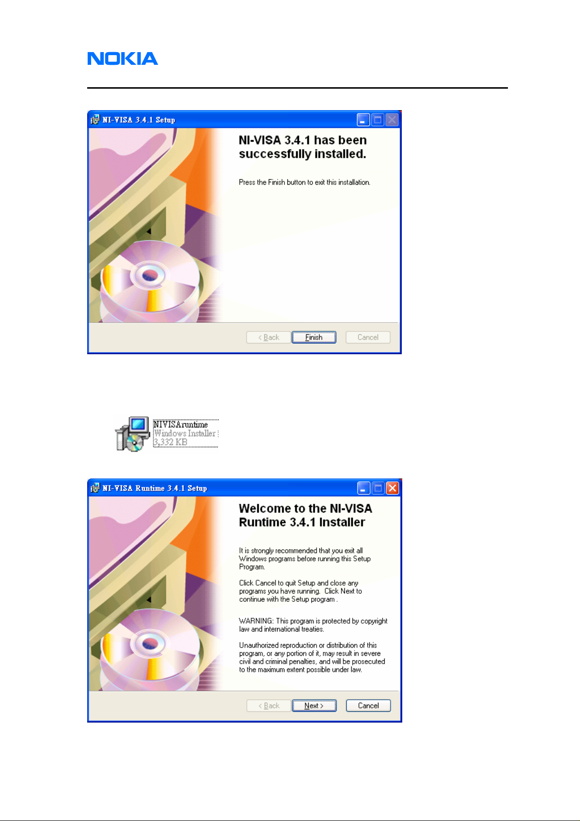
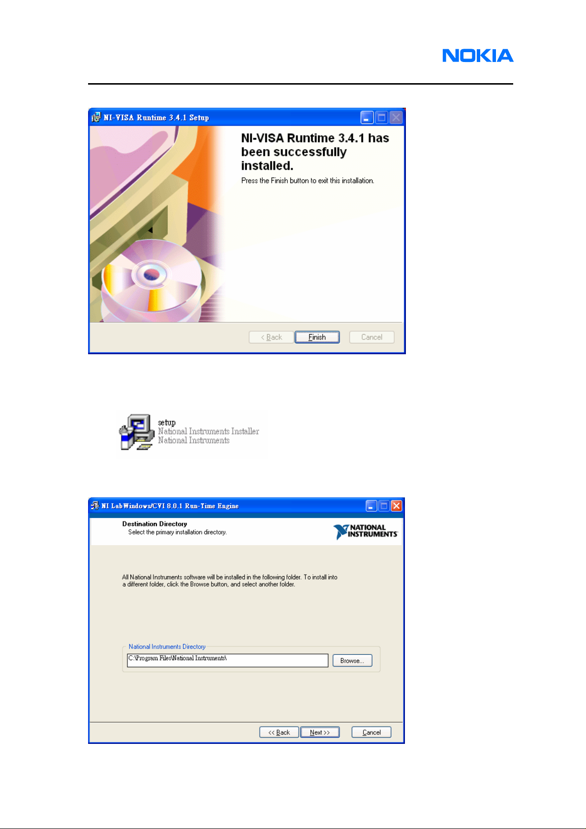
2.9. NI-VISA has been successfully installed. Click on “Finish” button.
2.10. Open the file “NIVISAruntime.msi” which is included in Software Installation files to
install NI-VISA Runtime library.
2.11. Click on “Next” button.
Issue 1 01/2007 © 2007 Nokia Corporation Company Confidential Page 11
Page 12
1255/1265/1315/1325/2505/6066/6088/7088
Service Software Instructions
2.12. License Agreement pops up. Click on “Agree” button for the next step.
2.13. Choose a Destination Location. Browse to identify a folder in your PC, or click on
“Next” button to save the setup files in the default location.
Page 12 © 2007 Nokia Corporation Company Confidential Issue 1 01/2007
Page 13
1255/1265/1315/1325/2505/6066/6088/7088
Nokia Customer Care Service Software Instructions
2.14. Select Installation Type. You are recommended to select “Complete” and click on
“Next” button.
2.15. Click on “Next” button and wait for installing.
Issue 1 01/2007 © 2007 Nokia Corporation Company Confidential Page 13
Page 14
1255/1265/1315/1325/2505/6066/6088/7088
Service Software Instructions
2.16. NI-VISA Runtime library has been successfully installed. Click on “Finish” button.
2.17. Open the file “setup.exe” which is included in Software Installation files to install NI
Labwindows/CVI Run-Time engine.
2.18. Choose a Destination Location. Browse to identify a folder in your PC, or click on
“Next” button to save the setup files in the default location.
Page 14 © 2007 Nokia Corporation Company Confidential Issue 1 01/2007
Page 15
1255/1265/1315/1325/2505/6066/6088/7088
Nokia Customer Care Service Software Instructions
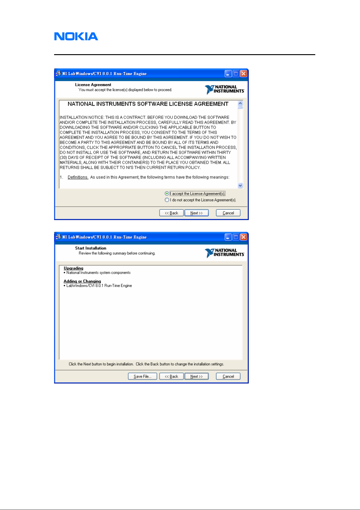
2.19. License Agreement pops up. Click on “Agree” button for the next step.
2.20. Click on “Next” button and wait for installing.
Issue 1 01/2007 © 2007 Nokia Corporation Company Confidential Page 15
Page 16
1255/1265/1315/1325/2505/6066/6088/7088
Service Software Instructions
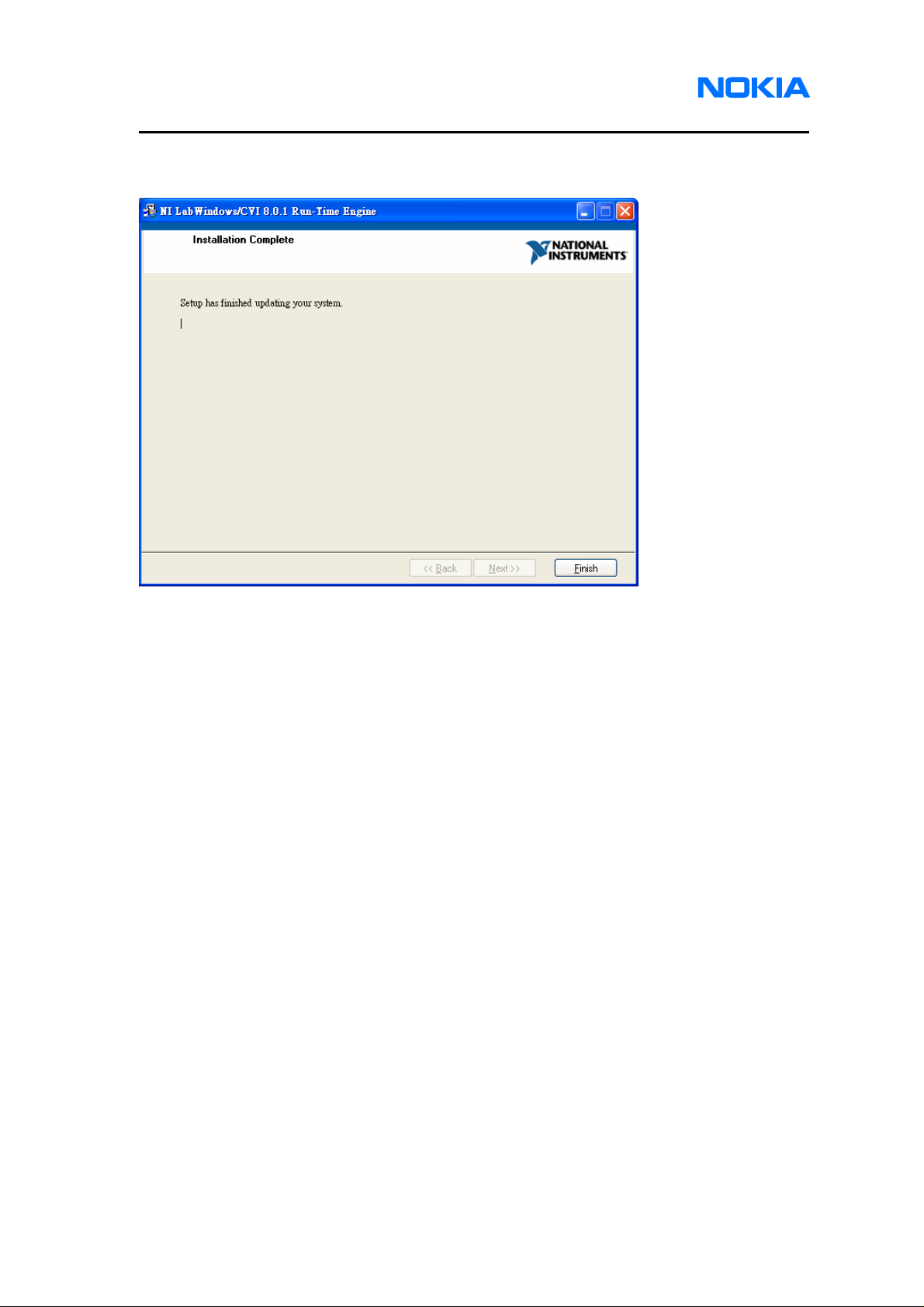
2.21. Labwindows/CVI Run-Time engine has been successfully installed. Click on
“Finish” button.
Page 16 © 2007 Nokia Corporation Company Confidential Issue 1 01/2007
Page 17
1255/1265/1315/1325/2505/6066/6088/7088
Nokia Customer Care Service Software Instructions
3. Drivers
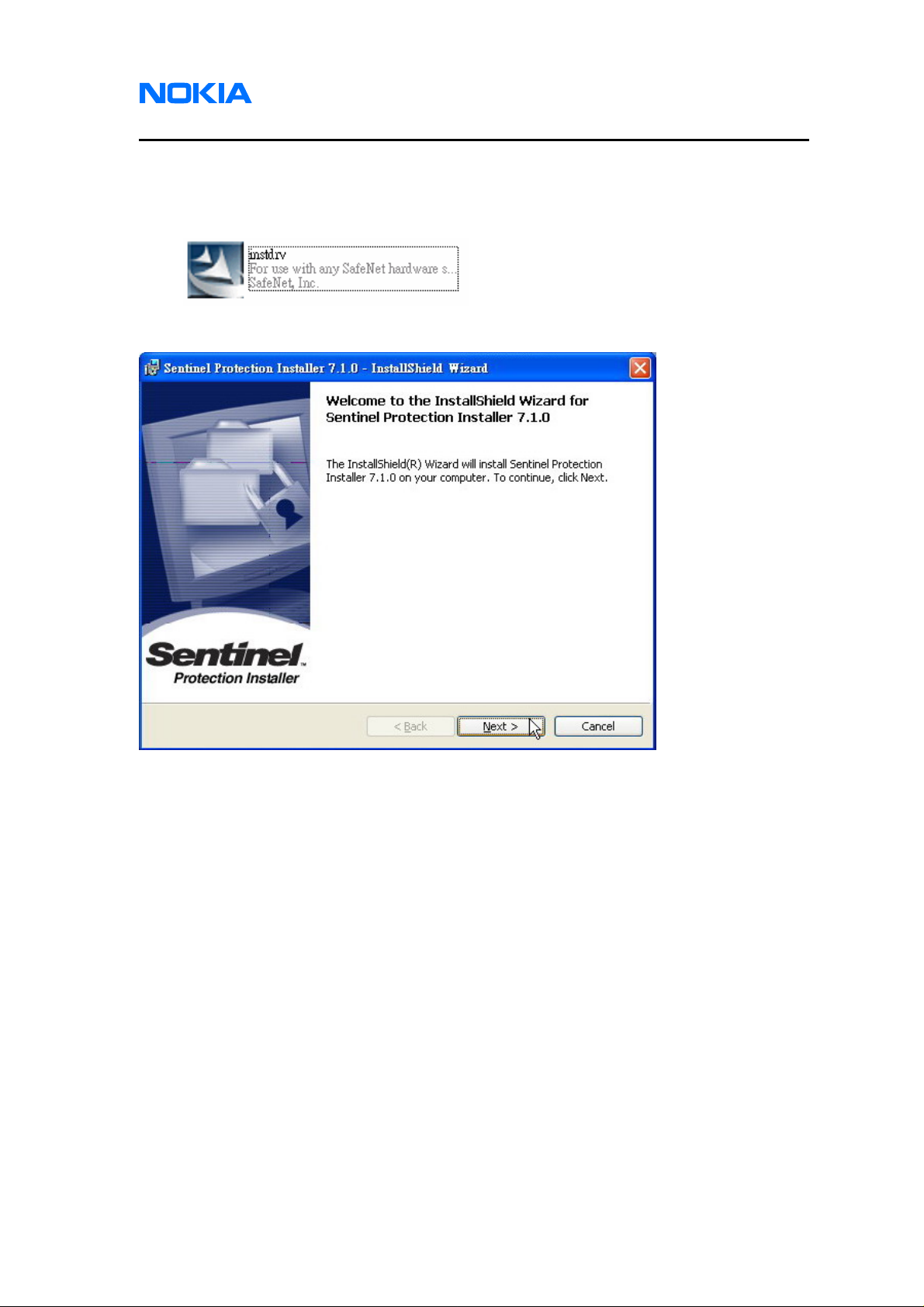
3.1. Open the file “instdrv” which is included in Software Installation files to install AMS
Software Protection Key driver.
3.2. Click on “Next” button.
Issue 1 01/2007 © 2007 Nokia Corporation Company Confidential Page 17
Page 18
1255/1265/1315/1325/2505/6066/6088/7088
Service Software Instructions
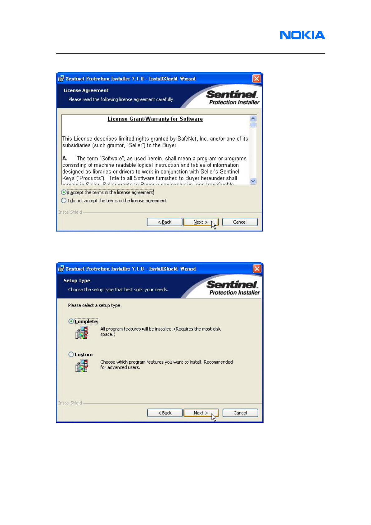
3.3. Click on “Next” button.
3.4. Select “Complete” and click on “Next” button.
Page 18 © 2007 Nokia Corporation Company Confidential Issue 1 01/2007
Page 19
1255/1265/1315/1325/2505/6066/6088/7088
Nokia Customer Care Service Software Instructions
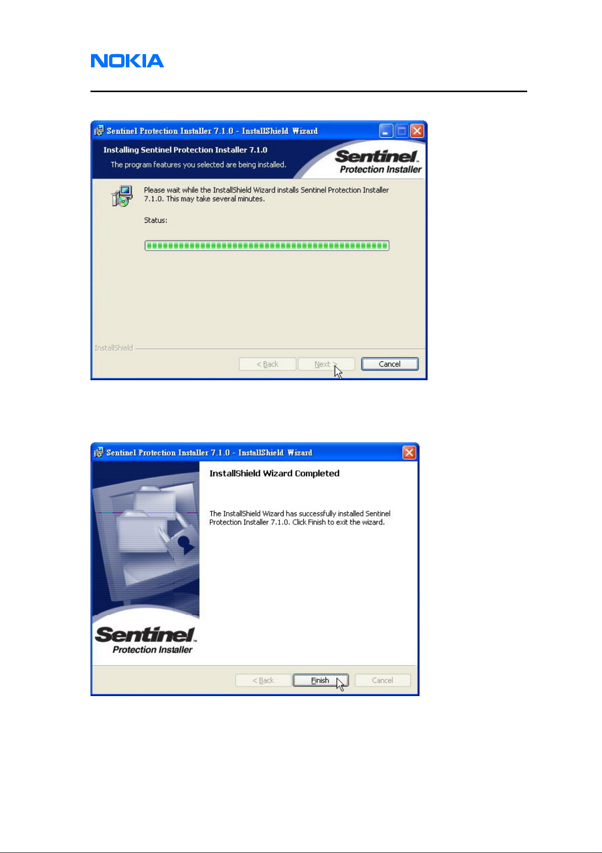
3.5. Waiting for installing AMS Software Protection Key driver.
3.6. AMS Software Protection Key driver has been successfully installed. Click on
“Finish” button.
Issue 1 01/2007 © 2007 Nokia Corporation Company Confidential Page 19
Page 20
1255/1265/1315/1325/2505/6066/6088/7088
Service Software Instructions
Uninstall
Please follow below detailed instructions to uninstall the service software. Same
as installation, service software, USB driver, NI-VISA and AMS Software Protection Key
driver needed to be uninstalled separately.
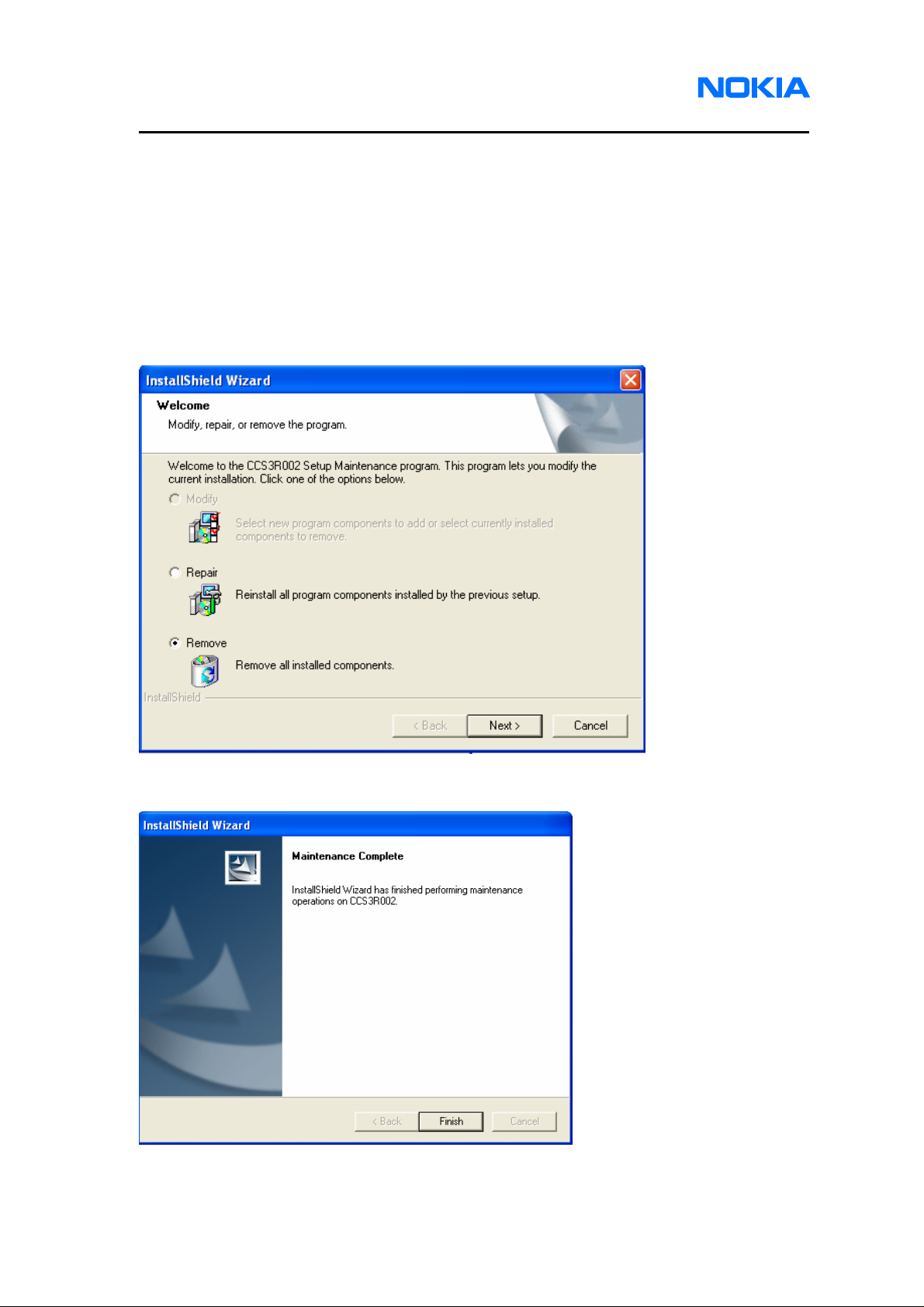
1. Service Software
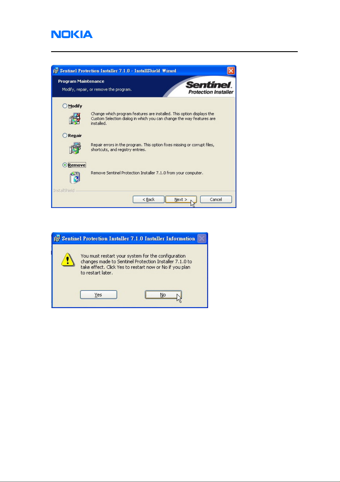
1.1. Open the executable file (Setup.exe) which is included in Service Software
Installation Package. Select “Remove” and click on “Next” button.
1.2. Click on “Finish” button to finish uninstalling the service software.
Page 20 © 2007 Nokia Corporation Company Confidential Issue 1 01/2007
Page 21

1255/1265/1315/1325/2505/6066/6088/7088
Nokia Customer Care Service Software Instructions
2. NI Environment
2.1. Open the file “NIvisa341.msi” which is included in Software Installation Package to
uninstall NI-VISA driver
2.2. Click on “Remove All” to uninstall NI-VISA driver.
2.3. Click on “Next” button and wait for uninstalling.
Issue 1 01/2007 © 2007 Nokia Corporation Company Confidential Page 21
Page 22
1255/1265/1315/1325/2505/6066/6088/7088
Service Software Instructions
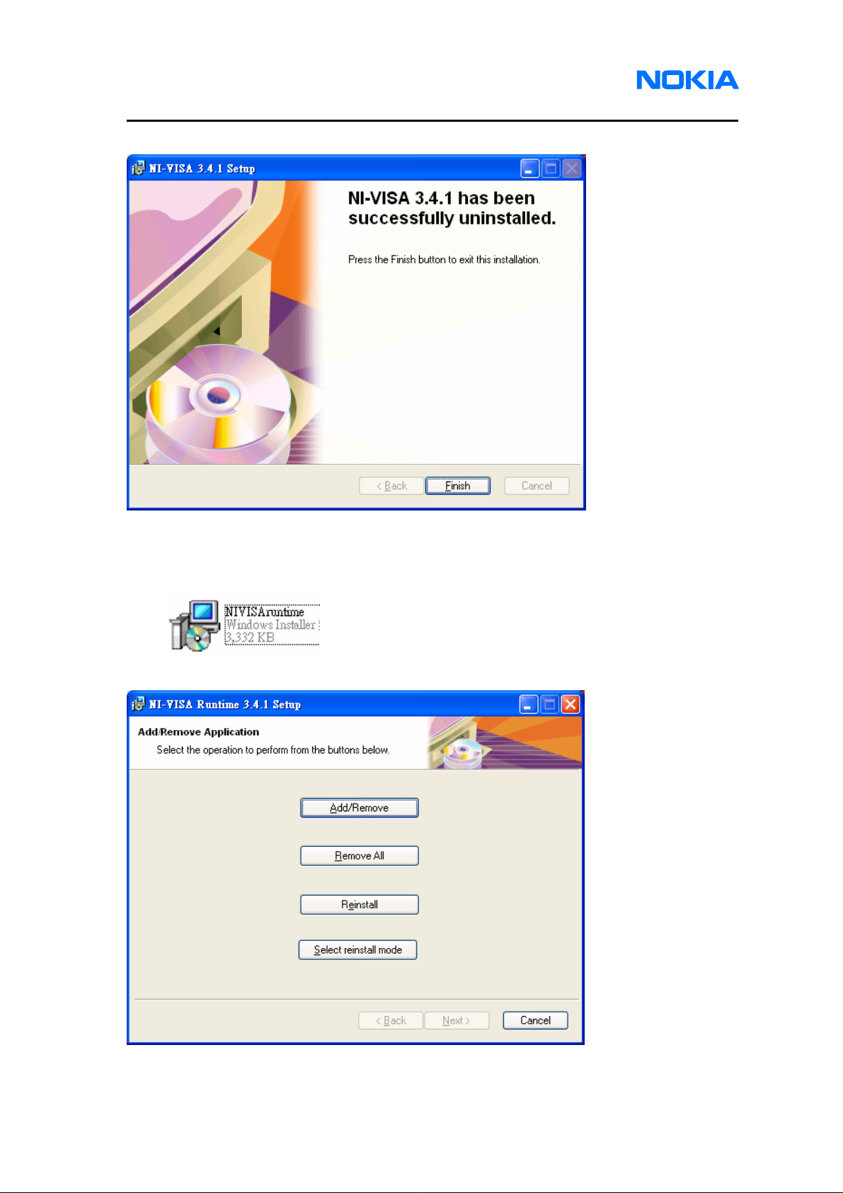
2.4. Click on “Finish” button to finish uninstalling NI-VISA driver.
2.5. Open the file “NIVISAruntime.msi” which is included in Software Installation
Package to uninstall NI-VISA runtime library.
2.6. Click on “Remove All” to uninstall NI-VISA runtime library.
Page 22 © 2007 Nokia Corporation Company Confidential Issue 1 01/2007
Page 23
1255/1265/1315/1325/2505/6066/6088/7088
Nokia Customer Care Service Software Instructions
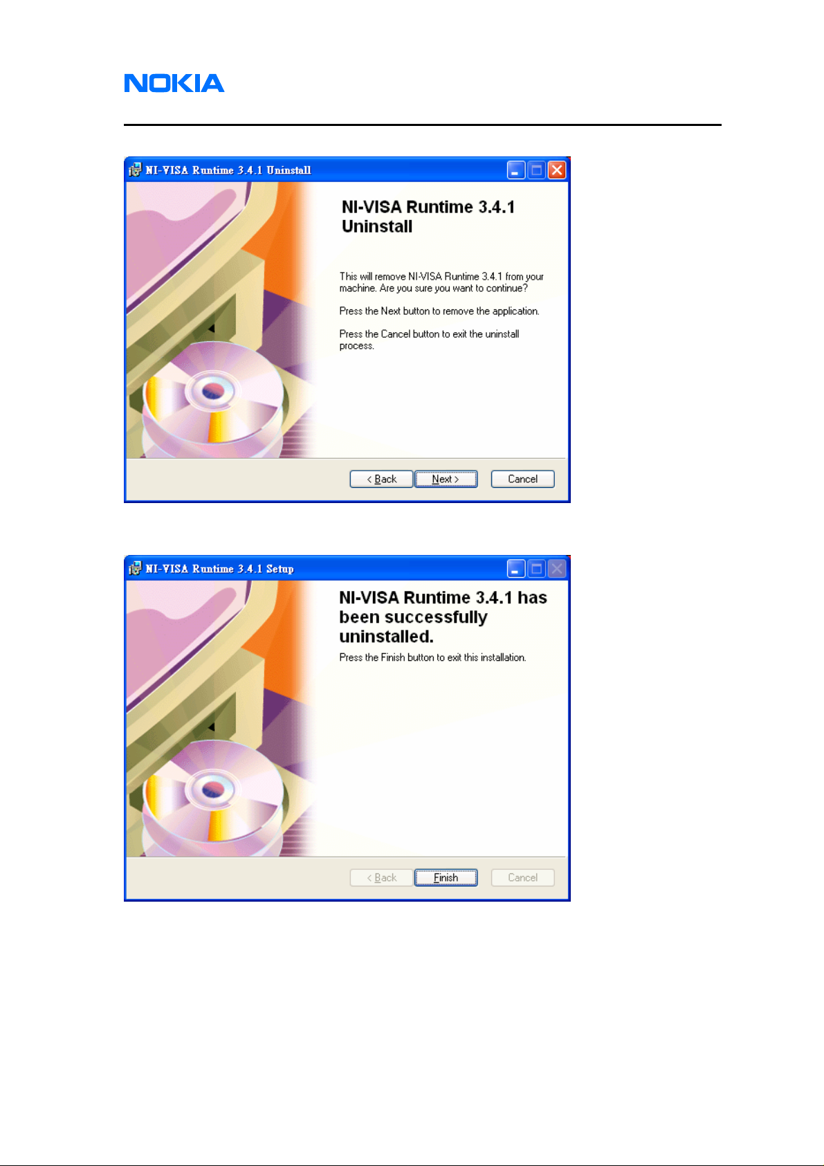
2.7. Click on “Next” button and wait for uninstalling.
2.8. Click on “Finish” button to finish uninstalling NI-VISA runtime library.
Issue 1 01/2007 © 2007 Nokia Corporation Company Confidential Page 23
Page 24
1255/1265/1315/1325/2505/6066/6088/7088
Service Software Instructions
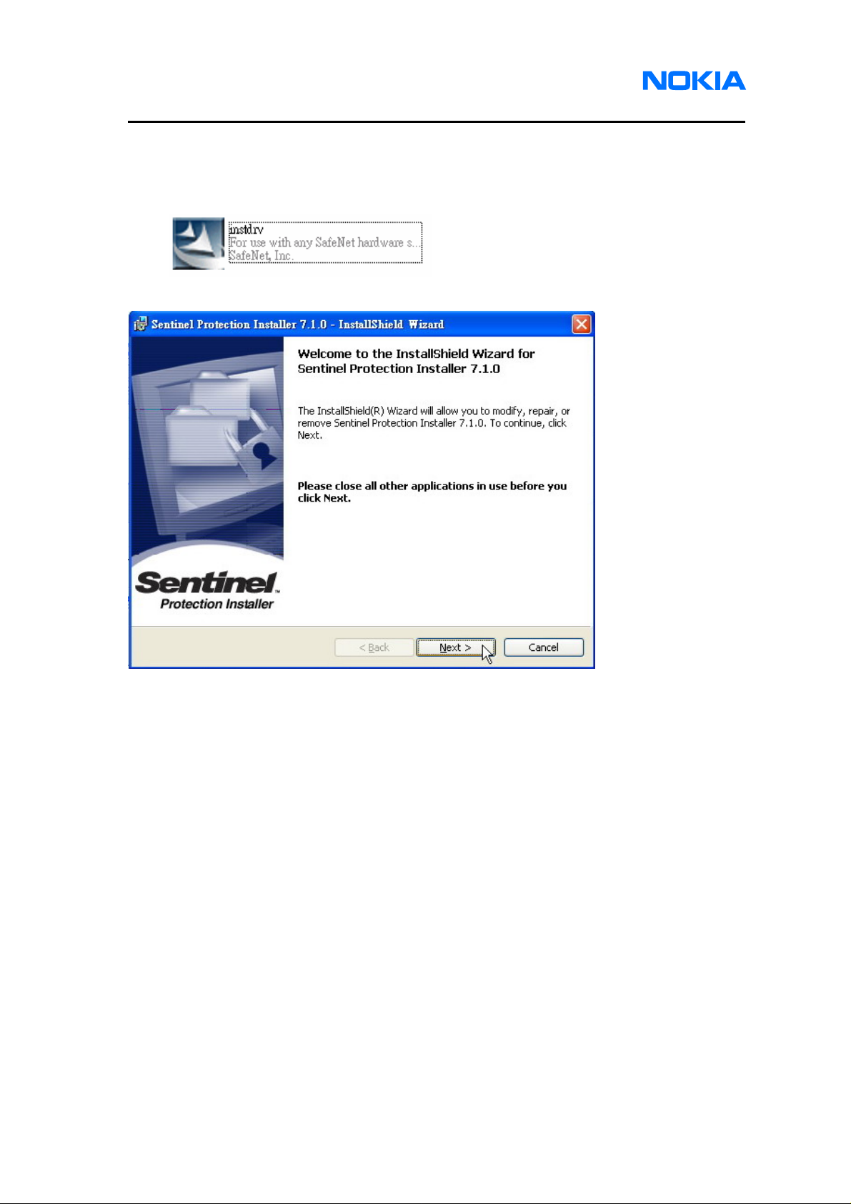
3. Drivers
3.1. Open the file “instdrv” which is included in Software Installation files to uninstall
AMS Software Protection Key driver.
3.2. Click on “Next” to start uninstall AMS Software Protection Key driver.
Page 24 © 2007 Nokia Corporation Company Confidential Issue 1 01/2007
Page 25
1255/1265/1315/1325/2505/6066/6088/7088
Nokia Customer Care Service Software Instructions
3.3. Select “Remove” and click on “Next” button.
3.4. If the following warning appears, please click on “Yes” button to restart system.
Issue 1 01/2007 © 2007 Nokia Corporation Company Confidential Page 25
Page 26
1255/1265/1315/1325/2505/6066/6088/7088
Service Software Instructions
Service Software
Before You Begin
Before using the Service Software, level 1 and 2 users should acquire the
username and password from the provider, while level 3 users needs to acquire specific
AMS Software Protection Key. The authentication information is required when you login
to the system. Service software will provide different functionalities and software
components on the basis of your service level.
Initial Session with Service Software and Scanning for a Product
Service software will automatically capture all connections to which the mobile
terminal is connected. You can start connecting to the mobile terminal by selecting a
COM port identified on the screen.
Follow the steps below to select a port:
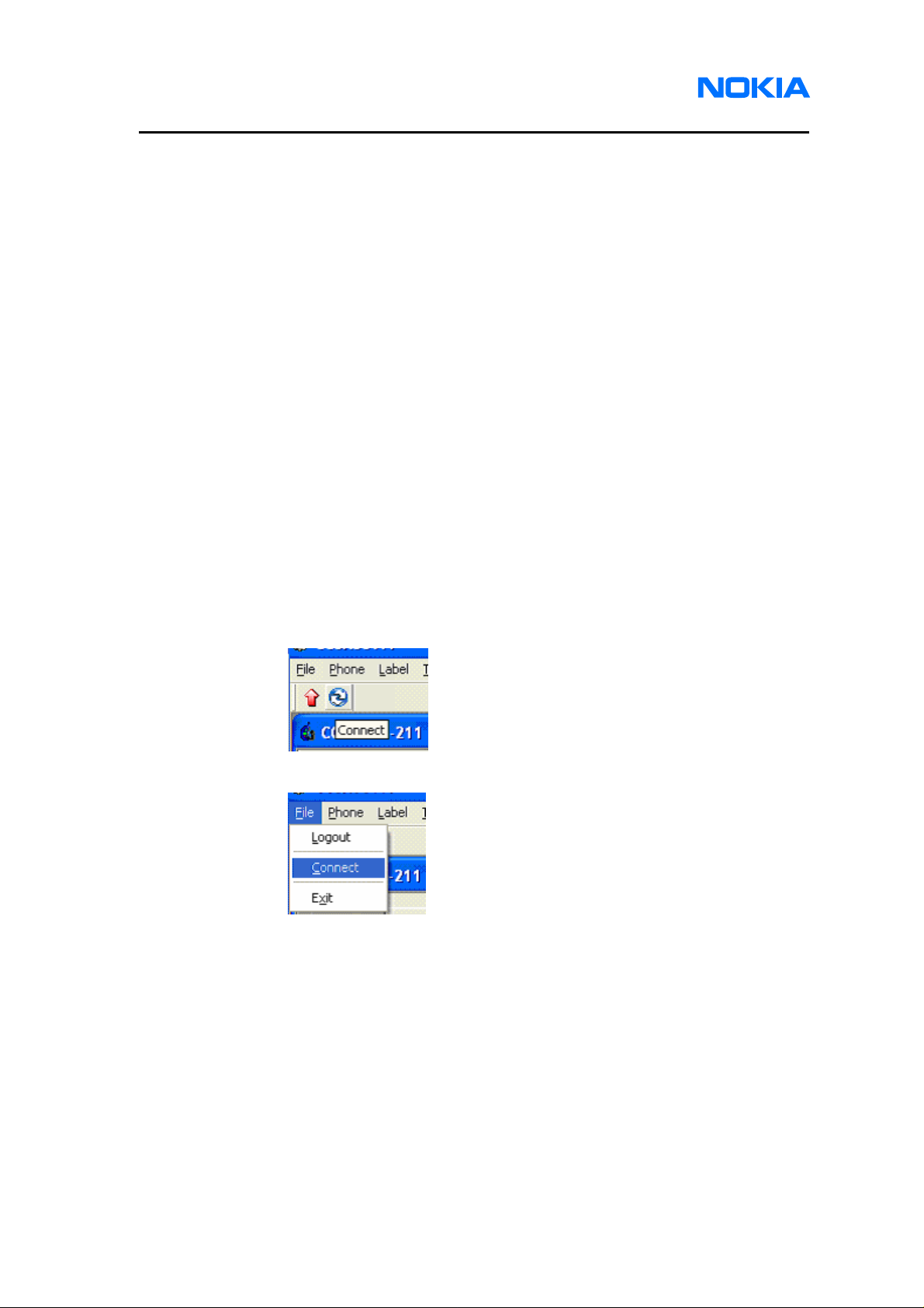
1. Click Connect button on the toolbar as shown in the first figure. Or Open
the File menu, and click Connect as shown in the second figure.
Page 26 © 2007 Nokia Corporation Company Confidential Issue 1 01/2007
Page 27

1255/1265/1315/1325/2505/6066/6088/7088
Nokia Customer Care Service Software Instructions
2. Click Select an active mobile terminal and select one from the list below.
Note that ‘Offline’ means you can use service software functions while the
mobile terminal is not connected, e.g. edit phonebook and data which is
saved in local drive of your service PC or Notebook.
3. In the Connect dialog box, click the OK button.
Using Components
The Service Software tasks are managed by specific software components. Use
the main menu to select the component and functionality you want to make use of. Or
select the tab that is consistent to the main menu. When the new component or
functionality is selected, the Service Software will open an associated dialog with
component-specific UI.
Issue 1 01/2007 © 2007 Nokia Corporation Company Confidential Page 27
Page 28
1255/1265/1315/1325/2505/6066/6088/7088
Service Software Instructions
Login
Login Account
To start using component, level 1 and 2 users have to login by entering a pair of
user name and password by referring to below table, and level 3 users have to plug-in a
specific AMS Software Protection Key to PC or Notebook. The Service Software will
provide appropriate functions according to the log in information. If level 1 and 2 users
want to log in via different username and password, please log out first. We define two
pairs of username and password based on different security levels. See Table 2 for
details.
Service Level User name Password
Level 1 chuck delta
Level 2 captain toctoc
SPC verification
Because many features included in the Service Software need to check service
programming code, there will be another popup dialog for SPC edit purpose after
connection dialog appears. The Service Software will remember this SPC value and help
send SPC request automatically if needed. For phones with Non-RUIM mode, input
correct SPC code to unlock SPC protection. For phones with RUIM mode, just click OK
to unlock SPC protection due to default SPC code is 000000 in RUIM mode. If users
ignore this step, the Service Software will not remember the SPC used in this connection
and SPC protection is enabled.
Use
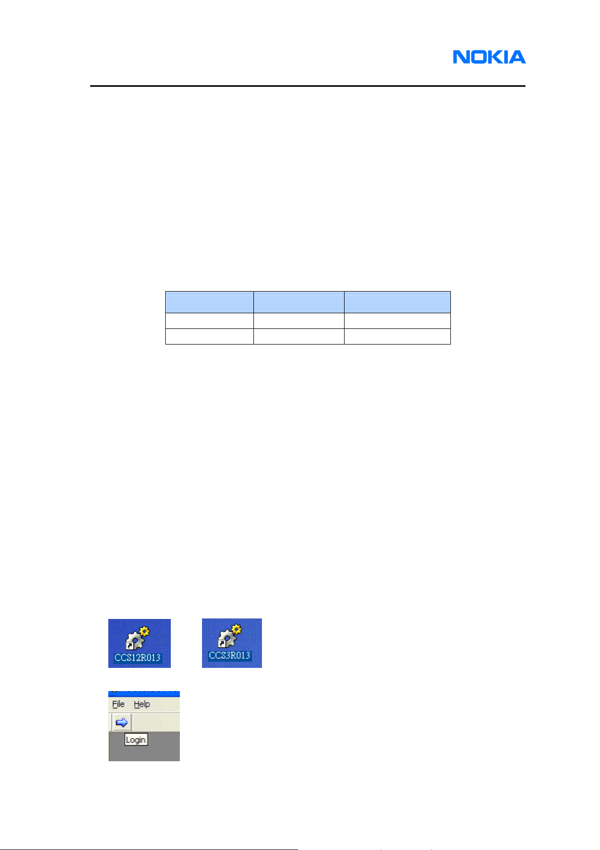
z Three ways to access login screen:
Initiating the Service Software (double click CCS12R013.exe for level 1 and 2
service software; CCS3R013. exe for level 3 service software)
Or
Then, click on login icon
Page 28 © 2007 Nokia Corporation Company Confidential Issue 1 01/2007
Page 29

1255/1265/1315/1325/2505/6066/6088/7088
Nokia Customer Care Service Software Instructions
Or select Login from File menu
z Login screen appears (level 1 and 2 only):
z Two ways to logout:
Click on logout icon.
Issue 1 01/2007 © 2007 Nokia Corporation Company Confidential Page 29
Page 30

1255/1265/1315/1325/2505/6066/6088/7088
Service Software Instructions
Or select Logout from File menu.
z SPC dialog screen appears right after you login. If you click “Ignore” button, certain
functions such as Service Programming, User Data Transfer, Flex Graphics and
Tones will not be available.
Page 30 © 2007 Nokia Corporation Company Confidential Issue 1 01/2007
Page 31

1255/1265/1315/1325/2505/6066/6088/7088
Nokia Customer Care Service Software Instructions
Phone Information
Users can acquire phone information from the selected connections, including:
z Product Code
z PSN
z ESN
z MEID
z SIM ID
z Hardware ID
z Warranty Date
z ESN Date
z RF/Baseband Module Code
z Basic Product Code
z Custom Product Code
z Firmware Version: Boot Code, Application Code, Language Pack and File System
Use
z How to access Phone Info screen:
Click on Phone Info tab.
Or select Phone Info from Phone menu.
Issue 1 01/2007 © 2007 Nokia Corporation Company Confidential Page 31
Page 32

1255/1265/1315/1325/2505/6066/6088/7088
Service Software Instructions
z Phone Info screen:
z Refresh Phone Info screen:
Press Refresh button.
Page 32 © 2007 Nokia Corporation Company Confidential Issue 1 01/2007
Page 33

1255/1265/1315/1325/2505/6066/6088/7088
Nokia Customer Care Service Software Instructions
Flashing
Boot code mode only accesses the flashing feature, which is used for software
upgrade. The Service Software will download the phone image file (*.hex) from PC to the
mobile terminal. Phone images include Boot Code, Application Code, Language Pack
and File System. Users can select the images needed to be upgraded and need not to
download all images every time. The program will prevent users from selecting
erroneous phone images. For example, users cannot feed a language pack image to an
application code image. Users can use the progress bar to check the flashing status and
the completed downloading percentage.
Use
z Two ways to access the Flashing screen:
Click on Flashing tab.
Or select Flashing from the Phone menu.
Issue 1 01/2007 © 2007 Nokia Corporation Company Confidential Page 33
Page 34

1255/1265/1315/1325/2505/6066/6088/7088
Service Software Instructions
z Flashing screen:
z Select image files:
Click the four buttons on the right to browse image file for each feature in your PC.
Page 34 © 2007 Nokia Corporation Company Confidential Issue 1 01/2007
Page 35

1255/1265/1315/1325/2505/6066/6088/7088
Nokia Customer Care Service Software Instructions
z Decide which images needed to be upgraded:
Check (upgrade) or uncheck (no upgrade) the boxes in front of the image texts.
z Select Backup/Restore User data checkbox
z Start to upgrade:
Click Update button.
z Upgrading:
Status bar shows the current status.
z Upgrade succeeded:
Pop up a message box indicating successful upgrade.
Issue 1 01/2007 © 2007 Nokia Corporation Company Confidential Page 35
Page 36

1255/1265/1315/1325/2505/6066/6088/7088
Service Software Instructions
z Flash phones with the same phone type
Support flash phones with the same images.
A message box as below will pop up after successful upgrade.
z Change another phone to connect with PC by transmission line.
z Start to flash another phone by clicking “OK” button and the phone will be upgraded
the same images as the previous phone.
z No need to flash other phones by clicking “Cancel” button.
Page 36 © 2007 Nokia Corporation Company Confidential Issue 1 01/2007
Page 37

1255/1265/1315/1325/2505/6066/6088/7088
Nokia Customer Care Service Software Instructions
Bundle Flashing
This feature is for easy bundle management of flashing file by selecting only one
packed image hex file. After the Service Software recognizing the images included in the
packed file, you can select which part needs to be updated (like Flashing does).
Use
z Two ways to access the Bundle Flashing screen:
Click Bundle Flashing button.
Or select Bundle Flashing from the Phone menu.
z Select the document’s folder in which bundle image exists:
z Select bundle image:
Issue 1 01/2007 © 2007 Nokia Corporation Company Confidential Page 37
Page 38

1255/1265/1315/1325/2505/6066/6088/7088
Service Software Instructions
z Selected bundle file information:
z Select Backup/Restore User data checkbox
z Start to flash:
Click on Update button.
z Continue flashing other phones of the same product type using the same software
images.
A message box as shown below will pop up after successful upgrade.
z Change another phone and use a transmission line to connect the phone with PC.
z Start to flash another phone by clicking on ”OK” button and the phone will be
upgraded with the same images as the previous phone.
z Click ”Cancel” button if there is no need to flash the other phones.
Page 38 © 2007 Nokia Corporation Company Confidential Issue 1 01/2007
Page 39

1255/1265/1315/1325/2505/6066/6088/7088
Nokia Customer Care Service Software Instructions
User data transfer
You do not want to lose user data, such as contact, short message, call register,
organizer records and game setting after the flashing process is done. Users want to
back up data instead of having them replaced or deleted. The Service Software provides
user with data transfer feature that fulfills these requests, i.e. user data backup and
restoration.
Use
z Two ways to access User Data screen:
Click User Data tab.
Or select User Data from the Phone menu.
Issue 1 01/2007 © 2007 Nokia Corporation Company Confidential Page 39
Page 40

1255/1265/1315/1325/2505/6066/6088/7088
Service Software Instructions
z User Data screen appears:
Select user data placement folder path:
Click “…” button on the right of this window to start the folder browser.
z Select backup or restore user data:
z Click “Run” button to perform the action:
Page 40 © 2007 Nokia Corporation Company Confidential Issue 1 01/2007
Page 41

1255/1265/1315/1325/2505/6066/6088/7088
Nokia Customer Care Service Software Instructions
Load Default
This function is used to reformat the user data.
Use
z Two ways to access Load Default screen:
Click on Load Default tab.
Or select Load Default from the Phone menu.
z Load Default screen displays.
Click on “Start” button and then the phone would reset and reformat data
automatically.
Issue 1 01/2007 © 2007 Nokia Corporation Company Confidential Page 41
Page 42

1255/1265/1315/1325/2505/6066/6088/7088
Service Software Instructions
Service Programming
The Service Software provides this function for service programming. With this
feature, users can easily check reading/writing setting data from mobile terminal or files.
There are three tabs – Setting, CDMA1 and CDMA2. We describe each of them in the
following section.
Use
z Two ways to access Service Programming screen:
Click Service Programming tab.
Or select Service Programming from the Phone menu.
z Click on buttons on the bottom to do read/write actions:
Page 42 © 2007 Nokia Corporation Company Confidential Issue 1 01/2007
Page 43

1255/1265/1315/1325/2505/6066/6088/7088
Nokia Customer Care Service Software Instructions
Setting Items
Product part:
Edit Product code – Character string. Maximum length is 15 including digit, alphabet
and sign.
Edit ESN – Number string. Maximum length is 11. (The ESN can be entered only
once. It cannot be rewritten.)
Edit MEID – Number string. Maximum length is 14. (Only 1265, 1325 and 2505 have
MEID item.)
Edit HW ID – Number string. Maximum length is 6.
Edit CPC (Custom Product Code) – Character string. Maximum length is 7.
Codes part:
Edit service programming code (SPC) - Number string. Maximum length is 6.
Edit one time subsidy lock – Number string. Maximum length is 6.
General part:
Choose slot cycle index – value 0 ~ 7
Choose SCM – value 0 ~ 255 (After writing to phone and system reboot, its value will
be reset to default value.)
Issue 1 01/2007 © 2007 Nokia Corporation Company Confidential Page 43
Page 44

1255/1265/1315/1325/2505/6066/6088/7088
Service Software Instructions
Choose current NAM – NAM1 or NAM2
Choose RC Pref – RC1 ~ RC5
Enable/Disable auto NAM
Enable/Disable SPC change enabled
Security part:
Choose mode – RUIM or None RUIM
Page 44 © 2007 Nokia Corporation Company Confidential Issue 1 01/2007
Page 45

1255/1265/1315/1325/2505/6066/6088/7088
Nokia Customer Care Service Software Instructions
CDMA1 Items
NAM Setting:
Choose NAM – NAM1 or NAM2 (This item decides which NAM number of all
CDMA1 setting items needs to be read or written)
Edit NAM name – Character string, maximum length is 15.
Edit dir number – Number string, maximum length is 10.
Edit A-key – Number string, maximum length is 20.
Edit access overload class – Number string, maximum length is 2 (Read-only in
RUIM mode).
Phone number and True IMSI part: (Read-only in RUIM mode)
Enable/Disable class 1.
Edit MCC – Number string, maximum length is 3.
Edit 11_12 – Number string, maximum length is 2.
Edit IMSI_S – Number string, maximum length is 10.
Edit IMSI – Number string, maximum length is 14.
Terminated Registration and Channel part:
Check/uncheck the box to Enable/Disable home SID.
Check/uncheck the box to Enable/Disable foreign SID.
Issue 1 01/2007 © 2007 Nokia Corporation Company Confidential Page 45
Page 46
1255/1265/1315/1325/2505/6066/6088/7088
Service Software Instructions
Check/uncheck the box to Enable/Disable foreign NID.
Edit primary CDMA channel A and B.
Edit secondary CDMA channel A and B.
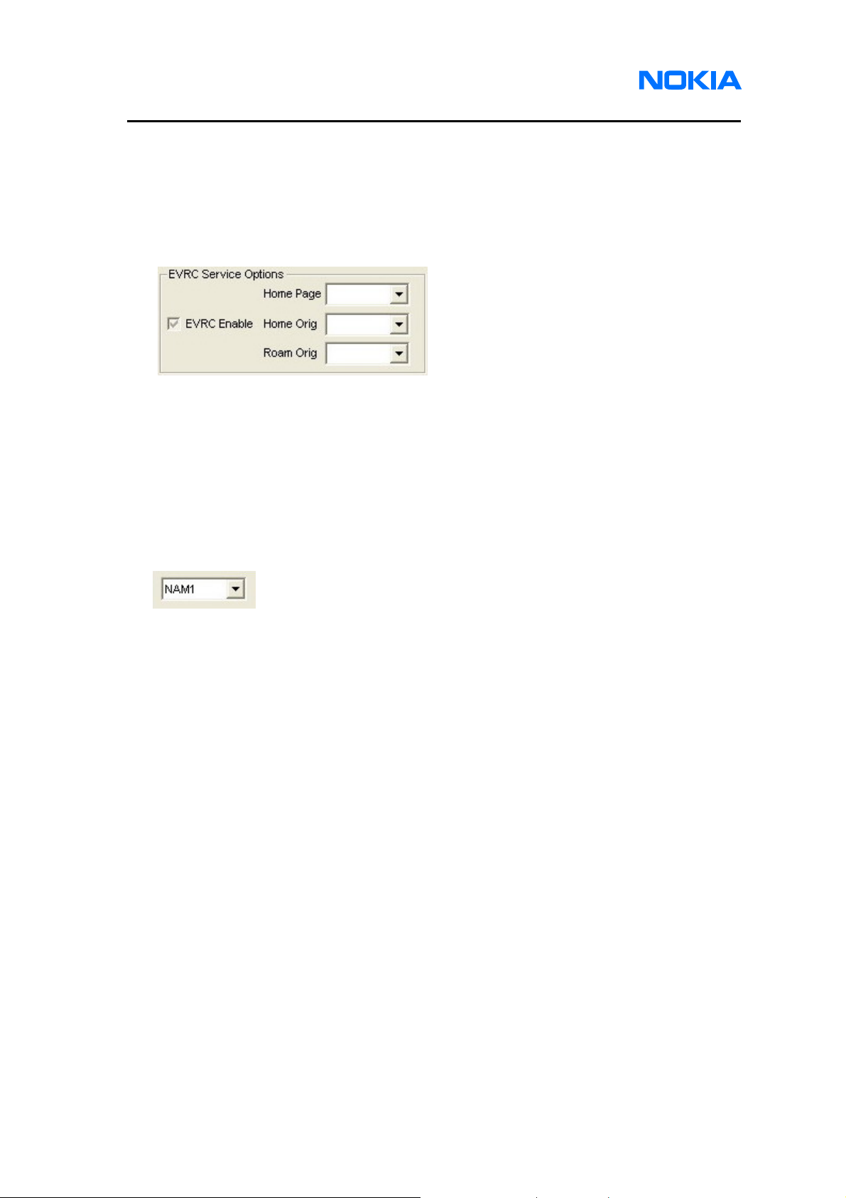
EVRC Service Options part:
Enable/Disable EVRC Enable
Choose home page service option
Choose home origination service option
Choose roam origination service option
CDMA2 Items
NAM Setting:
Choose NAM – NAM1 or NAM2 (This item decides which NAM number of all
CDMA2 setting items needs to be read or written)
Page 46 © 2007 Nokia Corporation Company Confidential Issue 1 01/2007
Page 47

1255/1265/1315/1325/2505/6066/6088/7088
Nokia Customer Care Service Software Instructions
System part:
Edit home SID NID pairs – SID range is from 0 to 32767, NID range is from 0 to
65535.
Choose preferred mode.
Choose band preference.
Choose roam preference.
Preferred roaming part: (Read-only in RUIM mode)
Choose a .PRL file by clicking on “…” button to read or write.
Issue 1 01/2007 © 2007 Nokia Corporation Company Confidential Page 47
Page 48

1255/1265/1315/1325/2505/6066/6088/7088
Service Software Instructions
Flexible graphics and tones
Default graphics and tones files in the mobile terminal could be different in order to
satisfy the different settings and requirements of each country or area. Because the
above files will be changed to accommodate to different settings during manufacture,
they need to be designed for easy and dynamic configuration. The Service Software
provides flexible graphics and tones features such as default data writing, that are able
to satisfy these requirements. Users can easily drag and drop directories and files
between the mobile terminal’s default directory and the PC file system. Furthermore, it
can create a directory or delete files and directories in the mobile terminal. To avoid file
crashed during transferring, the phone will be set to offline mode and MUST power cycle
for using call services.
Use
z Two ways to access the Flexible Graphics/Tones screen:
Click Flex Graphics/Tones tab.
Or select Flex Graphics/Tones from the Phone menu.
Page 48 © 2007 Nokia Corporation Company Confidential Issue 1 01/2007
Page 49

1255/1265/1315/1325/2505/6066/6088/7088
Nokia Customer Care Service Software Instructions
z Flex Graphics/Tones screen shows:
z Copy files from the mobile terminal to the PC
Press and hold the mouse’s left button on either of the directories or files at the
right window, e.g. “brew” directory. And move the mouse to the disk or directory that
you want the copy data to be stored at the left window, e.g. D:\. Then release the
mouse’s left button and it will start copying files from the mobile terminal to the PC.
Issue 1 01/2007 © 2007 Nokia Corporation Company Confidential Page 49
Page 50

1255/1265/1315/1325/2505/6066/6088/7088
Service Software Instructions
z Copy files from PC to Phone.
Press and hold the mouse’s left button on either the directories or files at the left
window, e.g. C:\ frames directory. And move the mouse to some directory at the right
window, e.g. brew\user\ga. Then release mouse left button will start copying files
from PC to phone.
Page 50 © 2007 Nokia Corporation Company Confidential Issue 1 01/2007
Page 51

1255/1265/1315/1325/2505/6066/6088/7088
Nokia Customer Care Service Software Instructions
z Create a directory in the mobile terminal:
Select one directory from the mobile terminal, and press mouse’s right button. Then
select New Directory.
Enter a name for the new directory. When done, click OK.
z Delete a directory or a file from the mobile terminal:
Select a directory or file in mobile terminal, and press mouse’s right button. Then
select Delete to start deleting.
Issue 1 01/2007 © 2007 Nokia Corporation Company Confidential Page 51
Page 52

1255/1265/1315/1325/2505/6066/6088/7088
Service Software Instructions
SID
This feature is for 50 SID lock numbers edit, with the value ranging from 0 to 65535.
Users can read and write from mobile terminal or file. If user chooses “Write to File”, the
file content is encrypted.
Use
z Two ways to access the SID screen:
Click SID tab.
Or select SID from the Phone menu.
z Check/Uncheck the box to Enable/Disable SID Lock:
z Edit SID lock number:
Page 52 © 2007 Nokia Corporation Company Confidential Issue 1 01/2007
Page 53

1255/1265/1315/1325/2505/6066/6088/7088
Nokia Customer Care Service Software Instructions
z Click on buttons in the bottom to perform read/write actions:
Issue 1 01/2007 © 2007 Nokia Corporation Company Confidential Page 53
Page 54
1255/1265/1315/1325/2505/6066/6088/7088
Service Software Instructions
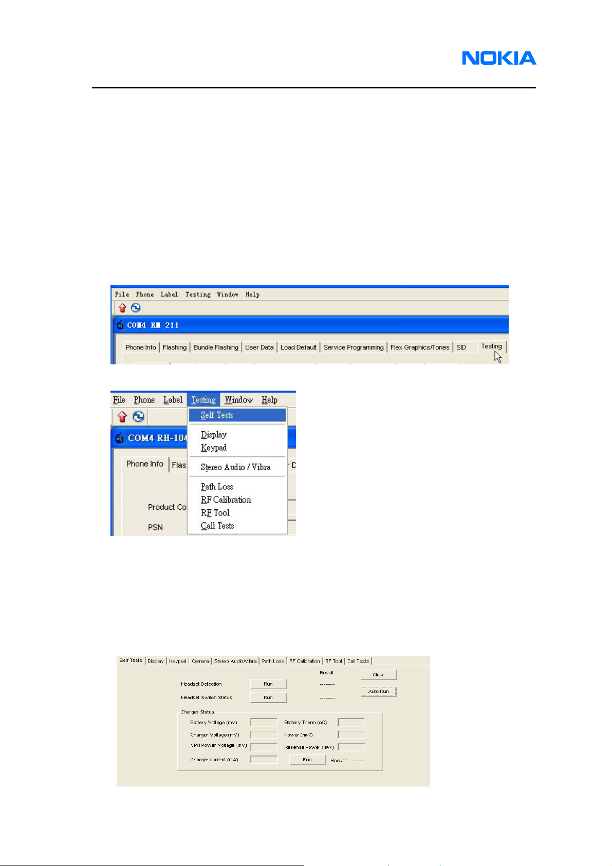
Testing
This feature is for checking and diagnosing the basic function of mobile terminal. It’s
useful to quickly find out which part of the mobile terminal functions normal or abnormally.
There are six tabs – Self Tests, Display, Keypad, Stereo Audio/Vibra, RF Calibration and
RF Tool. We describe each of them in the following section.
Use
z Two ways to access the Testing screen:
Click Testing tab.
Or select Testing from the menu.
Self Tests
Test items: Headset Detection, Headset Switch Status and Charger Status.
• Click each “Run” button to test each item.
• Click “Clear” button to clear all test result.
• Click “Auto Run” button to run all items
.
Page 54 © 2007 Nokia Corporation Company Confidential Issue 1 01/2007
Page 55

1255/1265/1315/1325/2505/6066/6088/7088
Nokia Customer Care Service Software Instructions
Display
Test screen pixels (Fill LCD total screen) – check if full screen is filled with black
color.
Test backlight – check if backlight turns on.
Test brightness – check if brightness can be set to low level and high level
Test color display – check if colors could display on LCD.
Keypad
Test keypad – check if each key has pressed down and CCS will display its keypad
according to its phone model. The following are snapshots of 1255/1315, 1265/1325,
6066/6088/7088, 2505 respectively.
1255/1315 Keypad testing snapshot
Issue 1 01/2007 © 2007 Nokia Corporation Company Confidential Page 55
Page 56

1255/1265/1315/1325/2505/6066/6088/7088
Service Software Instructions
1265/1325 Keypad testing snapshot
6066/6088/7088 Keypad testing snapshot
2505 Keypad testing snapshot
Page 56 © 2007 Nokia Corporation Company Confidential Issue 1 01/2007
Page 57

1255/1265/1315/1325/2505/6066/6088/7088
Nokia Customer Care Service Software Instructions
Keypad emulation – If press any button on the right hand side, the phone will act as
the text shown like “Press Key 7 Down”.
Camera
The function is only for 6066, 6088 and 7088.
Test Preview on – check if the Preview is showed on the main LCD
Test Preview Off – check if the Preview is closed.
Test Flash light – check if the light flashes on.
Test Camera Capture – check if the camera can capture the photo that shown on
the main LCD.
Stereo Audio/Vibrator
Test speaker – check if speaker plays the power-on sound.
Test receiver (earpiece) – talk to microphone and check if echo
voice can be received from receiver (earpiece).
Test headset – talk to microphone and check if echo voice can be received from
headset.
Test vibrator – check if vibrator turns on.
Test microphone – there are three test items –
1. Talk to microphone and check if echo voice can be received from speaker.
2. Talk to microphone and check if echo voice can be received from receiver
(earpiece).
3. Talk to microphone and check if echo voice can be received from headset.
Test Buzzer/IHF’s - there are two test items –
1. Speaker sound beeps twice, one is low frequency level and the other is high
frequency level.
2. Speaker sound beeps twice, one is low volume level and the other is high
Issue 1 01/2007 © 2007 Nokia Corporation Company Confidential Page 57
Page 58

1255/1265/1315/1325/2505/6066/6088/7088
Service Software Instructions
volume level.
Test Mic Bias – there are two test cases –
1. Microphone on. Talk to microphone and check if echo voice can be received
from speaker.
2. Microphone off. Talk to microphone and check if echo voice is turned off.
Test Tx Gain – there are two test items –
1. Adjust tx gain to low level. Talk to microphone and check if echo voice with
low volume is received from speaker.
2. Adjust tx gain to high level. Talk to microphone and check if echo voice with
large volume received from speaker.
Test Rx Gain – there are two test items –
1. Adjust rx gain to low level. Talk to microphone and check if echo voice with
low volume is received from speaker.
2. Adjust rx gain to high level. Talk to microphone and check if echo voice with
large volume is received from speaker.
Test IHF – there are two test items –
1. IHF on. Check if speaker sounds the power-on sound.
2. IHF off. Check if speaker stops sounding the power-on sound.
Test Speaker audio amplifier – there are three test items –
1. Speaker audio amplifier on. Check if speaker sounds the power-on sound.
2. Speaker audio amplifier off. Check if speaker stops sounding the power-on
sound.
3. Speaker audio amplifier on. Check if speaker sounds the remaining
power-on sound.
Page 58 © 2007 Nokia Corporation Company Confidential Issue 1 01/2007
Page 59

1255/1265/1315/1325/2505/6066/6088/7088
Nokia Customer Care Service Software Instructions
Path Loss
Path Loss is a tool for automatically calibrating the RF path loss between a handset
and the call box.
z Access the Path Loss screen:
Click on the button of Enter Path Loss on the middle of the windows.
Path Loss screen:
Input the maximum output power of the golden phone in dBm. For 1255 and 1315,
input maximum output power as 24 dBm. For 6066, input 24.2 dBm. For 6088 and
7088, input 24.5 dBm. For 1265, 1325 and 2505, input ??? dBm. Click “Start” button
to run program.
After the program is done, the path loss will be shown on the screen and recorded
for the RF calibration and Call Test program. Click “Quit” to close this program.
Issue 1 01/2007 © 2007 Nokia Corporation Company Confidential Page 59
Page 60

1255/1265/1315/1325/2505/6066/6088/7088
Service Software Instructions
RF Calibration
RF calibration is a tool for automatically tuning the RF values of target.
z How to access the RF Calibration screen:
Click on the middle button of RF Calibration tab.
Page 60 © 2007 Nokia Corporation Company Confidential Issue 1 01/2007
Page 61

1255/1265/1315/1325/2505/6066/6088/7088
Nokia Customer Care Service Software Instructions
z RF Calibration screen:
Set Loss and click “Start” button to run program.
Click “Save” to save the log to a text file, then click “Quit” to close this program.
z Error Message Table
Error Message Upper Limit Lower Limit Debug
FAIL:TESTER Check your GPIB connection.
FAIL:COMPORT Check your COM connection.
FAIL:DVGA 3000 1700 Possible reason:
Default NV table could be
wrong.
File system does not exist.
Image version inconsistent.
FAIL:LNA0 150 100 Check Rx path components
FAIL:LNA1 250 150 Check Rx path components
FAIL:LNA2 410 300 Check Rx path components
FAIL:LNA3 560 430 Check Rx path components
FAIL:LOW_GAIN 25 dBm 5 dBm Synthesizer unlock
FAIL:HIGH_GAIN 27 dBm 5 dBm Synthesizer unlock
FAIL:HDET 210 120 Check Rx/Tx path components
Issue 1 01/2007 © 2007 Nokia Corporation Company Confidential Page 61
Page 62

1255/1265/1315/1325/2505/6066/6088/7088
Service Software Instructions
RF Tool
RF tool allows users to check some RF values for diagnosing.
z Access the RF Tool screen:
Click on the middle button of RF Tool tab.
Page 62 © 2007 Nokia Corporation Company Confidential Issue 1 01/2007
Page 63

1255/1265/1315/1325/2505/6066/6088/7088
Nokia Customer Care Service Software Instructions
z RF T ool screen:
Please check from up-to-down and left-to-right direction for each item.
Click to connect mobile terminal.
Issue 1 01/2007 © 2007 Nokia Corporation Company Confidential Page 63
Before clicking this button, make sure you boot the CDMA phone with
“Test Mode” (The battery ID pin is connected to a resistor (< 10k
Ohm). The other end of the resistor is connected to the ground. ) and
connect the COM cable correctly.
Page 64

1255/1265/1315/1325/2505/6066/6088/7088
Service Software Instructions
After clicking this button, if the COM connection is
successful, this button becomes dimmed.
Page 64 © 2007 Nokia Corporation Company Confidential Issue 1 01/2007
Always skip this function, since your CDMA
phone’s battery ID pin is connected to a resistor
(<10k Ohm). The other end of the resistor is
connected to the ground.
Page 65

1255/1265/1315/1325/2505/6066/6088/7088
Nokia Customer Care Service Software Instructions
Click the functions according to the order of number to verify the performance of the
CDMA phone.
3 4
10
11
5
1
2
6
12
13
7
14
8
9
1. Set the RF Band of the CDMA phone.
2. Set the Transmitter/Receiver channel.
3. Read the ADC value of the selected channel.
4. Set the waveform generated by transmitter.
5. Set the dynamic range of the Power Amplifier. Set “OFF” to have low gain range.
Set “ON” to have high gain range.
6. Set “OFF” to turn off the transmitter output power. Set “ON” to turn on the
Issue 1 01/2007 © 2007 Nokia Corporation Company Confidential Page 65
Page 66

1255/1265/1315/1325/2505/6066/6088/7088
Service Software Instructions
transmitter power.
7. Set the Tx AGC value within the range 0~511. The value 511 means that the
transmitter generates the minimum output power. 0 means the transmitter
generates the maximum output power.
8. Set “ON” to have the transmitter sweep the output power.
9. Read the HDET value of selected channel.
10. Set the LNA range.
11. Read the DVGA value while LNA Range is 0.
12. Set the DVGA offset with the value derived after running step 11.
13. Read the LNA Offset value.
14. Read IM2 value.
The “Set Online” function is no longer needed since the “Test Mode” and “Online mode”
is no longer switched manually. The mode will be switched on by connecting the Battery
ID pin to the resistor of different values.
Test Mode : Battery ID Pin Æ Resistor (4K<R<10K Ohm) Æ Ground
Online Mode : Battery ID Pin Æ Resistor (10K<R<140K Ohm) Æ Ground
Page 66 © 2007 Nokia Corporation Company Confidential Issue 1 01/2007
Page 67

1255/1265/1315/1325/2505/6066/6088/7088
Nokia Customer Care Service Software Instructions
Call Test
Setup:
Connect your PC and Agilent 8960 with GPIB cable.
Connect your CDMA phone and the Agilent 8960 with the CA-89RS RF Test cable.
z Access the Call Test screen:
Click on the button of Enter Call Tests on the middle of the window.
z Call T est screen:
Click “Start” to perform the test.
Issue 1 01/2007 © 2007 Nokia Corporation Company Confidential Page 67
Page 68

1255/1265/1315/1325/2505/6066/6088/7088
Service Software Instructions
Click “Save” to save the log to a text file, then click “Quit” to close this program.
z Error Message Table
Error Message Upper Limit Lower Limit Debug
FAIL:MAX POWER 25 23 Make sure the RF cable loss is
correct.
FAIL:FER CONF 0 ----------------- Configure the count to zero.
FAIL:FER 0.5 ----------------- Channel interference occurred.
Shielding box should be used in
this test.
FAIL:WAVQ RHO 0.985 ----------------- Check Rx/Tx path components
FAIL:WAVQ FREQ 150 Hz -150 Hz Check Rx/Tx path components
"FAIL:WAVQ TIME 1 us -1 us Check Rx/Tx path components
FAIL:ACPR -885 -44 ----------------- Check Rx/Tx path components
FAIL:ACPR +885 -44 ----------------- Check Rx/Tx path components
FAIL:ACPR -1980 -56 ----------------- Check Rx/Tx path components
FAIL:ACPR +1980 -56 ----------------- Check Rx/Tx path components
Page 68 © 2007 Nokia Corporation Company Confidential Issue 1 01/2007
Page 69

1255/1265/1315/1325/2505/6066/6088/7088
Nokia Customer Care Service Software Instructions
Memory Capture
This tool provides a simple way to dump whole memory from phone to service PC,
service people can send this file to R&D team for further failure analysis immediately to
make software related issue to be analyzed more efficient. To dump memory helps R&D
team to resolve and analyze software related issues, not suitable for hardware or
components issues.
Use
z Access the MEM Capture screen:
Click MEM Capture tab.
z Browse to destination folder and give a file name
Click “…” button on the right of this window to start the folder browser. Browse to a
destination folder and give a file name. Extension name for this file set to .bin as
default.
z Start to capture memory into a file
It’s not necessary to input any value into “Start Address” and “Length (byte)” field,
service software will set it to appropriate number on the basis of which phone model
is connected. Click Read from Phone button.
Issue 1 01/2007 © 2007 Nokia Corporation Company Confidential Page 69
Page 70

1255/1265/1315/1325/2505/6066/6088/7088
Service Software Instructions
Label Printing
This tool provides a preview for label printing. Users can make sure its label layout
by setting offset for x-axis or y-axis, and choose printers before printing. Note that all
label layouts are based on 600-dpi resolution, so printer driver should adjust to 600-dpi
for an appropriate label size.
Use
z Access the Label Printing screen:
Select Label Printing from the Label menu.
z Label Printing screen:
z Setting offset for x-axis and y-axis position (base on 600-dpi):
z Choose label type (country):
z Choose printer name:
Page 70 © 2007 Nokia Corporation Company Confidential Issue 1 01/2007
Page 71

1255/1265/1315/1325/2505/6066/6088/7088
Nokia Customer Care Service Software Instructions
z Support label-printing by different phones with the same label type. Get different data
by changing transmission line and clicking the following button
z Data from phone like ESN Hex will be shown on the dialog.
z Display real file to be printed.
z Click “Print” button to start printing the label showing on the dialog and the x and y
axis will be recorded:
Issue 1 01/2007 © 2007 Nokia Corporation Company Confidential Page 71
Page 72

1255/1265/1315/1325/2505/6066/6088/7088
Service Software Instructions
Appendix A. Procedure of reviving a dead phone
The Service Software provides a simple way for reviving a dead phone. Note that a
dead phone here refers to a phone that cannot power on normally. And if the boot code
is not crashed, we can follow this procedure to re-flash phone images. This procedure
can only revive a phone that is crashed in terms of software issues.
1. Run the Service Software and log in.
2. Press ‘ * ‘, ‘ 5 ’ and ‘ Power key ‘ simultaneously to enter bootloader download
mode.
3. It should show entering bootloader download mode for the connected phone.
4. Click “OK” and then “Bundle Flashing” tab shows as below.
5. Choose bundle file path for flashing.
Page 72 © 2007 Nokia Corporation Company Confidential Issue 1 01/2007
Page 73

1255/1265/1315/1325/2505/6066/6088/7088
Nokia Customer Care Service Software Instructions
6. Click “Update” to start re-flashing.
7. There is another way to perform reflashing by selecting individual files of phone
image, e.g. Application code, Language Pack and File System. Select individual
files through “Flashing” function as shown below, then click “Update” to start
re-flashing.
Issue 1 01/2007 © 2007 Nokia Corporation Company Confidential Page 73
Page 74

1255/1265/1315/1325/2505/6066/6088/7088
Service Software Instructions
Appendix B. Procedure of multi-flashing Part I
The Service Software supports the flashing of multiple phones at the same time. This
functionality will be very convenient when larger quantities of phones have to be
upgraded. Please follow the steps as described below.
1. Prepare a USB hub and ensure all phones are connected to the USB hub.
2. Run the Service Software and log in.
3. It should show all connected phones, COM5 and COM7.
4. Select COM5 and click OK.
5. Press “Connect” icon and it should show other remaining connected phone, e.g.
COM7.
Page 74 © 2007 Nokia Corporation Company Confidential Issue 1 01/2007
Page 75

1255/1265/1315/1325/2505/6066/6088/7088
Nokia Customer Care Service Software Instructions
6. Select COM7 and click OK.
7. Then, you can flash each connected phone at the same time just like you flash
one phone. Please refer to Flashing and Bundle Flashing section for detailed
flashing instructions.
Issue 1 01/2007 © 2007 Nokia Corporation Company Confidential Page 75
Page 76

1255/1265/1315/1325/2505/6066/6088/7088
Service Software Instructions
Appendix C. Procedure of multi-flashing Part II
The Service Software supports multi-flashing for mass firmware upgrade at the same
time. This functionality will be very convenient when large quantities of phones need to
be upgraded. Following are the steps of using service software multi-flashing function.
1. Remove all Data Service Cables between USB hub and phones.
2. Launch service software. Check Select multi-flash and click on “OK“ button to
activate multi-flashing function with no phone connection.
Page 76 © 2007 Nokia Corporation Company Confidential Issue 1 01/2007
Page 77

1255/1265/1315/1325/2505/6066/6088/7088
Nokia Customer Care Service Software Instructions
3. Connect all phones to USB hub and make sure all phones with charger.
4. Check device manager to make sure the phones are detected with the same
driver and work normally.
5. Set specific COM port number to avoid abnormal situation like COM port
changed after boot up phone.
Issue 1 01/2007 © 2007 Nokia Corporation Company Confidential Page 77
Page 78

1255/1265/1315/1325/2505/6066/6088/7088
Service Software Instructions
Page 78 © 2007 Nokia Corporation Company Confidential Issue 1 01/2007
Page 79

1255/1265/1315/1325/2505/6066/6088/7088
Nokia Customer Care Service Software Instructions
If your phone is Bambi/Thumper/Flower, please set specific COM port number to
each phone modem and the step is as following.
Issue 1 01/2007 © 2007 Nokia Corporation Company Confidential Page 79
Page 80

1255/1265/1315/1325/2505/6066/6088/7088
Service Software Instructions
6. Remove the USB hub from PC and plug in again
7. Check if the COM port is the same as previous setting. If yes, go to next step.
Otherwise, check COM port setting is correct or not.
8. Start flashing by choosing images. Mutli-flashing support bundle image and
normal images downloaded by checking on below buttons.
8.1 If you select , please choose the bundle file (*.nfp, *.cbb) for the
phone as following.
8.2 If you select , please choose images as following.
Page 80 © 2007 Nokia Corporation Company Confidential Issue 1 01/2007
Page 81

1255/1265/1315/1325/2505/6066/6088/7088
Nokia Customer Care Service Software Instructions
9. Service software multi-flashing function supports auto-detect phone by checking
“Auto” radio button and manual-connect phone by checking “Manual” radio
button.
10. The mobile terminal with the COM port you checked will be start to flashing by
clicking “Flash” button.
11. You can click to choose all COM ports (8 ports) or select each COM
port one by one.
11.1 As below picture shown, COM5, COM6, COM7 and COM8 will be
flashed.
Issue 1 01/2007 © 2007 Nokia Corporation Company Confidential Page 81
Page 82

1255/1265/1315/1325/2505/6066/6088/7088
Service Software Instructions
12. After flashing is completed, the check boxs will not be unchecked for next
flashing and progress bar will display “Download Image Successfully” as below.
Note that it is forbidden that remove the successful flashed phone while any
other phone is still under flashing.
Page 82 © 2007 Nokia Corporation Company Confidential Issue 1 01/2007
Page 83

1255/1265/1315/1325/2505/6066/6088/7088
Nokia Customer Care Service Software Instructions
13. To finish flashing, you can click ”Exit” button to exit the program.
To keep flashing for other phones, go to step 8.
Issue 1 01/2007 © 2007 Nokia Corporation Company Confidential Page 83
Page 84

1255/1265/1315/1325/2505/6066/6088/7088
Service Software Instructions
This page intentionally left blank.
Page 84 © 2007 Nokia Corporation Company Confidential Issue 1 01/2007
 Loading...