

Nokia 108 x
Service Manual for L1 andL
2
z
z
z
z
Nokia 108,
Nokia 108 DS
RM-944, RM-945
Check the repair
policy before
Key features
1.8" QQVGA Display
MicroSD memory card support up to 32GB
VGA Camera
Torch light
Version 1.0
performing any
mechanical repair
on Service Level
1&2!
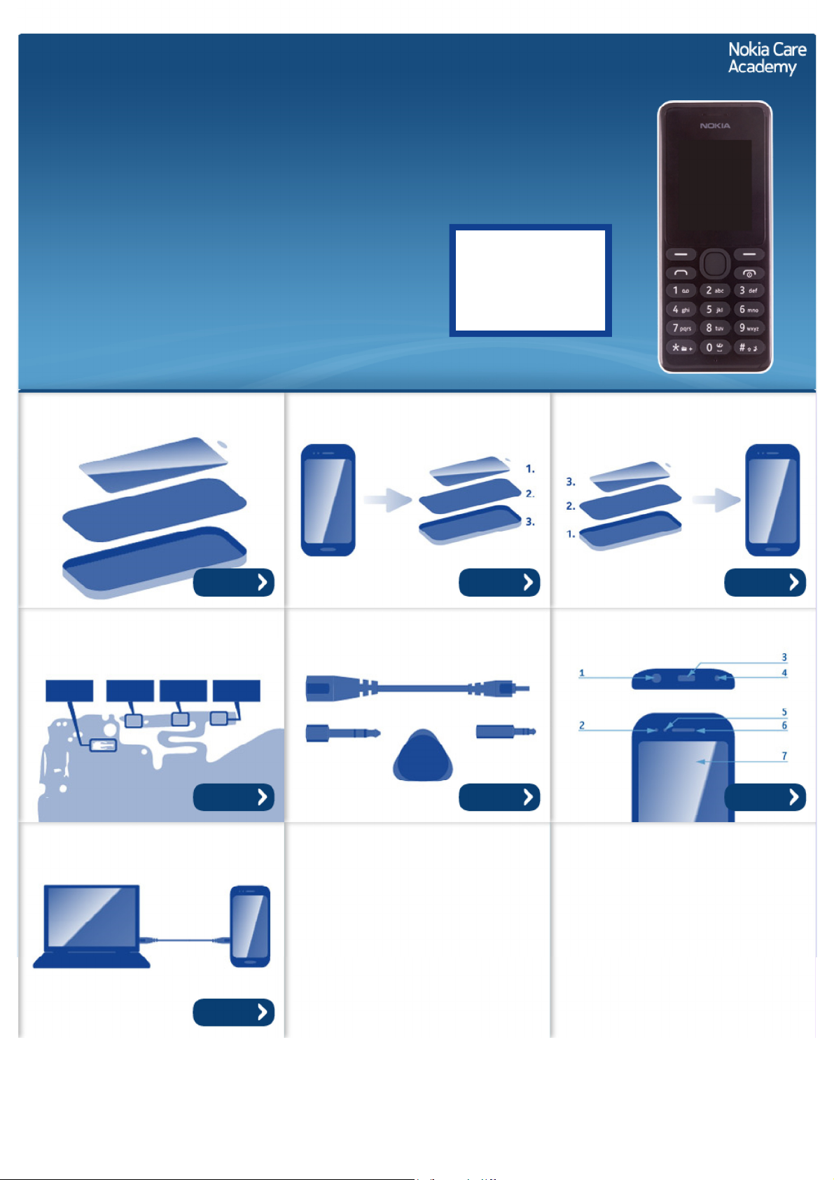
Exploded view Disassembly steps Assembly hints
More More More
Solder components Service devices Product controls and interfaces
Service concept
More More More
More
©2013 Nokia | Nokia Internal Use only | All Rights Reserved.

Service Manual Level 1 and 2
Nokia 108, 108 Dual SIM
RM-944, RM-945
Version 1.0
A-COVER
I0001
LIGHTGUIDE FRAME ASSEMBLY
(I0003 - I0005)
1
Exploded view
KEYMAT
I0002
UI SHIELDING
I0003
EARPIECE ADHESIVE
LIGHT SWAP PACKAGE
(I0006 - I0010)
2
LIGHT SWAP PWB
D-COVER ASSEMBLY
(I0012 - I0015)
3
I0005
EARPIECE
I0004
I0006
CAMERA
I0011
AV JACK
I0012
DC JACK
I0013
DOMESHEET
I0007
FEM SHIELDING LID
I0009
BB SHIELDING LID
I0008
SPEAKER
I0014
SPEAKER GASKET
I0015
TYPE LABEL
I0010
SCREW TORX+ SIZE 4
M1.4 x 4.5
I0016
Only available
as assembly
©2013 Nokia | Nokia Internal Use only | All Rights Reserved.
B-COVER
I0017
Not reuseable
after removal
Repair/swap
only in level 3
Service Manual Level 1 and 2
Nokia 108, 108 Dual SIM
RM- 944, RM-945
Version 1.0
Disassembly steps
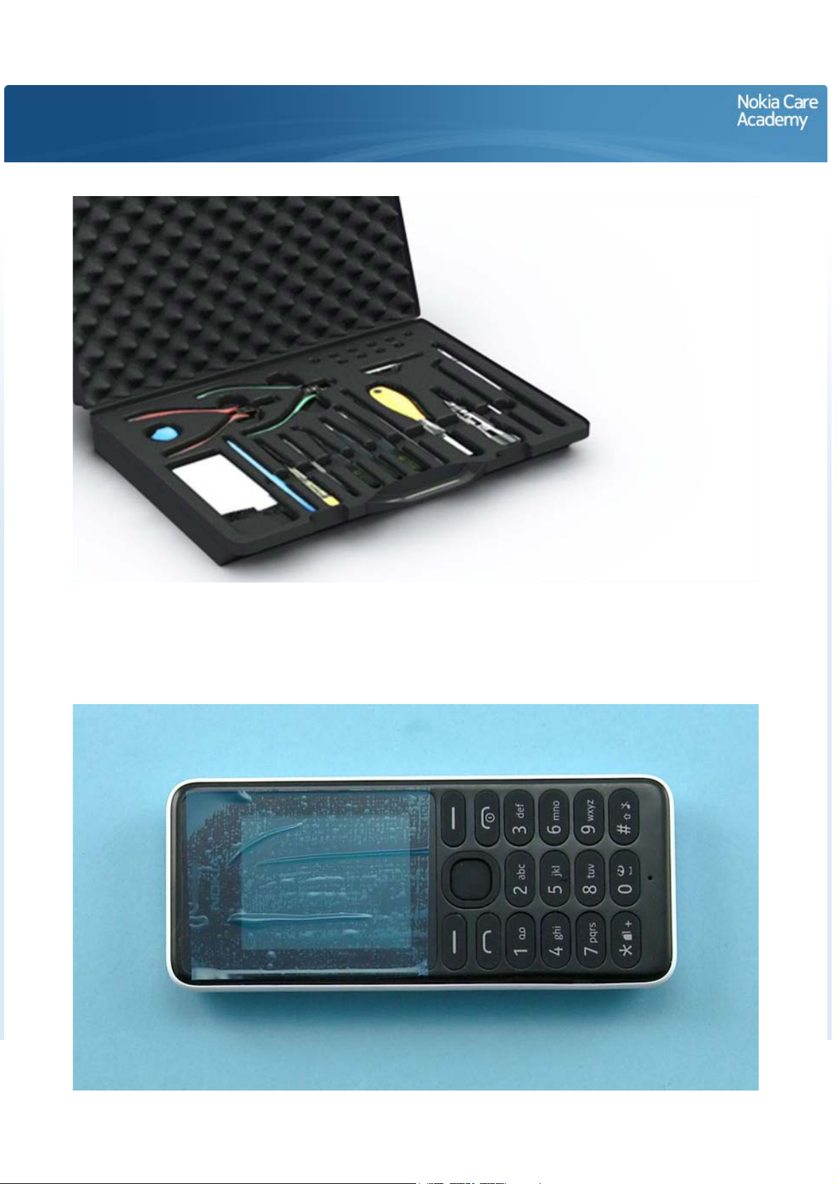
1) For disassembling you need the Nokia Standard toolkit version 2.
Note that the device used in this disassembly procedure is the dual SIM variant, RM-944. All the
disassembly steps are the same for both single and dual SIM variants.
2) Protect the A-COVER window with protective film.

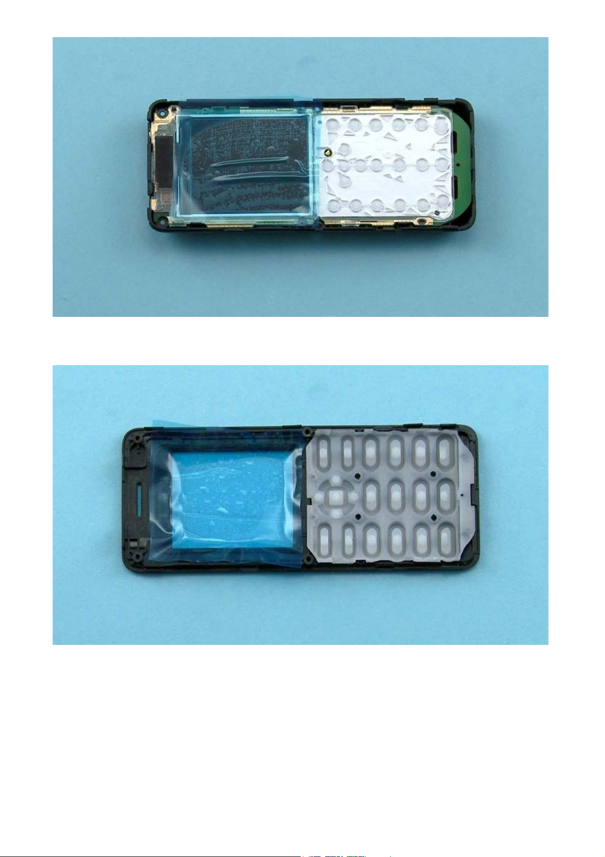
3) To detach the B-COVER press the CAMERA BEZEL and then pull the B-COVER with fingers. Remove the
B-COVER.
4) If there is a BATTTERY remove it also.

5) Unscrew the four Torx+ size 4 screws in the order shown.
6) To rseparate the D-COVER and the A-COVER, first release the shown clips on the right side with the
SRT-6.

7) Use the SRT-6 to release the clips on the bottom side.
8) Then release the clips from the left side of the device.

9) Lift the bottom end of the A-COVER and release the clips on the top side.
10) The D-COVER and the A-COVER can now be separated.
11) Protect the DISPLAY with protective film.
12) Protect the other side of the A-COVER window with protective film.
 Loading...