

Page 1

Nokia100i
Installation Guide
Part No. N451654001 Rev A
Published June 2005
Page 2

COPYRIGHT
©2005 Nokia. All rights reserved.
Rights reserved under the copyright laws of the United States.
RESTRICTED RIGHTS LEGEND
Use, duplication, or disclosure by the United States Government is subject to restrictions as set
forth in subparagraph (c)(1)(ii) of the Rights in Technical Data and Computer Software clause at
DFARS 252.227-7013.
Notwithstanding any other license agreement that may pertain to, or accompany the delivery of,
this computer software, the rights of the United States Government regarding its use,
reproduction, and disclosure are as set forth in the Commercial Computer Software-Restricted
Rights clause at FAR 52.227-19.
IMPORTANT NOTE TO USERS
This software and hardware is provided by Nokia Inc. as is and any express or implied
warranties, including, but not limited to, implied warranties of merchantability and fitness for a
particular purpose are disclaimed. In no event shall Nokia, or its affiliates, subsidiaries or
suppliers be liable for any direct, indirect, incidental, special, exemplary, or consequential
damages (including, but not limited to, procurement of substitute goods or services; loss of use,
data, or profits; or business interruption) however caused and on any theory of liability, whether in
contract, strict liability, or tort (including negligence or otherwise) arising in any way out of the use
of this software, even if advised of the possibility of such damage.
Nokia reserves the right to make changes without further notice to any products herein.
TRADEMARKS
Nokia is a registered trademark of Nokia Corporation. Other products mentioned in this
document are trademarks or registered trademarks of their respective holders.
050110
2 Nokia 100i Installation Guide
Page 3

Nokia Contact Information
Corporate Headquarters
Web Site http://www.nokia.com
Telephone 1-888-477-4566 or
1-650-625-2000
Fax 1-650-691-2170
Mail
Address
Regional Contact Information
Americas Nokia Inc.
Europe,
Middle East,
and Africa
Asia-Pacific 438B Alexandra Road
Nokia Customer Support
Web Site: https://support.nokia.com/
Email: tac.support@nokia.com
Nokia Inc.
313 Fairchild Drive
Mountain View, California
94043-2215 USA
313 Fairchild Drive
Mountain View, CA 94043-2215
USA
Nokia House, Summit Avenue
Southwood, Farnborough
Hampshire GU14 ONG UK
#07-00 Alexandra Technopark
Singapore 119968
Tel: 1-877-997-9199
Outside USA and Canada: +1 512-437-7089
email: info.ipnetworking_americas@nokia.com
Tel: UK: +44 161 601 8908
Tel: France: +33 170 708 166
email: info.ipnetworking_emea@nokia.com
Tel: +65 6588 3364
email: info.ipnetworking_apac@nokia.com
Americas Europe
Voice: 1-888-361-5030 or
Fax: 1-613-271-8782 Fax: +44 (0) 125-286-5666
Asia-Pacific
Voice: +65-67232999
Fax: +65-67232897
Nokia 100i Installation Guide 3
Voice: +44 (0) 125-286-8900
1-613-271-6721
050602
Page 4

4 Nokia 100i Installation Guide
Page 5

Contents
About this Guide . . . . . . . . . . . . . . . . . . . . . . . . . . . . . . . . . . . . . . .9
In This Guide . . . . . . . . . . . . . . . . . . . . . . . . . . . . . . . . . . . . . . . . . . 9
Conventions This Guide Uses . . . . . . . . . . . . . . . . . . . . . . . . . . . . 10
Notices . . . . . . . . . . . . . . . . . . . . . . . . . . . . . . . . . . . . . . . . . . . . 10
Command-Line Conventions. . . . . . . . . . . . . . . . . . . . . . . . . . . . 11
Text Conventions . . . . . . . . . . . . . . . . . . . . . . . . . . . . . . . . . . . . 13
Related Documentation . . . . . . . . . . . . . . . . . . . . . . . . . . . . . . . . . 14
1 Overview . . . . . . . . . . . . . . . . . . . . . . . . . . . . . . . . . . . . . . . . . . . 15
About the Nokia 100i Gateway. . . . . . . . . . . . . . . . . . . . . . . . . . . . 15
Memory . . . . . . . . . . . . . . . . . . . . . . . . . . . . . . . . . . . . . . . . . . . . 15
Encryption Acceleration. . . . . . . . . . . . . . . . . . . . . . . . . . . . . . . . 16
Nokia 100i Gateway Overview. . . . . . . . . . . . . . . . . . . . . . . . . . . . 16
Preparing the Installation Environment . . . . . . . . . . . . . . . . . . . . . 17
Ventilation . . . . . . . . . . . . . . . . . . . . . . . . . . . . . . . . . . . . . . . . . . 17
Humidity and Temperature . . . . . . . . . . . . . . . . . . . . . . . . . . . . . 18
Safety Prec a u ti o ns . . . . . . . . . . . . . . . . . . . . . . . . . . . . . . . . . . . 18
Product Disposal . . . . . . . . . . . . . . . . . . . . . . . . . . . . . . . . . . . . . . 20
Site Requirements . . . . . . . . . . . . . . . . . . . . . . . . . . . . . . . . . . . . . 20
2 Installing the Gateway . . . . . . . . . . . . . . . . . . . . . . . . . . . . . . . . 23
Installing th e No k ia 1 0 0i Gateway . . . . . . . . . . . . . . . . . . . . . . . . . 23
3 Performing the Initial Configuration . . . . . . . . . . . . . . . . . . . . . 27
Performin g the In itial Hardwar e Co n fi g u ra tion . . . . . . . . . . . . . . . . 27
Connecting the Console Port . . . . . . . . . . . . . . . . . . . . . . . . . . . 28
Nokia 100i Installation Guide 5
Page 6

Connecting Power and Turning the Power On . . . . . . . . . . . . . . 31
Connecting Network Interfaces . . . . . . . . . . . . . . . . . . . . . . . . . . . 34
Ethernet Management Ports. . . . . . . . . . . . . . . . . . . . . . . . . . . . 35
Connecting to Ethernet Ports . . . . . . . . . . . . . . . . . . . . . . . . . . . 36
4 Installing and Replacing Opt ional Cards . . . . . . . . . . . . . . . . . 39
Before You Begin. . . . . . . . . . . . . . . . . . . . . . . . . . . . . . . . . . . . . . 39
Installing Flash Memor y P C C a rd s. . . . . . . . . . . . . . . . . . . . . . . . . 40
Installing an Encryption Accelerator Card . . . . . . . . . . . . . . . . . . . 42
Installing a Network Interface Card . . . . . . . . . . . . . . . . . . . . . . . . 45
Installing a Network Interface Card by Using Nokia VPN Manager 46
Installing a NIC on the Nokia 100i Gateway . . . . . . . . . . . . . . . . 49
Installing a Four-port 10/100 Ethernet NIC . . . . . . . . . . . . . . . . . 54
Installing a Fiber Optic or Copper Gigabit Eth ernet NIC . . . . . . . 55
Connectors and Cables. . . . . . . . . . . . . . . . . . . . . . . . . . . . . . . . 57
5 Troubleshooting . . . . . . . . . . . . . . . . . . . . . . . . . . . . . . . . . . . . . 59
A Technical Specifications . . . . . . . . . . . . . . . . . . . . . . . . . . . . . . 63
Physical Dimensions . . . . . . . . . . . . . . . . . . . . . . . . . . . . . . . . . . . 63
Space Requirements . . . . . . . . . . . . . . . . . . . . . . . . . . . . . . . . . . . 63
NIC Interfaces . . . . . . . . . . . . . . . . . . . . . . . . . . . . . . . . . . . . . . . . 64
B Compliance Information . . . . . . . . . . . . . . . . . . . . . . . . . . . . . . . 65
Declaration of Conformity. . . . . . . . . . . . . . . . . . . . . . . . . . . . . . . . 66
Compliance Statements. . . . . . . . . . . . . . . . . . . . . . . . . . . . . . . . . 67
FCC Notice (US) . . . . . . . . . . . . . . . . . . . . . . . . . . . . . . . . . . . . . . 68
Index . . . . . . . . . . . . . . . . . . . . . . . . . . . . . . . . . . . . . . . . . . . . . . . 71
6 Nokia 100i Installation Guide
Page 7

Figures
Figure 1 Component Locations Front View . . . . . . . . . . . . . . . . . 16
Figure 2 Component Locations Rear View . . . . . . . . . . . . . . . . . 16
Figure 3 Adjustable Mounting Brackets . . . . . . . . . . . . . . . . . . . . 24
Figure 4 Mounting Screws Location . . . . . . . . . . . . . . . . . . . . . . 25
Figure 5 Pin Assignments for Console and AUX Connections . . 30
Figure 6 Power Switch Location on the Nokia 100i . . . . . . . . . . . 32
Figure 7 Status LED Location for the Nokia 100i Gateway . . . . . 33
Figure 8 Ethernet Management Ports Details . . . . . . . . . . . . . . . 35
Figure 9 Output Connector for the Ethernet Cable . . . . . . . . . . . 37
Figure 10 Ethernet Crossover-Cable Pin Connections . . . . . . . . 38
Figure 11 PC Card Slots on the Nokia 100i . . . . . . . . . . . . . . . . 41
Figure 12 PMC Four-port 10/100 Ethernet NIC . . . . . . . . . . . . . . 54
Figure 13 PMC Dual-Port Fiber Optic Gigabit Ethernet NIC . . . . 56
Figure 14 PMC Dual-Port Copper Gigabit Ethernet NIC . . . . . . . 56
Nokia 100i Installation Guide 7
Page 8

8 Nokia 100i Installation Guide
Page 9

About this Guide
This guide describes the installation and use of the Nokia 100i gateway.
Installation and main tenance shoul d be performed by expe rienced te chnicians
or Nokia-approved service providers.
This preface provides the following information:
! In This Guide
! Conventions This Guide Uses
! Related Documentation
In This Guide
This guide is organized into the following chapters and appendixes:
! Chapter 1, “Overview,” presents a general overview of the 100i gateway
! Chapter 2, “Installing the Ga teway,” explains how to rack-mount the
gateway and how to physically connect it to a network and power.
! Chapter 3, “Performing the Initial Configuration,” explains how to make
the gateway available on the network.
! Chapter 4, “Installing and Replacing Optional Cards,” explains how to
install, monitor, and replace network interface cards (NICs).
! Chapter 5, “Troubleshooting,” discusses problems you might encounter
and proposes solutions to these problems.
Nokia 100i Installation Guide 9
Page 10

! Appendix A, “Technical Specifications” gives technical specifications
such as interface characteristics.
! Appendix B, “Compliance Information” includes compliance and
regulatory information.
Convention s This Guide Uses
The following sections describe the conventions this guide uses, including
notices, text conventions, and command-line conventions.
Notices
Warning
Warnings advise the user that bodily injury might occur because of a
physical hazard.
Caution
Cautions indicate potential equipment damage, equipment
malfunction, loss of performance, loss of data, or interruption of
service.
Note
Notes provide information of special interest or recommendations.
10 Nokia 100i Installation Guide
Page 11

Command-Line Conventions
This section defines the elements of commands that are available in Nokia
Internet Communications products. You might encounter one or more of the
following elements on a command-line path.
Table 1 Command-Line Conventions
Convention Description
command This required element is usually the product name or other
short word that invokes the product or calls the compiler or
preprocessor script for a compiled Nokia product. It might
appear alone or precede one or more options. You must
spell a command exactly as shown and use lowercase
letters.
Italics Indicates a variab le in a command that you must s upply. For
example:
delete interface if_name
Conventions This Guide Uses
Supply an interface name in place of the variable. For
example:
delete interface nic1
angle brackets < > Indicates arguments for which you must supply a value:
retry-limit <1–100>
Supply a value. For example:
retry-limit 60
Square brackets [ ] Indicates optional arguments.
delete [slot slot_num]
For exam ple:
delete slot 3
Nokia 100i Installation Guide 11
Page 12

Table 1 Command-Line Conventions (continued)
Convention Description
Vertical bars, also
called a pipe
(|)
Separates alternative, mutually exclusive elements.
framing <sonet | sdh>
To complete the command, supply the value. For example:
framing sonet
or
framing sdh
-flag A flag is usually an abbreviation for a function, menu, or
option name, or for a compiler or preprocessor argument.
You must enter a flag exactly as shown, including the
preceding hyphen.
.ext A filename extension, such as .ext, might follow a variable
that represents a filename. Type this extension exactly as
shown, immediatel y after the name of the file. The extension
might be optional in certain products.
( . , ; + * - / ) Punctuation and mathematical notations are literal symbols
that you must enter exactly as shown.
' ' Single quotation marks are literal symbols that you must
enter as shown.
12 Nokia 100i Installation Guide
Page 13

Text Conventions
Table 2 describes the text conventions this guide uses.
Table 2 Text Conventions
Convention Description
Conventions This Guide Uses
monospace font
Indicates command syntax, or represents computer or
screen output, for example:
Log error 12453
bold monospace font Indicates text you enter or type, for example:
# configure nat
Key names Keys that you press simultaneously are linked by a
plus sign (+):
Press Ctrl + Alt + Del.
Menu commands Menu commands are separated by a greater than
sign (>):
Choose File > Open.
The words enter and type Enter indicates you type something and then press
the Return or Enter key.
Do not press the Return or Enter key when an
instruction says type.
Italics
• Emphasizes a point or denotes new terms at the
place where they are defined in the text.
• Indicates an external book title reference.
• Indicates a variable in a command:
delete interface
if_name
Nokia 100i Installation Guide 13
Page 14

Related Documentation
In addition to this guide, documentation for this product includes the
following:
! Nokia IP VPN Gateway Configuration Guide v6.3 describes how to
configure and manage Nokia IP VPN Gateways by using the Nokia VPN
Manager software.
! Nokia IP VPN Gateway Command-Line Summary v6.3 is a reference for
the command-line in terface (CL I) for Noki a IP VPN gateways.
! Release Notes in an ASCII-text file on th e installation CD.
14 Nokia 100i Installation Guide
Page 15

1 Overview
This guide describes the Nokia 100i gateway and the requirements for using
the gateway. The following topics are covered:
! About the Nokia 100i Gateway
! Nokia 100i Gateway Overview
! Preparing the Installation Environment
! Site Requirements
About the Nokia 100i Gateway
The Nokia 100i gateway is designed for enterprise businesses. The Nokia
100i provides built-in hardware-based encryption acceleration. It supports an
encryption accelerator card to further enhance IPSec VPN performance.
Memory
The Nokia 100i gateway supports from 256 MB to 1 GB of memory.
Nokia 100i Installation Guide 15
Page 16
1 Overview
Encryption Acceleration
The 100i gateway provides built-in hardware-based encryption acceleration.
The 100i gateway also supports an optional encryption accelerator card to
further enhance SSL VPN performance.
The Nokia 100i gateway is ideally suited for growi ng companies and satellite
offices. The small size of the 100i gateway makes it ideal for installations that
need to conserve space.
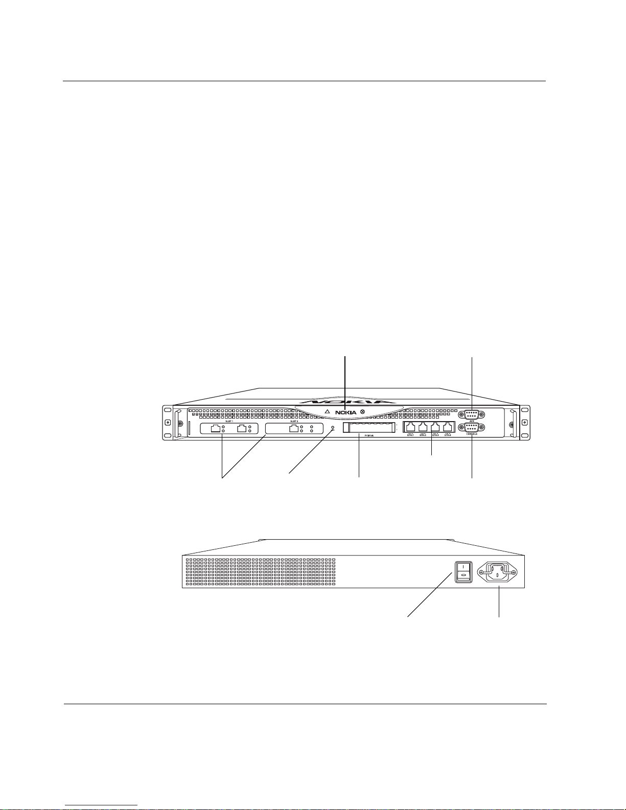
Nokia 100i Gateway Overview
The following figures show component locat ions fo r th e Nokia 100i gat eway .
Figure 1 Component Locations Front View
Status LEDs Modem (AUX) port
00248a
Management ports
PMC interfaces
Figure 2 Component Locations Rear View
16 Nokia 100i Installation Guide
PCMCIA slotsReset switch
Console port
00249
Power plugPower switch
Page 17

Preparing the Installation Environment
The following section describes environmental and safety precautions for the
gateway, including:
! Preparing the Installation Environment
! Safety Precautions
! Electrical Power Source
! Product Disposal
Preparing the Installation Environment
Before you install the gate way, make sure that the installation environment is
clean, dry, and dust free. Take the following precautions to maintain a safe
working environment and to avoid accidents:
! Inspect the area for hazards, such as bare wires and standing water.
! Remove scarves and neckties, jewelry, and other loose items before you
install the gateway.
! Do not remove the gateway cover under any circumstanc es.
Ventilation
Gateways can generate substa ntial he at during op eration a nd therefo re requir e
adequate ventilation. You might need to install the gateway in an airconditioned room to ensure that its internal cooling system can maintain
acceptable temperatures during operation.
Warning
Do not block any ventilation slots on the gateway. Internal components
might overheat and be damaged.
Nokia 100i Installation Guide 17
Page 18

1 Overview
Humidity and Temperature
During operation, ambient relative humidity should never exceed ninety
percent and ambient air temperature must remain between 32
(0° C and 45° C).
Safety Precautions
Follow these safety instructions whenever you are working with the gateway.
Caution
Read and follow all of these precautions before you work near any
power source.
! Circuit breakers must be installed in the fixed wiring on all circuits to
which the gateways are connec ted. Ensure that all of the circuit breakers
are easily accessibl e.
° F and 113° F
! For installations in North America, use a 120 VAC, 20A fuse circuit
breaker for the circuit branch.
! For installations outside North America that use 230 VAC, use a
230 VAC, 2A fuse circuit breaker.
! Use the gateway device within the electrical ratings indicated on the back
of the device and in the product documentation.
Follow the requirements of all building and electrical codes before, during,
and after installation of the gateway.
Warning
The gateway requires protection against short-circuits (overcurrent).
Always use overcurrent protection on all conductors of electrical current
to which the gateway is connected.
18 Nokia 100i Installation Guide
Page 19

Preparing the Installation Environment
Electrical Grounding
The gateway must always be connected using a grounding-type plug.
Warning
Make sure that the facility where the gateway is installed has proper
electrical grounding and is connected to that ground at all times during
operation.
Protection Against Lightning
Warning
Do not work on the gateway during an electrical storm. Do not connect or
disconnect any wires, including network or power connections. Whenever
the threat of lightning danger exists, avoid even touching the gateway.
This precaution is sensible for any electrical device during periods of
lightning activity.
Electrical Power Source
Warning
Do not open the gateway or remove the network interface card (NIC) from
the gateway. No user-serviceable or user-replaceable parts are present in
the gateway. Only authorized service personnel should repair or open the
gateway.
Warning
To reduce the risk of fire, electric shock, and injury, disconnect the power
cord and any cables that connect to the gateway before you open the
chassis and expose internal components. Even though the power switch
is turned off, power is still present inside the gateway.
Nokia 100i Installation Guide 19
Page 20

1 Overview
The gateway requires a clean and well-regulated power source, free from
power surges and line noise. When the gateway is configured as a cluster
(rather than as a standalone gateway), each gateway should have its own
power source installed on a circuit separate from all other gateways in the
cluster. This ensures that a power failure on one circuit can affect only one
device within the cluster.
All gateways incorporate an autosen si ng power supply device t hat us es either
low range (100 to 130 VAC), or high range (200 to 240 VAC) at
50 to 60 Hz. Check the gateway safety label for specifics.
Product Disposal
At the end of its useful life, the gateway must be disposed of in accordance
with all national, state, and local laws and regulations. The device contains
components (such as its lithium battery) that must be disposed of properly to
prevent damage to the environment. Contact your local waste management
agencies for specific guidelines.
Site Requirements
Before you install a Nokia 100i gateway, ensure that your computer room or
wiring closet c onfor ms to the envir onmental spec ific ation s l iste d in Appendix
A, “Technical Specifications,”
20 Nokia 100i Installation Guide
Page 21

Site Requirements
Warning
Hazardous radiation exposure can occur if you use controls, make
performance adjustments, or follow procedures that are not described in
this document.
Warning
An explosion can occur if the battery is incorrectly placed. Replace only
with the same or equivalent type battery recommended by the
manufacturer. Dispose of used batteries according to the manufacturer's
instructions.
Warning
To reduce the risk of fire, electric shock, and injury when you use
telephone equipment, follow basic safety precautions. Do not use the
product near water.
Caution
Do not place objects over the ventilation holes on the Nokia 100i
gateway. The components might overheat and become damaged.
Caution
For Nokia 100i gateway intended for shipment outside of the United
States, the cord might be optional. If a cord is not provided, use a
power cord rated at 6A, 250V, maximum 15 feet long, made of HAR
cordage and IEC fittings approved by the country of end use.
Nokia 100i Installation Guide 21
Page 22

1 Overview
22 Nokia 100i Installation Guide
Page 23

2 Installing the Gateway
Installing the Nokia 100i Gateway
The Nokia 100i supports up to ten Ethernet interfaces using two optional
expansion slots, in addition to the four built-in Ethernet interfaces. Each of
these expansion sl ots can accommodat e a Dua l Gigabit Ethernet car d (10/100/
1000BaseT), a Dual Fiber Gigabit Ethernet card, or a four-port 10/100
Ethernet card.
Note
In the Nokia 100i, you cannot use two PMC four-port 10/100 Ethernet
NICs at the same time. However, you can use one PMC four-port 10/100
Ethernet NICs in combination with any other network card that the Nokia
100i supports.
The front panel of the Nokia 100i gateway also contains:
! Two PCMCIA slots
! One console port
! One serial port
See Chapter 4, “Installing and Replacing Optional Cards,”
For technical specif ications, see Appendix A, “Technical Specifications,”
This section describes how to install the Nokia 100i gateway, including rack
mounting the Nokia 100i gateway.
Nokia 100i Installation Guide 23
Page 24

2 Installing the Gateway
Warning
To help guard against electrostatic discharge, follow the instructions on
the wrist strap envelope before you handle the accelerator card or open
the gateway.
Note
The operating temperature range for the Nokia 100i gateway is 32° F to
113° F (0° C to 45° C).
Rack Mounting the Nokia 100i Gateway
The Nokia 100i gateway mounts in a standard 19-inch rack with four
mounting screws, as Figure 4 shows.
install the two side brackets with
The brackets and screws are included with the materials you receive with the
gateway.
Before you mount the gateway on the rack,
four screws on each side, as shown in Figur e 3.
Two mounting positions are available, allowing you to mount the unit either
flush with the rack, or two inch es forward of the rack , as Figure 3 shows.
Figure 3 Adjustable Mounting Brackets
00251a
24 Nokia 100i Installation Guide
Page 25

Figure 4 Mounting Screws Location
Installing the Nokia 100i Gateway
Mounting screws
00248a
Nokia 100i Installation Guide 25
Page 26

2 Installing the Gateway
26 Nokia 100i Installation Guide
Page 27

3 Performing the Initial
Configuration
Performing the Init ial Hardware Configuration
The first time you t urn on power t o a Nokia 100 i gateway, t he initi al hardware
configuration process begins.
This section describes how to perform the initial configuration manually by
using a console connection. It includes the following sections:
! Connecting the Console Port
! Connecting Power and Turning the Power On
Note
Nokia recommends that you install all hardware components before you
perform the initial hardware configuration.
Nokia 100i Installation Guide 27
Page 28

3 Performing the Initial Configurati on
Connecting the Console Port
Use the built-in console port to su pply the informat ion that make s the gateway
available on the network. Use the built-in serial port (AUX) for
RS232-compliant equipment you are using with your gateway; for example,
as a modem connection for managing the gateway. “Pin Assignments fo r
Console and AUX Connections” on page 30 provides pin assignment
information for console and serial connections.
Caution
Nokia recommends that you use the console cable that was
delivered with your gateway for your console connection. Otherwise,
ensure that the pin assignments for your cable match those provided
in this section.
Note
Although pin assignments are the same for console and serial
connections, they are used differently by the gateway. Therefore, do not
use these two connectors interchangeably.
Use an ASCII terminal or a computer with terminal emulation software for
console communication.
The following terminal settings are required to communicate with the
gateway by using the console port:
! Baud rate—9600
! Data bits—8
! Parity—none
! Stop bit —1
! Flow control—none
28 Nokia 100i Installation Guide
Page 29

Performing the Initial Hardware Co nfi gura tio n
To connect to the console
1. Turn off power to the gateway.
2. Connect the supplied null-modem cable (console cable) to the console
port.
Note
On the Nokia 100i gateway the console port is located on the front of
the gateway.
Use only the DB-9 port labeled Console; the serial port AUX is an
auxiliary modem port.
If you connect the console port to a data-communications equipment
device, use a straight-through cable.
For cable pin assignments for the console connection, “Pin Assignments
for Console and AUX Connections” on page 30.
3. Connect the other end of the cable to a system running a
terminal-emulation program.
4. If you are using a flash memory card, insert the flash memory card into
the primary flash memory card slot.
The Nokia 100i has slots in the front panel for flash cards.
Note
Nokia recommends that you use the embedded flash memory on the
gateway instead of using the flash memory card. All gateway models
have internal flash memory.
a. Align the card with the slot so that the connector is inserted first.
b. Gently slide the card into the slot and press until you feel it seat into
the slot. If the card d oes not insert all the way, flip it over and
reinsert it.
Nokia 100i Installation Guide 29
Page 30

3 Performing the Initial Configurati on
5. Make sure that you have a ter mina l emul at or configured with the setti ngs
described in “Connecting the Console Port” on page 28.
6. Turn on power to the gateway.
Continue to “Connecting Power and Turning the Power On” on page 31.
Console Pin Assignments
Use the built-in console port to su pply the informat ion that make s the gateway
available on the network. Use the built-in serial port (AUX) for RS232compliant equipment you are using with your gateway; for example, as a
modem connection for managing the gateway. Figure 5 on page 30 provides
pin assignment information for console and serial connections.
Figure 5 Pin Assignments for Console and AUX Connections
1
69
5
00460
Input or
Pin # Assignment
1 DCD
(AUX port
only; not used
by the console
port)
2RXD Input
3TXD Output
4DTR Output
5GND
6DSR Input
7RTS Output
8CTS Input
9 not used
output
Input
30 Nokia 100i Installation Guide
Page 31

Performing the Initial Hardware Co nfi gura tio n
Table 3 on page 31 shows how to match pin s at the console or ser ial connector
with output pins on DB9 or DB25 cables you are using with terminal devices
or other appropriate equipment.
Table 3 Pin Assignments for DB9 and DB25 Interface Cables
Console or serial
pin and assignment
Shield (FG) Shield (FG) 1 (FG)
2 (RXD) 3 (TXD) 2 (TXD)
3 (TXD) 2 (RXD) 3 (RXD)
4 (DTR) 6 (DSR) 6 (DSR)
5 (SG) 5 (SG) 7 (SG)
6 (DSR) 4 (DTR) 20 (DTR)
7 (RTS) 8 (CTS) 5 (CTS)
8 (CTS) 7 (RTS) 4 (RTS)
DB9 cable-output pin and
assignment
DB25 cable-output pin and
assignment
Connecting Power and Turning the Power On
The power switch and r eceptacl e for th e power c ord are l ocated on the back of
the gateway, as shown in Figure 6.
The gateway power supply automatically detect s th e input voltage (120 VAC
[100 to 130] or 240 VAC [200 to 264]) and configures itself appropriately.
Nokia 100i Installation Guide 31
Page 32

3 Performing the Initial Configurati on
Figure 6 Power Switch Location on the Nokia 100i
00249
Power switch
Power plug
To connect the power
1. Connect the power cord securely into the power plug on the back of the
gateway.
2. Plug the other end of the cord into a three-wire grounded power strip or
wall outlet.
3. Press the power supply switch to the On position to provide power.
The fan unit turns on when you press the power switch. Verify that the
fans are running after you press the switch.
Check the power LED on the front panel of the gateway (the Nokia logo)
to ensure that the power supply is operating correctly. The power LED
should be illuminated.
If the power supply fans are not running, or if the power LED is not
illuminated:
! Check the power supply cord to make sure it is properly connected.
! Make sure the power supply switch is on.
! Make sure the chassis assembly is pu shed al l the way i n fro m the fr ont
of the gateway.
! Make sure that power is turned on to the power strip or wall receptacle
that you plugged the gateway in to.
If the fans are still not running, or if the power LED does not illuminate,
contact your Nokia service provider as listed in “Nokia Contact
Information” on page 3 for technical support.
32 Nokia 100i Installation Guide
Page 33

Performing the Initial Hardware Co nfi gura tio n
System Status LEDs
You can monitor the basic operation of the gateway and network interface
cards (NICs) by checking their status LEDs. The system status LEDs are
located on the front panel of the gateway.
Figure 7 Status LED Location for the Nokia 100i Gateway
Power status
Warning
Fault
Nokia 100i Installation Guide 33
Page 34

3 Performing the Initial Configurati on
Table 4 System Status LEDs for the Nokia 100i Gateway
LED Description
Steady blue: Power on.
!!
!!
Steady yellow: Unit is experiencing an internal voltage
problem or unit is booting.
Blinking yellow: Unit is experiencing a temperature
problem.
Steady red: One or more fans are not operating properly.
or
There is a DC voltage problem.
Connecting Network Interfaces
The Nokia 100i gateway supports the following for network communication:
One built-in four-port 10/100 Ethernet management interface; supports up to
six additional network interfaces (for a total of ten). The Nokia 100i also
supports a dual Gigabit Ethernet card (10/100/1000 Base-T), a dual Fiber
Gigabit Ethernet card, and a four-port 10/100 Ethernet card.
Note
In the Nokia 100i gateway, you cannot use two PMC four-port 10/100
Ethernet NICs at the same time. However, you can use one PMC fourport 10/100 Ethernet NICs in combination with any other NIC that the
Nokia 100i supports.
34 Nokia 100i Installation Guide
Page 35

For more informati on about the Gigabit Ether net c ards, s ee “I nstal ling a Fiber
Optic or Copper Gigabit Ethernet NIC” on page 55.
Ethernet Management Ports
The Ethernet management ports are located on the front of the gateway.
Figure 8 shows the layout of the Ethernet management ports and link LEDs.
Note
The Ethernet management ports are intended for management purposes.
These ports do not provide the same performance as Ethernet cards in
the PMC slots.
Figure 8 Ethernet Management Ports Details
Activity LED (yellow)
Link LED (green)
Connecting Network Interfaces
RJ-45 connectors
00120
Caution
Cables that connect to the Ethernet ports must be IEEE 802.3
compliant to prevent potential data loss.
Note
Nokia products only support NICs purchased from Nokia Corporation or
Nokia-approved resellers. The Nokia Global Support Services group can
only provide support for Nokia products that use Nokia-approved
accessories. For sales or reseller information, contact a Nokia service
provider listed in the “Nokia Contact Information” on page 3.
Nokia 100i Installation Guide 35
Page 36

3 Performing the Initial Configurati on
Connecting to Ethernet Ports
You can connect one network interface to the network to use as the Nokia
100i gateway inter face. You conf igure this interfa ce during the system start up
procedure, which is described in Performing the Initial Gateway
Configuration in the Nokia IP VPN Gateway Configuration Guide.
You can also connect the remaining LAN and WAN interface cables at this
point, although you are not required to do so.
After the power is turned on, the Ethernet link LEDs on the gateway and on
remote equ ipment illuminate to indicate the connection. As data is
transmitted, the activity LEDs on the gateway illuminate.
Ethernet Cables
Use IEEE 802.3 10 Base-T, 100 Base-TX CAT-5 unshielded twisted-pair
CAT-5 Ethernet cables.
To connect Ethernet devices:
! Use a straight-thro ugh RJ- 45 c abl e t o connect to a 10-Mbps or 1 00- Mbp s
hub or switch.
! Use a crossover RJ-45 cable to connect directly to a host.
After you connect t he network int erfaces, con tinue with Per forming the In itial
Gateway Configuration in the Nokia IP VPN Gateway Configuration Guide.
36 Nokia 100i Installation Guide
Page 37

Connecting Network Interfaces
Ethernet Cable Pin Assignments
Figure 9 shows the pin assignments for an RJ-45 cable. The RJ-45 cable
output connector is numbered from left to right, with the copper tabs facing
down and toward you.
Figure 9 Output Connector for the Ethernet Cable
Gigabit
10/100 Mbps
Pin #
1 TX+ BI_DA+
1
8
00270a
2 TX- BI_DA3 RX+ BI_DB+
4 BI_DC+
assignment
Ethernet
assignment
5 BI_DC6 RX - BI_DB7 BI_DD+
8 BI_DD-
Figure 10 on page 38 shows the pin assignments for the RJ-45 crossover
cable.
Nokia 100i Installation Guide 37
Page 38

3 Performing the Initial Configurati on
Figure 10 Ethernet Crossover-Cable Pin Connections
1
2
3
4
5
6
7
8
1
2
3
4
5
6
7
8
00017.1
You can order appropriate adapter cables separately. To order additional
cables, contact your cable vendor.
38 Nokia 100i Installation Guide
Page 39

4 Installing and Replacing
Optional Cards
This chapter provides information about how to install or replace optional
cards for the Nokia 100i.
The following topics are covered:
! Before You Begin
! Installing Flash Memory PC Cards
! Installing an Encryption Accelerator Card
! Install ing a Network Interface Card
Before You Begin
Before you install the card, you need:
! Physical access to the gateway
! A Phillips-head screwdriver
! Suitable, grounded work surface
! Replacement unit kit, including the card
Nokia 100i Installation Guide 39
Page 40

4 Installing and Replacing Optional Cards
Caution
Protect your gateways and other electronic equipment from
electrostatic discharge damage by making sure you are properly
grounded before you touch any component.
Caution
When you handle a NIC, take care not to damage the EMI shield on
the top edge of the faceplate.
Installing Flash Memory PC Cards
This section provides information about how to install or replace additional
nonvolatile rand om ac ces s memory in your gateway by u si ng a fl ash memory
flash card.
You can order flash memory cards separately and use them with the Nokia
Nokia 100i gateway. The 100i gateway has two PC-card slots that each
support a flash memory card as small as 8 MB and as large as 64 MB. The
slots, also known as PCMCIA slots, permit hot swapping. The two slots are
located on the front panel.
Flash memory cards provide the following:
! Data storage
! Backup and storage of operating system and applications
! Initial gateway configuration
! Operating system booting
The default boot order is:
1. External flas h memory (PC card)
2. Internal fl ash memory
40 Nokia 100i Installation Guide
Page 41

Installing Flash Memory PC Cards
You can only boot from slot 1, even if you use two cards. To boot from the
flash memory card, the card needs to be in slot 1 (the top slot) already before
and during the reboot. You can install the cards in either of the PC slots,
which are accessible from the front of the gateway, as shown in Figure 11 on
page 41.
Note
Use the top PC slot for optimum electrostatic discharge protection.
Figure 11 PC Card Slots on the Nokia 100i
00248a
Eject Buttons
Slot 1
Slot 2
To install and remove the flash memory PC card
1. Insert the flash memory card into PC card slot 1, if it is availa ble.
If slot 1 is occupied, use slot 2.
2. Press gently on the car d until it is firmly seat ed in the slot.
The eject button to the right of the slot should be flush with the card.
3. To remove the card, sl owly push the ej ect button loc ated to the right of the
card.
Nokia 100i Installation Guide 41
Page 42

4 Installing and Replacing Optional Cards
Installing an Encryption Accelerator Card
This section describes how to replace the Nokia Encryption Accelerator Card.
The card is included with the Nokia 100i gateway and installed before the
gateway is deli vered to you. Th ese inst ructions apply o nly if you are r eplacing
the card.
The Nokia Encryption Accelerator Card provides high-speed cryptographic
processing that enhances the performance of VPN tunnels. By taking over
cryptographic processing, the card allows the gateway CPU to perform other
tasks.
The Nokia Encryption Accelerator Card is in a PMC format for the Nokia
100i. This card has no external cable connection ports and requires no cables.
The following security algorithms are supported:
! MD5 and SHA-1 authentication
! DES and 3DES encryption
! 128-bit, 192-bit, and 256-bit AES encryption
To install the Nokia Encryption Accelerator Card on the Nokia
100i
1. Turn off the power switch on the rear of the gateway and unplug the
power cord.
Note
If you cannot access the power switch, you can still perform this
procedure. When the slide tray assembly is removed from the chassis
assembly, power to a Nokia 100i is automatically disconnected.
42 Nokia 100i Installation Guide
Page 43

Installing an Encryption Accelerator Card
2. Loosen the two front-panel retaining screws.
00248a
Chassis assembly retaining screws
3. Completely remove the slide tray a ssembly from the chassis assembly to
expose the motherboard components.
4. Locate the 33-MHz PMC connectors on the rear of the mo therboard .
Note
Make sure you locate the correct connectors for the Nokia Encryption
Accelerator Card. Do not use the PMC connectors located at the front
of the motherboard; those connectors are for network interface cards.
Nokia 100i Installation Guide 43
Page 44

4 Installing and Replacing Optional Cards
5. Position the male PMC connectors on the Nokia Encryption Accelerator
Card over the female PMC connectors on the motherboard.
AB
Standoffs
Insert the card into
connectors. Screw
card into standoffs.
Align the two sets of conn ector s with eac h other, and al ign the fou r screw
holes and four standoffs with one another.
6. Push down on the card until it is properly seated on the motherboard.
00267
44 Nokia 100i Installation Guide
Page 45

Installing a Network Interfac e Ca rd
7. Place the screws through the standoff holes on the card and into the
standoffs on the motherboard.
Screw
Accelerator card
Standoff hole
Motherboard standoff
8. Turn each screw clockwise to attach the card to the standoffs.
Do not tighten completely.
9. Make sure that all four standoff connections are properly aligned.
10. To secure the connections, tighten the screws firmly, but do not
overtighten.
11. Slide the chassis assembly back into the gateway and resecure the two
retaining screws.
Reseating the chassis assembly automatically restores power to the
gateway.
The accelerator card is automatically detected and e nabled by default.
Installing a Network Interface Card
All network interface cards (NICs) installed in the Nokia 100i gateway are
installed in the 6U PMC car ri er . Eth ern et NI Cs c an oc cupy any of the slots or
subslots in a gateway that other I/O cards do not occupy.
Nokia 100i Installation Guide 45
Page 46

4 Installing and Replacing Optional Cards
This section describes how to install an Ethernet NIC in the Nokia 100i
including:
! Adding or removing the NIC card by using VPN Manager
! Physically installing the NIC on the 100i gateway
Note
Nokia recommends that you add or remove the card in the VPN Manager
software before you physically install or remove the card.
Installing a Network Interface Card by Using Nokia
VPN Manager
To add or remove a NIC by using VPN Manager
1. From the VPN Manager main window, double-click the interface to add
or remove.
The Gateway Properties window opens.
46 Nokia 100i Installation Guide
Page 47

Installing a Network Interfac e Ca rd
2. From the Gateway Properties Sett ings pane, select Iden tity > Interfaces:
! To add a card, click Add.
! To remove a card, click Remove.
Nokia 100i Installation Guide 47
Page 48

4 Installing and Replacing Optional Cards
The Add Slot-based interface window opens.
3. From the drop-down lists:
a. Select the card to add or remove:
! 1000BaseTX (Copper) 2 ports
! 1000BaseTX (Fiber) 2 ports
! four-port 10/100 Ethernet 4 ports
b. Select the slot number:
! Choose Slot 1
! Choose Slot 2
4. Click OK.
When the card and slot are identified, VPN Manager automatically generates
and names the corresponding new interfaces. For example, eth-sxpz, where x
is the slot number and z is the port numbe r on the car d. For th e fiber optic and
copper Gigabit Ethe rnet car ds, this mi ght be slo t 1 or 2 and port 1 or 2 . For th e
four-port 10/100 Et he rne t c ard , this might show slot 1 or 2 and port 1, 2, 3, or
4. VPN Manager then places the new interfaces on the VPN Manager user
interface and yo u can c onfigu re them the same a s an y other Ethern et i nterfac e.
48 Nokia 100i Installation Guide
Page 49

Installing a Network Interfac e Ca rd
Installing a NIC on the Nokia 100i Gateway
Note
f you cannot access the power switch, you can still perform this
procedure. When the slide tray assembly is removed from the chassis
assembly, power to a Nokia 100i is automatically disconnected.
To physically install a NIC on the Nokia 100i gateway
1. Identify the location (PMC carrier and slot) of the NIC to be replaced.
2. Turn off the power switch on the rear of the gateway and unplug the
power cord.
3. IUse your fingers or a screwdriver to loosen the retaining screws that hold
the chassis assembly.
00248a
Chassis assembly retaining screws
Nokia 100i Installation Guide 49
Page 50

4 Installing and Replacing Optional Cards
4. Completely remove the slide tray a ssembly from the chassis assembly to
expose the motherboard components and locate the NIC connectors.
5. From underneath the chassis assembly , remove the bezel reta ining scre ws.
00252a
If you are installing a NIC in an unoccupied slot, remove the blank bezel
that occupies the space in the gateway f ron t panel, retain it for future use,
and proceed to step 8.
50 Nokia 100i Installation Guide
00254b
Page 51

Installing a Network Interfac e Ca rd
6. From the chassis assembly, remove the NIC retaining screws from the
back of the NIC.
00255a
7. Remove the NIC by lifting the back of the NIC away from the chassis
assembly and pulling the NIC gently away from the front panel.
Nokia 100i Installation Guide 51
00257
Page 52

4 Installing and Replacing Optional Cards
8. Insert the new NIC into the front panel.
9. Gently push the back of the NIC down toward the chassis assembly.
Make sure th at the NIC edge is completely seated into the connectors o n
the chassis assembly.
00256a
10. From the top of the chassis assembly, screw the NIC retaining screws into
the standoffs on the back of the NIC.
00255b
52 Nokia 100i Installation Guide
Page 53

Installing a Network Interfac e Ca rd
11. Fro m beneath the chassis assembly, screw in the bezel retaining s crews.
00254b
12. Close the chassis assembly until it clicks into place.
00252c
13. Tighten the retaining screws that hold the chas sis assembly.
The system automatically restarts when t he chassis a ssembly cl icks into
place.
The Nokia 100i gateway automat ically det ects any new NIC when t he syste m
is restarted.
Nokia 100i Installation Guide 53
Page 54

4 Installing and Replacing Optional Cards
Installing a Four-port 10/100 Ethernet NIC
This section provides information about the dual-mode 10-Mbps and 100Mbps Ethernet network interface card (NIC) that you can use with the Nokia
100i gateway.
All NICs for the Nokia 100i gateway are installed into slots on the gateway.
The Nokia 100i supports using a maximum of one four-port 10/100 Ethernet
NIC per unit. The 10/100 Ethernet NIC provides the following features:
! Tracing with tcpdump
! Compliance with IEEE 802.3 Ethernet specification
You can configure the Ethernet interfaces with Nokia VPN Manager. See
Performing the Initia l Gateway C onfigurat ion in the Nokia IP VPN Gateway
Configuration Guide.
To physically install the four-port 10/100 Ethernet NIC, see “Installing a
Network Interface Card by Using Nokia VPN Manager” on page 46.
Front Panel Details
Figure 12 shows the front panel details for the four-port Nokia 10/100
Ethernet NIC.
Figure 12 PMC Four-port 10/100 Ethernet NIC
Ports
Link LEDs (steady green)
Activity LEDs (blinking green)
54 Nokia 100i Installation Guide
Page 55

Installing a Network Interfac e Ca rd
Note
In the Nokia 100i, you cannot use two PMC four-port 10/100 Ethernet
network cards at the same time. However, you can use one PMC fourport 10/100 Ethernet NIC in combination with any other NIC that the
Nokia 100i supports.
For connectors and cable information for the four-port 10/100 Ethernet NIC,
see “Ethernet Management Ports” on page 35.
Caution
Cables that connect to the Ethernet NIC must be IEEE 802.3
compliant to prevent potential data loss.
Installing a Fiber Optic or Copper Gigabit Ethernet NIC
This section provides information about the PMC fiber optic or copper
Gigabit Ethernet network interface cards (NICs), which you can use with the
Nokia 100i gateway.
The fiber optic Gigabit Ethernet NICs provide the following features:
! High bandwidth
! Full-duplex mode operation up to 1 Gbps (no half-duplex support)
! Link speed autoadvertising
! Compliance with IEEE 802.3z Gigabit Ethernet specification
You can configure and manage Ethernet interfaces with Noki a VPN Manager
software. See Chapter 4, Installing Nokia VPN Manager and the Gateway in
the Nokia IP VPN Gateway Configuration Guide.
To physically install the fiber optic or copper Ethernet NIC, see “Installing a
Network Interface Card by Using Nokia VPN Manager” on page 46.
Nokia 100i Installation Guide 55
Page 56

4 Installing and Replacing Optional Cards
Front Panel Details
Figure 13 shows the front panel details for the dual-port fiber optic Gigabit
Ethernet NIC.
Figure 13 PMC Dual-Port Fiber Optic Gigabit Ethernet NIC
Port 1 (P1) Port 2 (P2)
GIGE
Figure 14 shows the front panel details for the dual-port copper Gigabit
Ethernet NIC.
00239b
Link LED (green)
Activity LED (yellow)
Figure 14 PMC Dual-Port Copper Gigabit Ethernet NIC
Link LEDs (green or yellow)
Activity LEDs (yellow)
Ports
GIG E
LINK
ACT
1
2
LINK
ACT
00386.2
For the PMC format cards, the link LED on the NIC is bicolored. A green
LED indicates a 1 Gbps link speed, and a yellow LED indicates a 10/100
Mbps link speed. As t he NIC tran smits data, t he activ ity LEDs on the gatewa y
illuminate.
56 Nokia 100i Installation Guide
Page 57

Connectors and Cables
This section provides information about the cables used with the fiber optic
Gigabit Ethernet card and the copper Gigabit Ethernet card.
Caution
Cables that connect to the Gigabit Ethernet card must be IEEE 802.3
compliant to prevent potential data loss.
Fiber Optic Gigabit Ethernet NIC
To connect the fiber optic Gigabit Ethernet NIC to ot her network compon ents,
use a multimode, fiber optic cable with an LC connector for each NIC
interface. The destination end of the cable can be either LC or SC, depending
on the type of connector required for the destination Gigabit Ethernet device.
You can also use a hal f- dupl ex L C-to-LC cable to loop back the transmit port
of an interface t o the rece iver port . LC and SC defin e the fibe r optic co nnector
types. LC connectors are smaller than SC.
Installing a Network Interfac e Ca rd
Two LC-to-SC cables are i nclud ed wi th du al-po rt f iber optic Gigabi t Eth ernet
NICs. To order additional cables, contact your cable vendor.
Copper Gigabit Ethernet NIC
All Nokia copper Gigabit Ethernet NICs support cable autosensing. You can
use a straight-through or crossover cable to connect the NIC to a Gigabit hub
or switch or to connect directly to a host.
For more information about the Ethernet cables, see “Connecting Network
Interfaces” on page 34.
Nokia 100i Installation Guide 57
Page 58

4 Installing and Replacing Optional Cards
58 Nokia 100i Installation Guide
Page 59

5 Troubleshooting
This chapter provides troub le shooting tips, problems, and sol ut io ns rel at ed to
installations.
Gateway Not Receiving Power
Problem Power cord is not properly plugged in.
Solution Check cord. Make sure it is properly seated at both ends.
Problem Power supply not providing power.
Solution Check power sou rce. If t he sou rce has no power , take approp riat e
action such as inserting a new fuse or resetting the circuit breaker.
Unable to Log In to the Console Port—No Error Message
Two computers (using terminal-emulation programs) or terminals should be
able to communicate back to back in the same way that the terminal
communicates with the gateway. If this is not possible with your computer or
terminal, the problem is with the terminal o r cable and not with the gateway.
Problem No console connection to the gateway.
Solution For information about how to create a console connection, see
“Connecting the Console Port” on page 28.
Nokia 100i Installation Guide 59
Page 60

5 Troubleshooting
Problem Not connected with a null-modem cable.
Solution Verify that you are using a null-modem cable.
Problem Wrong terminal settings.
Solution Verify terminal settings: 9600 bps, 8 data bits, 1 stop bit, no
parity.
Problem Defective gateway or file system.
Solution Contact the Noki a cus tome r sup port site listed in “Nokia Contact
Information” on page 3.
Do Not Get a Login Prompt—Error Messages Appear
Problem The gateway is defective, or the file system on the gateway is
defective.
Solution Contact the Noki a cus tome r sup port site listed in “Nokia Contact
Information” on page 3.
Do Not See Interfaces that Should be Present
Problem Local gateway ports do not appear.
Solution Your network interface card (NIC) might be defective. Contact
the appropriate Nokia customer support site as listed in “Nokia Contact
Information” on page 3.
Note
With a Nokia 100i, the problem might be with the I/O slot. Try installing the
NIC in another slot.
60 Nokia 100i Installation Guide
Page 61

Common Ethernet Problems—Connectivity with Attached
Device
Problem No link light.
Solution You might have used the wrong cable. Use a crossover cable
between the gateway and a host, and a straight-through cable between a
gateway and a hub.
Problem Steady activity LED.
Solution You might have set the wrong speed. Verify that t he speeds match
on each end of the Ethernet connection (10 Mbps, 100 Mbps, or 1000 Mbps).
Problem Port not enabled.
Solution Verify from the Interfac e page in Nokia VPN Man ager that the
interface port is configured as active.
Problem High collision rate on the hub.
Solution Disconnect connections one at a time until the problem is
localized to one computer and troubleshoot further.
Nokia 100i Installation Guide 61
Page 62

5 Troubleshooting
62 Nokia 100i Installation Guide
Page 63

A Technical Specifications
Physical Dimensions
Dimensions
Weight
Space Requirements
The Nokia 100i is designed for front-screw mounting in a 19-inch rack. Each
100i requires the following space in a rack:
! 1.75 inches (4.45 centimeters) of vertical space
! 18 inches (46 centimeters) behind the front-panel of the rack
! 6 inches (15 centimeters) behind the 100i gateway to allow the back exit
fan to move air through the gateway.
Height: 1.75 in. (4.45 cm)
Width: 17 in. (44 cm)
19 in. (48 cm) rack mountable
Depth: 16.12 in. (40.94 cm)
17 lbs. (7.7 kg) base syst em
Nokia 100i Installation Guide 63
Page 64

A Technical Specifications
Caution
Do not place objects over the ventilation holes on the 100i gateway.
The gateway might overheat and become damaged.
NIC Interfaces
Cable Type
Cable Output
Connector
Ethernet IEEE 802.3 10BASE-T,
100BASE-TX unshielded
twisted pair, full-duplex or
half-duplex
RJ-45
64 Nokia 100i Installation Guide
Page 65

B Compliance Information
This appendix contains the following compliance information:
! Declaration of Conformity
! Compli ance Statements
! FCC Notice (US)
Nokia 100i Installation Guide 65
Page 66

B Compliance Information
Declaration of Conformity
According to ISO/IEC Guide 22 and EN 45014:
Manufacturer’s Name: Nokia Inc.
Manufacturer’s Address : 313 Fairchild Drive
Mountain View, CA 94043-2215
USA
declares that the product:
Product Name: 100i
Model Number: IP0380
Product Options: All
Serial Number: 1 to 100,000
Date First Applied: 2005
conforms to the following standards:
Safety: UL60950, 3rd Edition (2000); CA N/C SA-C22. 2
No.60950-00, 3rd Edition (2000); IEC60950-1
(2001); EN60950-1(2001)+A11
EMC: EN55024 1998, EN55022A 1998, EN61000-3-2,
EN61000-3-3
Supplementary information:
66 Nokia 100i Installation Guide
Page 67

Compliance Statements
Pursuant to directive 1999/5/EC this product complies with the
requirements of the Low Voltage Directiv e 73/23/E EC and the EMC
Directive 89/336/EEC with Amendment 93/68/EEC.
Christopher Saleem
Compliance & Reliability Engineering Manager
Security & Mobile Connectivity, Enterprise
Solutions
Mountain View, California
Elie Habib
Senior Vice President
Security & Mobile Connectivity, Enterprise
Solutions
Mountain View, CA
Compliance Statements
This hardw are complies with the standards listed in this section.
Emissions Standards
FCC Part 15 Subpart B Class A US/Canada
EN55022 (CISPR 22 Class A) European Community (CE)
Nokia 100i Installation Guide 67
Page 68

B Compliance Information
Immunity Standards
EN55024 European Community (CE)
EN61000-4-2
EN61000-4-3
EN61000-4-4
EN61000-4-5
EN61000-4-6
EN61000-4-11
Harmonics and Voltage Fluctuation
EN61000-3-2 European Community (CE)
EN61000-3-3 European Community (CE)
Safety Standards
UL60950/EN60950 US/European Community(CE)
CAN/CSA-C22.2 No.60950 Canada
FCC Notice (US)
This device has been tested and found to comply with the limits for a Class A
digital device , pursuan t to Part 1 5 of th e FCC Rul es. The se limi ts are designed
to provide reasonable protection against harmful interference in a residential
installation. This device generates, uses, and can radiate radio frequency
energy and, if not installed and used in accordance with the instruction, m ay
cause harmful interference to radio communications. However, there is no
68 Nokia 100i Installation Guide
Page 69

FCC Notice (US)
guarantee that interference will not occur in a particular installation. If this
device does cause harmful in terference to radio or television reception, the
user is encouraged to try to correct the interference by one or more of the
following measures:
! Reorient or relocate the receiving an tenna.
! Increase the separation between the computer and receiver.
! Connect the computer into an outlet on a circuit different fro m that to
which the receiver is connected .
! Consult the dealer or an experienced radio/TV technician for help.
Caution
Any changes or modifications not expressly approved by the grantee
of this device could void the user’s authority to operate the
equipment.
Nokia 100i Installation Guide 69
Page 70

B Compliance Information
70 Nokia 100i Installation Guide
Page 71

Index
Numerics
100i gateway 15
A
accelerator card 42
appliance components 16
attaching accelerator card to motherboard 45
C
cables
null-modem 29
pin assignments 37
configuring
terminal settings 28
connecting console, to the 29
connections
Ethernet cr ossover-cabl e pin 38
Ethernet port 36
pin assignments for modem 31
power 31
RJ-45 37
console
cable connection 29
terminal settings 28
console port 23
copper Gigabit Ethernet NIC 55
D
data communications equipment device 29
documentation
structure 9
E
encryption accelerator card 42
Ethernet
cable pin assignments 37
crossover-cable pin connections 38
ports, connecting to 36
Ethernet management interface 34
Ethernet management ports 35
Ethernet NIC 54
F
fiber optic Ethernet NIC 55
flash memory cards 40
four-port 10/100 Ethernet NIC 54
G
gateway
electrical groundin g 19
humidity 18
temperature 18
ventilation 17
Nokia 100i Installation Guide Index - 71
Page 72

I
installation
electrical groundin g 19
environment 17
network interface cards 46
temperature 18
ventilation 17
installing NICs 55
interfaces
specifications 64
L
LEDs 33
M
management ports 35
modem connection, pin assignments 31
N
network interface card, installing 46
network interface cards
front panel location 16
types supported 35
null-modem cable 29
R
reset switch 16
RJ-45 connector 37
S
safety, power source 19
serial port 23
space requirements 63
specifications
interfaces 64
specifications, technical 63
T
technical specifications 63
terminal settings 28
O
output connector, Ethernet cab le 37
P
PCMCIA slots 23
pin assignments, modem connections 31
pin connections, Ethernet crossover-cable 38
power connections 31
power source, safety 19
Index - 72 Nokia 100i Installation Guide
 Loading...