

Page 1
EPHHI
CHINA CEPREI
No.60 Wbn Ming
Longquangyi Chengdu
(SICHUAN)
Dong Road
610100
DECTARATION
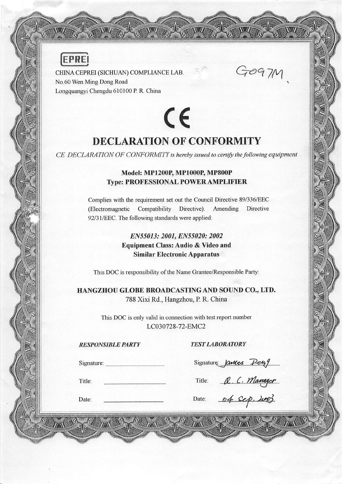
DECLARATION OF
CE
Type: PROFESSIONAL
Complies
(Electromagnetic
92l3IlEEC.
with the requirement
COMPLIANCE
P. R. China
LAB.
((
OF CONT'ORMITY
CONFORMITY
Model:
The following standards were applied:
MP1200E MP1000B MP800P
Compatibility
8N55013:
Equipment Class: Audio
Similar Electronic
ts hereby issued
POWER AMPLIFIER
set out
2001, 8N55020:
Corurcil
the
Drective). Amending
2002
& Video and
Apparatus
to ceftify
Directive
QeqZM
the
following
89l336lEEC
Directive
equipment
This DOC
is responsibility of the
HANGZHOU GLOBE
788 Xixi Rd., Hangzhou,
DOC is only
This
KESPONSIBLE
Signature:
Title:
Date:
PARTY
Name Grantee/Responsible
BROADCASTINGAND
P. R. China
valid in connection
with test report
LC030728-72-EMC2
TESTLABORATORY
Signatnq:@
Title:
Date:
SOUND
number
Party:
CO.,
LTD.
Page 2
T
t
T
f
n
f
f
f
t
t
I
T
i
t
EMC
HANG
Report
This
Orlginal
X
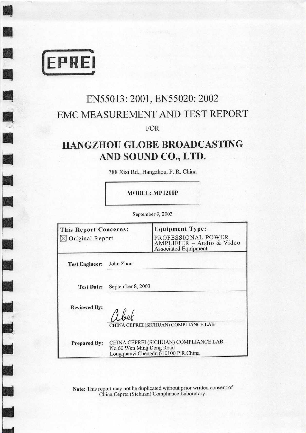
EN550
13 :
2001
EN5
,
MEASUREMENTAND
FOR
Z]HOU
AND
788
Concerns:
Report
GLOBE
SOUND
Xixi Rd.,
Hangzhon,
MODEL:
September
MP1200P
9,2003
Equipment
PROFESSIONAL
AMPLIFIER
502A:
TEST
BROADCASTING
P.
LTn.
R.
China
CO.,
2002
Type:
-
Audio
REPORT
POWER
Video
&
tt
I
T
I
T
l,'
I
I
T
I
F
F
TestEngineer:
Date:
Test
This
By:
report
China
Prepared
Note:
JoInZhou
SePtember
CHINA
CHINA
No.60
may
Ceprei
8,2003
CEPREI
CEPRXI
Wen
uanvi
not be
(Sichuan) Compliance
(SICHUAN)
(SICHU-AN) COMPLIANCE
Dong
Ming
Chensdu
duplicated
COMPLIANCE
Road
610100
P.R.China
without
prior
Laboratory.
LAB
written
LAB'
consent
of
p
tc
Page 3

TABLE OF CONTENTS
.AND=
OO_P
EMISSION TEST
1 - GENERAL
1.2
OBJEc'fl \,E..............
1.7
SUPPoRT EeUtPMEN'
I-ocAL
DATA AND R8S1ILTS............
INFORMATION......
2 - SYSTEMTEST CONFIGURATION
pMENT
2.3 EQ til
2.4
C--oNrrrcu RA'r'roN oF
3 . MAINS TERMINAL DISTURBANCE
3.1 i\4EASURENTENT 1INc8RTArNTy.........................
3.4 Tf,sr PRocEDURE.......
4 - DISTURBANCE POWER
N{oDrFrcA'fl oN"s
TEST
SYstErlr...............
VOLTAGE TEST D.4,TA........
TEST DATA
....................
4
........,.....,.7
..".................
8
..........I0
l0
s - I{ARMONIC
Appl.rcA'fl
5. I
5.2 MEASTTRENTENT DATA.......
5.3 TEs'r' REsrJl.r's......................
oN
oF
CURRENT
I{ARMoNrc
TEST
CURRENT
6 - VOLTAGE FLUCTUATIONS
6.I f\PPLICATION OF
6.2 ME,\SURENt Eh*T DATA....
VOLTACE FLUCTTIATIONS
IMMUNITY TEST DATA AND
1.2 OBJE('r'rvE..
TEsr METlloDol-ocy............
1.3
pilrENT
1.5 Eeur
UNocn
Report No. LC030728-7
(EtlT)
Tesr
2-EMC2
GENER{t-
DATA
8MrsstoN......,...........,...
(81"161000-3-2)..............
AND FLICK TEST DATA
AND FLTCK TEST,
DEscRlP.noN....
Page 2 of38
...........11
..............................,..
I I
(EN6lOOO-3-3)................................13
...................
........................,...
EN550l 3,
EN55020
I 3
I
6
Report
Page 4
I
I
n
;
T
t
t
t
T
HAILGZHOIIGLO-BE-BROALCjSINCAND-IAIn
2 - SYSTEM TEST
SPECTAL {ccEssoRlEs
2.2
3 - MBASUREMENT
'I'Es'r'
3.6
{.3..\.PPLICATION OF
4.5 AppLtcA'rroN oI IM[ruNrry
4.6 DEvlATloNs FRoNr rHE STANDAR
5 - TEST DATA
5.2
ELEcrRosrATrc
Ierjr
prvrEN'r
CONFIGURATION
INSTRUMENTATION.
........
Lrsr
ELECTROI\I.{CNETIC
ro INDUCTED \/o[,TAGI
f)rscHARcE
FIEI-D
IN,r MUNITY
TEsT........................
I,!IMTINITYTOST...,.......,.
o[ MArNS
{D!O*IL-ID,- -- ---'---*Modc-LMPl2O0P
TER]VIrNAL/AuDlo INPUT/OIirPUT
...............17
l7
........................18
...18
....20
TERi\'l1NAL...............................'..'.'
................,r
20
,,.,.20
1l
I
T
T
I
T
I
:
t
6 - PRODUCT
6.1 CE MARK l,ABELSpEcrFrcATloN...............
LABELING...........
t
.i
T
il
F
Report No.
LC0301
28
-7
2-EMC2
Page 3 of38
8N5501
3,
EN55020
Report
Page 5

HATLG_ZHOU
GLOBE
BROADCASTIW
-----_---
r4odgL-MPl2OOP
EMISSIOI{
PART
TEST
I
DATAAND
RESULTS
Report
No. LC03
0728-7 2-EMC2
Page 4
of3B
EN55013, 8N55020
Reporl
Page 6

I|
n
n
n
t
H
!f
f,
f
r
HANCZHOU*G-LOB-E-B-ROADCASTIIGAND-S-QUN-DCO*L-,ID-
1 . GENERAL
1.1 Product
The
HANGZHOU
referred
1.2
]]e {o,llowilg
HANGZHOU
Iirnits
The
Video
1.3
AII
Methods
range
characteristic
(Sichuan)
to in this
Objective
and methods
objective of the
Associated
Test Methodology
measurements
of Measurement
of 9 kHz
of
Laboratory.
INF'ORMATION
Description
GLOBE BROADCASTING
report is a
Declaration
GLOBtr
of
manufacturer is
Eq r-ri
contained
to 40 GHz & EN55013/CISPR
Audio
for Equipment
PROFESSIONAL POWER
of Conformity report
BR.OADCASTING
rneasurement
prnent.
in this report are
Radio-Noise
of
& Video Associated Equipment.
of radio
to dernonstrate
interference
Emissions
Under Test
AND
SOUND CO.,
AMPI-IFIER.
of ALrdio &
AND
soUND
characteristic
compliance
conducted
13
standard,
with EN550l
frorn
All emission
(BUT)
Video Associated
C0., LT'D. in
with EN550l3/CISPR
Low-Voltage
and for rnethods
---
LTD., model MP1200P
Equiprnent
accordahce with ENssOl3/CISPR
of Audio
3: 2001European
Electrical
measurements
& Video Associated
of measurement of radio
-*--Model:]42,00P
or
prepared
is
l3 limits for
National
ahd Electronic
performed
are
the "E[JT" as
on behanf of
13,
Equipme,nt.
Audio &
Standard for
Equipment in the
disturbance
at China Ceprei
f
H
t
H
T
n
H
1.4 Test
The Test
building atNo.60
1.5
Facilify
site used
Test Equipment
Description
l6,{
LINE Impedance
stabilization
EMI
Absorb
Harmonic
by China Ceprei
Wenming
Receiver
Test
East
List and Details
network
Clamp AFJ/AC-101
Meter
(Sichuan)
Street Longquan
Model
AFJ/LSI6C 160t0020077
AH/8R55
CR/2.8 9KHz-
2800M112
EMC
PARTNER/HAR
MONICS-1OOO
Laboratory
to collect
District,
Serial Number
emission
Clrengdu, P. R.
55790015165
43256221A98 Bl15l03 Bl1sl04
IJAR1000-40 3t06t03 3la6l04
measLlrernents data is located in the
China
tast
Cal.
r Date
Bltsl03 8/15/04
8/1s/03 8115104
Cal.
Date
Due
U
F
f
*Statement
perforrned
been
Report
No. LC03 0728-7 2-EMC2
of
Traceability: China Ceprei
usirrg suitable standards traceable
(Sichuan)
Laboratory
to the CHINA SCEIENTIFIC
Page 5
of38
certifies that all calibrations have
MEASUREMENT
EN550l
EN55020 Report
3,
INSTITU'IE.
Page 7
HAN
1.6
Equipment
Under Test (EUT)
DiaUN-D-eO-*tID--------.--Model,MP-U-A0P
General Description
1.7
Local Support
1.8 External
Cable Descriptign
Manufacturer
GLOBE
Equipment
Manufacturer
YONGMING
HONGXING
(No)
IiO
Cabling List
Description
PROFESSIONAL
POWER AMPLIFIER
List and Details
Description
Generator
Voltage Meter
4 O Load
and Details
:
tr I
tengthl(M)
,
Model
MPI2OOP
M
YM-1000
HX I 840-55
No
From/Por{
del
'Serial,Number
,
:;t
i
,
;t
Serial
I
No
Number
No
No
No
To/Port
Audio
Cable 1.5
Audio
Cable 1.0
Por.ver
Cable
t^
l.z
x2
Genelator
EUT
EUT
EUT
Load
Mains
Report
No. LC03
0728-7 2-EMC2
Page
8N550 13, EN55020 Reporl
6 of38
Page 8
||
n
:
HANGZHaU-GI-O-B-E-BRQADCAS-IING-ANDIO-UND-eO*ILD-----------Modd:M-PI200I
t
n
n
I
n
t
n
T
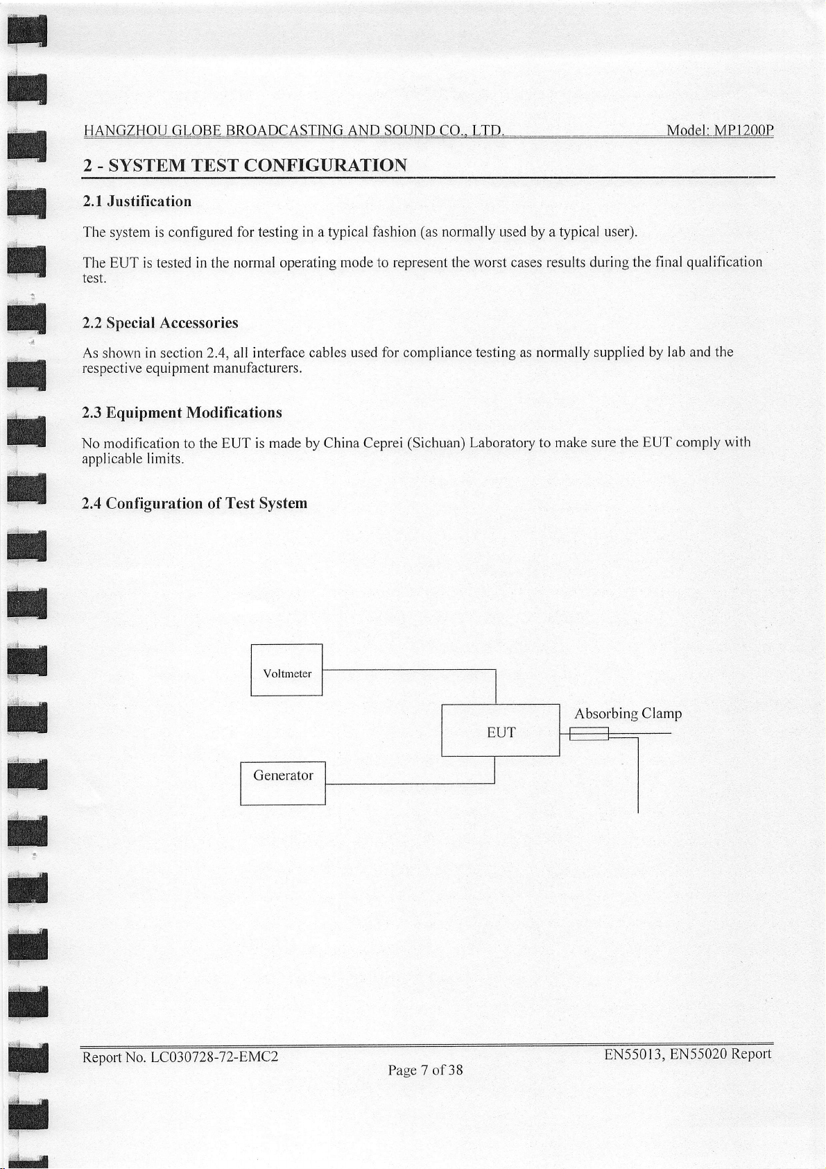
2 - SYSTEM TBST CONFIGURATION
2.1
Justification
Tlre
system is configured
The
test.
2.2 Special
As slrown in section
respective equiprnent manufacturers.
2.3 Equipment Modifications
No
applicable limits.
2.4 Conliguration of
is tested in the normal operating
EUT
Accessories
modification to the EUT
for
testing
2.4,
interface cables used
all
is made by China Ceprei
Test System
in a typical
fashion
mode to represent the worst cases results
(as
norrnally Lrsed by a typical
for compliance testing as normally supplied
(SichLran)
Laboratory to make
user).
during the final
by lab and
sure the EUT
qualification
the
comply witt
ll
;r
T
il
fl
fl
Voltmeter
Absorbing
Clamp
t
tl
g
Reoort
No. LCO 3 07
28-7 2-EMCL
Page
7 of38
EN550
I 3,
EN55020
Report
Page 9
I
n
i
HANGZIOIIGtOBL
BRQADeASIINOANDS-OII{DeO*LTD.=*-
,,--,------Msdel._Mll200P
;
:,
f
n
n
H
:,
t
i
Ir
f
t
3 - MAINS TBRMINAL
Measurement Uncertainfy
3.1
All nreasurernents
uncertainties are
Based on NIS 81,
conducted emissions measllrement
3.2 EUT Setup
Tlre measurement is
procedure.
The
A 230 V ACl50Hz
Tlre test is
EMI Receiver Setup
3.3
Dr,rring the
The testing setup
spacing
perforrned
conduction test, the EMI
Frequency.................
Start
F1equency.................
Stop
Sweep Speed
IF Bandwidth
Step..............
involve ceftain levels of
EMI receiver,
The Treatment of Uncertainty
performed
power
at the
peripherals
source
between the
DISTURBANCB VOLTAGE TEST DATA
cable loss, and LISN.
at China Ceprei
in the
is according
provides
worst case
uncertainties, especially in field of CEPRI.
in EMC Measurements,
(Sichuan)
screened enclosure, using
to the standard EN55013,
is l0 cm.
power
to the EUT.
as shorvn in the attached
testing receiver is set with the
.................
................. 9
Laboratory is
the same setup
photographs.
150 kHz
30 MHz
Auto
1W9
The factors contributingto
the best estimate
+2.0
dB.
per EN550l 3: 2001
as
shown
following configurations:
kFIz
k4z
in Attachment
of the uncertainty of
any
measuremellt
A.
il
l
I|
T
;,
tl
H
H
T
5
\
3.4 Test Procedure
During
the
installation
All data
fourid to be marginal
The EUT is testecl with
for final
3.5 Summary
According
OI:
Report
the mains tenninal disturbance
LISN. Maximizing
combination.
is recorded
test data recorded
to the data
-5.20
dBuV at 0.15
No. LC03
in
(within
of Test
0728-7 2-EMC2
procedure
peak
the
the
Results
in section
detection
-4
dBpV
power
in the
MHz
voltage test, the
is also
table listed
3.6, tlre
of Disturbance
performed
mode.
of specified
is found to
line
EUT
in section
complied with
power
on the highest
the worst
3.6.1.
Mains
at
of38
readings
Quasi-peak
limitations).
produce
Voltage
Page 8
cord of EUT
emissions to
Quasi-peak
results. Therefore,
the limit requirement,
Terminal
is connected
are only
readings
ensure EUT
performed
rvith the worst
t9 the aLrxiliary
compliance
an emission
when
are distinguished
configuration
this
EN550l
with a
nargin
3, EN55020
of
outlet
using,all
is
"Qp".
is used
reading
Repor"t
H
ri
Page 10

I
t
I
I
;'
t
t
;
HALIGZ,I]O-ILALIBE
;
3.6 Mains Terminal
Test Data of Disturbance Voltase
3.6.I
Mn rils TpR[arN.lL
FreQqency
0.l s
24.23
6.41
5.95
29.81
20.49
3.6.2 Disturbance Voltage
Appendix C contains a
BROADCASTING
Disturbance Voltage
Dar.q.
Test
nelNCE
Curve at
l)tsru
Tnsr
,
60.80
41.50
31.50
37.20
36.10
30.70
copy of disturbance
S
AND
Test Data
at Mains Terminal,
VoLTAGE
QP
QP
QP
QP
QP
QP
lVlains Terminal
voltage
test clrrve at
---*-M-ode]l]ILLI2OOP
0.15 - 30 NIFIz.
EN5SOI3iCISPR
ii'1li
66.00
60.00
60.00
60.00 50.00
60.00
60.00 50.00
mains tenninal.
-.ii-i
56.00
50.00
50.00
50.00
13
-5.20
-l8.50
-22.50
-22.80
-23.90
-29.30
il
f
il
t
H
T
il
t
t
T
T
Reoort
No. LC030728-7
2-EMC2
Page 9 of38
EN5501 3,
EN55020
Report
Page 11

f
n
n
H
t
rl
T
T
t
HANGZH AITGIABI
4 - DISTURBANCE
4.1 Test Procedure
The test is
0.8 m of height
shall be stleiched in
pennit
measured, with its current transformer towards the eqr-ripment
the
disturbance
Any other lead less than tl-rat to be measured shall either
or fltted with ferrite rings to attenuate RF currents
stretclred away fi'om
All conriectors not used
rnanner
tenlination
4.2
Summary
According to
matgin
performed
above the
the necessary
power
representative
shall be screened.
of
the data in section 4.3,Ihe EUT, MPl200P complies
for Audio
BRAADeASUNGAN,DIa
POWER TEST
in screened
floor
a straight horizontal line
adjustment
on the lead.
connected unit in a direction
tlre
shall be
of use. If the
Test
Results
& Video Associated
room, The
least 0.8 rn
and at
positior,
of its
left un-terminated.
leads
are screened and
Equipment,
U"{D eO*UD--
DATA
associated equipment
frorn other objects
for
a length sufficlent
for
tuning. Tlie absorbing clamp
under test, so as to measure a
be disconnected, if mechanically
which may affect the measurement results.
perpendicular
All connectors havins a connected lead shall be terminated in a
rrormally
with the worst n"targin
----_-Model-MP12,008
under test is
and from any
to accommodaie the absorbing clamp and to
to the
terniinated in
with the EN55013/CISPR l3 Disturbance
placed
is
direction of the
reading of:
on a non-metallic table of
person.
placed
a screened
The lead to be measured
around
and
the lead
quantity proportional
functionally
Sucli a
lead to
be measured.
unit, then the
to be
lead
possible,
shall be
Power
to
;
t
t
il
il
It
t
n
-12.0
dBpW
4.3 Disturbance
4.3.1 Test
Data for Disturbance Power at Power Line
Pownn LrNn DTSTURBANCE
Frequencl,
IMFIz
71.1 36.1
41 .0
215.1 23.3
284.0 22.8
235.6 20.2
at7l.7
Power Test Data
MHz of Disturbance Power
'',Amplitude'
33.6
at Power Line
at Normal Mode. 30 - 300 MHz
Powpn Tnsr Dlr,q EN5sOI3/CISPR 13
llli
Qp
Qp
Qp
Qp
Qp
I) mitll
48.1
46.3
53.5
s4.7
53.9
,
.dB
-12.0
-12.1
-30.2
-31.9
-33.7
t
H
tl
Report
No. LC030728-1 2-EMC2
Page l0
of38
EN55013,
EN55020 Report
Page 12
l
n
n
H
t
i!
h
t
n
h
F
F
H
r
t
r
n
T
T
HANGZHOLGI0BE-B&OAD-C,{SING
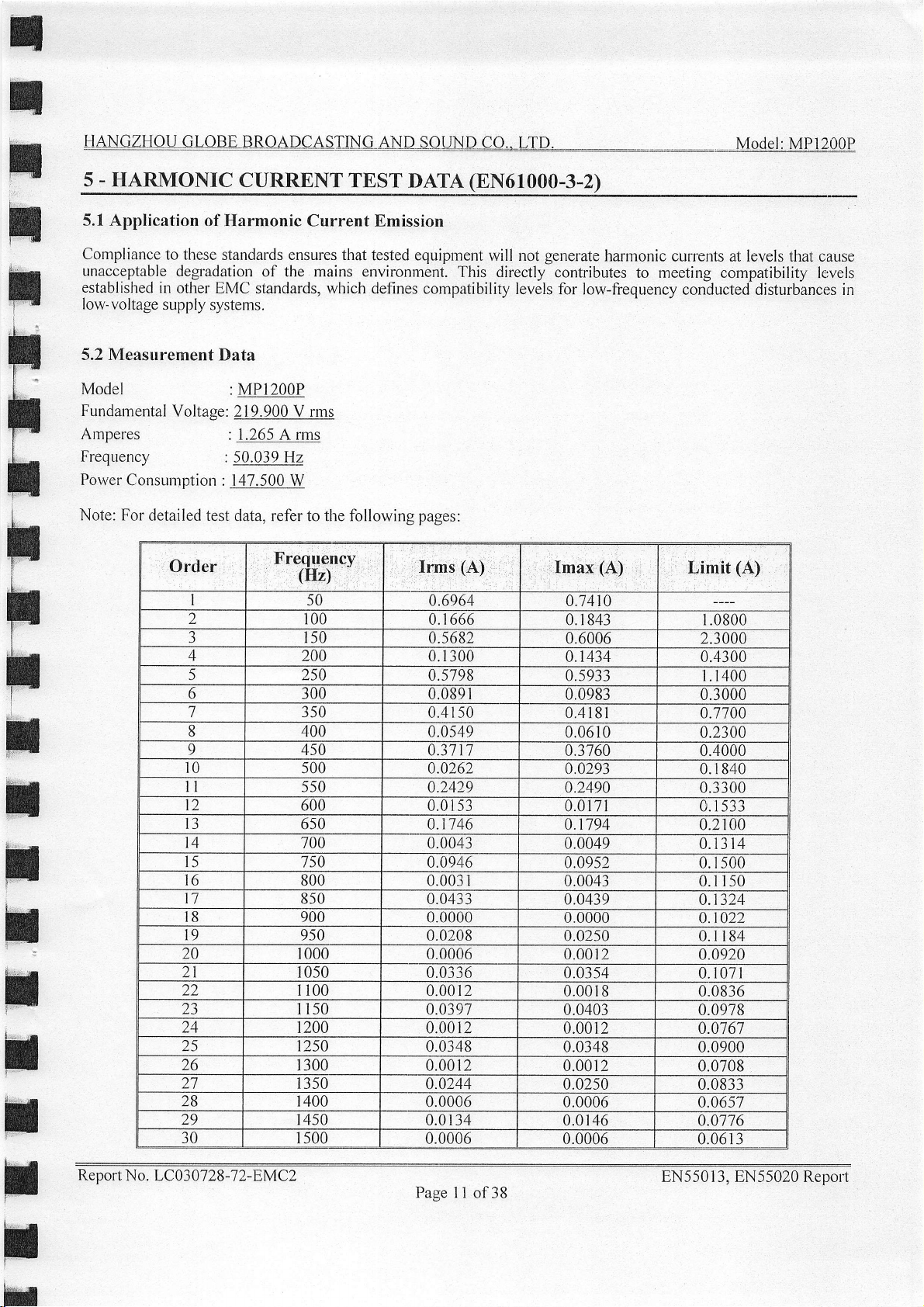
s - HARMONTC
5.1 Application
Cornpliance
unacceptable
established
low- voltage
5.2 Measurement
Model
Fundamental
Amperes
Frequency
Power
Note: For
to these standards ensures that
degladation
in
other EMC
supply
Voltase: 219.900 V rms
Consuntption
detailed test
Order
2
J
4
5
6 300
7 350
8
o
4
o
1
8 900
o
20
)l
22
23
24
25 250
lo
21
28
29 450
30
CURRENT
of
Harmonic Current Bmission
of the mains environrnent.
standards,
systems.
Data
: MP1200P
: 1.265 A rms
: 50.039 Hz
: 147.500
data, refer to the following
Frequency
0
2
J
5
wlrich
W
(Hz)
50
100
r50
200 0.1
250
400
450
500 0.0262
550
600
650
700
750 0.0946
800
850
950
000
050
r00
r50
200
300 0.00 r 2
350
400 0.0006
500 0.0006
AND,S-O
TEST
tesled equipment
defines cornpatibility
pAT4
pages:
Irms
@N!1000-3-2)
will not
This
directly contributes
(A)
0.6964
0.1666
0.5682
300
0.5798
0.089 r .09tJ:i
0.41 s0 0.41Bl
0.054e
0.37 t]
0.2429
0.0 t 53 0.0171
0.1146 0.r194
0.0043 0.0049
0.003 r
0.0433
0.0000
0.0208
0.0006
0.0336
r 2
0.00
0.0397
0.0012
0.0348
0.0244
0.0134
generate
levels
for low-frequency
Imax
0.7410
0. I 843 1.0800
0.6006 2.3000
0.1434 0.4300
0.5933 1.r400
0.0610
0.3760 0.4000
0.0293
0.2490
0.09s2
0.0043 0 150
0.0439
0.0000 0 o22
0.0250 0 184
0.0012 0.0920
0.0354
0.001
0.0403 0.0978
0.0012 0.0767
0.0348
0.0012
0.0250 0.0833
0.0006
0.0146 0.0716
0.0006
--Mqdel
_
harmonic
(A)
8 0.0836
currents at levels that cause
to meeting compatibility
conducted disturbances in
Limit
(A)
U.JUUU
0.7700
0.2300
0. I 840
0.3300
-533
0.2100
0 314
0 500
0 324
0 071
0.0900
0.0708
0.0657
0.06 r 3
MP,1200P
.
lervels
t
il
Report N
o. LC03 07 28
-1
}-EMCZ
8N5501 3, 8N55020 Report
Page I 1 of38
Page 13

H
n
n
n
;
t"
t
lI
;
t
;
5.3 Test
The
EUT
The EUT
ctrrenl
Test
3l
)L
JJ
)+
35
36
37
38
39
40
Results
is subjected
measured
and
photographs
setup
550
600
650
100
750
800
850
900
950
2000
to the hannonics
neutral
values
currenl,
of the
presented
current
harntonic,s
shall be
in Appendix
0.01 l0
0.0000
0.0128
0.0006
0.0 r40
0.0006
0.0128
0.0006
0.0098
0.0000
test
required
compared
0.0116
0.0006
0.0134
0.0006
0.0140
0.0006
0.0 r
0.0012
0.0098
0.0006
by EN6l000-3-2:1995.
component.g
ivilh
A.
of the
the Iimits giien
34
iwut
0.0726
0.0575
0.0682
0.0s41
0.0643
0.0511
0.0608
0.0484
4.0577
0.0460
currenl,
in ,section
incluclins
line
5.2.
t
I
T
T
T
H
il
u
t
tl
H
Report
No. LC03
07 28
-7
2-EMC2
Page l2 of38
8N5501
3, EN55020 Reporl
Page 14

I
ll
;
n
n
I
I
t
i
n
I
r
il
I
il
il
HANGZHOU
6 - VOLTAGE FLUCTUATIONS
6.1
Application of
Compliance to these
tlrat cause
levels
disturbances
6.2 Measurement
Model
Fundarnental
Amperes
Frequency
Power
Note: For
established
Consr:motion
IIOLE-BRO-ALCASING
Voltage Fluctuations and Flick
standards ensures that tested equipment
unacceptable degradation
in other EMC standards.
in low-voltage supply
Data
:MPl200P
Voltage:
detailed test data, refer to the fbllowing
219.900 V nns
: 1.763 A rrns
:49.914 Hz
:215.000
I 0.012
2 0.074
J
+
6 0.072 0.000 0.000
1
8
9
l0 0,081 0.000 0.000 0.020 0.000
II
12 0.071 0.000 0.000
W
ri
: i il:
the
of
systems.
0.075
0.073 0,000
0.077 0.000 0.000
0.072
0.078 0.012
0.080 0.000
0.074 0.015
jllDS-oWD
ANp FLICK
Test
main envirouurent. This
which defines compatibilitv
pages:
0.00 0.000 0.0r0 0.000
0.000 0.000 0.020
0.000 0.000 0.020 0.000
0.008 0.000 0.020 0.000
LID=-,-
eO-*
TEST
will not
0.000 0.020 0.000
0.000 0.020 0.000
0.000 0.020 0.000
0.000 0.020 0.000
pATA
generate
directly contributes
0.020 0.000
0.020
0.0r0
-**---- -Modal:MPl2!0P
(8N61000-3-3)
flickers and voltage change
levels for low-fi'ecluencv
I
_
le,vels
at
to meeting compatibility
conducted
0.000
0.000
0.000
t
f
H
il
t
tl
6.3 Test Results
The EUT is subjected to the voltage fluctuatiorrs and flick test required by EN6l000-3-3: 1995.
The EUT
and
neutral current, shall
Test
setup
Report No. LC03
measured values
photographs
-1
2-EMC2
0728
of
the
be compared with
presented
te.st of the
flick
in Appendix A.
input
limit,s
lhe
Page l3 of38
current,
given
in
including
,seclion 6.2.
8N5501
line current
3, EN55020 Report
Page 15

tl
n
I
,
il
i
t
ia
t
n
H
HANGZHOUGLOBEBROADCASTINGAND-S-OINDIO*LlD--------::**-Msdcl:MPL200P
;
I
t
t
n
il
H
H
IMMUI{ITY
PARTII
TEST DATA
AND
RESULTS
H
t
t
H
Report No.
LC03 0728
-1
}-EMC}
Page l4
EN55013, EN55020 Reporl
of38
Page 16

;
n
il
;
F
l:
;
tI
;
t
;
tt
1 . GBNERAL
1.1 Product
The
HANGZHOU
referred
1.2
The following
behalf of
2002,ElecI,romagnetic
Industry.
Currently, EN55020:
applicability
l. Electrostatic
2.
3. Electrical
4.
Data
requires
to in this
Objective
HANGZHOU
The objective
of the
RF-electrornagnetic
Inimunity
have been
the following
INFORMATION
Description
GLOBE BROADCASTING
report is a PROFESSIONAL
Declaration
Compatibility Generic
of the manufacturer is
2002
EUT, these four
discharge immunity
fast
transient/Burst
to inducted
collected, reduced,
as specific
for Equiprnent
of Conformity
GLOBE
references seven
field immunity
voltage of mains
BROADCASTING
tests are chosen.
(ESD)
(EFT/B)
analyzed
and
performance
Under
AND
POWER
report of an
Imrnunity
to demonstrate
specific Ratified
test
in accordance
test in
accordance
immr,rnity
terminal/audio
within
criteria:
(EUT)
Test
SOUND
AMPLIFIER.
Information
AND
Standard, Part
with EN61000-4-3.
test in
input/output
this report in
CO., LTD.,
Technology
SOUND CO.. LTD. in
compliance
Standard
with EN6l000-4-2.
accordance with
model MPI200P
Equipment
accordance wiih EN55020:
l: Residential,
with EN55020:2002.
tests to be
terminal
accordance
performed.
8N61000-4-4.
in accordance with 8N61000-4-6.
with EN55020: 2002. Immunity
orthe
"EUT"
device
Commercial and Light
is prepared
Due to the
standard
as
on
t
FI
T
r
H
n
H
t
A.
The apparatus
specifies
manufacturer
B. The
C. Temporary loss
In
order to dernonstrate
necessary
Maintenance
rnaybe
circuit
1.3 Test
All nreasurements
Generic Immunity
by
China Ceprei
steps to ensure
result in lowering
board layor,rt changes,
Methodology
apparatus
does not need
some
minimal performance is
or
data is
autoriraticdlly reset
of compliance is the
contained in this report
Standard
(Sichuan)
shall continue
minimum perfo-rmhnrie
some
permiss-ible
as a
shall continue to operate
to function at nonnal
perrnitted
of function is allowed.
or can be manually
compliance, the manufacturer
that the
the immunity
equipment complies
responsibility of the manufacturer.
different line filter, different
Part I:
Compliance
Residential, Commercial
to operate
loss of
performance
defindd
should be clrecked to
are conducted
Laboratory.
intended
as
lev_el. The performince
performance.
as intended
by the manufacture.
Operation
resiored
or a contracted
with the appropriate
power
with EN55020: 2002,Electromagnetic
durinq
after the
levels during
of the EUT may
by operation
ensure cornpliance
supply,
and Light Industry.
and after
level may be
test. This indicates that
the test. but must recover.
Nd change in operating
of th"e coritrols.
laboratory
Any modification of the
harnessing
makes measurements and takes the
teclinical standards.
has been maintained
All measurements are
the
stop as
and/or
test. The
long as
I/O cable
manufacturer
specified by the
state or l-oss
it is
product
Compatibility.
the EUT
Again
either
which
(i.e., printed
changes, etc.).
performed
:r
FI
Renort
No. LC03
0728-7
2-EMC2
8N55013, EN55020 Repofi
Page l5 of38
Page 17

I
n
;
H
t
l
t
l-
I
t
;
I
1.4
Test
The
Open
data
is located
1.5
Bquipment
1.6
Local
Facilify
Area
Test
in the
Under
Manufacturer
GLOBE
Support
Equipment
site
used
No.60
Wen
Test (EUT)
by China
Ming Dong
General
POWER
List
and Details
Ceprei
(Sichuan)
Road,
Longquanyi
Description
Description
PROFESSIONAL
AMPLIFIER
Compliance
Laboratory
Chengdu
MPI2OOP
610100
Model
to
collect
p.
R.
,:UoOsLltEUO0S
immulity
China.
Serial
measurement
Number
No
t
I
t
I
t
I
I
:
I
n
I
I
n
il
I
l.T
lnterface
Manufacturer
YONGMING
HONGXING
(No)
Ports
and
Cable
Description,
Aurdio
Cable
Shielded
Shielded
Cable
Cable
Cabling
Description
Generator
Voltage
4
List
and
,.,Length
1.5
Meter
O
Load
Details
(M)
x2
1.0
1.2
Model
YM-1000
HX r
840-5s
No
FromlPort:
Generator
Netr,vork
Voltrneter
Serial
No
To/Port
EUT
EUT
EUT
Number
No
No
t
U
T
t
tl
Report
No.
LC0307
28-l
2-EMC2
Page
l6
of38
EN55013,
8N55020
Report
Page 18

.
2
SYSTBM
2.1
Justification
The
whole
The
EUT is
2.2
Special
As
shown in
from
the respective
2.3
Equipment
No
modification
2.4
Test
Setup Block
TEST
system
is
configured
tested in the
Accessories
section 2.4,
equipment
Modifications
to the
EUT
CONFIGURATION
for
testing in
normal
all interface
Diagram
operating
manufacturers.
is made
mode
cables
by CEPREI
a typical
used
fashion (as
to
represent
for compliance
LAB
to make
norrnally
worst-case
testing
sure
results
are
the EUT
used
by
a typical
during the
normally
comply
supplied
with
user).
qualification
final
by GLOBE
applicable
limits.
test.
and
Signal
Generator
Report
No.
LC03
0728
-1
2-EMC2
Page
l7 of38
8N550
13, 8N55020
Report
Page 19

T
n
n
H
f
T
:l
H
I
I
-
3
MEASURBMENT
3.1
Electrostatic
A Sanki
discharge
accordance
3.2
$
Research
EMCO
accordance
field probe
3.3
A Fluke
at any phase
clanrp
3.4 Equipment
ESD-320
rnodes
RF-electromagnetic
Giga
1r9rli9!,6061A
V-2980
3143
with tlre
and
Electrical
E.F-.TB
in accordance
tester
to 8_[Y
with
the EN6l000-4-2
directional
biconilo_g.a1t9nna
field ntonitor,
Fast
Generator
angle
with.
Test
INSTR"UMENTATION
Discharge
signal generator
EN6l000-4-3
Transient/Burst
{esPecl_19_t]11{c
with the
Table
Immunity
is
used for
31g:ir
Field
8401 tester
all
discharg*e-
basic EMC publication.
Immunity
coupler are
to
obtain the
basic EM^C pirblication-
model,
EN6l000-4-4:1995
Test
System
testing.
and aArnplifier
FP2000
Immunity
is
It
is capable
modes
to
Test
System
used
used for
provide
to
required
anO t-li,tZOOO,
alltesting.
l!n9
^voltage.wave
basic
of applying
t s kV
in
bbltr"poiitive
Research
a sigral
electroinagnetic
Test
System
EMC
50W10004 power
at
the
The freld
respectively
It is
form
publication.
is
capable
ancl
to attached"ca6les
Electrostatic
and
approfriate powbr
fielil
arthe
monirored
according
of applying
discharges
negative
arnplifier
pdsition
by Uotti
t|"
bNAf
fast transients
via
in
polirities.
and
of the EUT
of AmplifiirResear,;h
a capacitive
both conract
Ttris
is in
with a Amplifier
freqLren.t
OO0-4-3
i;;
in
stanclards.
to
the AC li'e
C*pt,ng
t
n
I
I
T
H
tl
EN6l000-4-2:1995
centitneters
approximarely
refe.rence plane
placed
is
The
EUT
Y:.'li:gl9qr-rpling
EN6l000-4.-4
reference
certtirnete
table
over a
3.5
Instrument
All
rest
manufacturer's
Extensive
equipment
unavoidable
possible
gro,und
on the
and attached
plane
rs
above a ground
ground
equip.ment
engineering
calibration
levelof uncertainty.
generator
test
specifies
reference plane
l0 centimeters
in
conformance
table
and.connected
Plane (VCP).ground_ed
specily
specifi
that
and that
reference
Calibration
is-regularly
cati
efforts
schedules.
that
a table.top^EUT
and
thai floor-morrnted'equiprnent
above
a.ground.plane.
with this
cables
are isolated
a tabletop
floor,mounted.equip"l.-"1_qtf.]l
plane.
plane
checked
ons.
have
However,_the
These include
output
unceftainties.
requirement-
ground
to the
fiom
on the
EUT
be
During
been made
the EN6l
in conforntance
to
ensure
shall
be
DLrringthe'tests,
Fortibletop
plane
via
thid
metal
ground
placed
to enslrre
application
inaccuracies
plane
on i non-condricting
be
000-4-4
with
performances
that
test
this
placed
sheet
placed
of radio
on a non-conductingtable
shall
the
EUT
eqr-ripm
a meial
by
0.5 rnillirneters
through
on
ancl EN6l000-4-6
requirement.
are
clata
reliability
frequency
in
antenna factors,
ent,
dtrdp
with two
the
same
table
an Tnsulating
maintained
througli
be placed"on
positioned
is
1'.6
a
configurarion
B0 cefrtimeters
teits,
fiells
chamber
an insulating
by 0.8 meter
4i0 k
Ohms
thick
insulating
support
in
Quality
and uoitages
approximateTy
gUi"'is
ilie
accorclance
irnpErfections
above
which
sLlpport
overag6rria
me"tal
resistors in
material.
as ii'
the HCp
above a
Control
gt.luna
positioried
with the
and regular
are
not wifirout
and
is B0
sheet
series.
A
is used.
l0
on a
(I{Cp)
an
t
hl
H
Report
No.
LC0307
2B-l 2-EMC2
Page
I B of38
EN550l
3,
EN55020
Reporl
Page 20

HANQHOU-GIO-B-E-BIROdDCASILLG
,AND-SO-UND
eO
-tD-
..--
*--
voaet
: u-P
t zoop
3.6 Test
*
Statement
performed
been
Equipment
Sanki
FlLrke
Giga
tronics
Qianfeng
No
No
Qianfeng
of
Traceability:
using
suitable
List
Electrostatic
Discharge
Synthesized RF
signal
Power
RC Network
MSF
Millivolt
China Ceprei
standards
Tester
H.t,.l.B
Generator
generator
Arnplifier
Network
rneter
traceable
ESD-320 0329501
840 I
606r
QF3B06
KD-917
TT-1000
QF228r
(Sichuan)
to the
A
Compliance
CHINA
SCIENTIFIC
0695048
5 I 30304
No
550327
I 0350K
92028
Laboratory
MEASUREMENT
C
certifies
611t 104
6lt7l04
4t11t04
4t17t04
Bl1sl04
B/15/04
Bl1st04
that all calibration
INSTITUTE.
has
Report
No. LC030728-7
2-EMC2
Page l9
of38
EN5501
3,
EN55020
Report
Page 21

n
t
t
H
il
H
H
ll
il
t
4.
TEST
4.1
EUT
The
EUT
grouncl
cables
simulate
4.2
Application
The
test
test
Ievels
applied
surfbces
Iocation
4.3
Application
The
ele-ctrornagnetic
1000
MFIz
modulated
F:,ltg",F l9l{.qe1gra1ing
Iteld
ts.tlren
created
PROCEDURES
and
Cable
and
any other peripherals
plane
with
the.insLrlating
to
be
connected
a
typical
is
conducted
are
to the
on
is recordedl
gsi[8^a
field
are
noted
installation
of
Electrostatic
in
set and
conductive
the comnuter.
manually
discharges
of Electromagnetic
field is
power.level
Strengti
increased
before
Placement
to
the following
surface
is
continuing.
are
located
support
available
When
established
directed
antenna..lf
ports
so faias
necessary
until the error
to
Discharge
order:
for
the different
of the
computer
a discharge-occurs
Field
at the.
at the EUT.
an error
at the
center
fo^r floor-standing
of the
unit
practical.
be
Air
to
obtain
and
Immunit"v
Discharge,
test
in
which the
and
Irnrnunity
front
eclge
a 3lrolt/meter
'fhe
is
detected,
begins
devices.
tliat
modes
an error
Test
of the
test
performed
is
the freld
to occur.
ofthe
table
placement
the
Test
Direct
are
set
EUT
is caused,
EUT.
and
This
fbr tabletop
The
standarcls
of
1',nii
the
Contact
appropriately.
ls'enitoseAjuna
is
threshold
Discharge.
the
The
frequency
aOZ
amptitLidrof
with
the most
reduced
f"fre Etectrosiuti.
tjrpe
until
1evel,
devices
reqr.rire
Uong
of .*&,
range
susceptible
the
the frequency
and in
that intercolnecting
ana t6e
The
error is
attached
Electrostatic
all seams
aiscnarge
is
swept from
u I kHz
not r.p.ututG,
the
Ofti[uige
unO
sine
side
of the
unb
center
cables
Discharge
cotitrot
ieu.f
g0
wave
EUT
G iribt
ofthe
is-
ana
to
th.
n
t
n
I|
il
il
t
il
4.4
Application
The,EUT
applicable.
longer
table and
electrical
4.5
Tlre
loldecl
the
a rnaximurn
4.6
No
is._arranged
(N9ter
in length
is
ear1h.
Application
EUT,is placed
and
connected
audio
inpr-rt
Deviations
deviations
of Electrical
for?ower,Line
The
I/O coupling
than
3 meters.).,A.1neta_!
connected
and
at
30MHz.
from
to the
of Immunity
at a
in the
otttput
from
the
EN55020:
Fast
earth
to
distance
shorlest
terminals
Standard
2002
Transienfs
Coupling
test
uiing
ground
by a2.6
Inducfed
of
possible.way.to.the
bf the
are made
rneteri ground
0.1 m
above
EUT
Immunity
and
for t/O
a capacitive
piane2.4
Voltage
the
.slrall
when performing
Test
Line
Coupling
clamp
is
rneteis
rod.
of
center
coupling
be o1'coaxial
The
Mains
of
metal
the
Ay Z.O
ground
Terminal/Audio
unit.'The
type
tests
through
perdrmed
meter
rod
plate
(2
c'able
with
u trund$ii'"ledance
described
a capacitive
Jn the I7O
placed
is
is ioirnect"Jto
m x I
sLrpplying
in
interface
between
Input/Output
m). The
the
this report.
clamp,
it.r"
mains
inducted
ioUt.r
the
i"ri
oiio
where
floor
A"if ity,t
Terminal
lead
that are
and the
shal
voltage
iiTn
r
be
to
u,
il
t
Report
No.
LC03
0728-7 2-EMC2
Page
20
of38
EN550l
3, 8N55020
Report
Page 22

r
n
H
n
5.
TBST
5.1
Environmental
DATA
__-]!Lode.l-MPl_200I
Conditions
n
n
il
fl
t
I
t
x
5.2
Electrostatic
Table
Tcst Points
IltlT Front
Side
EtiT'l'op
Sidc
EtiT
Side
EtJ'l'l,el't
Side
EtlT
Right
Sidc
Discharge
1: Electrostatic
-,:
KV
ru
ii::i:. i ;i:ri
Back
Discharge
i:, :,
j:1,
:
kVii
,,,t-'
' +::i{li;
. it
'
,,1
iiiiliiilifi
iiiiiiil!a,ri:
ij
.'.i';:l
Temperature:
Humidity:
ATM
Pressure:
Immunity
,..'iii
:.kV+{kv
i !,: iii:t:
tllflii:i
,jt,
ffi
friiiiiii
brir,iiit
"l
ffi
i$i-ljrt{jil
r"l
:ii
;.
ii?tlI
l;:::,
,]
ilti,'li:tfi
irj
Test
Immunity
i.,u,
KV
'
I
,'
lil!i.li.t:
fiil,ili
iii*'}14
lt
$f.$$
ri#
lli,,.u
irffi
.tf*r
kYi':,t
,'{.i
ui I liiiir ri
iii
t$rirri
(dir
Discharge)
Test
Levels
l,l"8.l
l:kY.ii
B
B
B
B B
B
24"C
65%
l033rnb
r+l?;F,
il.oi
l"l,Lori
IiVr
'itltY'i;
ffi
B
r*liiii'::
't.',
r
,rla:r
B
B
B
t
,,,'
ffi
j;;iffi
ffi
i;t!:ji13i}:jii
it'i
lirlir
',ffi
t;,lt.,i
'
tit"
+!2.5i
,,,iVl,1i
ii
,
;:,.";l
;;;i
'ritfit:..
;"''..;,
';;.
;;..r
l-;;,1
lLi15i
rkV,l
i;"i1
:
I
f;,:r
iti'ri4l
ilffi
,.
1,1
+.{5,,
r*vi;
',.1
t,t
tl
:,."
!.
.liriitlli:|j:ilr
;,;
+2Q
;tr!,"tt
,
kVrr:
rti,ii
il."iii:!;1:i
iit:\ii,liir
ffi
iiiti.
ti irl
,:''':'i
:i,=i
.,,:,,
i'ijii'n;i
riiiii1I
,;j.r
:.,:#K
,l
i,,
i,
t
lril
,1
n
r|
tf
t
il
t
il
t
Table
EtiT
Report
No.
2:
Electrostatic
Etl'f Front
Side
-top
ti,tiT
Side
EtlT
Back
Side
BtlT
Left
Side
Righr
Side
LC03
-)
iu"
ii+r:llrliri
lii.li
-
!,.:l
:.:'l
07 28-1
2-EMC2
Discharge
it.
.,Hi
llt\li
,ik-rr4t:l
L,fffi;j
,Bri*i,!{t
i:nilii;:l;rl:
itffi
Immunity (Direct
i4i
fi,6:'
.kti
kv'i
B
B
B
B
iiiiii
riiii$$
?lfirrirt:
B B
B
B
rfi
B
tt
B
.
l,kV,:l
iri$iii:
iiffl
f,,',;
l
':'-i
.;;
t:.1
Contact)
Test
Levels
#r
ilill;
iiq.i
ikx{,j
liiiii;ili
i:
i
:iir.l
.',
,.
rrll
Page2l
',,ll{l'
;lrkVj
;,
lir;il$,tl
lin4r;+
ru
:ffi
ii-aii:il
;iti;$
o{'38
, .:I
,,119
:l:kv
t'".
t;.
r'l
',j
lrL?;5:
r;j;livrlt
;',1'
.:
i
'
.
ti,;'
$i'B
illrihv:ir
;;.::;'
i
i'i
'j
',.,
,
I'i
+ii,"'
t'i,t''i
il{i.tLlr':'i
irlir
ikVl;i
,;tt't
;
='.
.
':
''"'
i
,r liv:
;;..';
*'i:li
!.rtlitrli!
.r.li,.'i-U
.{l':
t
i;,t
'.
I,t':'
,,,!?t)
!,kV
!
;:i
:.t20.
iitV;,
f:
jii:1::jlirjitli
, i.rtiii.j
i
i*t
il.
,,'l
,j
''t
n
Page 23

n
rl
t
fl
fl
t
il
f
n
t
HANCZI{OU-GI8B-E-B-R-O-ADCASIMG-
5.3 Radiation Immunity
Inrmunity
Frequency
(MHz)
1.56
15.48
34.72
51.23 127.00
r24.25
5.4 Electrical
.. I : i-:,
::li:i'
'
'
'-
I
Power
to ambient
Fast
"!'li
Supply
electromagnetic
Test Level
',
(dBuV):
Transient/Burst Immunfrty Test
iffi
'::'=.i
L
N
AND SOI
field in th':
127.00
128.00
r27.00
138.00
'r,'".
i,:,.j:
iirl,ri
ri;j;4i:jl:;l
NDeO*
frequency
;:-.f:
r."y.l
it:nl ',,'
::: :
''i
ITD---
range 0.15
timit Level
(dBuV),,,
>
>
>
=
>
.liiri.i:'::-i
: I . ..:'.i.li
t'
i
----,,-ModqLMPL2O0E
MHz to l50MHz
125.00 Passed
I25.00
125.00
125.00 Passed
125.00 Passed
iliib',6
:,rii.:,tl:l:
rt|:i:
B B
B B
.: li
Risults
Passed
Passed
t'.;i,li1
riflrllrfliililld
ijiltililiilft
,t:,
illllill ili
titj!.it
T
rl
I
t
il
il
n
5.5 Conduction Immunity
Immunity
to RF voltage of mains terminal in the freqLrency range 0.l5
Mains
Terminal
Frequency
,
,(MHz)
15.60
48.20
64.50
86.s0
150.00
MHz to 150
Limit
Level
,(dBuV)
>
130.00 r
>
120.00 122.00 Passed
>
120.00 t24.00 Passed
>
120.00
>
I 10.00
,
Lbvel
Test
(dBuV)
:
33.00
t23.00 Passed
121 .00
'
MHz
Results
Passed
Passed
t
t
i
Renort No. LC03 0728
-7
2-EMC2
Page22
of 38
EN5501 3, EN55020
Report
Page 24

I
r
n
rf
f
t
r|
t
f
t
t
il
HAMGZH,O-U-GLO-BLBROADeASTILIG-AND
Immunity
Immunity
OUTPUT
OUTPUT
to RF
Input
Terminal
INPUT A
INPUT
Output
Terminal
B
to
RF voltage
A
B
voltage of input
Frequency
(MHz)
7.40
65.40
95.60
t2s.60
1.40
65.40
95.60
125.60
of output
Frequency
(MHz)
7.40
65.40
95.60
t25.60
1.40
65.40
95.60
125.60
audio terminal
audio terminal
S-O-UND
in
the frequency
Limit'Level
I
(dBuV)
=
108.t9
>
120.00
=
120.00
>
I14.38
>
108.19
>
120.00
>
120.00
=
I 14.38
in
Limit tevel
(dBuV)
>
108.19
>
120.00
>
120.00
>
I14.38
=
l0B.l9
=
120.00
=
120.00
>
ll4.3B
eO-*LiID-------
range
Test
,fdBuV)
the frequency
r,
range
Test Level
,
(dBu\n::
0.15
Level
r 13,00
122.00
125.00
r20.00
r r
5.00
t23.00
124.00
120.00
0.1 5 MHz
1 1 r.00
124.00
123.00
r 18.00
I 16.00
r23.00
122.00
I 19.00
---
MHz to
to I 50 MHz
*-IaoOsLlt4pl20Oil
150 MHz
Results
Passed
Passed
Passed
Passed
Passed
Passed
Passed
Passed
Results
Passed
Passed
Passed
Passed
Passed
Passed
Passed
Passed
t
I
I
il
t
t
il
fl
U:250V
Note:
Reoort
No. LC030728-7
A
B
C
-----
Performance
-----
Performance
-----
Performance
2-EMC2
Criteria
Criteria B
Criteria C
A
as stated in
as stated in
as stated in
Page 23
of38
Section 1.2
Section I
Section 1.2
.2 of this rebort
of
of this rebort
this
report
8N55013, EN55020 Report
Page 25

tl
n
t
n
il
i,,
H
i
i
fr
I|
t
I
I
ti
-
6
PRODUCT
6.1
CE
Mark
Text
is
Black
or
backing
6.2 Proposed
and
slrall
Label
LABELING
Label
Specification
white
in color
be affixed
Location
and is
Ieft
at a
conspicuous
on EUT
EUT
Rear
justified.
Labels
location
on the
printed
are
gUt
in
indelible
or
silk-screened
ink on
onto
FF
LE
View
permanent
the EUT.
adhesive
t
il
r
fl
il
I
I
t
il
I
I
t
I
il
I
I
I
I
Report
No.
LC03
07 2B-7
Z-EMC2
Page
24
of38
8N550
I
3, 8N5,5020
Reporr
il
Page 26

;
T
n
:l
n
n
n
I
HAU
t
t
r
;
H
t
I
fr
APPENDTX
A * TEST
PHOTOGRAPHS
il
I
n
I
f,
H
Report
N o. LC03
07
28
-7
T-EMCZ
Page 25 of38
8N5501 3, EN55020
Report
Page 27

Disturbance
Test
Voltage
Setup
Mains
at
View
Terminal
Report
No. LC0301
28-7 }EMC2
Page
26
of38
8N550 I 3, EN55020
Report
Page 28

HANCZHOU
CTOEE BROADCA
Disturbance Power
Test
Setup View
Report No.
LC03 07 28
-l
z-Eil c2
Page27
8N55013, EN55020 Repoft
of38
Page 29

Harmonic
Current
Test
Setup View
Report No. LC03 07 28-l
2-EMC2
Page 28
8N5501 3, 8N55020 Report
of38
Page 30

Voltage
Fluctuations
and Flick
Test
Setup
View
Report
No. LC030728-7
2-EMC2
Page 29
of38
EN5501 3, EN55020
Report
Page 31

t
t
il
n
t
rl
T
T
TF
T
Elecfrostatic
Discharge
Immunity
il
13
t
I
il
rl
t
rl
-ffi
*ryT
il
r!
Report
No. LC03
07 28
-7
2-EMC2
Page
30
of38
EN5501 3,
EN55020
Report
Page 32

Ambient
Electromagnetic
Field
Immunify
Test
Setup
View
+ii,:tili
:t:
r:1it;r
.i,:r,':
rtl;::;ji
l
Reoort
LC03 07 28-7 2-EMC2
No.
Page 31
of38
EN550l
3, EN55020 Report
Page 33

OI-rND
CO., LTD.
Model:trltptzoop
Electrical
Fast Transients
Immunity
Test
Setup
View
t
tr\=
wt
Ir#
-n\-"
[
il
t
fi1
%b
%
ryn.
dfrlii!
t
#k#"
ry
*
tu,
Report
No. LC13O7 2B-7 2-EMC2
Page
32 of38
8N550
1 3, EN55020
Report
Page 34

Inducted
Audio
Signal
Voltage
Immunity
Input/Output
to Mains
Terminals
Terminal/
Test
Setup
View
Report
No. LC03 0728-7
2-EMC2
Page 33
of38
EN550
1 3, 8N55020
Report
Page 35

rffi
tr
H
li
n
t
tr
r
n
n
,LfD,__._
_
_ModeLMplZOO_B
n
t
rE
tr
t
r
r
rl
APPBNDIX
B
*
BUT
PHOTOGRAPHS
il
rl
I
r
I
i
Report
No.
LC03
07 28-1
2-EMC2
Page
34 of38
EN5501
3, EN55020
Reporl
Page 36

rL{NGZHOU
GLOBE BROAD
EUT Front
View
Reoort No. LC03 07 28
-1
2-EMC2
Page 35
8N550 1 3, EN55020 Report
of38
Page 37

ffi
rW
rn
rT
rn
t
n
il
T
t
EUT
Rear
View
t
tr
t
t
t
il
tr
r$
r3
t
Report
No.
LC,0301
28-7
2-EMC,2
Page 36 of38
EN5501
3, EN55020 Report
Page 38

H
m
I
;
H
Il
;
:
;
;
t
#
l.
F
I
F
:
I
f,
I
;
t
APPENDIX
TEST
CURVE
-
C
DTSTURBAI{CE
AT
MAINS
VOLTAGE
TERMINAI.,
r
i
t
f,
I
il
Report
No.
LC0307 2B-7
2-EMC2
Page 37
of38
EN550l
3, EN55020
Reporl
Page 39

L
ffi*t
r
lY:]
--l
1r
.;
J
-t
...J
.l*.,1.tr,'
-J
I
tt---l
'r'l
:tr l-l-t
i:il
,l
4rrl
,i .,
,.1:-r
.
fit,
i
1,,,,
;i,
i'
'
-.;L:;'
q
I
N
--l
--l
,i,,1
l,tl
uTi
il
*r1
I
I
__l
-,-l
T;I
l--l
-;
,:jji:17:::.:tl
'".
*-1
*-1
*__i
I
..._,f
'l
-t
J#+J
I
I'ff]#Jtr*r1
j:
,,
,,.r
J#f tt tl
Report
No. LC03 07
28-7 2-EMC2
Page 38
of38
EN5501 3, EN55020
Report
 Loading...