

Page 1

X-TRAIL
BETRIEBSANLEITUNG
Page 2

Foreword
Welcome to the growing family of new NISSAN owners. This vehicle is delivered to you with confidence. It is produced using the latest techniques and strict quality
control.
This manual was prepared to help you understand the operation and maintenance of your vehicle so that you may enjoy many kilometres (miles) of driving pleasure.
Please read through this manual before operating your vehicle.
A separate Warranty Information & Maintenance Booklet explains in detail the warranty coverage that applies to your vehicle.
Your NISSAN dealer knows your vehicle best. When you require any service or have any questions, your NISSAN dealer will be glad to assist you with the extensive
resources available for you.
IMPORTANT SAFETY INFORMATION
REMINDERS FOR SAFETY!
Follow these important driving rules to help ensure a safe and complete trip for
you and your passengers!
NEVER drive under the influence of alcohol or drugs.
•
ALWAYS observe posted speed limits and never drive too fast for condi-
•
tions.
ALWAYS use your seat belts and appropriate child restraint systems.
•
Preteen children should be seated in the rear seat.
ALWAYS provide information about the proper use of vehicle safety fea-
•
tures to all occupants of the vehicle.
ALWAYS review this Owner’s Manual for important safety information.
•
WHEN READING THE MANUAL
This manual includes information for all options available on this model. Therefore, you may find some information that does not apply to your vehicle.
Throughout this manual, some illustrations may only show the layout for LeftHand Drive (LHD) models. For Right-Hand Drive (RHD) models, the illustrated
shape and location of some components may differ.
All information, specifications and illustrations in this manual are those in effect
at the time of printing. NISSAN reserves the right to change specifications or
designs at any time without notice and without obligation.
MODIFICATION OF YOUR VEHICLE
This vehicle should not be modified. Modifications could affect its performance,
safety or durability, and may even violate governmental regulations. In addition,
damage or performance problems resulting from modifications may not be covered under NISSAN warranties.
READ FIRST — THEN DRIVE SAFELY
Before driving your vehicle, read this Owner’s Manual carefully. This will ensure
familiarity with controls and maintenance requirements, assisting you in the safe
operation of your vehicle.
Throughout this manual the following symbols and words are used:
WARNING
Indicates the presence of a hazard that could cause death or serious personal injury. To avoid or reduce the risk, the procedures described must be
followed precisely.
CAUTION
Indicates the presence ofa hazard that could cause minor or moderateper-
sonal injury, or damage to your vehicle. To avoid or reduce the risk, the procedures described must be followed carefully.
NOTE
Indicates additional helpful information.
Page 3
The Blue Citizenship symbol indicates environmentally friendly information and
best practices.
This symbol means “Do not do this” or “Do not let this happen”.
Arrows in an illustration that are similar to these point to the front of the vehicle.
Arrows in an illustration that are similar to these indicate movement or action.
<>:
Chevrons or angle brackets are used to indicate texts on controls like buttons or
switches inside or on the vehicle.
Air bag warning labels:
“NEVER use a rearward facing child restraint on a seat protected by an ACTIVE
AIRBAG in front of it, DEATH or SERIOUS INJURY to the CHILD can occur.”
Be sure to read the “Airbag warning labels” description in the Safety section of
this manual; and the “Airbag label” description at the end of this manual.
ON-PAVEMENT AND OFF-ROAD DRIVING (4WD models)
This vehicle will handle and manoeuvre differently from an ordinary passenger
vehicle, because it hasa higher centre of gravity. As with other vehicles with features of this type, failure to operate this vehicle correctly may result in loss of
control or an accident.
Be sure to read “On-pavement and off-road driving precautions” and “Fourwheel drive (4WD)” in the “5. Starting and driving” section of this manual.
Arrows in an illustration that are similar to these call attention to an item in the
illustration.
[]:
Square brackets are used to indicate messages, keys, or items displayed on a
screen.
Page 4

BATTERY DISPOSAL
CAUTION
An improperly disposed battery can harm the environment. Always confirm
local regulations for battery disposal.
Examples of the batteries that the vehicle contains:
Vehicle battery
•
Remote controller battery (for Intelligent Key and/or Remote keyless entry
•
system)
Tyre Pressure Monitoring System (TPMS) sensor battery
•
Remote controller battery (for Mobile Entertainment system)
•
If in doubt, contact your local authority, or a NISSAN dealer, or a qualified workshop for advice on disposal.
Bluetooth® is a trademark owned by Bluetooth SIG, Inc.
m
and licensed to Visteon Corporation and Robert Bosch
GmbH.
m
iPod® is a trademark of Apple Inc.
Page 5
Contents
Illustrated table of contents
0
Safety — seats, seat belts and supplemental restraint
system
Instruments and controls
Pre-driving checks and adjustments
Display screen, heater and air conditioner, and audio
system
Starting and driving
In case of emergency
Appearance and care
Maintenance and do-it-yourself
Technical information
Index
1
2
3
4
5
6
7
8
9
10
Page 6

Page 7

0 Illustrated table of contentsIllustrated table of contents
Seats, seat belts and Supplemental Restraint
System (SRS).......................................................... 0-2
Exterior front............................................................ 0-3
Exterior rear............................................................. 0-4
Passenger compartment .......................................... 0-5
Cockpit ................................................................... 0-6
Left-Hand Drive (LHD) model.............................. 0-6
Right-Hand Drive (RHD) model........................... 0-8
Instrument panel ...................................................... 0-10
Left-Hand Drive (LHD) model.............................. 0-10
Right-Hand Drive (RHD) model........................... 0-11
Meters and gauges.................................................. 0-12
Engine compartment................................................ 0-13
QR25DE engine model....................................... 0-14
MR16DDT engine model .................................... 0-14
MR20DD engine model ...................................... 0-15
R9M engine model ............................................. 0-16
Page 8
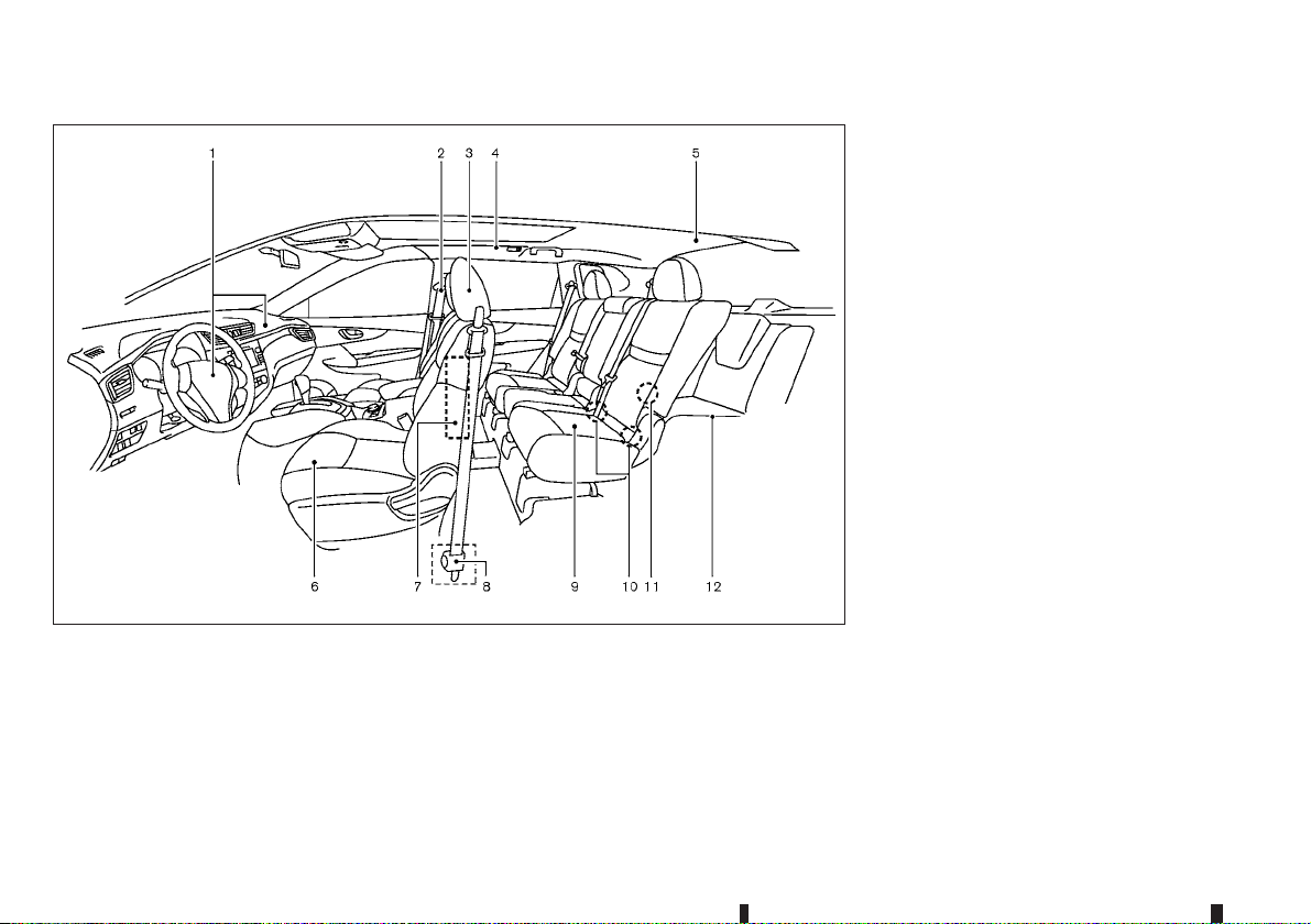
SEATS, SEAT BELTS AND SUPPLEMENTAL RESTRAINT SYSTEM (SRS)
JVC0589X
Child restraint anchor point (for top tether
11.
strap child restraint) (P. 1-23)
Third row seats* (P. 1-7)
12.
*: where fitted
Supplemental front-impact air bags (P. 1-30)
1.
Seat belts (P. 1-10)
2.
Head restraints (P. 1-8)
3.
Supplemental curtain side-impact air bags
4.
(P. 1-30)
Child restraint anchor point (for top tether
5.
strap child restraint)* (P. 1-15)
0-2 Illustrated table of contents
Front seats (P. 1-2)
6.
Supplemental side-impact air bags (P. 1-30)
7.
Pre-tensioner seat belt system (P. 1-38)
8.
Second row seats (P. 1-5)
9.
— Child restraints (P. 1-15)
ISOFIX child restraint system (for second row
10.
seats) (P. 1-22)
Page 9
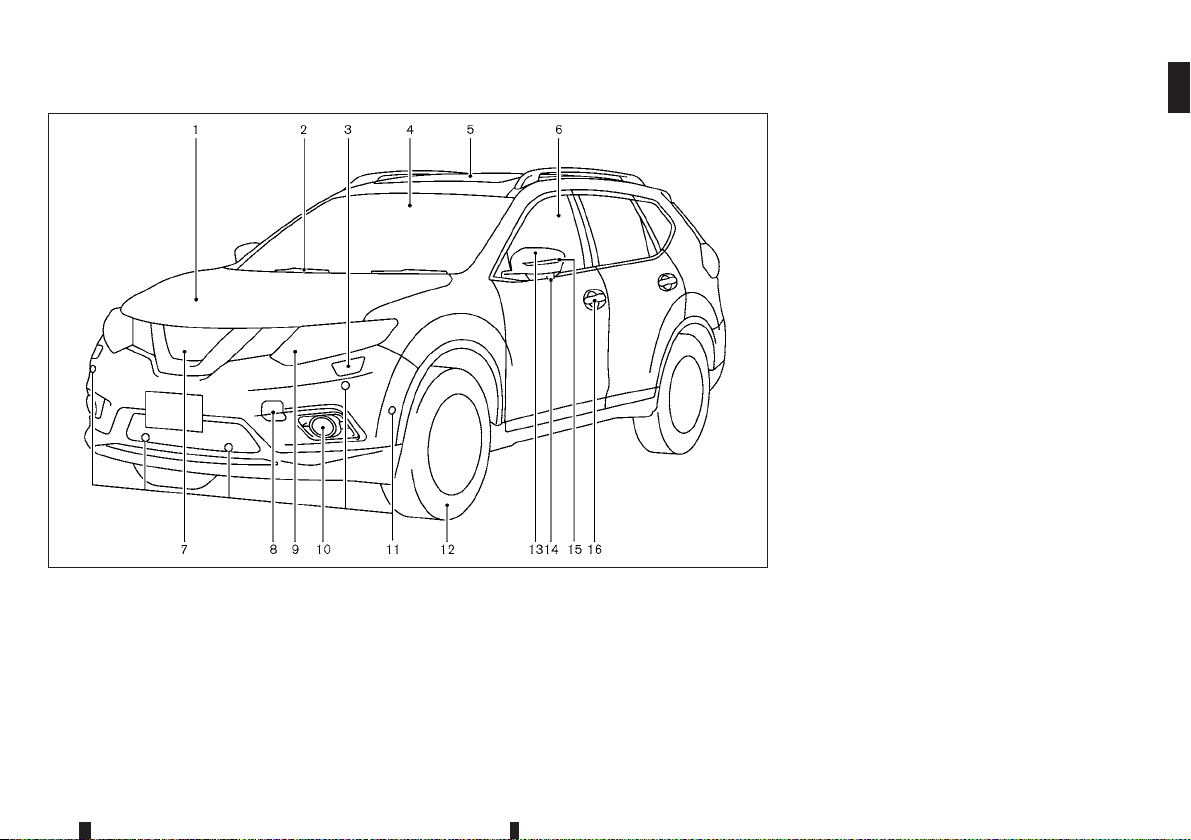
EXTERIOR FRONT
JVC0642X
Parking sensor system* (P. 5-49)
11.
— Park Assist (PA)* (P. 4-14)
Tyres
12.
— Tyres and wheels (P. 8-34, 9-7)
— Flat tyre (P. 6-2)
— Tyre placard (P. 9-9)
Outside mirrors (P. 3-30)
13.
Side view camera* (P. 4-6)
14.
Side turn signal light (P. 2-41)
15.
Doors
16.
— Keys (P. 3-2)
— Door locks (P. 3-4)
— Intelligent Key system* (P. 3-9)
— Remote keyless entry system* (P. 3-7)
— Security system (P. 3-20)
*: where fitted
Engine bonnet (P. 3-23)
1.
Windscreen wiper and washer
2.
— Switch operation (P. 2-43)
— Window washer fluid (P. 8-17)
Headlight cleaner* (P. 2-41)
3.
Front camera* (P. 4-6, 2-33, 5-36)
4.
Sunroof* (P. 2-49)
5.
Power windows (P. 2-47)
6.
Front view camera* (P. 4-6)
7.
Recovery hook (P. 6-13)
8.
Headlights and turn signal lights (P. 2-35)
9.
Fog lights* (P. 2-42)
10.
Illustrated table of contents 0-3
Page 10
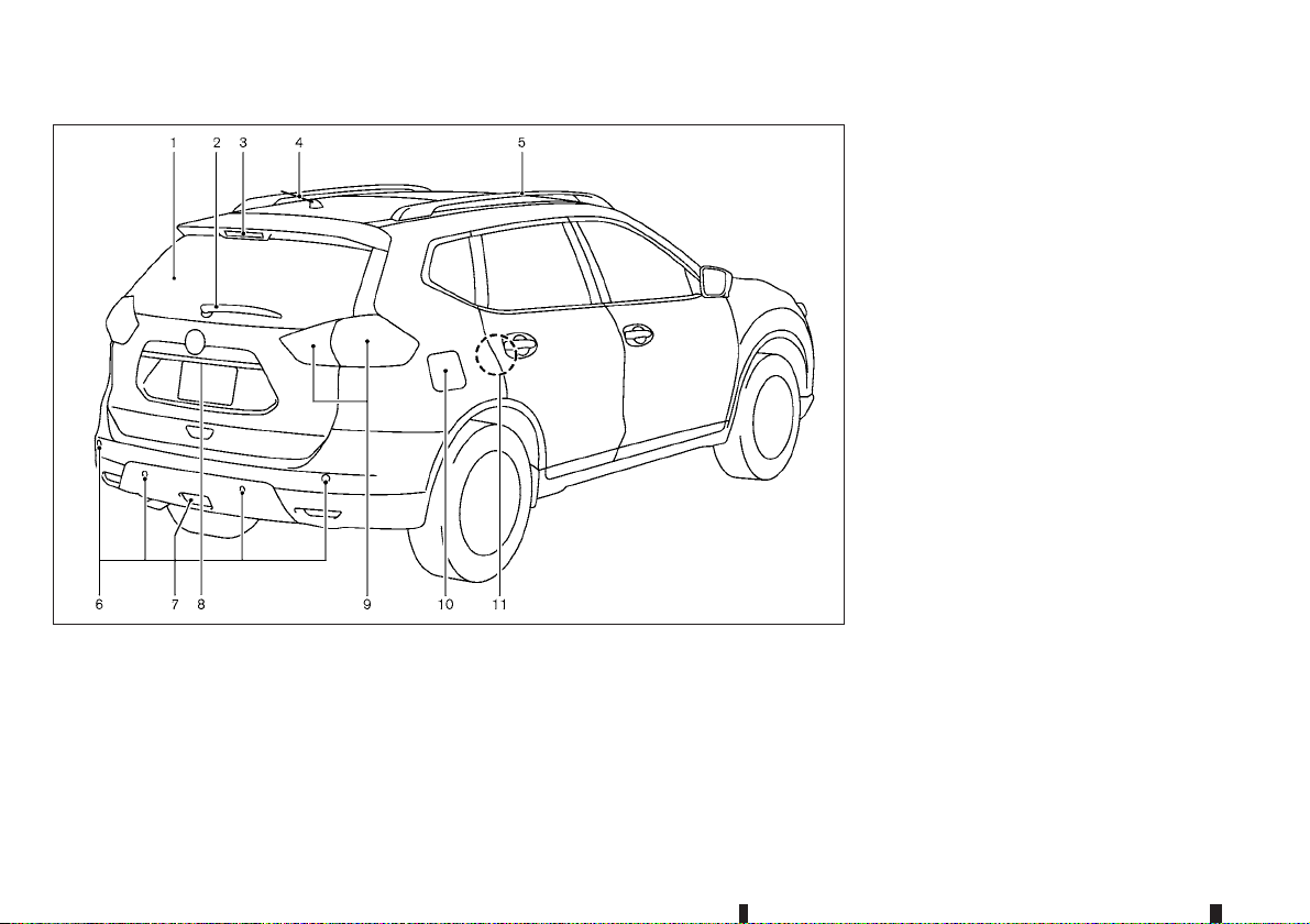
EXTERIOR REAR
JVC0599X
— Remote keyless entry system* (P. 3-7)
— Rear view camera* (P. 4-6)
Rear combination light (P. 8-25)
9.
Fuel-filler lid (P. 3-28)
10.
Child safety rear door locks (P. 3-6)
11.
*: where fitted
Rear window defogger (P. 2-46)
1.
Rear window wiper and washer
2.
— Switch operation (P. 2-45)
— Window washer fluid (P. 8-17)
High-mounted stop light
3.
— Bulb replacement (P. 8-26)
Antenna (P. 4-38)
4.
0-4 Illustrated table of contents
Roof rail* (P. 2-57)
5.
Parking sensor system* (P. 5-49)
6.
— Park Assist (PA)* (P. 4-14)
Rear fog light (P. 2-42)
7.
Back door (P. 3-24)
8.
— Intelligent Key system* (P. 3-9)
Page 11
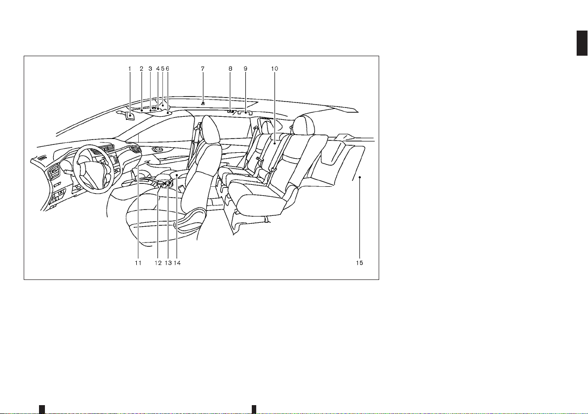
PASSENGER COMPARTMENT
JVC0654X
Door armrest
11.
— Power window switch (P. 2-47)
— Power door lock switch* (P. 2-6)
— Outside rearview mirror remote control
switch (Driver’s side) (P. 3-30)
Front cup holders (P. 2-53)
12.
Heated seat switch* (P. 1-5)
13.
Console box (P. 2-52)
14.
Luggage room
15.
— Storage (P. 2-54)
— Luggage hooks (P. 2-54)
— Tonneau cover* (P. 2-57)
— Power outlet (P. 2-51)
— Spare tyre (P. 6-2)
*: where fitted
Inside rearview mirror (P. 3-29)
1.
Sunglasses holder (P. 2-52)
2.
Front map lights (P. 2-58)
3.
— Microphone (P. 4-56, P. 4-63)
Sunroof* (P. 2-49)
4.
Cancel switch for ultrasonic and tilt sensors*
5.
(P. 3-21)
Sun visors (P. 2-58, 3-31)
6.
Room light* (P. 2-59)
7.
Rear personal lights* (P. 2-59)
8.
Coat hook (Driver’s side) (P. 2-56)
9.
Rear armrest (Second row seats) (P. 1-7)
10.
— Rear cup holders (P. 2-53)
Illustrated table of contents 0-5
Page 12

COCKPIT
LEFT-HAND DRIVE (LHD) MODEL
Instrument brightness control (P. 2-3)
1.
TRIP RESET switch (P. 2-2)
2.
Headlight and turn signal switch (P. 2-35)/Fog
3.
light switch* (P. 2-42)
Steering-wheel-mounted controls (left side)
4.
— Audio control* (P. 4-54 or Navigation
system **)
— Vehicle information display control (P. 2-14)
— Bluetooth® Hands-Free Phone System
(without navigation)* (P. 4-56)
— Bluetooth® Hands-Free Phone System
(with navigation)* (P. 4-63)
NIC2485
Steering wheel (P. 3-29)
5.
— Horn (P. 2-47)
Wiper and washer switch (P. 2-43)
6.
Hazard indicator flasher switch (P. 6-2)
7.
Steering-wheel-mounted controls (right side)
8.
— Cruise control switches* (P. 5-41)
— Speed limiter switches* (P. 5-39)
— Bluetooth® Hands-Free Phone System
(without navigation)* (P. 4-56)
— Bluetooth® Hands-Free Phone System
(with navigation)* (P. 4-63)
Shift lever
9.
— Xtronic Continuously Variable Transmission
(CVT) (P. 5-13)
— Manual Transmission (MT) (P. 5-16)
Electronic Stability Programme (ESP) OFF
10.
switch (P. 5-27)
Headlight aiming control switch* (P. 2-37)
11.
ECO switch* (P. 5-45)
12.
Headlight cleaner switch* (P. 2-41)
13.
Parking sensor system OFF switch* (P. 5-50)
14.
Power back door switch* (P. 3-24)
15.
Stop/Start OFF switch* (P. 5-21)
16.
Power back door main switch* (P. 3-24)
17.
Push-button ignition switch (model with Intel-
18.
ligent Key system)* (P. 5-8)
Ignition switch (model without Intelligent Key
19.
system)* (P. 5-7)
0-6 Illustrated table of contents
Page 13

Parking brake (P. 3-31)
20.
Hill descent control switch* (P. 5-32)
21.
Four-Wheel Drive (4WD) mode switch*
22.
(P. 5-22)
where fitted
*:
See the separate Navigation System Owner’s
**:
Manual (where fitted).
Illustrated table of contents 0-7
Page 14

RIGHT-HAND DRIVE (RHD) MODEL
Hill descent control switch* (P. 5-32)
1.
Steering-wheel-mounted controls (left side)
2.
— Audio control* (P. 4-54 or Navigation
system **)
— Vehicle information display control (P. 2-14)
— Bluetooth® Hands-Free Phone System
(without navigation)* (P. 4-56)
— Bluetooth® Hands-Free Phone System
(with navigation)* (P. 4-63)
Hazard indicator flasher switch (P. 6-2)
3.
Headlight and turn signal switch (P. 2-35)/Fog
4.
light switch* (P. 2-42)
Push-button ignition switch (model with Intel-
5.
ligent Key system)* (P. 5-8)
NIC2486
Steering-wheel-mounted controls (right side)
6.
— Cruise control switches* (P. 5-41)
— Speed limiter switches* (P. 5-39)
— Bluetooth® Hands-Free Phone System
(without navigation)* (P. 4-56)
— Bluetooth® Hands-Free Phone System
(with navigation)* (P. 4-63)
Wiper and washer switch (P. 2-43)
7.
Power back door main switch* (P. 3-24)
8.
Power back door switch* (P. 3-24)
9.
Instrument brightness control (P. 2-3)
10.
TRIP RESET switch (P. 2-2)
11.
Electronic Stability Programme (ESP) OFF
12.
switch (P. 5-27)
Four-Wheel Drive (4WD) mode switch*
13.
(P. 5-22)
Shift lever
14.
— Xtronic Continuously Variable Transmission
(CVT) (P. 5-13)
— Manual Transmission (MT) (P. 5-16)
Parking brake (Switch type)* (P. 3-31)
15.
Steering wheel (P. 3-29)
16.
— Horn (P. 2-47)
Ignition switch (model without Intelligent Key
17.
system)* (P. 5-7)
Stop/Start switch* (P. 5-21)
18.
Parking sensor system OFF switch* (P. 5-50)
19.
ECO switch* (P. 5-45)
20.
0-8 Illustrated table of contents
Page 15

Headlight aiming control switch* (P. 2-37)
21.
where fitted
*:
See the separate Navigation System Owner’s
**:
Manual (where fitted).
Illustrated table of contents 0-9
Page 16
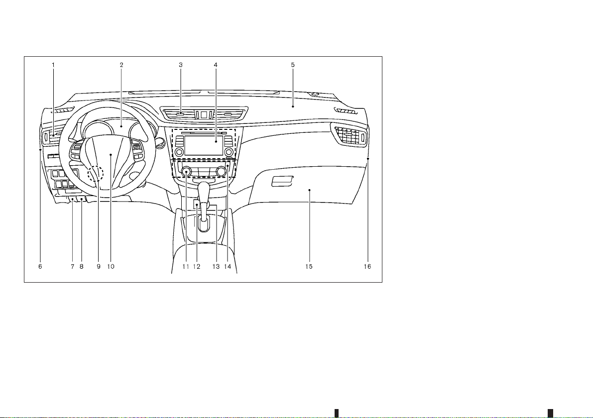
INSTRUMENT PANEL
JVC0663X
Bonnet release handle (P. 3-23)
8.
Steering wheel lock lever (P. 3-29)
9.
Driver’s front-impact air bag (P. 1-30)/Horn
10.
(P. 2-47)
Heater/air conditioner control (P. 4-24)
11.
Auxiliary (AUX) input jack* (P. 4-54) and USB
12.
connection port* (P. 4-53)
Power outlet (P. 2-51)
13.
Defogger switch (P. 2-46)/Heated windscreen
14.
button (P. 4-30)
Glove box (P. 2-52)
15.
Fuse box cover* (P. 8-21)
16.
where fitted
*:
See the separate Navigation System Owner’s
**:
Manual (where fitted).
LEFT-HAND DRIVE (LHD) MODEL
Side vent (P. 4-23)
1.
Meters and gauges (P. 2-2)/Clock (P. 4-40)
2.
Centre vent (P. 4-23)
3.
Audio system* (P. 4-30) or Navigation
4.
system**
— Around view monitor* (P. 4-6)
0-10 Illustrated table of contents
— Bluetooth® Hands-Free Phone System
(without navigation)* (P. 4-56)
— Bluetooth® Hands-Free Phone System
(with navigation)* (P. 4-63)
Passenger’s front-impact air bag (P. 1-30)
5.
Fuse box cover (P. 8-21)
6.
Fuel-filler lid release handle (P. 3-28)
7.
Page 17
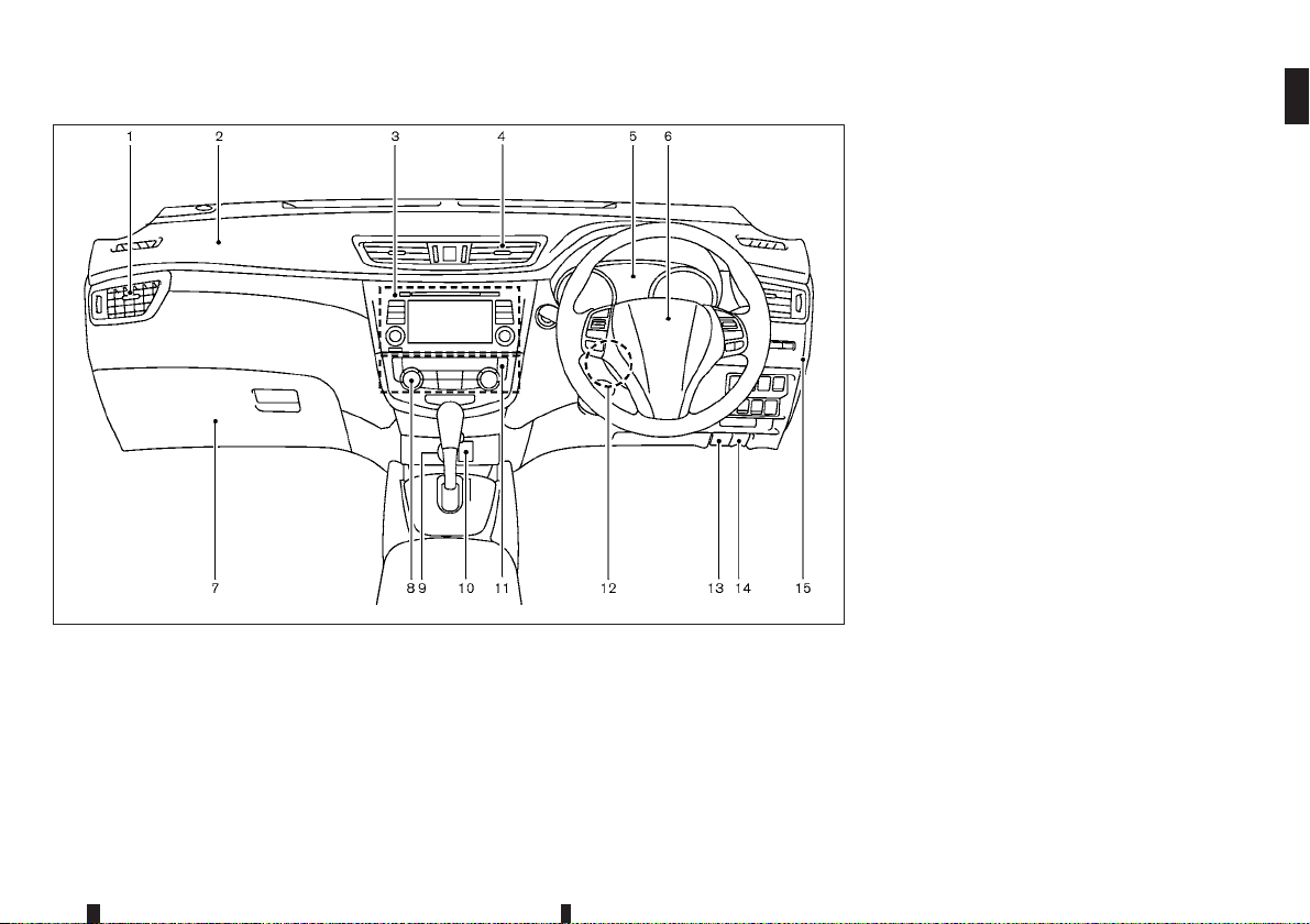
JVC0662X
Glove box (P. 2-52)
7.
— Fuse box (P. 8-21)
Heater/air conditioner control (P. 4-24)
8.
Power outlet (P. 2-51)
9.
Auxiliary (AUX) input jack* (P. 4-54) and USB
10.
connection port* (P. 4-53)
Defogger switch (P. 2-46)/Heated windscreen
11.
button (P. 4-30)
Steering wheel lock lever (P. 3-29)
12.
Bonnet release handle (P. 3-23)
13.
Fuel-filler lid release handle (P. 3-28)
14.
Fuse box cover* (P. 8-21)
15.
where fitted
*:
See the separate Navigation System Owner’s
**:
Manual (where fitted).
RIGHT-HAND DRIVE (RHD) MODEL
Side vent (P. 4-23)
1.
Passenger’s front-impact air bag (P. 1-30)
2.
Audio system* (P. 4-30) or Navigation
3.
system**
— Around view monitor* (P. 4-6)
— Bluetooth® Hands-Free Phone System
(without navigation)* (P. 4-56)
— Bluetooth® Hands-Free Phone System
(with navigation)* (P. 4-63)
Centre vent (P. 4-23)
4.
Meters and gauges (P. 2-2)/Clock (P. 4-40)
5.
Driver’s front-impact air bag (P. 1-30)/Horn
6.
(P. 2-47)
Illustrated table of contents 0-11
Page 18
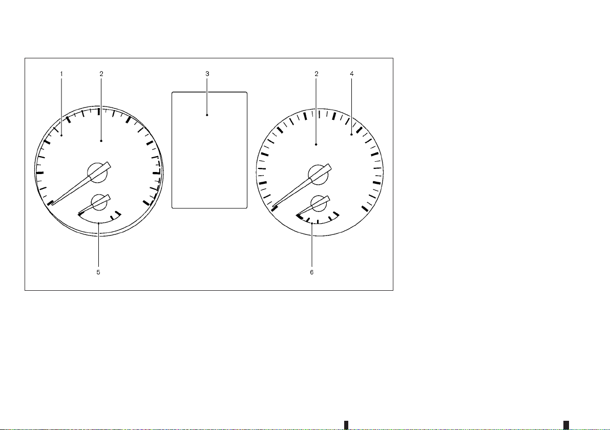
METERS AND GAUGES
JVC0581X
Tachometer (P. 2-2)
1.
Warning/indicator lights (P. 2-5)
2.
Vehicle information display (P. 2-14)
3.
— Odometer/twin trip odometer (P. 2-2)
Speedometer (P. 2-2)
4.
Engine coolant temperature gauge (P. 2-3)
5.
0-12 Illustrated table of contents
Fuel gauge (P. 2-3)
6.
Page 19

ENGINE COMPARTMENT
QR25DE ENGINE MODEL
Engine coolant reservoir (P. 8-5)
1.
Engine oil filler cap (P. 8-7)
2.
Brake fluid reservoir (P. 8-14)
3.
Air cleaner (P. 8-16)
4.
Battery (P. 8-18)
5.
Window washer fluid reservoir (P. 8-17)
6.
Engine drive belts (P. 8-11)
7.
Engine oil dipstick (P. 8-7)
8.
Radiator cap (P. 8-5)
9.
— Vehicle overheat (P. 6-11)
Fuse/fusible link box (P. 8-21)
10.
NIC2487
Illustrated table of contents 0-13
Page 20
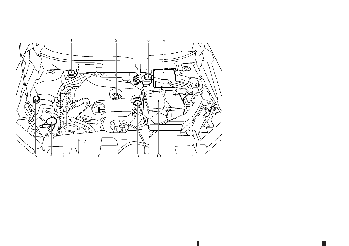
MR16DDT ENGINE MODEL
Brake and clutch fluid reservoir (P. 8-14)
1.
— RHD model
Engine oil filler cap (P. 8-7)
2.
Brake and clutch fluid reservoir (P. 8-14)
3.
— LHD model
Air cleaner (P. 8-16)
4.
Engine coolant reservoir (P. 8-5)
5.
Window washer fluid reservoir (P. 8-17)
6.
Engine drive belts (P. 8-11)
7.
Engine oil dipstick (P. 8-7)
8.
Radiator cap (P. 8-5)
9.
— Vehicle overheat (P. 6-11)
JVC0813X
Battery (P. 8-18)
10.
Fuse/fusible link box (P. 8-21)
11.
0-14 Illustrated table of contents
Page 21

MR20DD ENGINE MODEL
Engine coolant reservoir (P. 8-5)
1.
Brake and clutch* fluid reservoir (P. 8-14)
2.
Air cleaner (P. 8-16)
3.
Fuse/fusible link box (P. 8-21)
4.
Window washer fluid reservoir (P. 8-17)
5.
Engine drive belts (P. 8-11)
6.
Radiator cap (P. 8-5)
7.
— Vehicle overheat (P. 6-11)
Engine oil dipstick (P. 8-7)
8.
Engine oil filler cap (P. 8-7)
9.
Battery (P. 8-18)
10.
*: For Manual Transmission (MT) Model
NIC2488
Illustrated table of contents 0-15
Page 22
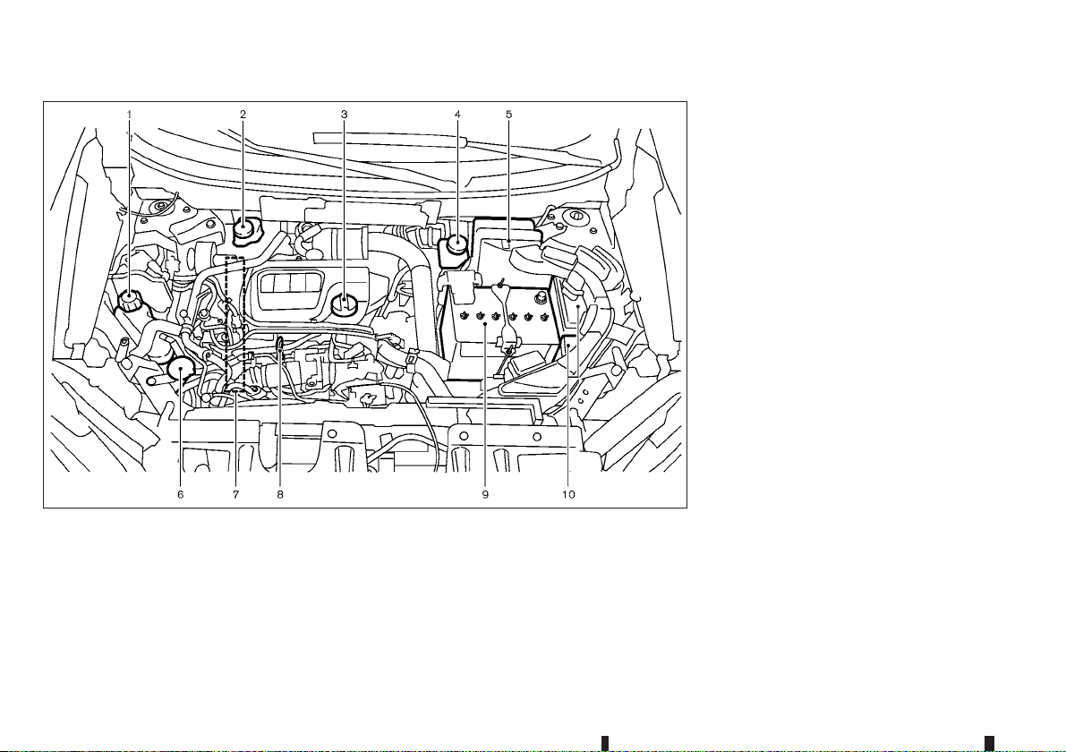
R9M ENGINE MODEL
Engine coolant reservoir (P. 8-5)
1.
Brake and clutch* fluid reservoir (P. 8-14)
2.
— RHD model
Engine oil filler cap (P. 8-7)
3.
Brake and clutch* fluid reservoir (P. 8-14)
4.
— LHD model
Air cleaner (P. 8-16)
5.
Window washer fluid reservoir (P. 8-17)
6.
Engine drive belts (P. 8-11)
7.
Engine oil dipstick (P. 8-7)
8.
Battery (P. 8-18)
9.
Fuse/fusible link box (P. 8-21)
10.
JVC0640X
For Manual Transmission (MT) Model
*:
0-16 Illustrated table of contents
Page 23

1 Safety — seats, seat belts and supplemental
Safety — seats, seat belts and supplemental
restraint system
restraint system
Seats....................................................................... 1-2
Front seats ......................................................... 1-2
Second row seats............................................... 1-5
Third row seats (where fitted) ............................. 1-7
Armrest .............................................................. 1-7
Head restraints ........................................................ 1-8
Adjustable head restraint .................................... 1-8
Non-adjustable head restraint.............................. 1-8
Remove.............................................................. 1-8
Install.................................................................. 1-9
Adjust................................................................. 1-9
Seat belts ................................................................ 1-10
Precautions on seat belt usage ........................... 1-10
Child safety ........................................................ 1-12
Pregnant women ................................................ 1-13
Injured persons................................................... 1-13
Centre mark on seat belts................................... 1-13
Three-point type seat belts.................................. 1-14
Seat belt maintenance ........................................ 1-15
Child restraints ........................................................ 1-15
Precautions on child restraint usage.................... 1-15
Universal child restraints for front seat and rear
seats (except for Ukraine and Kazakhstan) .......... 1-16
ISOFIX child restraint system (for second row
seats) ................................................................. 1-22
Child restraint anchorage (for second row
seats) ................................................................. 1-23
Child restraint installation using ISOFIX .............. 1-24
Child restraint installation using 3-point type
seat belt ............................................................. 1-26
Supplemental Restraint System (SRS) ..................... 1-30
Precautions on Supplemental Restraint
System (SRS)..................................................... 1-30
Supplemental air bag systems ............................ 1-36
Pre-tensioner seat belt system ............................ 1-38
Repair and replacement procedure ..................... 1-39
Page 24
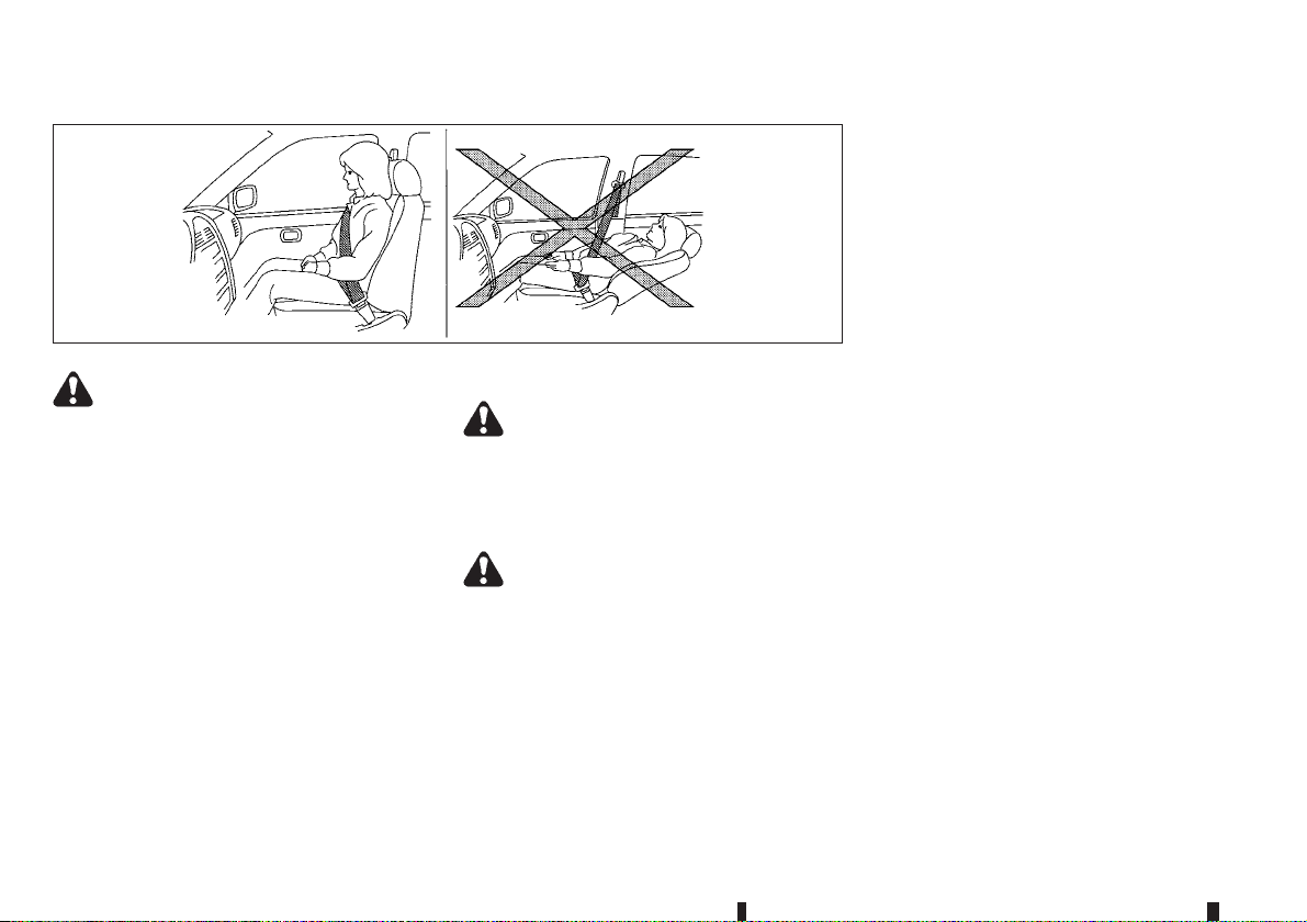
SEATS
SSS0133AZ
WARNING
Do not drive and/or ride in the vehicle with
•
the seatback reclined. This can be dangerous. The shoulder belt will not be properly
against the body. In an accident, you and your
passengers could be thrown into the shoulder belt and receive neck or other serious
injuries. You and your passengers could also
slide under the lap belt and receive serious
injuries.
For the most effective protection while the
•
vehicle is in motion, the seatback should be
upright. Always sit well back in the seat and
adjust theseat beltproperly. (See“Seat belts”
later in this section.)
CAUTION
When adjusting the seat positions, be sure not to
contact any moving parts to avoid possible injuries and/or damages.
FRONT SEATS
WARNING
Do not adjust the driver’s seat while driving so
that full attention may be given to vehicle operation.
Manual seat adjustment
WARNING
After adjusting a seat, gently shake the seat to
confirm that the seat is locked securely. If the
seat is not locked securely, it may move suddenly and could cause the loss of control of the
vehicle.
1-2 Safety — seats, seat belts and supplemental restraint system
Page 25
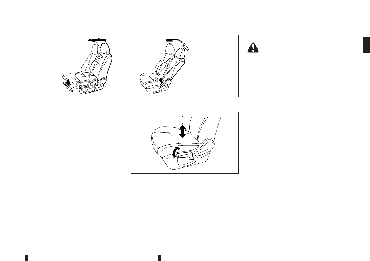
Forward and backward:
1. Pull up the adjusting lever j1.
2. Slide the seat to the desired position.
3. Release the adjusting lever to lock the seat in
position.
Reclining:
1. Pull up the adjusting lever
2. Tilt the seatback to the desired position.
3. Release the adjusting lever to lock the seatback
in position.
The reclining feature allows the adjustment of the
seatback for occupants of different sizes to help
obtain the proper seat beltfit. (See “Seat belts” later
in this section.)
The seatback may be reclined to allow occupants to
rest when the vehicle is parked.
j2.
JVR0332XZ
Seat lifter (where fitted):
JVR0333XZ
Pull up or push down the adjusting lever to adjust
the seat height until thedesired position is achieved.
Power seat adjustment
WARNING
Never leave children or adults who would normally require the support of others alone in the
vehicle. Pets should not be left alone either. They
could unknowingly activate switches or controls
and inadvertently become involved in a serious
accident and injure themselves.
Operating tips:
The power seat motor has an auto-reset over-
•
load protection circuit. If the motor stops during
the seat adjustment, wait 30 seconds, then reactivate the switch.
To avoid discharge of the battery, do not operate
•
the power seats for a long period of time when
the engine is not running.
Safety — seats, seat belts and supplemental restraint system 1-3
Page 26
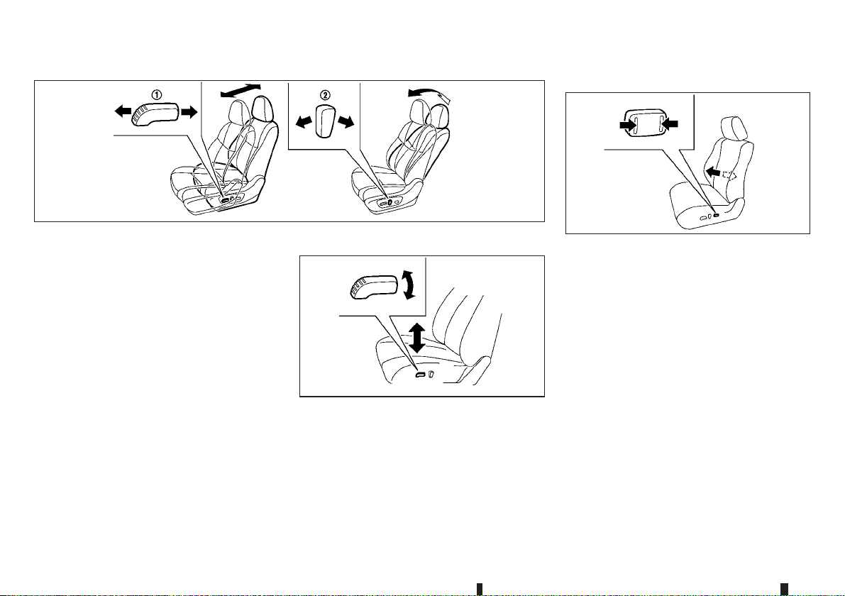
Lumbar support (where fitted):
Forward and backward:
Seat lifter (where fitted):
Move forward or backward the adjusting switch j1
to the desired position.
Reclining:
Move forward or backward the adjusting switch
j2
to the desired position.
The reclining feature allows the adjustment of the
seatback for occupants of different sizes to help
obtain the proper seat beltfit. (See “Seat belts” later
in this section.)
The seatback may be reclined to allow occupants to
rest when the vehicle is parked.
Pull up or push down the adjusting switch to adjust
the seat height until thedesired position is achieved.
1-4 Safety — seats, seat belts and supplemental restraint system
JVR0334XZ
SSS1053Z
The lumbar support feature provides lower back
support to the driver.
Push each side of the adjusting switch to adjust the
seat lumbar area until the desired position is
achieved.
JVR0119XZ
Page 27
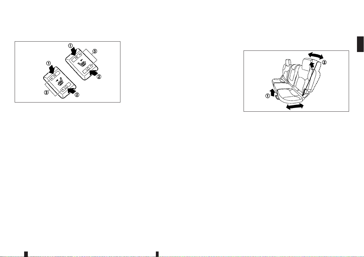
Heated seats (where fitted)
JVR0322XZ
The front seats can be warmed by built-in heaters.
The switches located on the centre console can be
operated independently of each other.
1. Start the engine.
2. Select heat range.
For high heat, push the HI (High) side of the
•
switch
j1.
For low heat, push the LO (Low) side of the
•
switch
j2.
The indicator light j3 will illuminate when low
•
or high is selected.
3. To turn off the heater, return the switch to the
level position. Make sure the indicator light turns
off.
The heater is controlled by a thermostat, automatically turning the heater on and off. The indicator light will remain on as long as the switch is
on.
When the vehicle’s interior is warmed, or before
you leave the vehicle, be sure to turn off the
switch.
CAUTION
The battery could run down if the seat heater
•
is operated while the engine is not running.
Do not use the seat heater for extended peri-
•
ods or when no one is using the seat.
Do not put anything on the seat which insu-
•
lates heat, such as a blanket, cushion, seat
cover, etc. Otherwise, the seat may become
overheated.
Do not place anything hard or heavy on the
•
seat or pierce it with a pin or similar object.
This may result in damage to the seat heater.
Any liquid spilled on the heated seat should
•
be removed immediately with a dry cloth.
When cleaning the seat, never use petrol, thin-
•
ner, or any similar materials.
SECOND ROW SEATS
Adjustment
JVR0330XZ
Forward and backward (where fitted):
1. Pull up the adjusting lever
2. Slide the seat to the desired position.
3. Release the adjusting lever
position.
Reclining (where fitted):
1. Pull the adjusting lever
2. Tilt the seatback to the desired position.
3. Release the adjusting lever
back in position.
The reclining feature allows the adjustment of the
seatback for occupants of different sizes to help
obtain the proper seat beltfit. (See “Seat belts” later
in this section.)
j1.
j1 to lock the seat in
j2.
j2 to lock the seat-
Safety — seats, seat belts and supplemental restraint system 1-5
Page 28
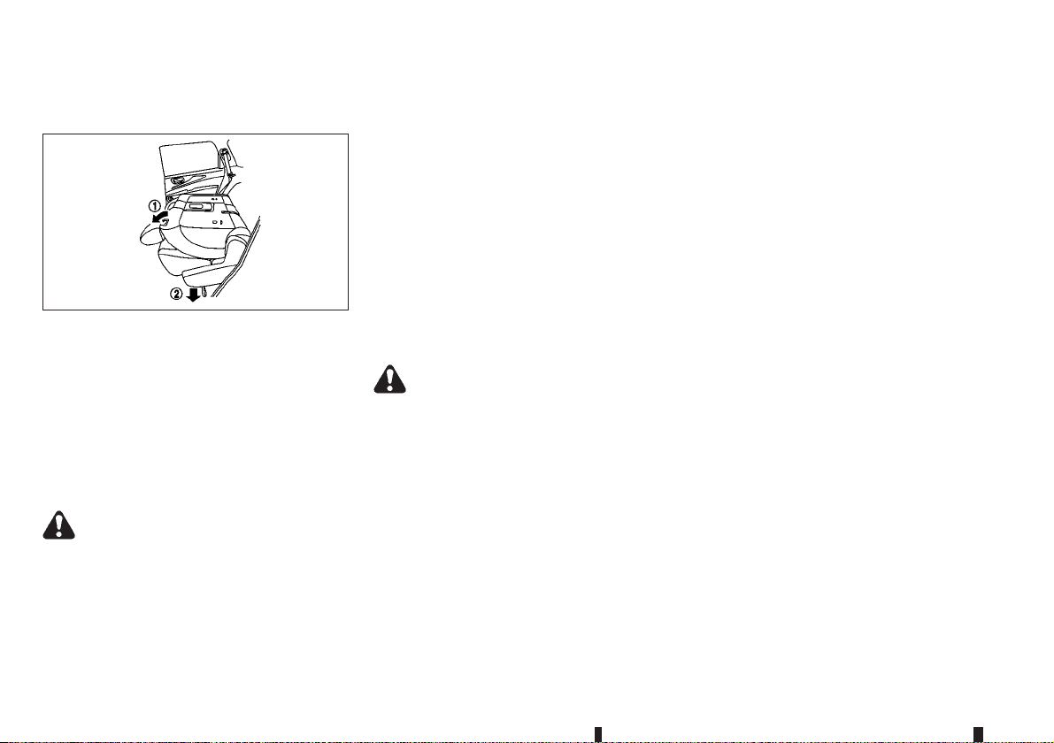
The seatback may be reclined to allow occupants to
rest when the vehicle is parked.
JVR0449XZ
Folding:
1. For vehicles not equipped with third row seat:
Pull up the lever
For vehicles equipped with third row seat: Pull
up the lever
lower side of the outboard seats to fold the
seatback flat.
2. To return the seats to a seating position, push up
on the seatback until it latches in place.
WARNING
Never allowanyone toride in the luggage area
•
or on the rear seats when they are in the folddown position. Use of these areas by passengers without proper restraints could result in
serious injury or death in an accident or sudden stop.
j1 and fold the seatback flat.
j1 and pull the strap j2 on the
Do not fold down the second row seats when
•
occupants are in the second row seat area or
any luggage is on the second row seats.
Properly secure all luggage to help prevent it
•
from sliding or shifting. Do not place luggage
higher than the seatbacks.
When returning the seatbacks to the upright
•
position, be certain they are completely secured in the latched position. If they are not
completely secured, passengers may be injured in an accident or sudden stop.
Walk-in mechanism (Three-row model):
The second row seats can tilt and slide for easy
entry/exit to/from the third row seats.
WARNING
After operating the walk-in mechanism, be sure
to return the seat to the rearmost position and
then tilt up the seatback until it latches.
CAUTION
When operating the walk-in mechanism, push
•
and hold the seatback and operate slowly. If
the seatback is tilted down quickly and then
allowed to slide, there is a risk that it could
contact your face or other parts of your body,
or pinch your hand or foot, causing injury.
When operating the walk-in mechanism, be
•
sure not to contact any moving parts to avoid
possible injuries and/or damage.
When operating the walk-in mechanism, be
•
sure that the second row seats are not occupied by passengers and/or any objects to
avoid possible injuries and/or damage.
Do not operate the walk-in mechanism with
•
objects, drinks, etc. on the seat. This may
cause objects to break or cause the passenger room to be soiled.
1-6 Safety — seats, seat belts and supplemental restraint system
Page 29
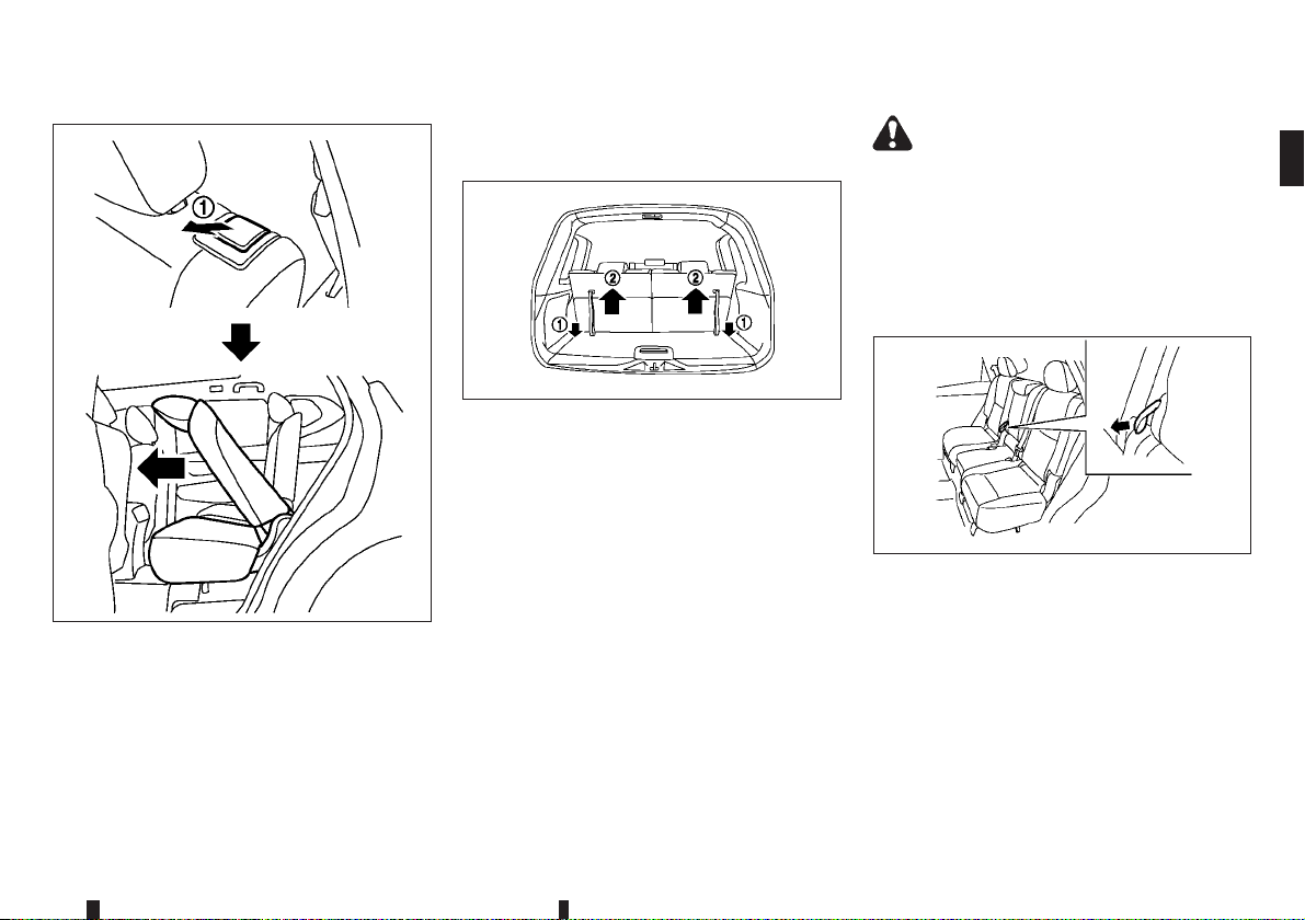
JVR0355X
1. Pull the lever j1 to tilt down the seatback.
2. Slide the seat forward.
3. When returning the seat to its original position,
slide the seat backward, tilt the seatback up and
then secure it in place.
THIRD ROW SEATS (where fitted)
Folding
JVR0329XZ
To fold the third row seats flat for maximum cargo
capacity:
1. Make sure the head restraints are all the way
down.
2. Pull the strap
3. Once released, push the seatback forward
To return the third row seats to a seating position:
Use the pull straps
back until the seatback latches into position. Make
sure to properly raise each seatback to an upright
and secured position.
j1 to release the seat.
j2.
j1 to raise each seatback. Pull
WARNING
When the seat is returned to the normal seating
position, the head restraints must be returned to
the upright position to properly protect vehicle
occupants.
ARMREST
Pull the armrest down until it rests on the seat cushion.
JVR0337XZ
Second row seats
Fold down thearmrest whilepulling thestrap (where
fitted) until it rests on the seat cushion.
Safety — seats, seat belts and supplemental restraint system 1-7
Page 30
HEAD RESTRAINTS
WARNING
Head restraints supplement the other vehicle
safety systems. They may provide additional protection against injury in certain rear end collisions. Adjustable head restraints must be adjusted properly, as specified in this section.
Check the adjustment after someone else uses
the seat. Do not attach anything to the head restraint stalks or remove the head restraint. Do
not use the seat if the head restraint has been
removed. If the head restraint was removed, reinstall and properly adjust the head restraint before an occupant uses the seating position. Failure to follow these instructions can reduce the
effectiveness of the head restraint. This may increase the risk of serious injury or death in a collision.
Your vehicle is equipped with a head restraint
•
that may be integrated, adjustable or non-adjustable.
Adjustable head restraints have multiple notches
•
along the stalk to lock them in a desired adjustment position.
The non-adjustable head restraints have single
•
locking notch to secure them to the seat frame.
Proper Adjustment:
•
– For the adjustable type, align the head re-
straint so the centre of your ear is approximately level with the centre of the head restraint.
– If your ear position is still higher than the rec-
ommended alignment, place the head
restraint at the highest position.
If the head restraint has been removed, ensure
•
that it is reinstalled and locked in place before
riding in that designated seating position.
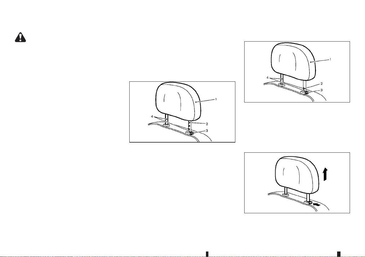
ADJUSTABLE HEAD RESTRAINT
1. Removable head restraint
2. Multiple notches
3. Lock knob
4. Stalks
SSS0992Z
NON-ADJUSTABLE HEAD RESTRAINT
JVR0203XZ
1. Removable head restraint
2. Single notch
3. Lock knob
4. Stalks
REMOVE
SSS1037Z
Use the following procedure to remove the head
restraint.
1-8 Safety — seats, seat belts and supplemental restraint system
Page 31
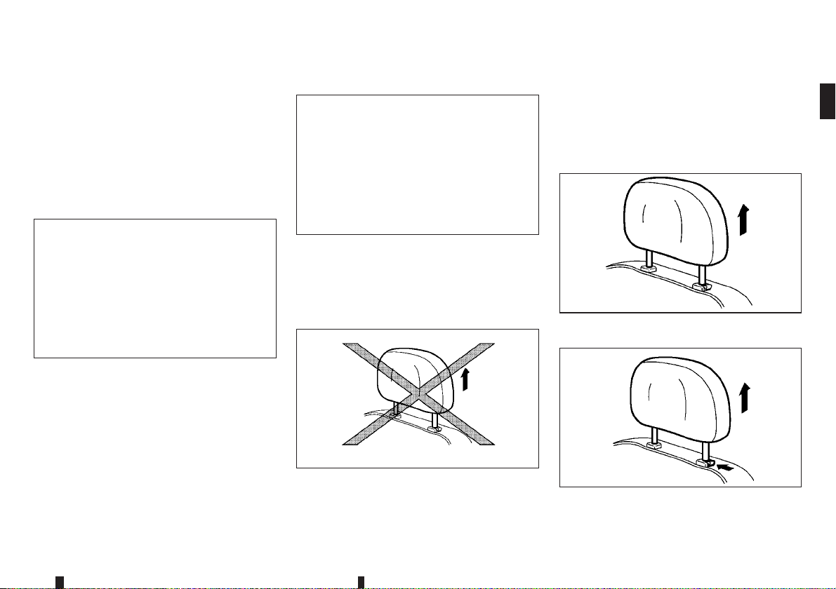
1. Pull the head restraint up to the highest position.
2. Push and hold the lock knob.
3. Remove the head restraint from the seat.
4. Store the head restraint properly in a secure
place so it is not loose in the vehicle.
5. Reinstall and properly adjust the head restraint
before an occupant uses the seating position.
INSTALL
SSS1038Z
1. Align the head restraint stalks with the holes in
the seat. Make sure that the head restraint is facing the correct direction. The stalk with the adjustment notch
with the lock knob
2. Push and hold the lock knob and push the head
restraint down.
3. Properly adjust the head restraint before an occupant uses the seating position.
j1 must be installed in the hole
j2.
ADJUST
SSS0997Z
For adjustable head restraint
Adjust the head restraint so the centre is level with
the centre of your ears. If your ear position is still
higher than the recommended alignment, place the
head restraint at the highest position.
JVR0259XZ
For non-adjustable head restraint
Make sure the head restraint is positioned from the
stored position or any non-latch position so the lock
knob is engaged in the notch before riding in that
designated seating position.
Raise
SSS1035Z
Type A
To raise the head restraint, pull it up.
SSS1037Z
Type B
To raise the head restraint, push and hold the lock
knob. Then, pull it up.
Safety — seats, seat belts and supplemental restraint system 1-9
Page 32
SEAT BELTS
Make sure the head restraint is positioned from the
stored position or any non-latch position so the lock
knob is engaged in the notch before riding in that
designated seating position.
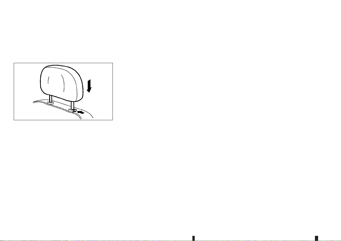
Lower
SSS1036Z
To lower, push and hold the lock knob and push the
head restraint down.
Make sure the head restraint is positioned so the
lock knob is engaged in the notch before riding in
that designated seating position.
PRECAUTIONS ON SEAT BELT
USAGE
If you are wearing the seat belt properly adjusted
and sitting upright and well back inthe seat,chances
of being injured or killed in an accident and/or the
severity of injury may be greatly reduced. NISSAN
strongly encourages you and all of your passengers
to buckle up every time you drive, even if your seating position includes the supplemental air bag systems.
1-10 Safety — seats, seat belts and supplemental restraint system
Page 33
SSS0134AZ
SSS0014Z
SSS0136AZ
SSS0016Z
Safety — seats, seat belts and supplemental restraint system 1-11
Page 34
WARNING
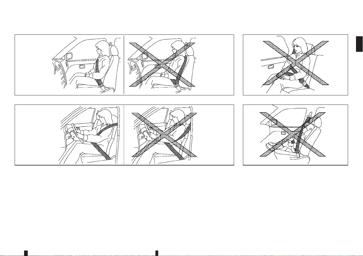
Seat beltsare designed to bear upon thebony
•
structure of the body, and should be worn low
across the front of the pelvis or the pelvis,
chest and shoulders, as applicable; wearing
the lap section of the belt across the abdominal area must be avoided. Serious injury may
occur if a seat belt is not worn properly.
Position the lap belt as low and snug as pos-
•
sible around the hips, not the waist. A lap belt
worn too high could increase the risk of internal injuries in an accident.
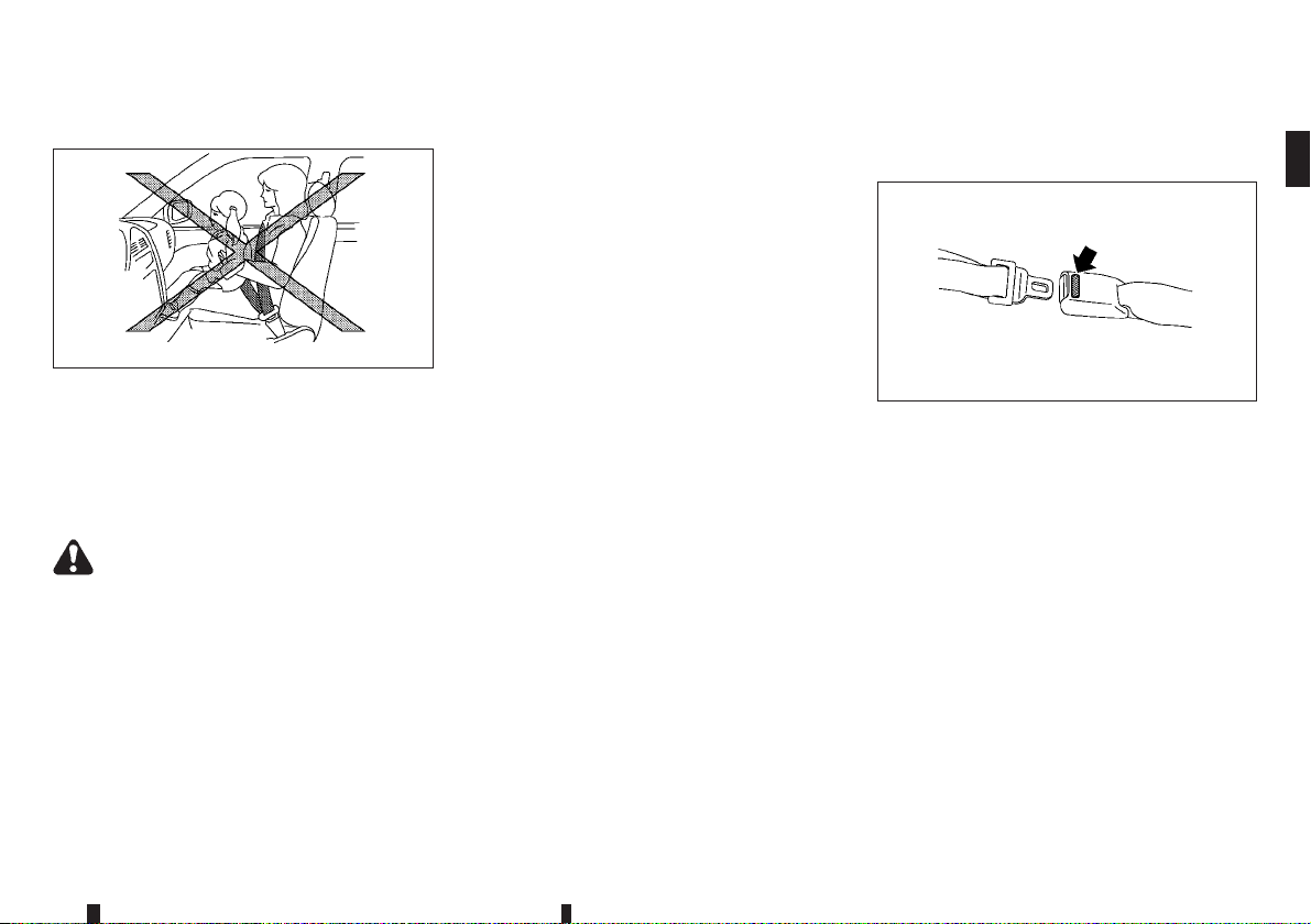
Do not allow more than one person to use the
•
same seat belt. Each belt assembly must only
be used by one occupant; it is dangerous to
put a belt around a child being carried on the
occupant’s lap.
Never carry more people in the vehicle than
•
there are seat belts.
Never wear seat belts inside out. Belts should
•
not beworn with straps twisted.Doing so may
reduce their effectiveness.
Seat belts should be adjusted as firmly as
•
possible, consistent with comfort, to provide
the protection for which they have been designed. A slack belt will greatly reduce the
protection afforded to the wearer.
Every person who drives or rides in this ve-
•
hicle should use a seat belt at all times. Chil-
dren should be properly restrained in the rear
seat and, if appropriate, in a child restraint
system.
Do not run the belt behind your back or under
•
your arm. Always route the shoulder belt over
your shoulder and across your chest. The belt
should be away from your face and neck, but
not falling off your shoulder. Serious injury
may occur if a seat belt is not worn properly.
No modificationsor additionsshould be made
•
by the user which will either prevent the seat
belt adjusting devices from operating to remove slack, or prevent the seat belt assembly
from being adjusted to remove slack.
Care should be taken to avoid contamination
•
of the webbing with polishes, oils and chemicals, and particularly battery acid. Cleaning
may safely be carried out using mild soap and
water. The belt should be replaced if webbing
becomes frayed, contaminated or damaged.
All seat belt assemblies including retractors
•
and attaching hardware should be inspected
after any collisionby aNISSAN dealeror qualified workshop. NISSAN recommends that all
seat belt assemblies in use during a collision
be replaced unless the collision was minor
and the belts show no damage and continue
to operate properly. Seat belt assemblies not
in use during a collision should also be inspected and, when necessary, replaced if either damage or improper operation is noted.
It is essential to replace the entire assembly
•
after it has been worn in a severe impact even
if damage to the assembly is not obvious.
Once the pre-tensioner seat belt has acti-
•
vated, it cannot be reused. Itmust be replaced
together with the retractor. Contact a NISSAN
dealer or qualified workshop.
Removal and installation of the pre-tensioner
•
seat belt system components should be done
by a NISSAN dealer or qualified workshop.
CHILD SAFETY
WARNING
Infants and children need special protection.
•
The vehicle’sseat belts may not fitthem properly. The shoulder belt may come too close to
the face or neck. The lap belt may not fit over
their small hipbones. In an accident, an improperly fitted seat belt could cause serious
or fatal injury.
Always use an appropriate child restraint sys-
•
tem.
Children need adults to help protect them. They
need to be properly restrained. The proper restraint
depends on the child’s size.
1-12 Safety — seats, seat belts and supplemental restraint system
Page 35
Infants and small children
SSS0099Z
NISSAN recommends that infants and small children be seated in a child restraint system. You
should choose a child restraint system that fits your
vehicle and the child, and always follow the manufacturer’s instructions for installation and use.
Large children
WARNING
Never allow children to stand or kneel on any
•
seats.
Never allow children in the cargo areas while
•
the vehicle is moving. A child could be seriously injured in an accident or sudden stop.
Children who are too large for a child restraint system should be seated and restrained by the seat
belts that are provided.
If thechild’s seating position has a shoulder belt that
fits close to the face or neck, the use of a booster
seat (commercially available) may help overcome
this. The booster seat should raise the child so that
the shoulder belt is properly positioned across the
top, middle portion of the shoulder and the lap belt
is low on the hips. The booster seat should also fit
the vehicle seat. Once the child has grown so that
the shoulder belt is no longer on or near the face or
neck of the child, use the shoulder belt without the
booster seat. In addition, there are many types of
child restraint systems available for larger children
that should be used for maximum protection.
PREGNANT WOMEN
NISSAN recommends that pregnant women use
seat belts. The seat belt should be worn snug, and
always position the lap belt as low as possible
around the hips, not the waist. Place the shoulder
belt over your shoulder andacross yourchest. Never
run the lap/shoulder belt over your abdominal area.
Contact your doctor for specific recommendations.
INJURED PERSONS
NISSAN recommends that injured persons use seat
belts. Contact your doctor for specific recommendations.
CENTRE MARK ON SEAT BELTS
Selecting correct set of seat belts
SSS0671Z
The centre seat belt buckle is identified by the CENTER mark. The centre seat belt tongue can be fastened only into the centre seat belt buckle.
Safety — seats, seat belts and supplemental restraint system 1-13
Page 36
THREE-POINT TYPE SEAT BELTS
SSS0292Z
WARNING
Every person who drives or rides in this vehicle
should use a seat belt at all times.
Fastening seat belts
WARNING
The seatback should not be in a reclined position
any morethan needed for comfort.Seat belts are
most effective when the passenger sits well back
and straight up in the seat.
1. Adjust the seat. (See “Seats” earlier in this section.)
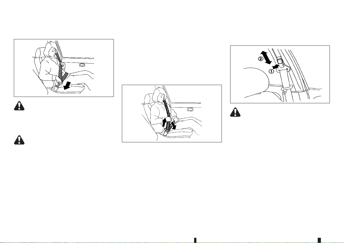
2. Slowly pull the seat belt out of the retractor and
insert the tongue into the buckle until you hear
and feel the latch engage.
The retractor is designed to lock during a
•
sudden stop or on impact. A slow pulling
motion permits the seat belt to move, and
allows you some freedom of movement in
the seat.
If the seat belt cannot be pulled from its
•
fully retracted position, firmly pull the belt
and release it. Then smoothly pull the belt
out of the retractor.
SSS0467Z
3. Position the lap belt portion low and snug on the
hips as shown.
4. Pull the shoulder belt portion toward the retractor to take up extra slack. Be sure the shoulder
belt is routed over your shoulder and is snug
across your chest.
Shoulder belt height adjustment
(where fitted)
SSS0351AZ
WARNING
The shoulder belt anchor height should be
•
adjusted to the position best for you. Failure
to do so may reduce the effectiveness of the
entire restraint system and increase the
chance or severity of injury in an accident.
The shoulder belt should rest on the middle
•
of the shoulder. It must not rest against the
neck.
Be sure that the seat belt is not twisted in any
•
way.
Be sure that the shoulder belt anchor is se-
•
cured by trying to move the shoulder belt anchor up and down after adjustment.
The shoulder belt anchor height should be adjusted
to the position best for you.
1-14 Safety — seats, seat belts and supplemental restraint system
Page 37
CHILD RESTRAINTS
The belt should be away from your face and neck,
but not falling off your shoulder.
To adjust, pull the release button
shoulder belt anchor to the proper position
that the belt passes over the centre of the shoulder.
Release the button to lock the shoulder belt anchor
into position.
j1 and move the
j2,so
Unfastening seat belts
Push the button on the buckle. The seat belt automatically retracts.
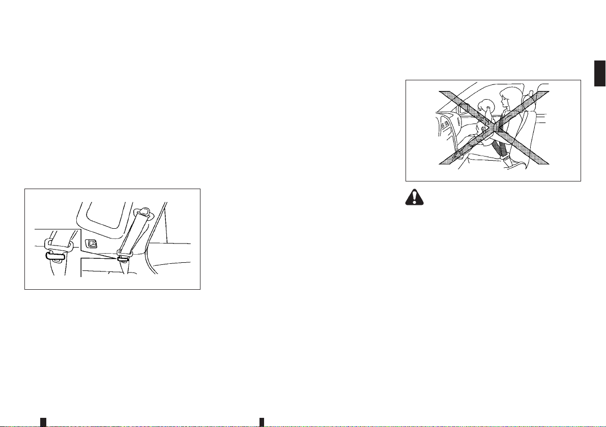
Belt hook (where fitted)
JVR0438XZ
Seat belt can be hooked on the belt hook.
Checking seat belt operation
Seat belt retractors are designed to lock seat belt
movement:
When the seat belt is pulled quickly from the
•
retractor.
When the vehicle slows down rapidly.
•
To increase your confidence in the seat belts, check
the operation by grasping the shoulder belt and pulling forward quickly. The retractor should lock and
restrict further belt movement. If the retractor does
not lockduring this check, contact aNISSAN dealer
or qualified workshop immediately.
SEAT BELT MAINTENANCE
Periodically check that the seat belt and all the metal
components, such as buckles, tongues, retractors,
flexible wires and anchors, work properly. If loose
parts, deterioration, cuts or other damage on the
seat belt webbing is found, the entire seat belt assembly should be replaced.
If dirt builds up in the shoulder belt guide of the seat
belt anchors,the seat belts may retractslowly. Wipe
the shoulder belt guide with a clean, dry cloth.
To clean the seat belt webbing, apply a mild soap
solution or any solution recommended for cleaning
upholstery or carpet. Then wipe with a cloth and
allow the seat belts to dry in the shade. Do not allow
the seat belts to retract until they are completely dry.
PRECAUTIONS ON CHILD
RESTRAINT USAGE
WARNING
Infants and small children should always be
•
placed in an appropriate child restraint while
riding in the vehicle. Failure to use a child
restraint can result in serious injury or death.
Infants and small children should never be
•
carried on your lap. It is not possible for even
the strongest adult to resist the forces of a
severe accident. The child could be crushed
between the adult and parts of the vehicle.
Also, do not put the same seat belt around
both your child and yourself.
NISSAN recommends that the child restraints
•
be installed in the rear seat. According to accident statistics, children are saferwhen properly restrainedin the rear seat than in thefront
seat.
SSS0099Z
Safety — seats, seat belts and supplemental restraint system 1-15
Page 38

Improper use or improper installation of a
•
child restraint can increase the risk or severity of injury for both the child and other occupants of the vehicle and can lead to serious
injury or death in an accident.
Follow all of the child restraint manufacturer’s
•
instructions for installation and use. When
purchasing a child restraint, be sure to select
one whichwill fit your child and vehicle. It may
not be possible to properly install some types
of child restraint in your vehicle.
The direction of the child restraint, either
•
front-facing or rear-facing, depends on the
type of the child restraint and the size of the
child. Refer to the child restraint manufacturer’s instructions for details.
Adjustable seatbacks should be positioned to
•
ensure full contact between childrestraint and
seatback.
After attaching a child restraint, test it before
•
you place the child in it. Push it from side to
side and tug it forward to make sure that it is
held securely in place. The child restraint
should not move more than 25 mm (1 in). If
the restraint is not secure, tighten the belt as
necessary, or install the restraint in another
seat and test it again.
When the child restraint is not in use, keep it
•
secured with the ISOFIX child restraint system or a seat belt to prevent it from being
thrown around in case of a sudden stop or
accident.
Never install a rear-facing child restraint on
•
the frontpassenger’s seatwhen thefront passenger’s air bag is available. Supplemental
front-impact air bags inflate with great force.
A rear-facing child restraint could be struck
by the supplemental front-impact air bags in
an accident and could seriously injure or kill
your child.
If the seat belt in the position where a child
•
restraint is installed requires a locking device
and if it is not used, injuries could result from
a child restraint tipping over during normal
vehicle braking or cornering.
CAUTION
Remember that a child restraint system left in a
closed vehicle can become very hot. Check the
seating surface and buckles before placing your
child in a child restraint.
NISSAN recommends that infants and small children be seated in a child restraint. You should
choose a child restraint that fits your vehicle and
always follow the manufacturer’s instructions for installation and use. In addition, there are many types
of child restraints available for larger children that
should be used for maximum protection.
UNIVERSAL CHILD RESTRAINTS FOR
FRONT SEAT AND REAR SEATS
(except for Ukraine and Kazakhstan)
WARNING
In vehicles equipped with a side air bag system,
do not let any infants or small children sit in the
front passenger’s seat as the air bag may cause
serious injury in case of deployment during a collision.
NOTE
Child restraints approved to ECE Regulation NO.
44.04 are clearlymarked withthe categories such
as Universal, Semi-universal or ISOFIX.
When selecting any child restraint, keep the following points in mind:
Choose a child restraint that complies with the
•
latest European safety standard, ECE Regulation NO. 44.04.
Place your child in the child restraint and check
•
the various adjustments to be sure the child restraint is compatible with your child. Always follow all of the recommended procedures.
Check the child restraint in your vehicle to be
•
sure it is compatible with vehicle’s seat belt system.
Refer to the tables later in this section for a list of
•
the recommended fitment positions and the approved child restraints for your vehicle.
1-16 Safety — seats, seat belts and supplemental restraint system
Page 39
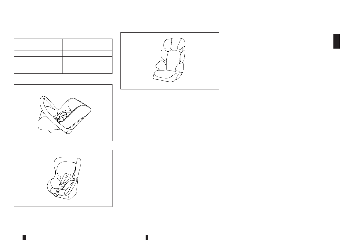
Mass group of child seat
Mass group Child’s weight
Group 0 up to 10 kg
Group 0+ up to 13 kg
Group I 9 to 18 kg
Group II 15 to 25 kg
Group III 22 to 36 kg
Examples of child seat types:
Child safety seat categories II and III
JVR0373XZ
Child safety seat categories 0 and 0+
Child safety seat categories 0+ and I
JVR0371XZ
JVR0372XZ
Safety — seats, seat belts and supplemental restraint system 1-17
Page 40
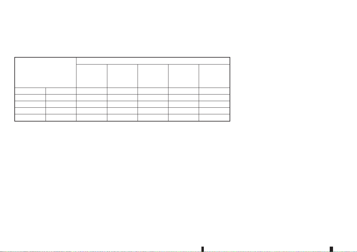
Approved child restraint positions
The following restriction is applied when using child restraints varying by infants weight and installation
position.
Suitability
Mass group
Front pas-
senger seat
(Air bag ON)
0 <10 kg X X U*2 X X
0+ <13 kg X L*2 U/L*2 X X
I 9 - 18 kg X L*2 U*2 X X
II 15 - 25 kg X L*1*2 UF/L*1*2 X X
III 22 - 36 kg X L*1*2 UF/L*1*2 X X
X: Not suitable for child restraint system.
U: Suitable for universal category child restraint system approved for this weight group.
UF: Suitable for forward-facing universal category child restraint system approved for this weight group.
L: Suitable for particular child restraints given in the following table, or vehicle list of child restraint manufacturer.
*1: If you install a child seat, remove the head restraint.
*2: If you install a child seat on sliding seat, set to most rearward slide position.
Front pas-
senger seat
(Air bag
OFF)
2nd row
outer seat
2nd row
centre seat
3rd row seat
1-18 Safety — seats, seat belts and supplemental restraint system
Page 41
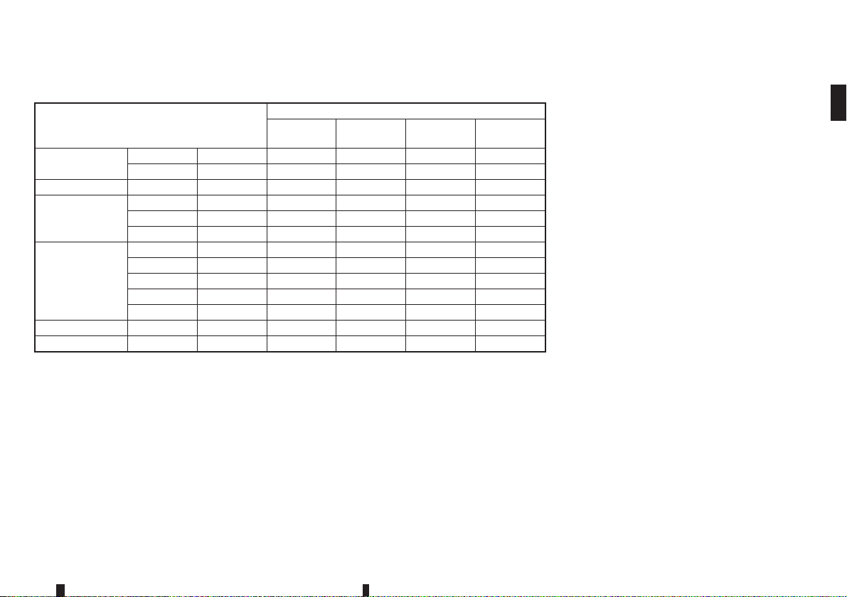
Permissible options for fitting an ISOFIX child restraint
Suitability
Mass group
Carry-cot
F ISO/L1 X X X X
G ISO/L2 X X X X
0+ (<10 kg) E ISO/R1 X IL* X X
E ISO/R1 X IL X X
0+ (<13 kg)
D ISO/R2 X IL* X X
C ISO/R3 X IL* X X
D ISO/R2 X IL* X X
C ISO/R3 X IL* X X
I(9-18kg)
B ISO/F2 X IUF X X
B1 ISO/F2X X IL*1/IUF X X
A ISO/F3 X IUF X X
II (15 - 25 kg) — — X IL*1 X X
III (22 - 36 kg) — — X IL*1 X X
X: Not suitable for child restraint system.
IUF: Suitable for universal category forward facing child restraint system approved for this weight group.
IL: Suitable particular ISOFIX category child restraint system (CRS) given in the below list or vehicle list of child seat
manufacturer.
IL*: Suitable particular ISOFIX category child restraint system (CRS) given in the vehicle list of child seat manufacturer.
*1: If you install a child seat, remove the head restraint.
Front pas-
senger seat
2nd row
outer seat
2nd row
centre seat
3rd row
seat
Safety — seats, seat belts and supplemental restraint system 1-19
Page 42
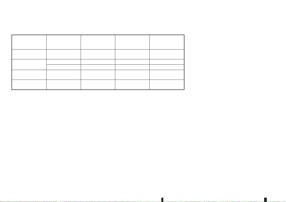
List of Universal recommended child restraints
0+ (<13 kg)
I(9-18kg)
II (15 - 25 kg)
III (22 - 36 kg)
Front passenger
seat
(Air bag OFF)
Maxi Cosi Cabrio
Fix
Römer King plus Römer King plus — —
— Römer Duo plus — —
Römer Kid fix
(belt mounted)
Römer Kid fix
(belt mounted)
2nd row outer seat
Maxi Cosi Cabrio
Fix
Römer Kid fix
(belt mounted)
Römer Kid fix
(belt mounted)
2nd row centre
seat
——
——
——
3rd row seat
1-20 Safety — seats, seat belts and supplemental restraint system
Page 43
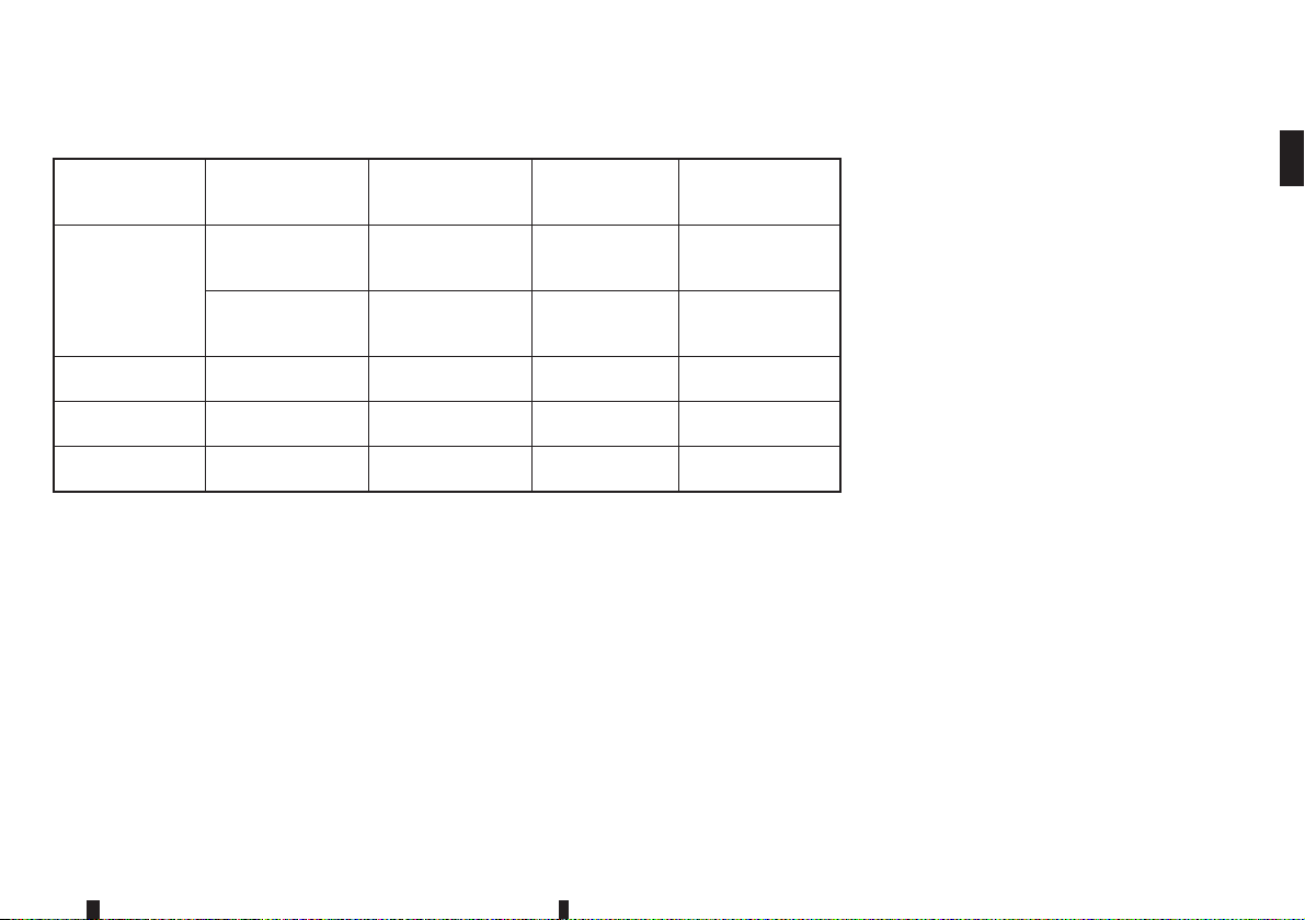
List of Semi-universal recommended child restraints
Front passenger
seat
(Air bag OFF)
Maxi Cosi Cabrio
Fix plus
0+ (<13 kg)
I(9-18kg) —
II (15 - 25 kg) —
III (22 - 36 kg) —
Easy Fix
2nd row outer seat
Maxi Cosi Cabrio
Fix plus
Easy Fix
—
Maxi Cosi Cabrio
Fix plus
Easy Fix Base
Maxi Cosi pearl
plus family fix
Römer Kid fix
(ISOFIX mounted)
Römer Kid fix
(ISOFIX mounted)
2nd row centre
seat
——
——
——
——
——
3rd row seat
Safety — seats, seat belts and supplemental restraint system 1-21
Page 44
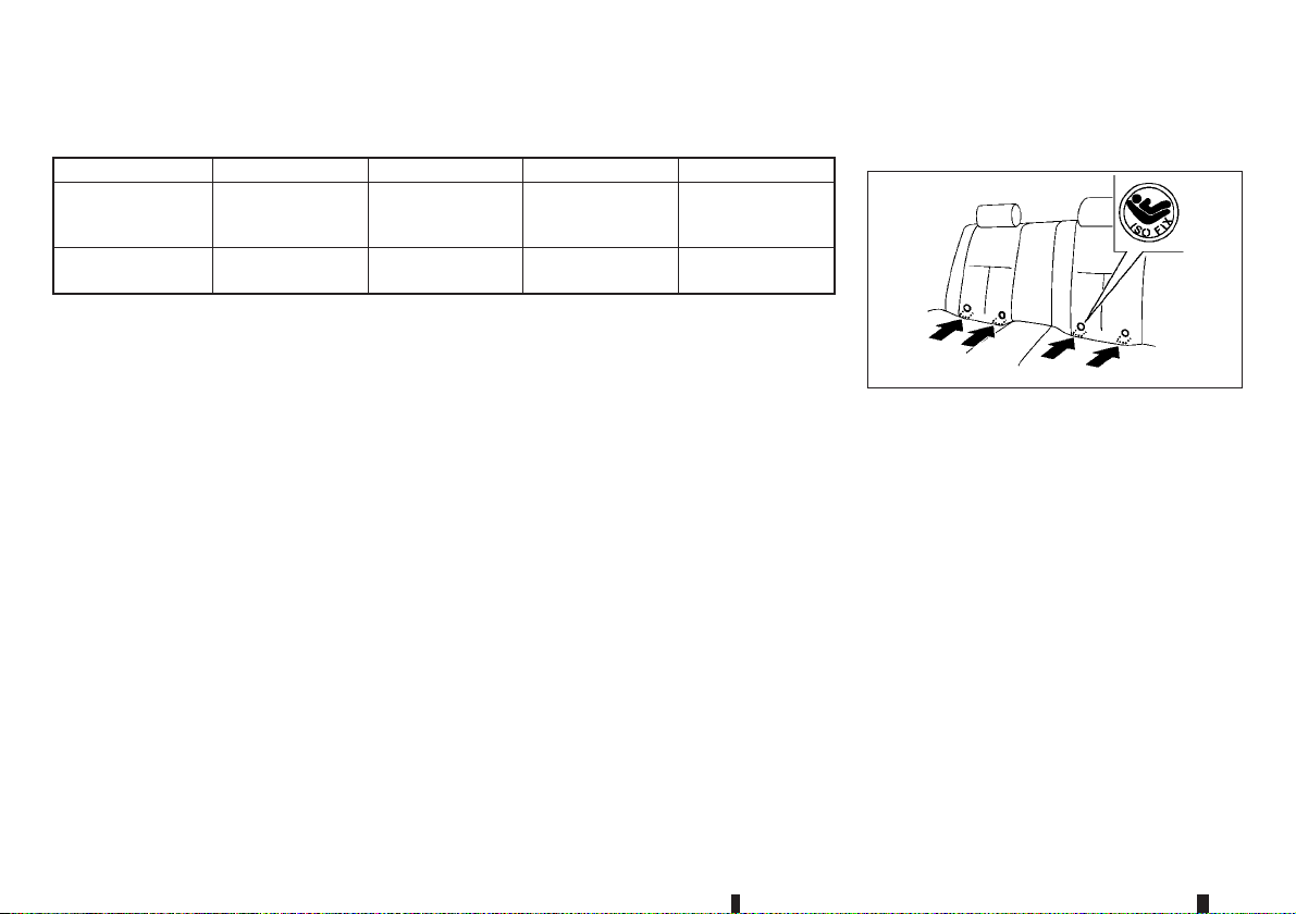
List of approved child restraints ISOFIX CHILD RESTRAINT SYSTEM
Name of CRS Fixture of CRS Facing position Category
0+ (<13 kg)
plus SHR II+
ISOFIX base
I (9 - 18 kg) Römer Duo plus *1
*1: The fitting arm of the CRS (Child Restraint System) must be engaged with the ISOFIX lower anchor with the 2nd
row seatback in the rearmost position. Then the seatback should be notched forwards to give good support (0 — 3
notches from the rearmost position) (for models with sliding seats).
Römer Baby safe
ISOFIX and sup-
port leg
ISO/F2X top
tether
Rear facing Semi-universal
Front facing Universal
(for second row seats)
JVR0351XZ
ISOFIX label location
Your vehicle is equipped with special anchor points
that are used with ISOFIX child restraint systems.
ISOFIX lower anchor point locations
The ISOFIX anchor points are provided to install
child restraints in the second row outboard seating
positions only. Do not attempt to install a child
restraint in the centre seating position using the
ISOFIX anchors.
1-22 Safety — seats, seat belts and supplemental restraint system
Page 45
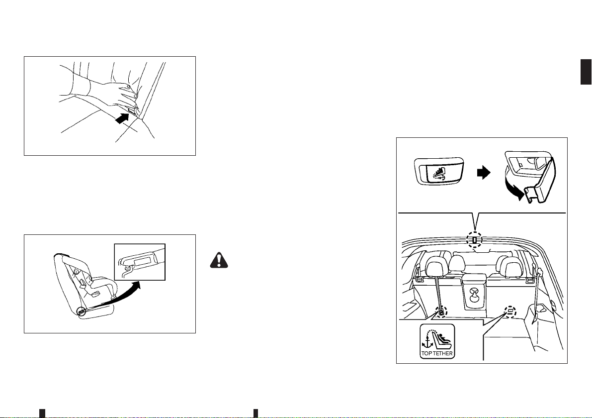
ISOFIX lower anchor location
SSS0637Z
The ISOFIX anchors are located at the rear of the
seat cushion near the seatback. A label is attached
to the seatback to help you locate the ISOFIX anchors.
ISOFIX child restraint anchor
attachments
SSS0644Z
Anchor attachment
ISOFIX child restraints include two rigid attachments that can be connected to two anchors located in the seat. With this system, you do not have
to use a vehicle seat belt to secure the child restraint. Check your child restraint for a label stating
that it is compatible with theISOFIX child restraints.
This information may also be in the instructions provided by the child restraint manufacturer.
ISOFIX child restraints generally require the use of
a top tether strap or other anti-rotation devices such
as support legs. When installing ISOFIX child restraints, carefully read and follow the instructions in
this manual and those supplied with the child restraints. (See “Child restraint installation using
ISOFIX” later in this section.)
CHILD RESTRAINT ANCHORAGE (for
second row seats)
Your vehicle is designed to accommodate a child
restraint system on the second row seat. When installing a child restraint system, carefully read and
follow the instructions in this manual and those supplied with the child restraint system.
WARNING
Child restraint anchorages are designed to
•
withstand only those loads imposed by correctly fitted child restraints. Under no circumstances are they to be used for adult seat
belts, harnesses or for attaching other items
or equipment to the vehicle. Doing so could
damage the child restraint anchorages. The
child restraint will not be properly installed
using the damaged anchorage, and a child
could be seriously injured or killed in a collision.
The child restraint top tether strap may be
•
damaged by contact with the tonneau cover
(where fitted) or items in the luggage area.
Remove the tonneau cover from the vehicle
or secure it and any luggage.Your child could
be seriously injured or killed in a collision if
the top tether strap is damaged.
Anchorage location
Type A
JVR0447X
Safety — seats, seat belts and supplemental restraint system 1-23
Page 46
Type B (example)
Anchorages are located as illustrated.
Position the top tether strap over the top of the
seatback and secure it to the tether anchorage that
provides the straightest installation. Tighten the
tether strapaccording tothe manufacturer’s instruction to remove any slack.
JVR0448XZ
CHILD RESTRAINT INSTALLATION
USING ISOFIX
WARNING
Attach ISOFIX child restraints only at the
•
specified locations. For the ISOFIX lower anchor locations, see “ISOFIX childrestraint system (forsecond row seats)” earlier inthis section. If a child restraint isnot secured properly,
your child could be seriously injured or killed
in an accident.
Do not install child restraints that require the
•
use of a top tether strap to seating positions
that do not have a top tether anchor.
Do not secure a child restraint in the centre
•
rear seating position using the ISOFIX lower
anchors. The child restraint will not be secured properly.
Inspect the lower anchors by inserting your
•
fingers into the lower anchor area and feeling
to make sure there are no obstructions over
the ISOFIX anchors, such as seat belt webbing or seat cushion material. The child restraint will not be secured properly if the
ISOFIX anchors are obstructed.
Child restraint anchorages are designed to
•
withstand only those loads imposed by correctly fitted child restraints. Under no circumstance arethey to be used for adultseat belts,
harnesses or for attaching other items or
equipment to the vehicle. Doing so could
damage the child restraint anchorages. The
child restraint will not be properly installed
using the damaged anchorage, and a child
could be seriously injured or killed in a collision.
Installation on rear outboard seats
Steps 1 and 2
Front-facing:
Be sure to follow the manufacturer’s instructions for
the proper use of your child restraint. Follow these
steps to install a front-facing child restraint on the
second row outboard seats using ISOFIX:
1. Position the child restraint on the seat
2. Secure the child restraint anchor attachments to
the ISOFIX lower anchors
3. For Europe (Mass group I-F2X, II, III):
The back of the child restraint should be secured
against the vehicle seatback. The head restraint
should be removed to obtain the correct child
restraint fit. Store the head restraint in a secure
place. Be sure to install the head restraint when
the child restraint is removed. (See “Head
restraints” earlier in this section, “Universal child
restraints for front seat and rear seats (except for
Ukraine and Kazakhstan)” earlier in this section)
j2.
SSS0646AZ
j1.
1-24 Safety — seats, seat belts and supplemental restraint system
Page 47
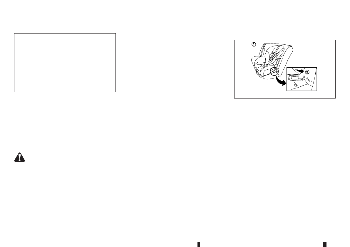
For Europe (except for Mass group I-F2X, II,
III):
For Ukraine and Kazakhstan:
The back of the child restraint should be secured
against the vehicle seat back. If necessary, adjust or remove the head restraint to obtain the
correct child restraint fit. If the head restraint is
removed, store it in a secure place. Be sure to
install the head restraint when the child restraint
is removed. If the seating position does not have
an adjustable head restraint and it is interfering
with theproper child restraint fit, tryanother seating position or a different child restraint. (See
“Head restraints” earlier in this section, “Universal child restraints for front seat and rear seats
(except for Ukraine and Kazakhstan)” earlier in
this section.)
seat cushion and seatback. Adjustable
seatbacks should be positioned to ensure full
contact between child restraint and seatback.
5. If the child restraint is equipped with a top tether
strap, route the top tether strap and secure the
tether strap to the tether anchor point. (See
“Child restraint anchorage (for second row
seats)” earlier in this section.)
6. If the child restraint is equipped with other antirotation devices such as support legs, use them
instead of the top tether strap following the child
restraint manufacturer’s instructions.
Rear-facing:
Steps 1 and 2
SSS0649AZ
Be sure to follow the manufacturer’s instructions for
the proper use of your child restraint. Follow these
steps to install a rear-facing child restraint on the
second row outboard seats using ISOFIX:
1. Position the child restraint on the seat
j1.
2. Secure the child restraint anchor attachments to
the ISOFIX lower anchors
j2.
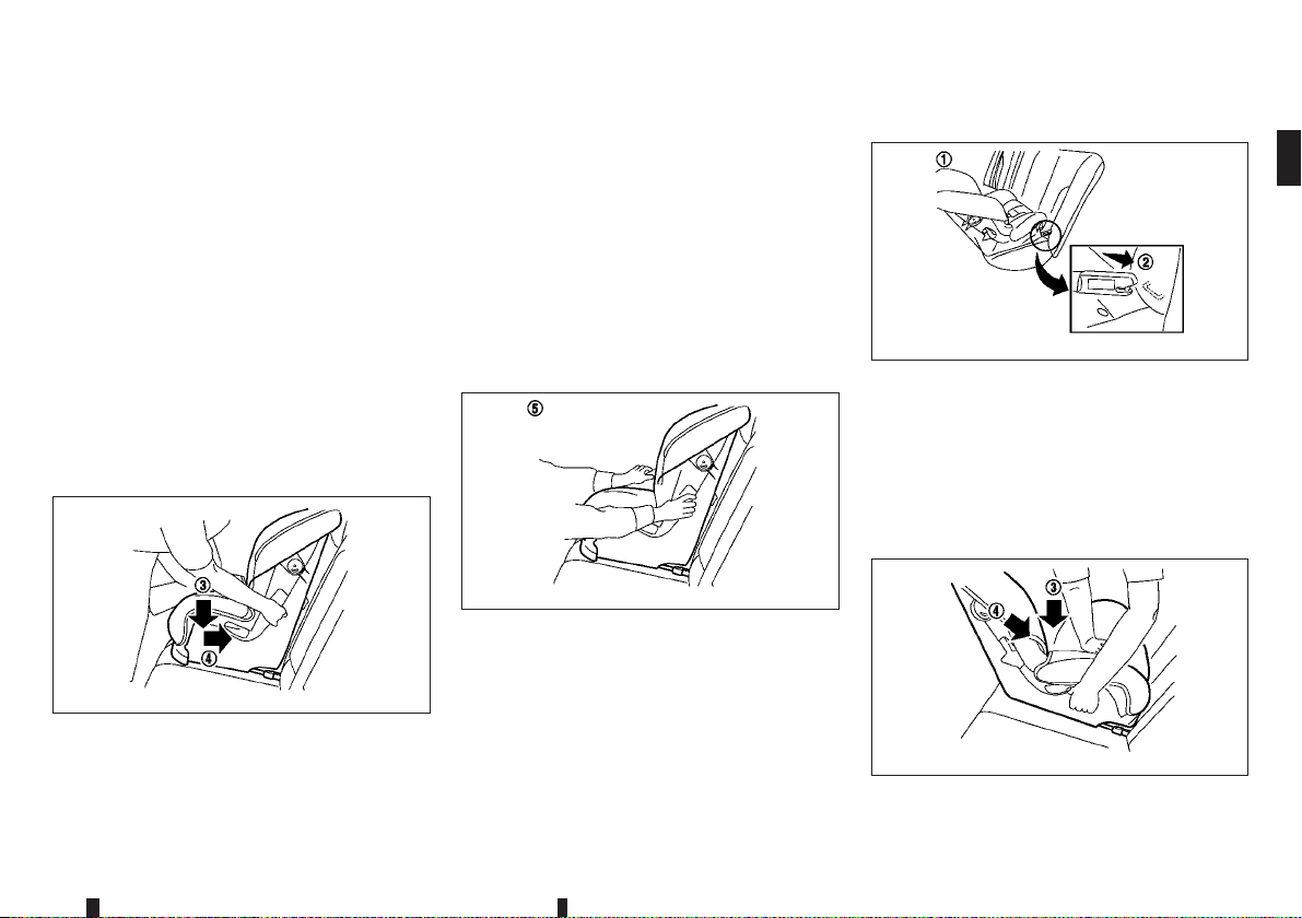
Step 4
SSS0754AZ
4. Shorten the rigid attachment to have the child
restraint firmly tightened; press downward
and rearward
j4 firmly in the centre of the child
j3
restraint with your knee to compress the vehicle
Step 7
SSS0755AZ
7. Test the child restraint before you place the child
in it
j5 . Push the child restraint from side to side
and tug it forward to make sure that it is held
securely in place.
8. Check to make sure that the child restraint is
properly secured prior to each use. If the child
restraint is loose, repeat steps 3 through 7.
Safety — seats, seat belts and supplemental restraint system 1-25
Step 3
SSS0756AZ
Page 48
3. Shorten the rigid attachment to have the child
restraint firmly tightened; press downward
and rearward
restraint with your hand to compress the vehicle
seat cushion and seatback.
4. If the child restraint is equipped with a top tether
strap, route the top tether strap and secure the
tether strap to the tether anchor point. (See
“Child restraint anchorage (for second row
seats)” earlier in this section.)
5. If the child restraint is equipped with other antirotation devices such as support legs, use them
instead of the top tether strap following the child
restraint manufacturer’s instructions.
j4 firmly in the centre of the child
j3
CHILD RESTRAINT INSTALLATION
USING 3-POINT TYPE SEAT BELT
Installation on rear seats - without
automatic locking mode
Front-facing:
Installation onrear outboard seats (for Europe
(except for Mass group II and III)):
Installation on rear outboard seats (for
Ukraine and Kazakhstan):
Adjust the head restraint to its highest position.
(See “Head restraints” earlier in this section,
“Universal child restraints for front seat and rear
seats (except for Ukraine and Kazakhstan)” earlier in this section.)
Be sure to follow the manufacturer’s instructions for
the proper use of your child restraint. Follow these
steps to install a front-facing child restraint on the
rear seats using 3-point type seat belt without automatic locking mode:
Step 6
6. Test the child restraint before you place the child
in it
j5 . Push the child restraint from side to side
and tug it forward to make sure that it is held
securely in place.
7. Check to make sure that the child restraint is
properly secured prior to each use. If the child
restraint is loose, repeat steps 3 through 6.
SSS0757AZ
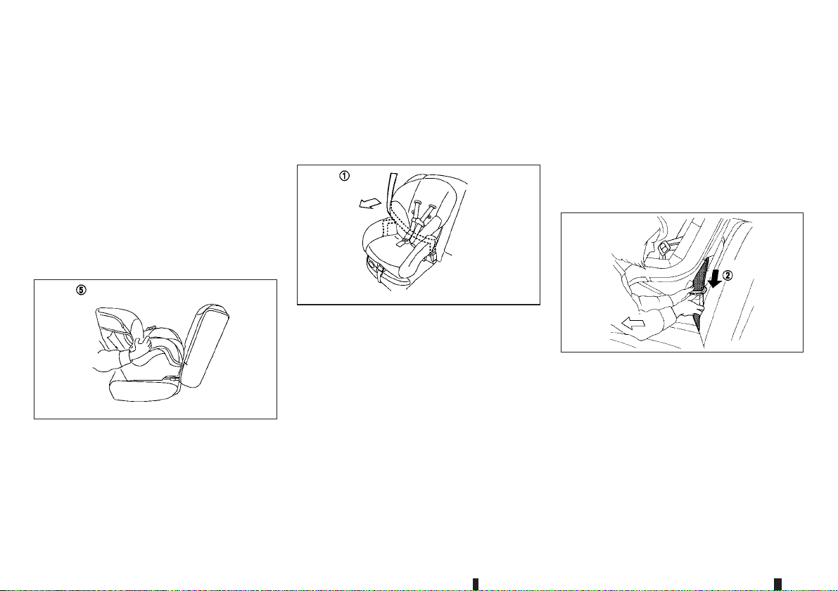
1. Position the child restraint on the seat
2. Installation on rearoutboard seats (for Europe
(Mass group II and III)):
Remove the head restraint. (See “Head
restraints” earlier in this section, “Universal child
restraints for front seat and rear seats (except for
Ukraine and Kazakhstan)” earlier in this section.)
1-26 Safety — seats, seat belts and supplemental restraint system
Step 1
SSS0758AZ
j1.
Step 3
3. Route the seat belt tongue through the child restraint and insert it into the buckle
hear and feel the latch engage.
4. To prevent slack in the seat belt webbing, it is
necessary to secure the seat belt in place with
locking devices attached to the child restraint.
SSS0493AZ
j2 until you
Page 49
6. Test the child restraint before you place the child
in it
j5 . Push the child restraint from side to side
and tug it forward to make sure that it is held
securely in place.
7. Check to make sure that the child restraint is
properly secured prior to each use. If the child
restraint is loose, repeat steps 3 through 5.
Rear-facing:
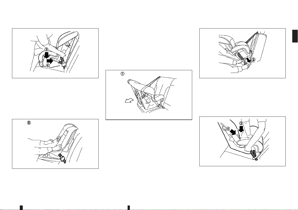
Step 5
SSS0647AZ
5. Remove any additional slack from the seat belt;
press downward
j3 and rearward j4 firmly in
the centre of the child restraint with your knee to
compress the vehicle seat cushion and seatback
while pulling up on the seat belt. Adjustable
seatbacks should be positioned to ensure full
contact between child restraint and seatback.
Step 6
SSS0638AZ
Step 1
SSS0759AZ
Be sure to follow the manufacturer’s instructions for
the proper use of your child restraint. Follow these
steps to install a rear-facing child restraint on the
rear seats using 3-point type seat belt without automatic locking mode:
1. Position the child restraint on the seat
j1.
Safety — seats, seat belts and supplemental restraint system 1-27
Step 2
SSS0654AZ
2. Route the seat belt tongue through the child restraint and insert it into the buckle
j2 until you
hear and feel the latch engage.
3. To prevent slack in the seat belt webbing, it is
necessary to secure the seat belt in place with
locking devices attached to the child restraint.
Step 4
SSS0639AZ
Page 50
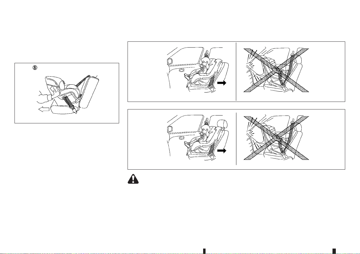
4. Remove any additional slack from the seat belt;
press downward
the centre of the child restraint with your hand to
compress the vehicle seat cushion and seatback
while pulling up on the seat belt.
j3 and rearward j4 firmly in
Installation on front passenger’s seat
Step 5
5. Test the child restraint before you place the child
in it
j5 . Push the child restraint from side to side
and tug it forward to make sure that it is held
securely in place.
6. Check to make sure that the child restraint is
properly secured prior to each use. If the child
restraint is loose, repeat steps 3 through 5.
SSS0658AZ
WARNING
Never install a rear-facing child restraint on
•
the frontpassenger’s seatwhen thefront passenger’s air bag is available. Supplemental
front-impact air bags inflate with great force.
A rear-facing child restraint could be struck
1-28 Safety — seats, seat belts and supplemental restraint system
For Europe (Mass group II and III)
For Europe (except for Mass group II and III) and for Ukraine and Kazakhstan
by the supplemental front-impact air bags in
an accident and could seriously injure or kill
your child.
Never install a child restraint with a top tether
•
strap on the front seat.
JVR0285XZ
SSS0300AZ
Page 51
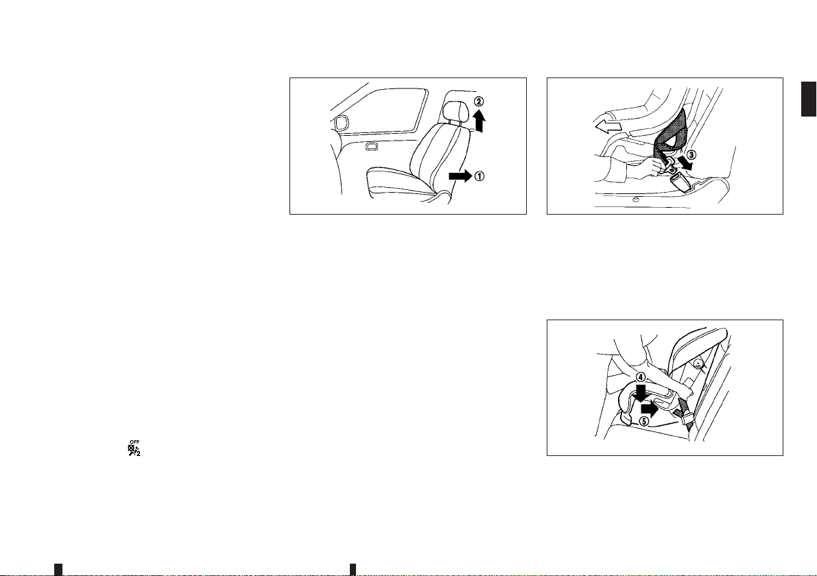
NISSAN recommends that a child restraint be
•
installed on the rear seat. However, if you
must install a child restraint on the front passenger’s seat, move the passenger’s seat to
the rearmost position.
Child restraints for infants must be used in
•
the rear-facing direction and therefore must
not be used on the front passenger’s seat
when the front passenger’s air bag is available.
Failure to use the seat belts will result in the
•
child restraint system not being properly secured. It could tip over or otherwise be unsecured and cause injury to the child in a sudden stop or collision.
Front-facing:
Be sure to follow the manufacturer’s instructions for
the proper use of your child restraint. Follow these
steps to install a front-facing child restraint on the
front passenger’s seat using 3-point type seat belt
without automatic locking mode:
1. Turn off the front passenger’s air bag using the
front passenger air bag switch. (See “Supplemental Restraint System (SRS)” later in this section.) Place the ignition switch in the “ON” position and make sure that the front passenger air
bag status light
(OFF) illuminates.
Steps 2 and 3
2. Move the seat to the rearmost position
3. For Europe (Mass group II and III):
Remove the head restraint
restraints” earlier in this section, “Universal child
restraints for front seat and rear seats (except for
Ukraine and Kazakhstan)” earlier in this section.)
For Europe (except for Mass group II and III):
For Ukraine and Kazakhstan:
Adjust the head restraint
tion. (See “Head restraints” earlier in this section, “Universal child restraints for front seat and
rear seats (except for Ukraine and Kazakhstan)”
earlier in this section.)
4. Position the child restraint in the seat.
j2 to its highest posi-
j1.
j2 . (See “Head
SSS0627Z
Step 5
5. Route the seat belt tongue through the child restraint and insert it into the buckle
hear and feel the latch engage.
6. To prevent slack in the seat belt webbing, it is
necessary to secure the seat belt in place with
locking devices attached to the child restraint.
Step 7
SSS0360CZ
j3 until you
SSS0647BZ
Safety — seats, seat belts and supplemental restraint system 1-29
Page 52
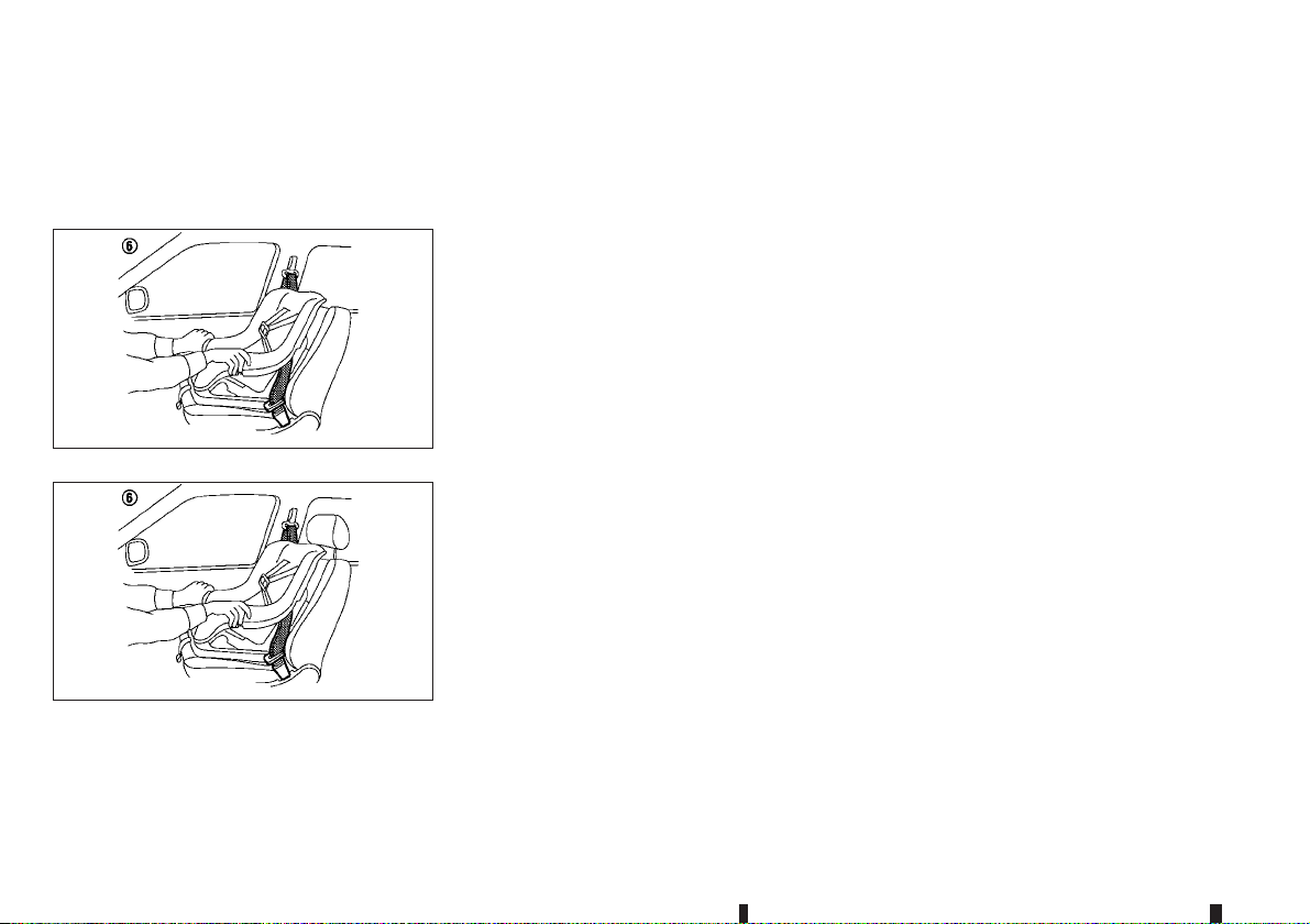
SUPPLEMENTAL RESTRAINT
SYSTEM (SRS)
7. Remove any additional slack from the seat belt;
press downward
the centre of the child restraint with your knee to
compress the vehicle seat cushion and seatback
while pulling up on the seat belt.
Step 8 (for Europe (Mass group II and III))
Step 8 (For Europe (except for Mass group II and III) and for
8. Test the child restraint before you place the child
in it
j6 . Push the child restraint from side to side
and tug it forward to make sure that it is held
securely in place.
j4 and rearward j5 firmly in
JVR0286XZ
SSS0302GZ
Ukraine and Kazakhstan
9. Check to make sure that the child restraint is
properly secured prior to each use. If the child
restraint is loose, repeat steps 6 through 8.
PRECAUTIONS ON SUPPLEMENTAL
RESTRAINT SYSTEM (SRS)
This Supplemental Restraint System (SRS) section
contains important information concerning the driver’s and passenger’s supplemental front-impact air
bags, supplemental side-impact air bags, supplemental curtain side-impact air bags and pre-tensioner seat belts.
Supplemental front-impact air bag
system
This system can help cushion the impact force to
the head and chest area of the driver and/or front
passenger in certain frontal collisions. The supplemental front-impact air bag is designed to inflate on
the front where the vehicle is impacted.
Supplemental side-impact air bag
system
This system can help cushion the impact force to
the chest area of the driver and front passenger in
certain side-impact collisions. The supplemental
side-impact air bag is designed to inflate on the side
where the vehicle is impacted.
Supplemental curtain side-impact air
bag system
This system can help cushion the impact force to
the head of the driver and passengers in front and
rear outboard seating positions in certain side-impact collisions. The supplemental curtain side-impact air bag is designed to inflate on the side where
the vehicle is impacted.
1-30 Safety — seats, seat belts and supplemental restraint system
Page 53
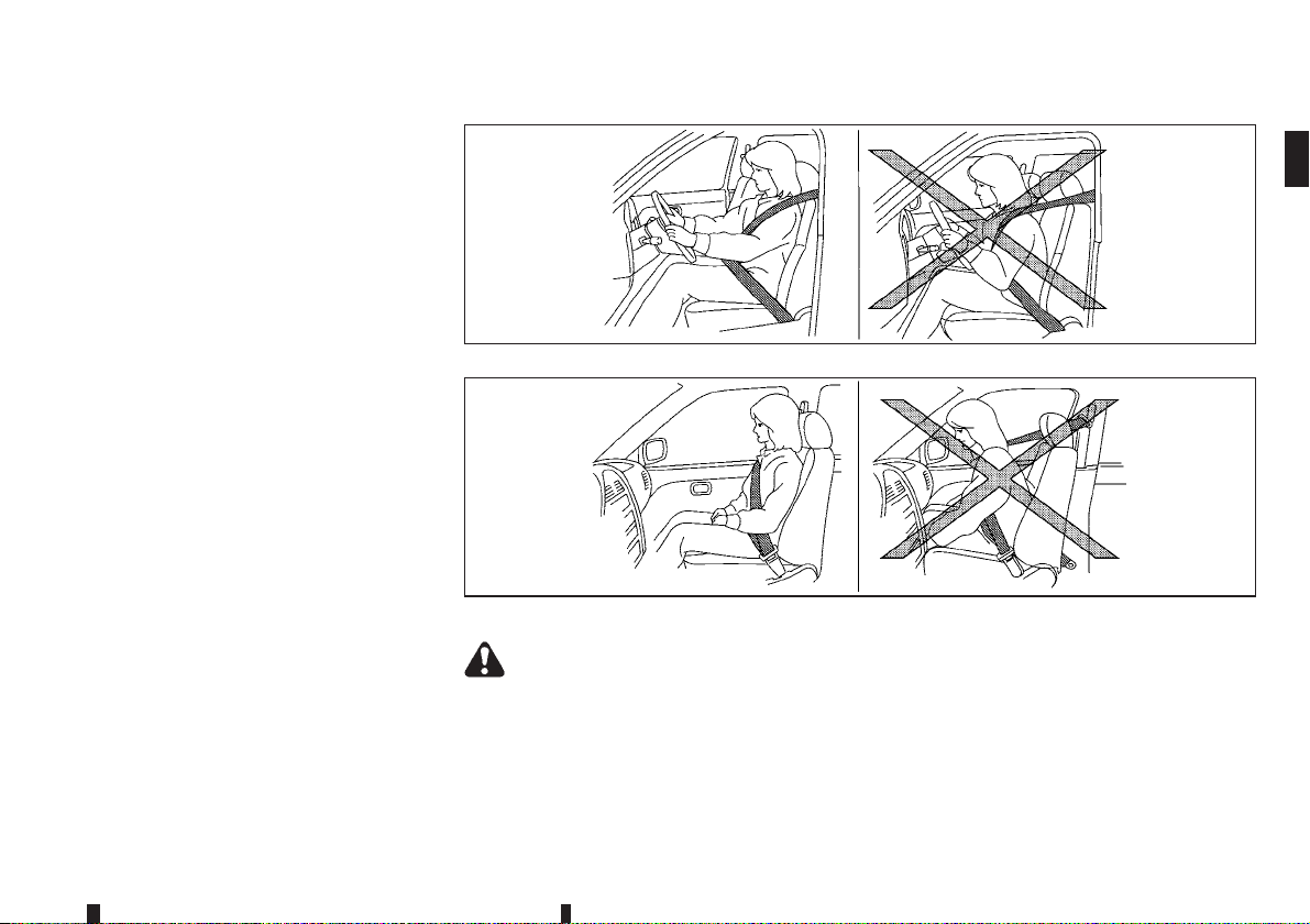
The SRS is designed to supplement the accident
protection provided by the driver’s and passenger’s
seat belts and is not designed to substitute for
them. The SRS can help save lives and reduce serious injuries. However, inflating air bags may cause
abrasions or other injuries. Air bags do not provide
protection to the lower body. Seat belts should always be correctly worn and the occupants should
always be seated a suitable distance away from the
steering wheel and instrument panel. (See “Seat
belts” earlier in this section.) The air bags inflate
quickly in order to help protect the occupants. The
force of the air bags inflating can increase the risk of
injury if the occupants are too close to, or are
against, the air bag modules during inflation. The air
bags will deflate quickly after deployment.
The SRS operates only when the ignition switch
is in the ON position.
When the ignition switch is in the ON position,
the SRS air bag warning light illuminates for
about 7 seconds and then turns off. This indicates that the SRS air bag system is operational.
(See “SRS air bag warning light” later in this section.)
WARNING
The supplemental front-impact air bags ordi-
•
narily will not inflate in the event of a side
impact, rear impact, rollover, or lower severity frontal collision. Always wear the seat belts
to help reduce the risk or severity of injury in
accidents.
SSS0131AZ
SSS0132AZ
The seat belts and the supplemental front-im-
•
pact air bags are most effective when you are
sitting well back and upright in the seat. The
front-impact air bags inflate with great force.
If you and your passengers are unrestrained,
leaning forward, sitting sideways, or out of
position in any way, you and your passengers
are at greater risk of injury or death in an accident. You and your passengers may also receive serious or fatal injuries from the supple-
Safety — seats, seat belts and supplemental restraint system 1-31
Page 54
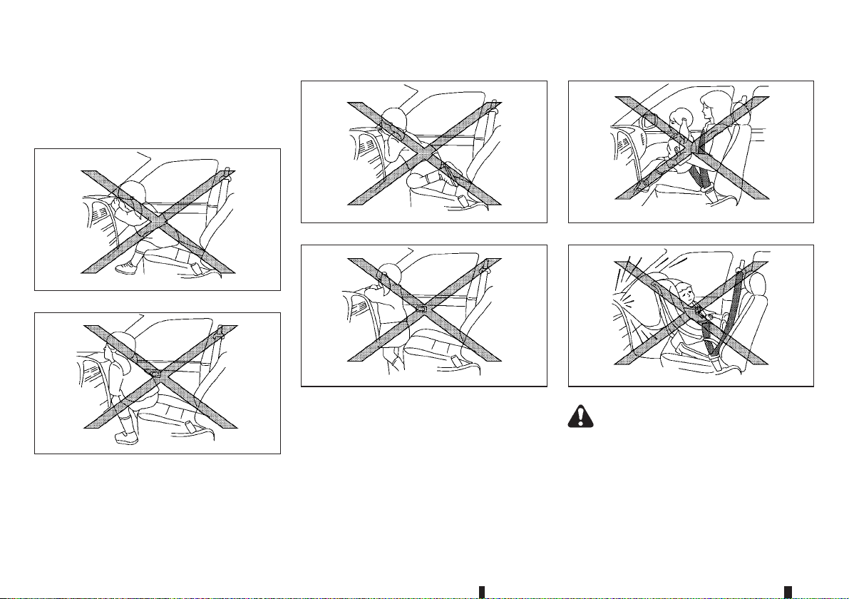
mental front-impact air bag if you are up
against it when it inflates. Always sit back
against the seatback and as far away as practical from the steering wheel or instrument
panel. Always use the seat belts.
SSS0006Z
SSS0007Z
1-32 Safety — seats, seat belts and supplemental restraint system
SSS0008Z
SSS0009Z
WARNING
Never let children ride unrestrained or extend
•
their hands or face out of the window. Do not
attempt to hold them in your lap or arms.
Some examplesof dangerousriding positions
are shown in the illustrations.
SSS0099Z
SSS0100Z
Page 55
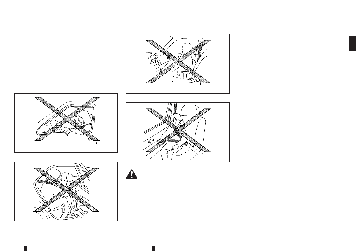
Children may be severely injured or killed
•
when the supplemental front-impact air bags,
supplemental side-impactair bags, or supplemental curtain side-impact air bags inflate if
they are not properly restrained.
Never install a rear-facing child restraint sys-
•
tem on the front seat. An inflating supplemental front-impact air bag could seriously injure
or kill your child. (See “Child restraints” earlier in this section.)
SSS0059AZ
SSS0140Z
WARNING
The supplemental side-impact air bags and
•
supplemental curtain side-impact air bags ordinarily will not inflate in the event of a front
impact, rear impact, rollover, or lower severity side collision. Always wear the seat belts
to help reduce the risk or severity of injury in
accidents.
SSS0159Z
SSS0162Z
The seat belts and the supplemental side-im-
•
pact air bags and supplemental curtain sideimpact air bags are most effective when you
are sitting well back and upright in the seat.
The supplemental side-impact air bags and
supplemental curtain side-impact air bags inflate with great force. If you and your passengers are unrestrained, leaning forward, sitting
sideways, or out of position in any way, you
and your passengers are at greater risk of
injury or death in an accident.
Do not allow anyone toplace theirhands, legs,
•
or face near the supplemental side-impact air
bags and supplemental curtain side-impact
air bags on the sides of the seatback of the
front seats or near the side roof rails. Do not
allow anyone sitting in the front seats or rear
outboard seats to extend their hands out of
the windows or lean against the doors. Some
examples of dangerous riding positions are
shown in the illustrations.
When sitting in the rear seats, do not hold
•
onto the seatback of the front seats. If the
supplemental side-impact air bags and
supplemental curtain side-impact air bags inflate, you may be seriously injured. Be especially carefulwith children,who should always
be properly restrained.
Do not use seat covers on the front seatbacks.
•
They may interfere with the supplemental
side-impact air bag inflations.
Safety — seats, seat belts and supplemental restraint system 1-33
Page 56
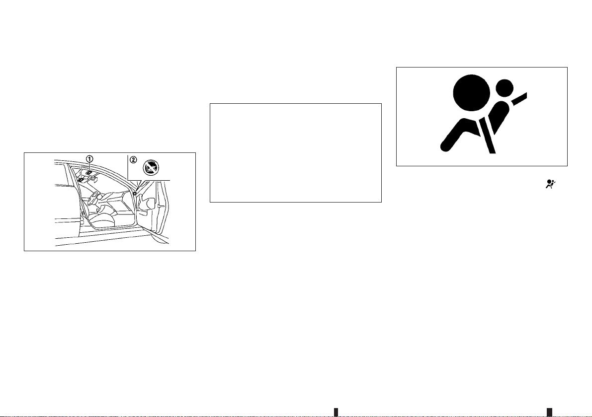
Pre-tensioner seat belt system
The pre-tensioner seat belt system activates in conjunction with the supplemental front-impact air bag.
Working with the seat belt retractor and anchor, it
helps tighten the seat belt the instant the vehicle
becomes involvedin certaintypes of collisions, helping to restrain front seat occupants. (See “Pretensioner seat belt system” later in this section.)
Air bag warning labels
SSS1023Z
Warning labels about the supplemental air bag system are placed in the vehicle as shown in the illustration.
The warning label
the driver’s and/or passenger’s sun visor.
The warning label
side of the passenger’s side body panel.
j1 is located on the surface of
j2 (where fitted) is located on the
The label(s) warn you not to fit a rear-facing child
restraint systemon the front passenger seatas such
a restraint system used in this position could cause
serious injury to the infant in case of air bag deployment during a collision.
Air bag warning label
The label
“NEVER use a rearward facing child restraint on a
seat protected by an ACTIVE AIR BAG in front of it,
DEATH or SERIOUS INJURY to the CHILD can
occur.”
In vehicles equipped with a front-impact passenger
air bag system, use a rear-facing child restraint system only on the rear seats.
When installing a child restraint system in your vehicle, always follow the child restraint system manufacturer’s instructions for installation. For additional
information, see “Child restraints” earlier in this section.
j1 warns:
JVR0243XZ
SRS air bag warning light
SPA1097Z
The SRS air bag warning light, displaying in
the meter, monitors the circuits for the air bag systems, pre-tensioner seat belt systems and all related
wiring.
When the ignition switch is in the ON position, the
SRS air bag warning light illuminates for about 7
seconds and then turns off. This indicates that the
SRS air bag systems are operational.
If any of the following conditions occur, the air bag
and/or pre-tensioner seat belt systems need servicing:
The SRS air bag warning light remains on after
•
approximately 7 seconds.
The SRS air bag warning light flashes intermit-
•
tently.
The SRS air bag warning light does not illumi-
•
nate at all.
1-34 Safety — seats, seat belts and supplemental restraint system
Page 57

Under these conditions, the air bag and/or pretensioner seat belt systems may not operate properly. They must be checked andrepaired. Contact a
NISSAN dealer or qualified workshop immediately.
Safety — seats, seat belts and supplemental restraint system 1-35
Page 58
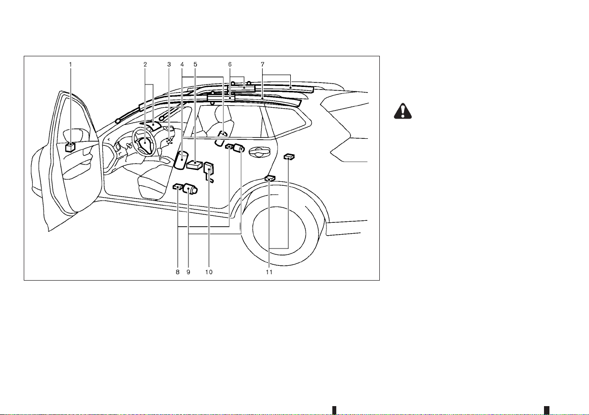
SUPPLEMENTAL AIR BAG SYSTEMS
Crash zone sensor
1.
Supplemental front-impact air bag modules
2.
Front passenger air bag switch (where fitted)
3.
Supplemental side-impact air bag modules
4.
(where fitted)
Supplemental air bag diagnosis sensor unit
5.
Supplemental curtain side-impact air bag infla-
6.
tors (where fitted)
Supplemental curtain side-impact air bag
7.
modules (where fitted)
Satellite sensors (where fitted)
8.
JVR0460X
Pre-tensioner seat belt retractors (where fit-
9.
ted)
Lap outer pre-tensioner (where fitted)
10.
Satellite sensors (where fitted)
11.
WARNING
Do not placeany objectson the steeringwheel
•
pad, on the instrument panel, and near the
front door finishers and the front seats. Do
not place any objects between any occupants
and the steering wheel pad, on the instrument panel, and near the front door finishers
and the front seats. Suchobjects maybecome
dangerous projectiles and cause injury if a
supplemental air bag inflates.
Immediately after inflation, several supple-
•
mental air bagsystem componentswill be hot.
Do not touch them: you may severely burn
yourself.
No unauthorised changes should be made to
•
any components or wiring of the supplemental air bag systems. This is to prevent accidental inflation of the supplemental air bags
or damage to the supplemental air bag systems.
Do not make unauthorised changes to your
•
vehicle’s electrical system, suspension system, frontend structure, and side panels. This
could affect proper operation of the supplemental air bag systems.
1-36 Safety — seats, seat belts and supplemental restraint system
Page 59
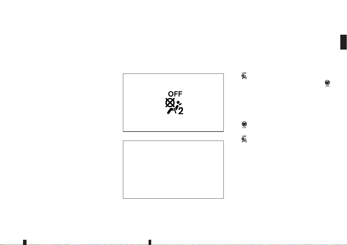
Tampering with the supplemental air bag sys-
•
tems may result in serious personal injury.
Tampering includes changes to the steering
wheel and the instrument panel by placing
materials over the steering wheel pad and
above, around or on the instrument panel or
by installing additional trim materials around
the supplemental air bag systems.
Work around and on the supplemental air bag
•
systems should be done by a NISSAN dealer
or qualified workshop. The SRS wiring should
not be modified or disconnected. Unauthorised electrical test equipment and probing
devices should not be used on the supplemental air bag systems.
The SRS wiring harness connectors are yel-
•
low and/or orange for easy identification.
When the air bags inflate, a fairly loud noise may be
heard, followed bythe releaseof smoke.This smoke
is not harmful and does not indicate a fire. Care
should be taken not to inhale it, as it may cause irritation and choking. Those with a history of a breathing condition should get fresh air promptly.
Supplemental front-impact air bag
system
The driver’s supplemental front-impact air bag is
located at the centre of the steering wheel. The passenger’s supplemental front-impact air bag is located at the instrument panel above the glove box.
The supplemental front-impact air bag system is designed to inflate in higher severity frontal collisions,
although it may inflate if the forces in another type of
collision aresimilar to those of a higher severityfrontal impact. It may not inflate in certain frontal collisions. Vehicle damage (or lack ofit) is not always an
indication of proper supplemental front-impact air
bag system operation.
Front passenger air bag status light:
JVR0374XZ
OFF light
JVR0264XZ
ON light
The front passenger air bag status light is located
on the instrument panel.
When the ignition switch is placed in the ON position, the front passenger air bag status ON and
OFF lights illuminate and then turn off or remain on
depending on the front passenger air bag status.
When the ignition switch is placed in the ON
•
position and the front passenger air bag is active, the front passenger air bag status OFF light
will turn off after about 7 seconds.
The front passenger air bagstatus ONlight
will illuminate and then turn off after 1 minute
when the front passenger air bag switch is in the
ON position.
When the ignition switch is placed in the ON
•
position and the front passenger air bag is inactive, the front passenger air bag status ON light
will turn off after about 7 seconds.
The front passenger air bag status OFF light
will illuminate and remain on as long as the
front passenger air bag switch is in the OFF
position.
If the front passenger air bag status light operates in
a way other than described above, the front passenger air bag may not function properly. Have the system checked, and if necessary repaired, by a
NISSAN dealer or qualified workshop promptly.
Safety — seats, seat belts and supplemental restraint system 1-37
Page 60
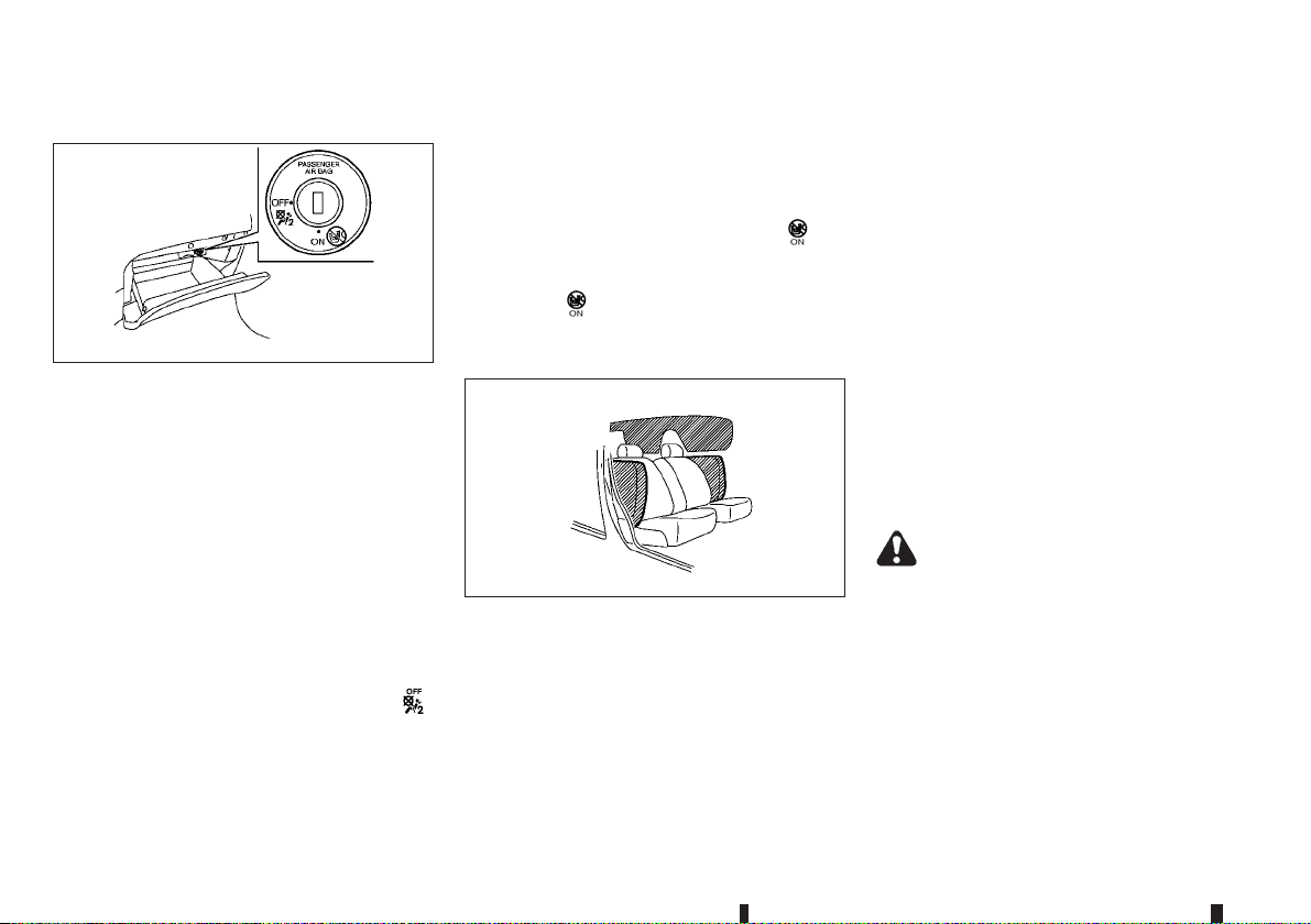
Front passenger air bag switch:
JVR0365XZ
The front passenger air bag can be turned off with
the front passenger air bag switch located in the
glove box.
To turn off the front passenger air bag:
1. Place the ignition switch in the OFF position.
2. Open the glove box and insert the mechanical
key into the front passenger air bag switch. For
the mechanical key usage, see “Mechanical key”
in the “3. Pre-driving checks and adjustments”
section.
3. Push and turn the key to the OFF position.
4. Place the ignition switch in the ON position. The
front passenger air bag status OFF light
will illuminate and remain on.
To turn on the front passenger air bag:
1. Place the ignition switch in the OFF position.
2. Open the glove box and insert the mechanical
key into the front passenger air bag switch.
3. Push and turn the key to the ON position.
4. Place the ignition switch in the ON position. The
front passenger air bag status ON light
illuminate.
5. After 1 minute, the front passenger air bag status
ON light
will turn off.
will
Supplemental side-impact air bag
system
SSS0978Z
The supplemental side-impact air bag is located at
the outside of the front seats’ seatbacks.
The supplemental side-impact air bag system is designed to inflate in higher severity side collisions,
although it may inflate if the forces in another type of
collision are similar to those of a higher severity side
impact. It may not inflate in certain side collisions.
Vehicle damage (or lack of it) is not always an indication of proper supplemental side-impact air bag
system operation.
Supplemental curtain side-impact air
bag system
The supplemental curtain side-impact air bag is located at the roof rails.
The supplemental curtain side-impact air bag system is designed to inflate in higher severity side collisions, although it may inflate if the forces in another
type of collision are similar to those of a higher severity side impact. It may not inflate in certain side
collisions. Vehicle damage (or lack of it) is not always an indication of proper supplemental curtain
side-impact air bag system operation.
PRE-TENSIONER SEAT BELT
SYSTEM
WARNING
The pre-tensioner seat belt cannot be reused
•
after activation. It must be replaced together
with the retractor and buckle as a unit.
If the vehicle becomes involved in a collision
•
but the pre-tensioner is not activated, be sure
to have the pre-tensioner system checked
and, if necessary, replaced by a NISSAN
dealer or qualified workshop.
1-38 Safety — seats, seat belts and supplemental restraint system
Page 61

No unauthorised changes should be made to
•
any components or wiring of the pre-tensioner
seat belt system. This is to prevent accidental
activation of the pre-tensioner seat belt or
damage to the pre-tensioner seat belt system.
Work around or on the pre-tensioner seat belt
•
system should be done bya NISSAN dealeror
qualified workshop. The SRS wiring should
not be modified or disconnected. Unauthorised electrical test equipment and probing
devices should not be used on the pre-tensioner seat belt system.
If you need to dispose of the pre-tensioner
•
seat belt system, or scrap the vehicle, contact
a NISSAN dealer or qualified workshop. Correct pre-tensioner disposal procedures are
set forth in the appropriate NISSAN Service
Manual. Incorrect disposal procedures could
cause personal injury.
The pre-tensioner is encased with the front seat
belt’s retractor and anchor. These seat belts are
used the same as conventional seat belts.
When the pre-tensioner seat belt activates, a fairly
loud noise may be heard, followed by the release of
smoke. This smoke is not harmful and does not indicate a fire. Care should be taken not to inhale it, as
it may cause irritation and choking. Those with a history of a breathing condition should get fresh air
promptly.
REPAIR AND REPLACEMENT
PROCEDURE
WARNING
Once the air bags have been inflated, the air
•
bag modules will not function and must be
replaced. The air bag modules must be replaced by a NISSAN dealer or qualified workshop. The inflated air bag modules cannot be
repaired.
The air bag systems should be inspected by a
•
NISSAN dealer or qualified workshop if there
is any damage to the front end portion of the
vehicle.
If you need to dispose of the SRS or scrap the
•
vehicle, contact a NISSAN dealer or qualified
workshop. Correct disposal procedures are
set forth in the appropriate NISSAN Service
Manual. Incorrect disposal procedures could
cause personal injury.
The air bags and pre-tensioner seat belts are designed to activate on a one-time-only basis. As a
reminder, unless the SRS air bag warning light is
damaged, the SRS air bag warning light remains
illuminated after inflation has occurred. The repair
and replacement of the SRS should be done only by
a NISSAN dealer or qualified workshop.
When maintenance work is required on the vehicle,
information about the air bags, pre-tensioner seat
belts and related parts should be pointed out to the
person performing the maintenance. The ignition
switch should always be inthe LOCK positionwhen
working under the bonnet or inside the vehicle.
Safety — seats, seat belts and supplemental restraint system 1-39
Page 62

2 Instruments and controlsInstruments and controls
Meters and gauges.................................................. 2-2
Speedometer and odometer ............................... 2-2
Tachometer ........................................................ 2-2
Engine coolant temperature gauge...................... 2-3
Fuel gauge ......................................................... 2-3
Instrument brightness control.............................. 2-3
Xtronic Continuously Variable Transmission
(CVT) position indicator (where fitted)................. 2-4
Warning lights, indicator lights and audible
reminders ................................................................ 2-5
Checking bulbs .................................................. 2-6
Warning lights .................................................... 2-6
Indicator lights.................................................... 2-10
Audible reminders............................................... 2-13
Vehicle information display....................................... 2-14
How to use the vehicle information display .......... 2-14
Startup display.................................................... 2-14
Settings.............................................................. 2-14
Vehicle information display warnings and
indicators............................................................ 2-22
Oil control system (for diesel engine model)........ 2-28
Trip computer..................................................... 2-29
Clock and outside air temperature ...................... 2-31
Driver Attention Alert (where fitted) ..................... 2-32
Traffic Sign Recognition (TSR) (where fitted) ...... 2-33
Headlight and turn signal switch............................... 2-35
Headlight switch................................................. 2-35
Headlight aiming control ..................................... 2-37
Battery saver system........................................... 2-41
Headlight cleaner (where fitted) .......................... 2-41
Turn signal switch............................................... 2-41
Fog light switch ....................................................... 2-42
Front fog lights (where fitted).............................. 2-42
Rear fog light...................................................... 2-42
Wiper and washer switch ........................................ 2-43
Windscreen wiper and washer switch................. 2-43
Rain-sensing auto wiper system (where fitted)..... 2-44
Rear window wiper and washer switch ............... 2-45
Headlight cleaner switch (where fitted) ............... 2-46
Defogger switch ...................................................... 2-46
Horn........................................................................ 2-47
Windows................................................................. 2-47
Power windows.................................................. 2-47
Sunroof (where fitted).............................................. 2-49
Automatic sunroof and sunshade ........................ 2-49
Power outlets .......................................................... 2-51
Storage ................................................................... 2-52
Glove box........................................................... 2-52
Console box ....................................................... 2-52
Sunglasses holder .............................................. 2-52
Cup holders ....................................................... 2-52
Soft bottle holders .............................................. 2-53
Card holder........................................................ 2-54
Luggage hooks................................................... 2-54
Luggage compartment (where fitted) .................. 2-54
Coat hook .......................................................... 2-56
Tonneau cover (where fitted) .............................. 2-57
Roof rail (where fitted) ............................................. 2-57
Sun visors ............................................................... 2-58
Interior lights............................................................ 2-58
Page 63

Interior light switch ............................................. 2-58
Console light ...................................................... 2-58
Map lights........................................................... 2-58
Room light (where fitted)..................................... 2-59
Rear personal lights (where fitted)....................... 2-59
Vanity mirror light................................................ 2-59
Luggage room light............................................. 2-59
Battery saver system........................................... 2-59
Page 64
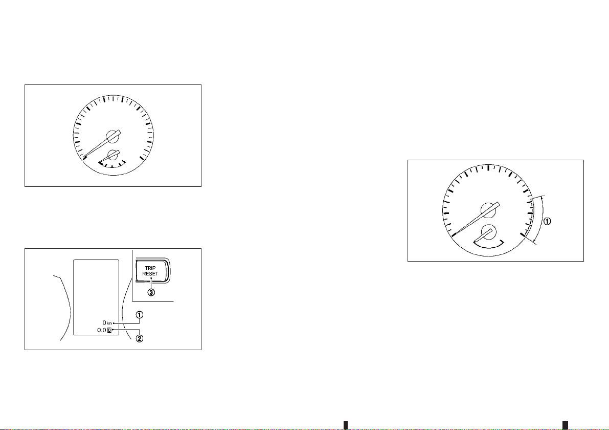
METERS AND GAUGES
SPEEDOMETER AND ODOMETER
Speedometer
JVI1006XZ
The speedometer indicates the vehicle speed (km/h
or MPH).
Distance to empty (dte — km or
mile)/Odometer
JVI0771XZ
Distance to empty (dte — km or mile):
The distance to empty (dte)
estimation of the distance that can be driven before
refuelling. The dte is constantly being calculated,
based on the amount of fuel in the fuel tank and the
actual fuel consumption.
The display is updated every 30 seconds.
The dte mode includes a lowrange warning feature.
If the fuel level is low, the warning is displayed on
the screen.
When the fuel level drops even lower, the dte display will change to “———”.
If the amount of fuel added is small, the distance
•
to empty shown just before the ignition switch is
placed in the “OFF” position may continue to be
displayed.
When driving uphill or rounding curves, the fuel
•
in thetank shifts, which may momentarilychange
the display.
Odometer/Twin trip odometer:
The odometer/twin trip odometer is displayed in the
vehicle information display when the ignition switch
is in the ON position.
The odometer
vehicle has been driven.
The twin trip odometer
individual trips.
j2 displays the total distance the
j1 provides you with an
j2 displays the distance of
Changing twin trip odometer display:
Push the TRIP RESET switch
instrument panel) to change the display as follows:
ODO → TRIP A → TRIP B → ODO
Resetting twin trip odometer:
Push the TRIP RESET switch
second to reset the trip odometer to zero.
j3 (located on the
j3 for more than 1
TACHOMETER
JVI0951XZ
The tachometer indicates the engine speed in revolutions per minute (rpm). Do not rev the engine
into the red zone
The red zone varies with models.
j1.
2-2 Instruments and controls
Page 65
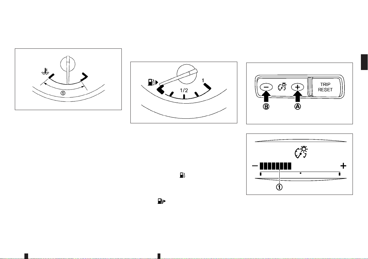
ENGINE COOLANT TEMPERATURE
GAUGE
JVI0999XZ
engine. (See “Engine overheat” in the “6. In
case ofemergency” sectionfor immediate action required.)
FUEL GAUGE
There is a small reserve of fuel in the tank when the
fuel gauge reads the empty (0) position.
INSTRUMENT BRIGHTNESS
CONTROL
The enginecoolant temperature gauge indicates the
engine coolant temperature.
The engine coolant temperature is normal when the
gauge needle points within the zone
the illustration.
The engine coolant temperature will vary with the
outside air temperature and driving conditions.
CAUTION
If thegauge indicates the engine coolant tem-
•
perature is near the hot (H) end of the normal
range, reduce vehicle speed to decrease the
temperature.
If the gauge is over the normal range, stop
•
the vehicle as soon as safely possible and let
the engine idle.
If the engine is overheated, continued opera-
•
tion of the vehicle may seriously damage the
j1 shown in
JVI0640XZ
The fuel gauge indicates the approximate fuel level
in the tank when the ignition switch is in the ON
position.
The gauge may move slightly during braking, turning, accelerating, or going up and down hills due to
movement of fuel in the tank.
The low fuel warning
information display when the fuel level in the tank is
getting low. Refuel as soon as it is convenient, preferably before the gauge reads 0 (empty).
The arrow,
cated on the right side of the vehicle.
CAUTION
Refuel before the gauge reads the empty (0) po-
sition.
, indicates the fuel-filler lid is lo-
appears on the vehicle
JVI0644XZ
JVI0661MZ
The instrument brightness control switch can be operated when the ignition switch is in the ON position. When the switch is operated, the vehicle information display switches to the brightness adjustment mode.
Instruments and controls 2-3
Page 66

Push the + side of the switch jA to brighten the
meter panel lights and instrument panel lights. The
bar
j1 moves to the + side.
Push the - side of the switch jB to dim the lights.
The bar
j1 moves to the − side.
The vehicle information display returns to the normal
display when the instrument brightness control
switch is not operated for more than 5 seconds.
XTRONIC CONTINUOUSLY
VARIABLE TRANSMISSION (CVT)
POSITION INDICATOR (where fitted)
The Xtronic CVT position indicator indicatesthe shift
lever position when the ignition switch is in the ON
position.
2-4 Instruments and controls
Page 67
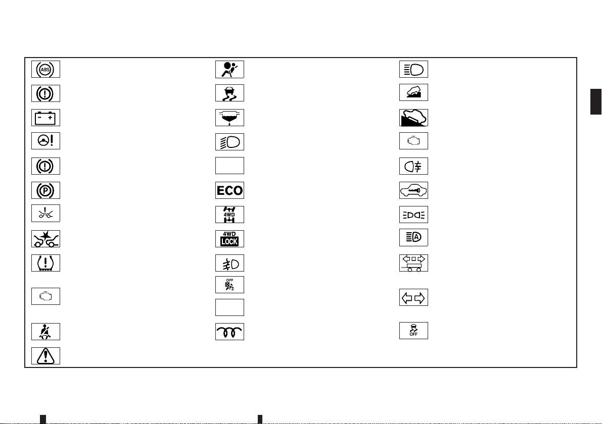
WARNING LIGHTS, INDICATOR LIGHTS AND AUDIBLE REMINDERS
Anti-lock Braking System (ABS) warning light
Brake warning light (red)
Charge warning light
Electric power steering warning light Dipped beam indicator light Malfunction Indicator Light (MIL)
Electronic parking brake system warning light (yellow)
Electronic parking brake warning light ECO mode system indicator light* Security indicator light
Forward emergency braking system
warning light*
Low tyre pressure warning light* Front fog lights indicator light* Trailer direction indicator light
Malfunction warning light (red) (diesel
engine model)
Seat belt warning light
Master warning light * where fitted
Supplemental Restraint System (SRS)
air bag warning light
Electronic Stability Programme (ESP)
warning light
Water-in-fuel-filter warning light (diesel
engine model)
Door lock indicator light* Rear fog light indicator light
Four-Wheel Drive (4WD) AUTO indicator light (4WD model)
Four-Wheel Drive (4WD) LOCK indicator light (4WD model)
Front passenger air bag status light Turn signals/hazard indicator lights
Glow plug indicator light (diesel engine
model)
High beam indicator light
Hill descent control system on indicator
light*
Hill Start Assist system on indicator
light
Small light indicator light
High beam assist indicator light*
Electronic Stability Programme (ESP)
off indicator light
Instruments and controls 2-5
Page 68
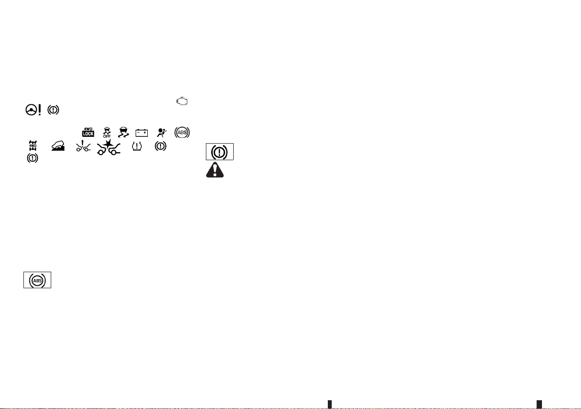
CHECKING BULBS
With all doors closed, apply the parking brake, fasten the seat belts and place the ignition switchin the
ON position without starting the engine. Where fitted, the following lights will illuminate:
, (red).
Where fitted, the following lightswill illuminatebriefly
and then turnoff:
, , , , , (red),
(yellow).
If any lightsfail toilluminate, itmay indicatea burnedout bulb or an open circuit in the electrical system.
Have the system checked, and if necessary repaired, by a NISSAN dealer or qualified workshop
promptly.
Some indicatorsand warnings are also displayed on
the vehicle information display between the speedometer and tachometer. (See “Vehicle information
display” later in this section.)
, ,
,
,
, ,
WARNING LIGHTS
Anti-lock Braking System (ABS)
warning light
When the ignition switch is in the ON position, the
Anti-lock Braking System (ABS) warning light illuminates and then turns off. This indicates the ABS is
operational.
If the ABS warning light illuminates while the engine
is running, or while driving, it may indicate the ABS
is not functioning properly. Have the system
checked by a NISSAN dealer or qualified workshop
promptly.
,
If an ABS malfunction occurs, the anti-lock function
is turned off. The brake system then operates normally, but without anti-lock assistance. (See “Brake
system” in the “5. Starting and driving” section.)
Brake warning light (red)
WARNING
If the brake fluid level is below the minimum
•
mark on the brake fluid reservoir, do not drive
the vehicle until the brake system has been
checked by a NISSAN dealer or qualified
workshop.
Even if you judge it to be safe, have your ve-
•
hicle towed because driving it could be dangerous.
Depressing the brake pedal without the en-
•
gine running and/or with a low brake fluid
level could increase the stoppingdistance and
require greater pedal travel distance and effort.
The brake warning light indicates a low brake fluid
level of the brake system and/or an Anti-lock Braking System (ABS) malfunction.
Low brake fluid warning indicator:
When the ignition switch is placed in the ON position, the brake warning light illuminates, and then
turns off (models equipped with electronic parking
brake system).
If the brake warning light illuminates while the engine is running, or while driving, and the parking
brake is released, it may indicate the brake fluid
level is low.
When the brake warning light illuminates while driving, stop the vehicle safely as soon as possible.
Stop the engine and check the brake fluid level. If
the brake fluid level is at the minimum mark, add
brake fluid as necessary. (See “Brake fluid” in the
“8. Maintenance and do-it-yourself” section.)
If the brake fluid level is sufficient, have the brake
system checked by a NISSAN dealer or qualified
workshop promptly.
Anti-lock Braking System (ABS) warning
indicator:
When the parking brake is released and the brake
fluid level is sufficient, if both the brake warning light
and the Anti-lock Braking System (ABS) warning
light illuminate, it may indicate the ABS is not functioning properly. Have the brake system checked,
and if necessary repaired, by a NISSAN dealer or
qualified workshop promptly. (See “Anti-lock Braking System (ABS) warning light” earlier in this section.)
2-6 Instruments and controls
Page 69
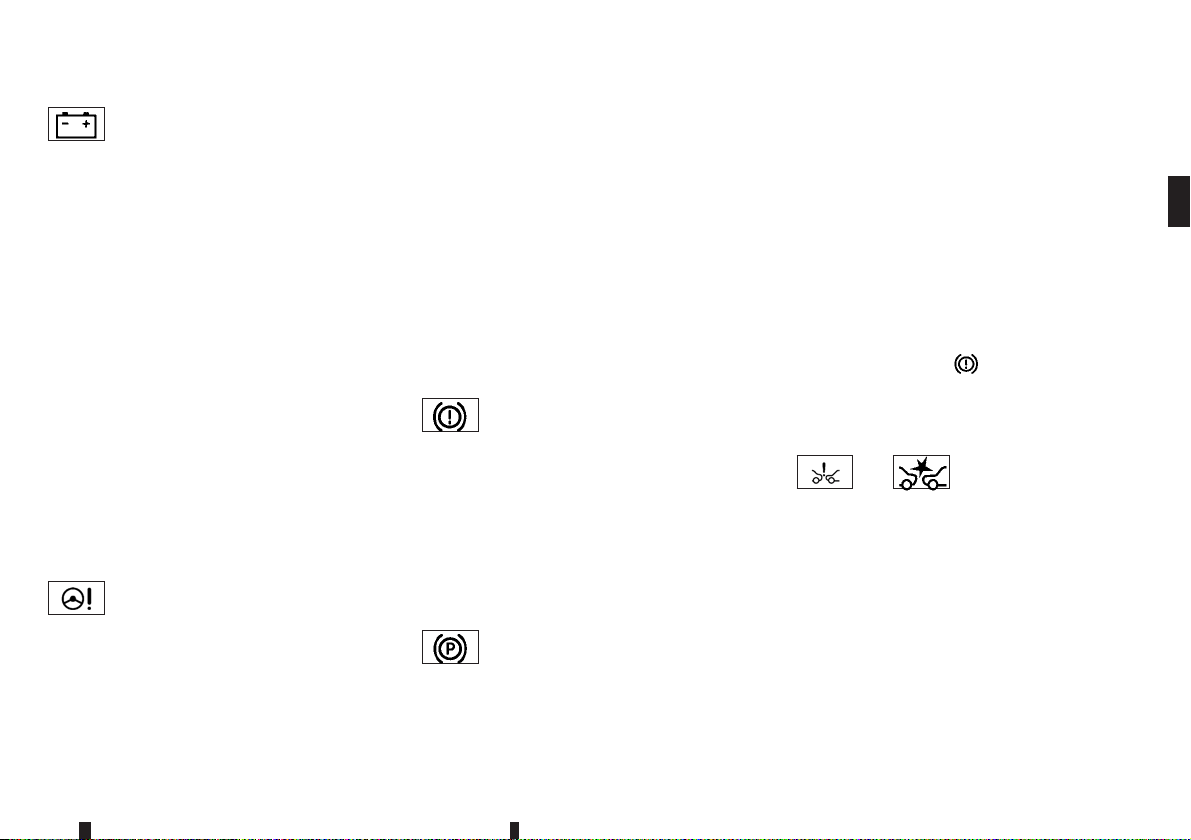
Charge warning light
When the ignition switch is in the ON position, the
charge warning light illuminates, and then turns off.
This indicates the charging system is operational.
If the charge warning light illuminates while the engine is running, or while driving, it may indicate the
charging system is not functioning properly and may
need servicing.
When the charge warning light illuminates while driving, stop the vehicle safely as soon as possible.
Stop the engine and check the alternator belt. If the
alternator belt isloose, brokenor missing,the charging system needs repair. (See “Drive belt” in the
“8. Maintenance and do-it-yourself” section.)
If the alternator belt appears to be functioning correctly but the charge warning light remains illuminated, have the charging system checked by a
NISSAN dealer or qualified workshop promptly.
CAUTION
Do not continue driving if the alternator belt is
loose, broken or missing.
Electric power steering warning
light
When the ignition switch is in the ON position, the
electric power steering warning light illuminates. After starting the engine, the electric power steering
warning light turns off. This indicates the electric
power steering system is operational.
If the electric power steering warning light illuminates while the engine is running, it may indicate the
electric power steering system is not functioning
properly and may need servicing. Have the electric
power steering systemchecked bya NISSAN dealer
or qualified workshop.
When the electric power steering warning light illuminates with the engine running, thepower assist to
the steering will cease operation but you will still
have control of the vehicle. At this time, greater
steering efforts are required to operate the steering
wheel, especially in sharp turns and at low speeds.
(See “Electric power steering system” in the
“5. Starting and driving” section.)
Electronic parking brake system
warning light (yellow)
The electronic parking brake system warning light
functions for the electronic parking brake system.
When the ignition switch is placed in the ON position, the light illuminates for a few seconds. If the
warning light illuminates at any other time, it may
indicate that the electronic parking brake system is
not functioning properly. Have the brake system
checked, and if necessary repaired, by a NISSAN
dealer promptly.
Electronic parking brake
warning light
The electronic parking brake warning light indicates
that the electronic parking brake system is operating.
When the ignition switch is placed in the ON position, the electronic parking brake warning light illuminates. When the engine is started and theparking
brake is released, the warning light turns off.
If the parking brake is not fully released, the electronic parking brake warning light remains on. Be
sure that the electronic parking brake warning light
has turned off before driving (see “Parking brake” in
the “3. Pre-driving checks and adjustments” section).
If the electronic parking brake warning light illuminates or flashes while the electronic parking brake
system warning light
may indicate that the electronic parking brake system is not functioning properly. Have the brake system checked, and if necessary repaired, by a
NISSAN dealer or qualified workshop promptly.
(yellow) illuminates, it
or Forward emergency
braking system
warning light (where
fitted)
When the ignition switch is in the ON position, the
forward emergency braking system warning light
illuminates and then turns off.
This light illuminates when the forward emergency
braking system is set to OFF on the vehicle information display.
Instruments and controls 2-7
Page 70

If the light illuminates when the forward emergency
braking system is ON, it may indicate that the system is unavailable. See “Forward emergency braking system (where fitted)” in the “5. Starting and
driving” section for more details.
Low tyre pressure warning light
(where fitted)
When the ignition switch is in the ON position, the
low tyre pressure warning light illuminates and then
turns off. This indicates that the low tyre pressure
warning system is operational.
This light illuminates if there is low tyre pressure or
a tyre pressure warning system malfunction.
The Tyre Pressure Monitoring System(TPMS) monitors the tyre pressure of all tyres except the spare.
Low tyre pressure warning:
If the vehicle is being driven with low tyre pressure,
the low tyre pressure warning light will illuminate.
When the lowtyre pressurewarning light illuminates,
you should stop and adjust the tyre pressure to the
recommended COLD tyre pressure shown on the
tyre placard. Use a tyre pressure gauge to check
the tyre pressure. The low tyre pressure warning
light may not automatically turn off when the tyre
pressure is adjusted. After the tyre is inflated to the
recommended pressure, reset the tyre pressures
registered in your vehicle and then drive the vehicle
at speeds above 25 km/h (16 MPH). These operations are required to activate the TPMS and turn off
the low tyre pressure warning light.
Depending on a change in the outside temperature,
the low tyre pressure warning light may illuminate
even if the tyre pressure has been adjusted properly. Adjust the tyre pressure to the recommended
COLD tyre pressure again when the tyres are cold,
and reset the TPMS.
If the low tyre pressure warning light still continues
to illuminate after the resetting operation, it may indicate thatthe TPMS is not functioningproperly. Have
the system checked by a NISSAN dealer or qualified workshop.
For additionalinformation, see “Tyre Pressure Monitoring System (TPMS)(where fitted)”in the “5. Starting and driving” section.
TPMS malfunction:
If the TPMS is not functioning properly, the low tyre
pressure warning light will flash for approximately 1
minute when the ignition switch is placed in the ON
position. The light will remain on after the 1 minute.
Have the system checked by a NISSAN dealer or
qualified workshop.
For additionalinformation, see “Tyre Pressure Monitoring System (TPMS)(where fitted)”in the “5. Starting and driving” section.
WARNING
If the light does not illuminate with the igni-
•
tion switch placed in the ON position, have
the vehicle checked by a NISSAN dealer as
soon as possible.
If thelight illuminateswhile driving, avoid sud-
•
den steering manoeuvres or abrupt braking,
reduce vehicle speed, pull off the road to a
safe location and stop the vehicle as soon as
possible. Driving withunder-inflated tyresmay
permanently damage the tyres and increase
the likelihood of tyre failure. Serious vehicle
damage could occur and may lead to an accident and could result in serious personal injury. Check the tyre pressure for all four tyres.
Adjust the tyre pressure to the recommended
COLD tyre pressure shown on the tyre placard to turn the low tyre pressure warning light
off. If you have a flat tyre, replace it with a
spare tyre as soon as possible.
After adjusting the tyre pressure, be sure to
•
reset the TPMS. Otherwise, the TPMS will not
warn of low tyre pressure.
When a spare tyre is mounted or a wheel is
•
replaced, the TPMS will not function and the
low tyre pressure warning light will flash for
approximately 1 minute. The light will remain
on after the 1 minute. Contact your NISSAN
dealer or qualified workshop as soon as possible for tyre replacement and/or system resetting.
Replacing tyres with those notoriginally speci-
•
fied by NISSAN could affect the proper operation of the TPMS.
2-8 Instruments and controls
Page 71
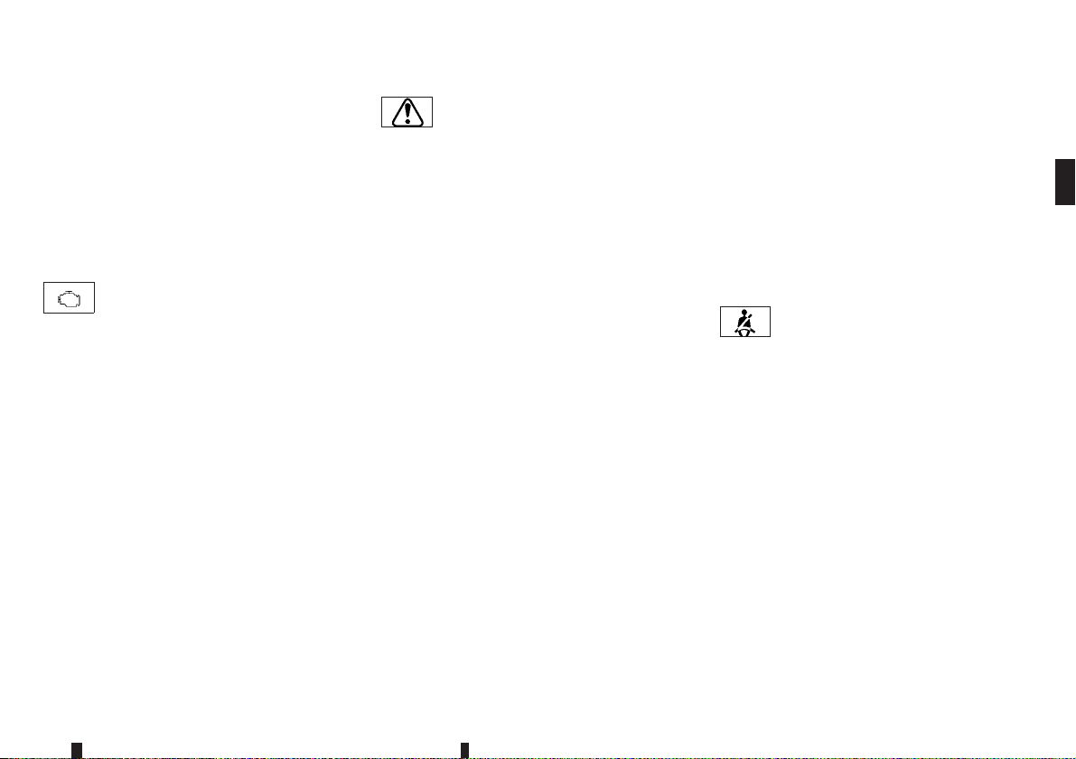
CAUTION
The TPMS is not a substitute for the regular
•
tyre pressurecheck. Be sure to check the tyre
pressure regularly.
If the vehicle is being driven at speeds of less
•
than 25 km/h (16 MPH), the TPMS may not
operate correctly.
Be sure to install the specified size of tyres to
•
all four wheels correctly.
Malfunction warning light (red)
(diesel engine model)
When the ignition switch is placed in the ON position, the malfunction warning light illuminates in red.
This means that the system is operational. After
starting the engine, the warning light turns off.
For the orange Malfunction Indicator Light (MIL),
see “ Malfunction Indicator Light (MIL)” later in this
section for details.
If the malfunction warning light (red) illuminates continuously while the engine is running, it may indicate
an engine control system malfunction. Have your
vehicle inspected by a NISSAN dealer or qualified
workshop. You do not need to have your vehicle
towed to the dealer.
CAUTION
Continuing vehicle operation without proper ser-
vicing of the engine control system could lead to
poor driveability, reduced fuel economy, and
damage to the engine control system, which may
affect the vehicle’s warranty coverage.
Master warning light
When the ignition switch is in the ON position, the
master warning light illuminates if any of the following are displayed on the vehicle information display.
Steering lock release malfunction indicator
•
No Key detected warning (where fitted)
•
Key ID incorrect warning (where fitted)
•
Shift to Park warning (Xtronic (CVT) Continu-
•
ously Variable Transmission models)
Door/back door open warning
•
Low fuel warning
•
Release parking brake warning
•
Engine start operation indicator (Xtronic (CVT)
•
Continuously Variable Transmission models)
Key System Fault warning (where fitted)
•
Low Tyre Pressure warning (where fitted)
•
Tyre pressure system fault (where fitted)
•
CVT System Fault warning (Xtronic (CVT) Con-
•
tinuously Variable Transmission models)
Low oil pressure Stop vehicle warning (where
•
fitted)
4WD system fault warning (where fitted)
•
4WD High Temp. Stop vehicle warning (where
•
fitted)
Tyre size incorrect warning (where fitted)
•
Key battery low warning (where fitted)
•
Battery Voltage Low Charge Battery warning
•
Headlight system fault warning (where fitted)
•
Chassis control system fault warning (where fit-
•
ted)
Second row seat belt warning (where fitted)
•
Other warning
•
See “Vehicle information display” later in this section.
Seat belt warning light
When the ignition switch is in the ON position, the
front seat belt warning light on the meter illuminates.
The light will continue to illuminate until the driver’s
and/or passenger’s seat belts are fastened. (See
“Seat belts” in the “1. Safety — seats, seat belts
and supplemental restraint system” section.)
When the vehicle speed exceeds 15 km/h (10
MPH), the light will blink and the chime will sound
unless the front seat belt is securely fastened. The
chime will continue to sound for about 95 seconds
until the seat belt is fastened. (See “Seat belts” in
the “1. Safety — seats, seat belts and supplemental
restraint system” section.)
For second row seats, see “Vehicle information display warnings and indicators” later in this section.
Instruments and controls 2-9
Page 72
Supplemental Restraint System
(SRS) air bag warning light
When the ignition switch is in the ON position, the
Supplemental RestraintSystem (SRS) air bag warning light illuminates for about 7 seconds and then
turns off. This indicates the SRS air bag system is
operational.
If any of the following conditions occur, the SRS air
bag system and/or pre-tensioner seat belt need servicing. Have the system checked, and if necessary
repaired, by a NISSAN dealeror qualified workshop
promptly.
The SRS air bag warning light remains illumi-
•
nated after about 7 seconds.
The SRS air bag warning light flashes intermit-
•
tently.
The SRS air bag warning lightdoes not come on
•
at all.
Unless checked and repaired, the SRS air bag system and/or pre-tensioner seat belt may not function
properly. (See “SRS air bag warning light” in the
“1. Safety — seats, seat belts and supplemental
restraint system” section.)
Electronic Stability Programme
(ESP) warning light
When the ignition switch is in the ON position, the
Electronic Stability Programme (ESP) warning light
illuminates and then turns off.
The warning light blinks when the ESP system is
operating.
When the warning light blinks while driving, the driving condition is slippery and the vehicle’s traction
limit is about to be exceeded.
If the ESP warning light illuminates while the engine
is running or while driving, it may indicate that the
ESP system is not functioning properly and may
need servicing. Have the system checked, and if
necessary repaired, by a NISSAN dealer or qualified workshop promptly. If a malfunction occurs, the
ESP functionis turned off, but the vehicle isstill drivable. (See “Electronic Stability Programme (ESP)
system” in the “5. Starting and driving” section.)
Water-in-fuel-filter warning light
(diesel engine model)
If the water-in-fuel-filter warning light illuminates
while the engine is running, contact a NISSAN
dealer or qualified workshop as soon as possible.
CAUTION
Continuing vehicle operation without properly
draining could cause serious damage to the engine.
INDICATOR LIGHTS
Dipped beam indicator light
The dipped beam indicator light illuminates when
the headlight low beam is on. (See “Headlight
switch” later in this section.)
Door lock indicator light
(where fitted)
The door lock indicator light, located on the instrument panel, illuminates when all the doors are
locked.
With the ignition switch in the ON position, the
•
door lock indicator light will illuminate and stay
on when the doors are locked using the power
door lock switch.
With the ignition switch in the OFF or LOCK
•
position, the door lock indicator light will operate
as follows:
– When the doors are locked with the power
door lock switch, the door lock indicator light
will illuminate for 30 minutes.
– When the doors are locked by pushing the
LOCK button (on the integrated keyfob or
Intelligent Key) or the request switch (Intelligent Key system equipped models), the door
lock indicator light will illuminate for 1 minute.
The door lock indicator light turns off when any door
is unlocked.
For locking or unlocking doors, see “Door locks” in
the “3. Pre-driving checks and adjustments” section.
2-10 Instruments and controls
Page 73
ECO mode system indicator
light (where fitted)
The ECO mode indicator light illuminates when the
ECO mode system is turned on.
(See “ECO mode system (where fitted)” in the
“5. Starting and driving” section.
Four-Wheel Drive (4WD) AUTO
indicator light (4WD model)
When the ignition switch is in the ON position, the
Four-Wheel Drive (4WD) AUTO indicator light illuminates and then turns off.
When selecting 4WD AUTO mode while the engine
is running, the 4WD AUTO indicator light illuminates. (See “Four-Wheel Drive (4WD) (where
fitted)” in the “5. Starting and driving” section.)
Four-Wheel Drive (4WD) LOCK
indicator light (4WD model)
When the ignition switch is in the ON position, the
Four-Wheel Drive (4WD) LOCK indicator light illuminates and then turns off.
When selecting 4WD LOCK mode while the engine
is running, the 4WD LOCK indicator light illuminates simultaneously with the 4WD AUTO indicator
light illuminating. (See “Four-Wheel Drive (4WD)
(where fitted)” in the “5. Starting and driving” section.)
CAUTION
Do not drive on dry hard surface roads in the
LOCK mode.
Front fog lights indicator light
(where fitted)
The front fog lights indicator light illuminates when
the front fog lights are on. (See “Front fog lights
(where fitted)” later in this section.)
/ Front passenger air
bag status light
The front passenger air bag status light ( ) located on the instrument panel will illuminate when
the front passenger air bag is turned off with the
front passenger air bag switch. When the front passenger air bag is turned on, the front passenger air
bag status light (
For more details, see “Front passenger air bag status light” in the “1. Safety — seats, seat belts and
supplemental restraint system” section.
) will illuminate.
Glow plug indicator light (diesel
engine model)
When the ignition switch is in the ON position, the
glow plug indicator light illuminates and turns off
after the glow plugs have warmed up.
If the glow plugs have already warmed up, the glow
plug indicator flashes briefly and then turns off.
High beam assist indicator light
(where fitted)
The indicator light illuminates when the headlights
come on while the headlight switch is in the AUTO
position with the high beam selected. This indicates
that the highbeam assistsystem isoperational. (See
“High beam assist (where fitted)” later in this section.)
High beam indicator light
The high beam indicator light illuminates when the
headlight high beam is on. The indicator turns off
when the low beam is selected. (See “Headlight
switch” later in this section.)
Hill descent control system on
indicator light (where fitted)
When the ignition switch is placed in the ON position the hill descent control system on indicator light
illuminates briefly and then turns off. This indicates
that the hill descent control system is operational.
The light illuminates when the hill descent control
system is activated.
If the hill descent control switch is on and the indicator light blinks, the system is not engaged.
If the indicator light doesnot illuminate or blink when
the hill descent control switch is on, the system may
not be functioning properly. Have the system
checked bya NISSANdealer or qualified workshop.
For additional information, see “Hill descent control
system (where fitted)”in the“5. Startingand driving”
section.
Instruments and controls 2-11
Page 74
Hill Start Assist system on
indicator light (where fitted)
The light illuminates when the conditions of the hill
start assist system are satisfied when the vehicle is
stopped on a hill.
Then, the light blinks when the brake pedal is released, which indicates that the hill start assist system is activated.
For additional information, see “Hill Start Assist
system” in the “5. Starting and driving” section.
Malfunction Indicator Light (MIL)
CAUTION
Continuing vehicle operation without proper
•
servicing of the engine control system and/or
Xtronic (CVT) Continuously Variable Transmission could lead to poor driveability, reduced fuel economy, and damage to the engine control system and/or Xtronic CVT system, which may affect the vehicle’s warranty
coverage.
Incorrect setting of the engine control system
•
may lead to non-compliance of local and national emission laws and regulations.
When the ignition switch is in the ON position, the
Malfunction Indicator Light (MIL) illuminates. After
starting the engine, the MIL turns off. This indicates
that the engine control system and/or Xtronic CVT
system is operational.
If the MIL illuminates while the engine is running, it
may indicate that the engine control system is not
functioning properly and may need servicing. Have
the vehicle checked, and if necessary repaired, by a
NISSAN dealer or qualified workshop promptly.
If the MIL blinks (where fitted) while the engine is
running, it may indicate a potential malfunction inthe
emission control system. In this case, the emission
control system may not function properly and may
need servicing. Have the system checked, and if
necessary repaired, by a NISSAN dealer or qualified workshop promptly.
Precautions:
To reduce or avoid possible damage to the engine
control system when the MIL blinks:
Avoid driving at speeds above 70 km/h (43
•
MPH).
Avoid sudden acceleration or deceleration.
•
Avoid going up steep uphill grades.
•
Avoid carrying or towing unnecessary loads.
•
Rear fog light indicator light
The rear fog light indicator light illuminates when the
rear fog light is on. (See “Fog light switch” later in
this section.)
Security indicator light
The security indicator light blinks when the ignition
switch is in the LOCK, OFF position. This function
indicates the security system* equipped on the vehicle is operational. (* immobilizer)
If security system is malfunctioning, this light will
remain on while the ignition switch is in the ON position. (See “Security system” in the “3. Pre-driving
checks and adjustments” section for additional information.)
Small light indicator light
The light illuminates when the headlight switch is
turned to the
position.
Trailer direction indicator light
The light will illuminate whenever an additional electrical load is detected by the direction indicator system.
For additional information, see “Trailer towing” in
the “5. Starting and driving” section.
Turn signals/hazard indicator
lights
The turn signals/hazard indicator lights blink when
the turn signal switch or hazard indicator flasher
switch is turned on. (See “Turn signal switch” later
in this section or “Hazard indicator flasher switch” in
the “6. In case of emergency” section.)
Electronic Stability Programme
(ESP) off indicator light
When the ignition switch is in the ON position, the
Electronic Stability Programme (ESP) off indicator
light illuminates and then turns off.
The ESP off indicator light illuminates when theESP
off switch is pushed to the OFF position.
2-12 Instruments and controls
Page 75

When the ESP off switch is pushed to the OFF
position, the ESP system is turned off.
For details, see “Electronic Stability Programme
(ESP) system” in the “5. Starting and driving” section.
AUDIBLE REMINDERS
Brake pad wear warning
The disc brake pads have audible wear warnings.
When a brake padrequires replacement,it willmake
a high pitched scraping sound when the vehicle is in
motion. This scraping sound will first occur only
when the brakepedal isdepressed. Aftermore wear
of the brake pad, the sound will always be heard
even if the brake pedal is not depressed. Have the
brakes checked as soon as possible if the wear
warning sound is heard.
Have the system checked, and if necessary repaired, by a NISSAN dealer or qualified workshop
promptly. (See “Brakes” in the “8. Maintenance and
do-it-yourself” section.)
Intelligent Key buzzer (where fitted)
The Intelligent Key buzzer sounds if any one of the
following improper operations is found.
The ignition switch is not returned to the LOCK
•
position when locking the doors.
The Intelligent Key is left inside the vehicle when
•
locking the doors.
Any doors are not closed securely when locking
•
the doors.
When the buzzer sounds, be sure to check both the
vehicle and the Intelligent Key. (See “Intelligent Key
system (where fitted)” in the “3. Pre-driving checks
and adjustments” section.)
Light reminder chime
The chime will sound if the driver’s side door is
opened while the headlight switch is in either the
or position and the ignition switch is in
the OFF or LOCK position.
Be sure to turn the light switch to the OFF or AUTO
(where fitted) position when you leave the vehicle.
Parking brake reminder chime
The chime will sound if the vehicle is driven at more
than 4 km/h (2 MPH) with the parking brake applied. Stop the vehicle and release the parking
brake.
Stop/Start System reminder buzzer
(where fitted)
The engine will shift to the normal stopped state if
any of the following operations is made during Stop/
Start System activation, and the Stop/Start System
buzzer will sound if:
The driver’s seat belt is unfastened and the driv-
•
er’s door is open (MT models).
The vehicle engine bonnet is open.
•
Close the bonnet or the driver’s door, or fasten the
seat belt then restart the engine using the ignition
switch.
For more information, see “Stop/Start System
(where fitted)” in the “5. Starting and driving” section.
Instruments and controls 2-13
Page 76
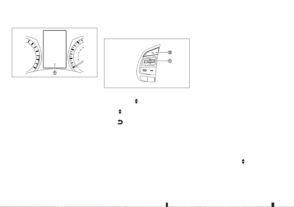
VEHICLE INFORMATION DISPLAY
JVI0641XZ
The vehicle information display j1 is located be-
tween the tachometer and the speedometer. It displays such items as:
Vehicle settings
•
Trip computer information
•
Driver Assistance (where fitted)
•
Speed limiter information (where fitted)
•
Cruise control system information (where fitted)
•
Intelligent Key operation information (where fit-
•
ted)
Audio information (where fitted)
•
Navigation - turn by turn (where fitted)
•
Indicators and warnings
•
Tyre pressure information (where fitted)
•
Chassis Control
•
Other information
•
HOW TO USE THE VEHICLE
INFORMATION DISPLAY
JVI0887XZ
The vehicle information display can be changed using theswitches
the steering wheel.
and <ENTER>j1 located on
j1— - navigate through the items in vehicle
information display
j2—
- go back to the previous menu
STARTUP DISPLAY
When the ignition switch is placed in the ON position, the screens that display in the vehicle information display include:
Trip computer
•
Fuel economy
•
Warnings
•
Warnings will only display if there are any present.
For more information on warnings and indicators,
see “Vehicle information display warnings and
indicators” later in this section.
To control what items display in the vehicle information display, see “Settings” later in this section.
SETTINGS
The setting mode allows you to change the information displayed in the vehicle information display:
[Driver Assistance] (where fitted)
•
[Clock]
•
[Display Settings]
•
[Vehicle Settings]
•
[Maintenance]
•
[Alert]
•
[Tyre Pressures] (where fitted)
•
[Units]
•
[Language] (where fitted)
•
[Factory Reset]
•
Driver Assistance (where fitted)
To change the status, warnings or turn on or off any
of the systems/warnings displayed in the [Driver Assistance] menu, use the
and the <ENTER>
[Driving Aids]
•
[Driver Attention]
•
j1 to change a menu item:
switch j1 to select
2-14 Instruments and controls
Page 77

[Traffic Sign]
•
[Parking Aids]
•
[Chassis Control]
•
Driving Aids:
To change the status, warnings or turn on or off any
of the systems/warnings displayed in the [Driving
Aids] menu, use the
the <ENTER>
[Lane]
•
– Lane Departure Warning (LDW) ON/OFF
[Blind Spot]
•
– Blind Spot Warning (BSW) ON/OFF
[Emergency Brake]
•
– Emergency Brake ON/OFF
Driver Attention:
[Driver Attention] ON/OFF
Traffic Sign:
[Traffic Sign] ON/OFF
Parking Aids:
To change the status or turn on or off any of the systems displayed in the [Parking Aids] menu, use the
change a menu item:
[Moving Object]
•
– Moving Object Detection (MOD) ON/OFF
j1 to change a menu item:
switch j1 to select and the <ENTER> j1to
switch j1 to select and
[Front Sensor]
•
– Front parking sensor ON/OFF
[Rear Sensor]
•
– Rear parking sensor ON/OFF
[Display]
•
– Parking sensor display ON/OFF
[Volume]
•
– Parking sensor buzzer volume [Low]/[Med.]/
[High]
[Range]
•
– Parking sensor detection range [Far]/[Mid.]/
[Near]
For more details, see “Around view monitor (where
fitted)” in the “4. Display screen, heater and air conditioner, and audio system” section.
Chassis Control:
To change the status, warnings or turn on or off any
of the systems/warnings displayed in the [Chassis
Control] menu, use the
and the <ENTER>
[Trace Control]
•
– For more details, see “Active Trace Control”
in the “5. Starting and driving” section.
j1 to change a menu item:
switch j1 to select
[Engine Brake] (where fitted)
•
– For more details, see “Active Engine Brake
(Xtronic Continuously Variable Transmission
(CVT) model)” in the “5. Starting and driving”
section.
Clock
For models without navigation or audio system:
Set Clock:
The clock settings can be changed using the
j1 and the <ENTER> j1 buttons.
12H/24H:
The time setting can be selected from 12 hour and
24 hour formats.
For models with navigation or audio system:
To set the clock, see “Clock” in the “4. Display
screen, heater and air conditioner, and audio
system” section, “SETUP button” in the “4. Display
screen, heater and air conditioner, and audio
system” section, or “Audio main operation” in the
“4. Display screen, heater and air conditioner, and
audio system” section in this manual or the separate
Navigation Owner’s Manual.
Display Settings
The meter settings allows the customer to choose
from the various meter selections.
The meter settings can be changed using the
j1 and the <ENTER> j1 buttons.
Instruments and controls 2-15
Page 78
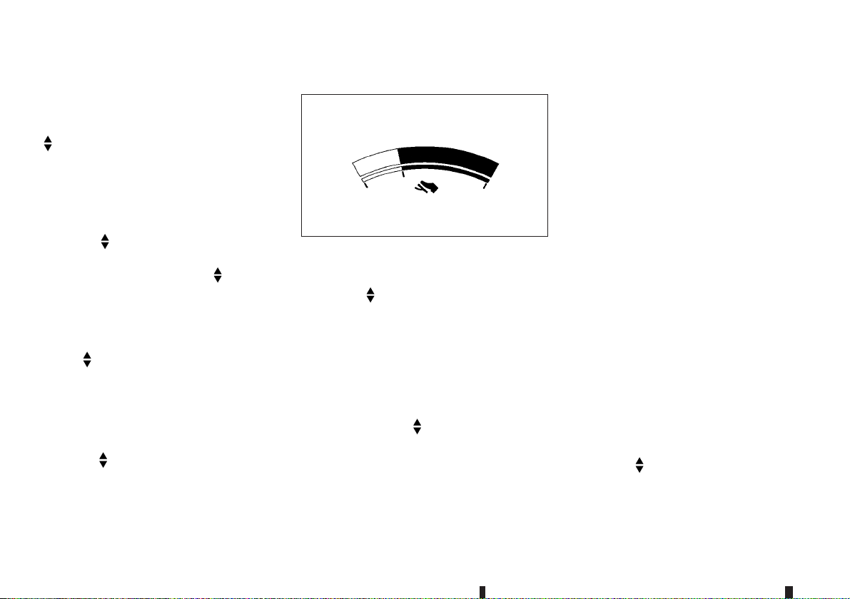
Contents Selection:
The items that display when the ignition switch is
placed in the ON position can be enabled/disabled.
To change the items that are displayed, use the
j1 to scroll and the <ENTER> j1 to select a
menu item.
Body Colour:
The colour of the vehicle that displays in the vehicle
information display when the ignition switch is
placed in the ON position can be changed.
1. Use the
selected, and press <ENTER>
2. Select the body colour using the switch j1
and press <ENTER>
ECO Mode Settings (where fitted):
This settingallows the customer to changethe ECO
mode system settings.
Use the
is selected, and press <ENTER>
[Eco Glow]:
This setting allows the customer to enable/disable
the ambient ECO indicator inthe vehicle information
display.
1. Use the
2. Press the <ENTER> j1 to turn ON/OFF the
ambient ECO in the vehicle information display.
switch j1 until [Body Colour] is
j1.
j1.
switch j1 until [ECO Mode Settings]
j1.
switch j1 to select [Eco Glow].
[Display]:
JVI0665XZ
This setting allows the customer to enable/disable
the ECO pedal guide function.
1. Use the
2. Press the <ENTER>
or [Fuel Econ.].
For more details, see “ECO mode system (where
fitted)” in the “5. Starting and driving” section.
Stop/Start (where fitted):
To change the status, warnings or turn on or off any
of the systems/warnings displayed in the [Stop/
Start] menu, use the
the <ENTER>
[Display]
•
– Stop/Start display ON/OFF
switch j1 to select [Display].
j1 to select [Pedal Guide]
switch j1 to select and
j1 to change a menu item:
[Trip CO2 Saving]
•
The Trip CO2 saving andengine stop timemode
shows the CO2 saving and engine stop time
since the last reset. The CO2 saving and engine
stop time can be reset by pushing <ENTER>
j1.
[Total CO2 Saving]
•
The Total CO2 saving and engine stop time
mode shows:
– The estimated CO2 exhaust emissions pre-
vented.
– The engine stop time thatthe enginehas been
stopped by the Stop/Start System.
NOTE
The TotalCO2 saving and engine stop time
values cannot be reset and show accumulated Stop/Start System information since
the vehicle was built.
ECO Drive Report (where fitted):
[Display]:
This setting allows the customer to enable/disable
the ECO Drive Report in the vehicle information display.
1. Use the
Report].
2. Press the <<ENTER>>
ECO management display in the vehicle information display.
switch j1 to select [ECO Drive
j1 to turn ON/OFF the
2-16 Instruments and controls
Page 79

[View History]:
This setting allows the customer to reset the past
history of the fuel economy and the best fuel
economy.
Welcome Effect:
You can choose whether or not to display the welcome screen when the ignition switch is placed in
the ACC or ON position. You can also choose the
following items to define how the welcome screen
looks:
[Dial and Pointer]
•
[Display Effect]
•
Select [Welcome Effect] using the
and press the <ENTER>
Use the
menu options and press the <ENTER>
each function ON/OFF.
switch j1 to navigate between the
j1 to select this menu.
switch j1
j1 to turn
Vehicle Settings
The vehicle settings allows the customer to change
settings for the following settings.
Lighting
•
Turn Indicator
•
Unlocking
•
Wipers
•
The vehicle settings can be changed using the
j1 , and the <ENTER> j1 switches.
Lighting:
The [Lighting] menu has the following options:
[Welcome Light]
•
The welcome lighting can be set to be ON or
OFF. From the [Lighting] menu, select [Welcome Light]. Use the <ENTER>
feature ON or OFF.
[Int. Lamp Timer]
•
The internal light timer can be set to be ON or
OFF. From the[Lighting] menu,select [Int. Lamp
Timer]. Use the <ENTER>
ON or OFF.
[Auto Lights]
•
The sensitivity of the automatic lighting can be
adjusted. From the [Lighting] menu, select [Auto
Lights]. Use the
<ENTER>
The following options are available:
– [On Earliest]
– [On Earlier]
– [Standard]
– [On Later]
[Headlight Off Delay] (where fitted)
•
The duration of the automatic headlights can be
changed from 0 to 180seconds. Fromthe [Lighting] menu, select [Headlight Off Delay]. Use the
<ENTER>
j1 to select the required sensitivity.
j1 to change the duration.
j1 to turn this
j1 to turn this feature
switch j1 and the
Turn Indicator:
The [3 Flash On] overtaking feature can beset to be
ON or OFF. From the [Turn Indicator] menu, select
[3 Flash On]. Use the <ENTER>
ture ON or OFF.
Unlocking:
There are the following options in the [Unlocking]
menu:
[I-Key Door Lock]
•
When this item is turned on, the request switch
on the door is activated. From the [Unlocking]
menu, select [I-Key Door Lock]. Use the
<ENTER> button to activate or deactivate this
function.
[Selective Unlock]
•
When this item is turned on, and the door handle
request switch on the driver’s or front passenger’s side door is pushed, only the corresponding door is unlocked. All the doors can be unlocked if the door handle request switch is
pushed again within 1 minute. When this item is
turned to off, all the doors will be unlocked when
the door handle request switch is pushed once.
From the [Unlocking] menu, select [Selective
Unlock]. Use the <ENTER> button to activate or
deactivate this function.
j1 to turn this fea-
Instruments and controls 2-17
Page 80
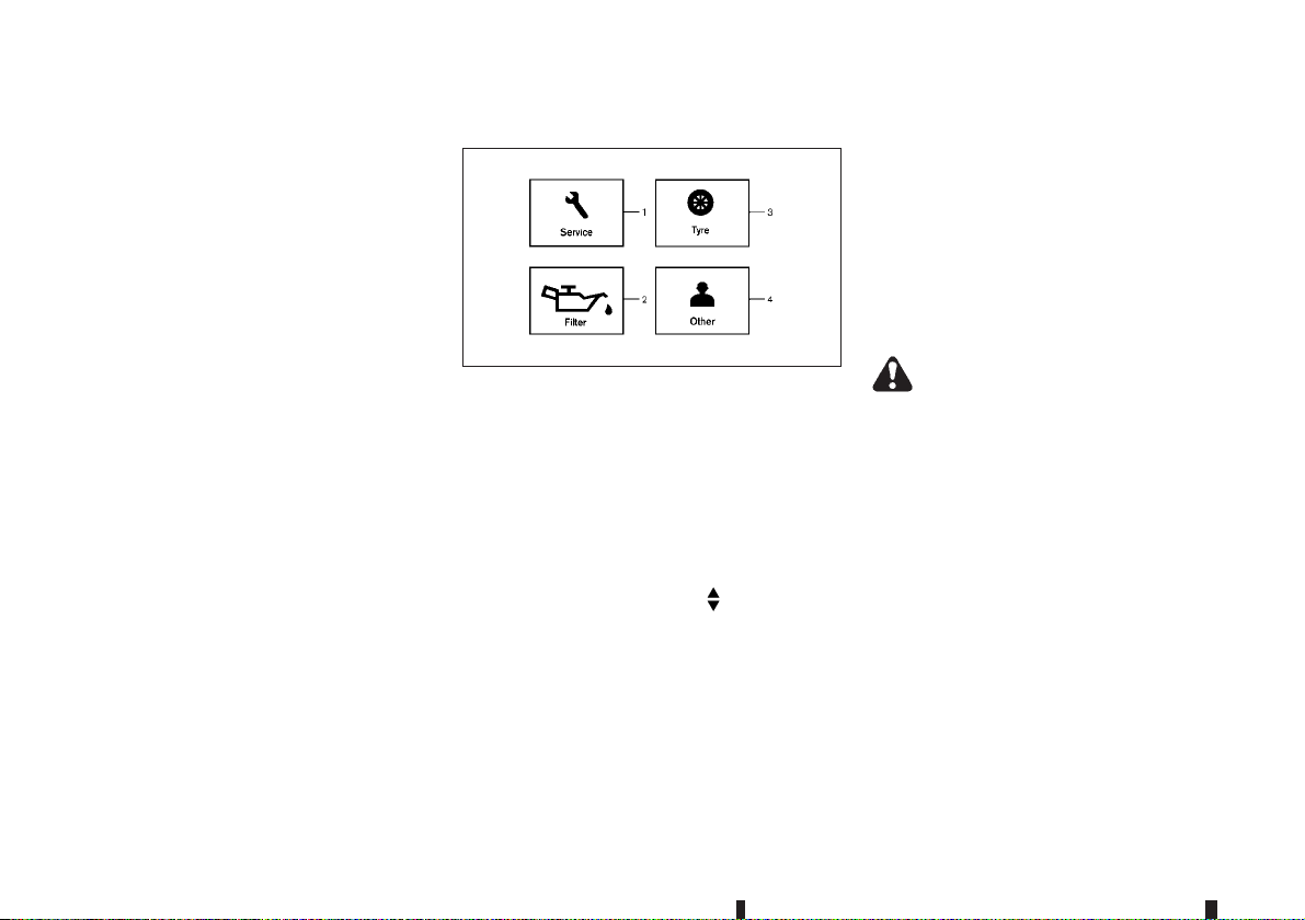
[Answer Bk. Horn] (where fitted)
•
When the answer back horn is on the horn will
chirp and the hazard indicators will flash once
when locking the vehicle with the Intelligent Key
or remote keyless entry function.
Wipers:
Speed Dependent (where fitted)
•
The [Speed Dependent]feature canbe activated
or deactivated. From the [Wipers] menu, select
[Speed Dependent]. Use the <ENTER>
turn this feature ON or OFF.
Rain Sensor (where fitted)
•
The [Rain Sensor] feature can be activated or
deactivated. From the [Wipers] menu, select
[Rain Sensor]. Use the <ENTER>
feature ON or OFF.
Reverse Link
•
The [Reverse Link] wiper feature can be set to
be ON or OFF. From the [Wipers] menu, select
[Reverse Link]. Use the <ENTER>
this feature ON or OFF.
Drip Wipe
•
The [Drip Wipe] feature can be set to be ON or
OFF. From the [Wipers] menu, select [Drip
Wipe]. Use the <ENTER>
ON or OFF.
j1 to turn this
j1 to turn
j1 to turn this feature
j1to
Maintenance
JVI0978XZ
1. Service
2. Filter (where fitted)
3. Tyre
4. Other
The maintenance mode allows you to set alerts for
the reminding of maintenance intervals. To change
an item:
Select [Maintenance]using the
press <ENTER>
Service:
This indicator appears when the customer set distance comes for changing the engine oil and filter.
You can set or reset the distance for checking or
replacing these items. For scheduled maintenance
items and intervals, see a separate maintenance
booklet.
j1.
switch j1 and
Filter (where fitted):
This indicator appears when the customer set distance comes for changing the oil filter. You can set
or resetthe distance for checking or replacing these
items. For scheduled maintenance items and intervals, see a separate maintenance booklet.
Tyre:
This indicator appears when the customer set distance comes for replacing tyres. You can set or
reset the distance for replacing tyres.
WARNING
The tyre replacement indicator is nota substitute
for regular tyre checks, including tyre pressure
checks. See “Changing tyres and wheels” in the
“8. Maintenance and do-it-yourself” section.
Many factors including tyre inflation, alignment,
driving habits and road conditions affect tyre
wear and when tyres should be replaced. Setting
the tyre replacement indicator for a certain driving distance does not mean your tyres will last
that long. Use the tyre replacement indicator as
a guide only and always perform regular tyre
checks. Failure to perform regular tyre checks,
including tyre pressure checks could result in
tyre failure. Serious vehicle damage could occur
and may lead to a collision, which could result in
serious personal injury or death.
Other:
This indicator appears when the customer set distance comes for checking or replacing maintenance
items other than the engine oil, oil filter and tyres.
2-18 Instruments and controls
Page 81

Other maintenance items can include such things
as air filter or tyre rotation. You can set or reset the
distance for checking or replacing the items.
Alert
This setting allows the customer to set alarms.
Select [Alert] using the
<ENTER>
Outside Temp. (where fitted):
This setting allows the customer to enable/disable
the alert for outside temperature in the vehicle information display.
1. Use the
2. Press <ENTER>
Timer:
This setting allows the customer to set an alert to
notify the driver that the set time has been reached.
1. Use the
2. Press the <ENTER>
3. To changethe timeramount, use the
j1.
switch j1 to select [Outside
Temp.].
j1 to turn the alert ON/OFF.
switch j1 to select [Timer].
switch j1 and press
j1.
switch
j1 and the <ENTER> j1 to save the selected
time amount.
Navigation (where fitted):
This setting allows the customer to enable/disable
the alert for navigation in the vehicle information display.
1. Use the
switch j1 to select [Navigation].
2. Press the <ENTER>
alert.
Phone (where fitted):
This setting allows the customer to enable/disable
the alert for navigation in the vehicle information display.
1. Use the
2. Press the <ENTER>
alert.
Mail (where fitted):
This setting allows the customer to enable/disable
the alert for navigation in the vehicle information display.
1. Use the
2. Press the <ENTER>
alert.
j1 to turn ON/OFF the
switch j1 to select [Phone].
j1 to turn ON/OFF the
switch j1 to select [Mail].
j1 to turn ON/OFF the
Tyre pressures (where fitted)
The settings in the [Tyre Pressures] menu are all
related to the Tyre pressure monitoring system
TPMS (See “Tyre Pressure Monitoring System
(TPMS) (where fitted)” in the “6. In case of
emergency” section, “Tyre Pressure Monitoring
System (TPMS) (where fitted)” in the “5. Starting
and driving” section and “Tyre Pressure Monitoring
System (TPMS) (where fitted)” in the “8. Maintenance and do-it-yourself” section).
Target Front
•
Target Rear
•
Tyre Pressure Unit
•
Calibrate
•
Target Front:
The [Target Front] tyre pressure is the pressure
specified for the front tyres on the tyre placard. (See
“Tyre Pressure Monitoring System (TPMS) (where
fitted)” in the “5. Starting and driving” section and
“Tyre placard” in the “9. Technical information” section).
Use the
select and change the value for the [Target Front]
tyre pressure.
Target Rear:
The [Target Rear] tyre pressure is the pressure
specified for the rear tyres on the tyre placard. (See
“Tyre Pressure Monitoring System (TPMS) (where
fitted)” in the “5. Starting and driving” section and
“Tyre placard” in the “9. Technical information” section).
Use the
select and change the value for the [Target Rear]
tyre pressure.
Tyre Pressure Unit:
The unit for tyre pressure that displays in the vehicle
information display can be changed to:
kPa
•
bar
•
psi
•
Kgf/cm2
•
j1 and the <ENTER> j1 buttons to
j1 and the <ENTER> j1 buttons to
Instruments and controls 2-19
Page 82
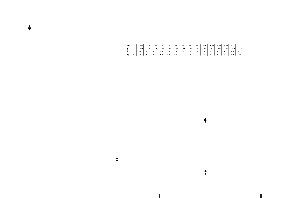
Use the j1 and the <ENTER> j1 buttons to
select and change the unit.
If necessary, refer to the following table to convert
between units.
JVI0938XZ
2-20 Instruments and controls
Calibrate:
The tyre pressure is affected by the temperature of
the tyre; the tyre temperature increases when the
car is driven. To be able to accurately monitor the
tyre airleakage and to prevent false TPMS warnings
due to changes in temperature, the TPMS system
uses temperature sensors in the tyres to perform
temperature compensation calculations.
On rare occasions it may be necessary to recalibrate
the TPMS system reference temperature. This operation should only be performed when the actual
tyre pressure has been adjusted, whilst the current
ambient temperature is significantly different to the
current calibration temperature. (See “Tyre Pressure Monitoring System (TPMS) (where fitted)” in
the “5. Starting and driving” section).
Use the
start or cancel the calibration process. While the
calibration process is active, the message: [Resetting tyre pressure system] will be displayed.
j1 , and the <ENTER> j1 switches to
Units (where fitted)
The units that are shown in the vehicle information
display can be changed:
Distance/Fuel
•
Tyre pressures
•
Temperature
•
Use the
select and change the units of the vehicle information display.
Distance/Fuel:
The unit for the mileage that displays in the vehicle
information display can be changed to:
km, l/100km
•
km, km/l
•
miles, MPG (UK)
•
Use the
select and change the unit.
j1 , and the <ENTER> j1 switches to
j1 and the <ENTER> j1 switches to
Page 83

Tyre pressures:
For more details, see “Tyre pressures (wherefitted)”
earlier in this section.
Temperature:
The temperature that displays in the vehicle information display can be changed from:
°C (Celsius)
•
°F (Fahrenheit)
•
Use the <ENTER>
j1 to toggle choices.
Language (where fitted)
The language of the vehicle information display can
be changed to:
English
•
French
•
German
•
Italian
•
Portuguese
•
Dutch
•
Spanish
•
Turkish
•
Russian
•
Use the j1 , and the <ENTER> j1 switches to
select and change the language of the vehicle information display. The language of the centre display/
navigation can be changed independently of the vehicle information display.
For models with navigation system, see “Vehicle
information and settings (models with navigation
system)” in the “4. Display screen, heater and air
conditioner, and audio system” section.
For models without navigation system, see “Audio
system (where fitted)” in the “4. Display screen,
heater and air conditioner, and audio system” section.
Factory Reset
The settings in the vehicle information display can
be reset back to the factory default. To reset the
vehicle information display:
1. Select [Factory Reset] using the
switch
j1 and press the <ENTER> j1.
2. Select [Yes] to return all settings back to default
by pressing the <ENTER>
j1.
Instruments and controls 2-21
Page 84

VEHICLE INFORMATION DISPLAY WARNINGS AND INDICATORS
2-22 Instruments and controls
JVI1311X
Page 85

1. Engine start operation indicator
(Xtronic (CVT) Continuously Variable
Transmission models)
This indicator appears when the shift lever is in the
P (Park) position.
This indicator means that the engine will start by
pushing the ignition switch with the brake pedal depressed. You can start the engine directly in any
position of the ignition switch.
2. Engine start operation indicator
(Manual Transmission (MT) models)
This indicator means that the engine will start by
pushing the ignition switch with the clutch pedal
depressed. You can start the engine directly in any
position of the ignition switch.
You can also start the engine by pushing the ignition
switch with the brake pedal depressed when the
shift lever is in the N (Neutral) position.
3. Steering lock release malfunction
indicator
This indicator appears when the steering lock cannot be released.
If this indicator appears, push or turn the ignition
switch while lightly turning the steering wheel right
and left.
For moredetails, see“Steering lock” in the “5. Starting and driving” section.
4. No Key detected warning
(where fitted)
This warning appears when the door is closed with
the Intelligent Key left outside the vehicle and the
ignition switch in the ON position. Make sure that
the Intelligent Key is inside the vehicle.
For more details, see “Intelligent Key system (where
fitted)” in the “3. Pre-driving checks and
adjustments” section.
5. Shift to Park warning (Xtronic (CVT)
Continuously Variable Transmission
models)
This warning appears when the ignition switch is
pushed to stop the engine with the shift lever in any
position except the P (Park) position.
If this warning appears, move the shift lever to the P
(Park) position or place the ignition switch in the ON
position.
An inside warning chime will also sound.
For more details, see “Intelligent Key system (where
fitted)” in the “3. Pre-driving checks and
adjustments” section.
6. Key battery low warning (where fitted)
This indicator appears when the Intelligent Key battery is running out of power.
If this indicator appears, replace the battery with a
new one.
For more details, see “Battery replacement” in the
“8. Maintenance and do-it-yourself” section.
7. Engine start operation for Intelligent
Key system indicator (where fitted)
This indicator appears when the Intelligent Key battery is running out of power and when the Intelligent
Key system and vehicle are not communicating normally.
If this indicator appears, touch the ignition switch
with the Intelligent Key while depressing the brake
pedal.
For more details, see “Intelligent Key battery
discharge” in the “5. Starting and driving” section.
8. Key ID incorrect warning
(where fitted)
This warning appears when the ignition switch is
placed from the LOCK position and the Intelligent
Key cannot be recognised by the system. You cannot start the engine with an unregistered key. Use
the registered Intelligent Key.
For more details, see “Intelligent Key system (where
fitted)” in the “3. Pre-driving checks and
adjustments” section.
9. Release parking brake warning
This warning appears when the vehicle speed is
above 4 km/h (2 MPH) and the parking brake is
applied. Stop the vehicle and release the parking
brake.
Instruments and controls 2-23
Page 86

10. Low fuel level warning
This warning appears when the fuel level in the fuel
tank is getting low. Refuel as soon as it is convenient, preferably before the fuel gauge reaches 0
(Empty). There will be a small reserve of fuel in the
tank when the fuel gauge needle reaches 0 (Empty).
11. Door/back door open warning
This warning appears if any of the doors and/or the
back door are open or not closed securely. The
vehicle icon indicates which door or the back door
is open on the display.
12. Second row seat belt warning
(where fitted)
This second row seat belt warning appears after the
ignition switch is placed in the ON position. If any of
the second row seat passenger seat belts is not fastened, a chime will sound and the seat icon illuminates in red to show which seat belt is not fastened.
The seat icon illuminates in red until the corresponding second row seat passenger’s seat belt is fastened. The warning will automatically turn off after
approximately 35 seconds.
For more details and precautions on seat belt usage, see “Seat belts” in the “1. Safety — seats, seat
belts and supplemental restraint system” section.
13. Key System Fault warning
(where fitted)
This warning appears if there is a malfunction in the
Intelligent Key system.
If this warning appears while the engine is stopped,
the engine cannot be started. If this warning appears while the engine is running, the vehicle can be
driven. However, contact a NISSAN dealer or qualified workshop for repair as soon as possible.
14. Low tyre pressure warning
(where fitted)
This warning([Low tyre pressure] and avehicle icon
- where fitted) appears when the low tyre pressure
warning light in the meter illuminates and low tyre
pressure is detected. The warning appears each
time the ignition switch is placed in the ON position
as long as the low tyre pressure warning light remains illuminated. If this warning appears, stop the
vehicle and adjust the pressure tothe recommended
COLD tyre pressure shown on the tyre placard.
For more details, see “ Low tyre pressure warning
light (where fitted)” earlier in thissection, “Tyre Pressure Monitoring System (TPMS) (where fitted)” in
the “6. In case of emergency” section, “Tyre Pressure Monitoring System (TPMS) (where fitted)” in
the “5. Starting and driving” section and “Tyre Pressure Monitoring System (TPMS) (where fitted)” in
the “8. Maintenance and do-it-yourself” section.
15. Tyre pressure system fault warning
(where fitted)
This warning illuminates when there is a problem
with the Tyre Pressure Monitoring System (TPMS).
If this warning comes on, have the system checked
by a NISSAN dealer or qualified workshop.
For more details, see “Low tyre pressure warning
light (where fitted)” earlier in thissection, “Tyre Pressure Monitoring System (TPMS) (where fitted)” in
the “6. In case of emergency” section, “Tyre Pressure Monitoring System (TPMS) (where fitted)” in
the “5. Starting and driving” section and “Tyre Pressure Monitoring System (TPMS) (where fitted)” in
the “8. Maintenance and do-it-yourself” section.
16. Low oil pressure Stop vehicle
warning (where fitted)
This warning appears if low engine oil pressure is
detected. If the warning appears during normal driving, pull off the road in a safe area, stop the engine
immediately and call a NISSAN dealer or qualified
workshop.
The low oil pressure warning is not designed to indicate a low oil level. Use the dipstick to check the oil
level.
For more details, see “Engine oil” in the “8. Maintenance and do-it-yourself” section.
2-24 Instruments and controls
Page 87

CAUTION
Running the engine with the engine oil pressure
warning displayed could cause serious damage
to the engine.
17. Oil Level Low indicator (for diesel
engine model)
If the low level indicator is displayed, the engine oil
level is low. If the low level reminder is displayed,
check the level using the engine oil dipstick.
For more details, see “Oil control system (for diesel
engine model)” later in this section.
CAUTION
The oil level should be checked regularly using
the engine oil dipstick. Operating with an insufficient amount of oil can damage the engine and
such damage is not covered by the warranty.
18. Oil level sensor warning (for diesel
engine model)
If the oil sensor warning is displayed, the engine oil
level sensor may be malfunctioning. Contact a
NISSAN dealer or qualified workshop immediately.
For more details, see “Oil control system (for diesel
engine model)” later in this section.
19. 4WD system fault warning
(where fitted)
This warning appears when the four-wheel drive
(4WD) system is not functioning properly while the
engine is running. Reduce vehicle speed and have
your vehicle checked by a NISSAN dealer or qualified workshop.
For more details, see “4WD warning” in the
“5. Starting and driving” section.
20. 4WD High Temp. Stop vehicle
warning (where fitted)
This warning may appear while trying to free a stuck
vehicle due to increased oil temperature. The driving mode may change to Two-Wheel Drive (2WD).
If this warning is displayed, stop the vehicle with the
engine idling, as soon as it is safe to do so. Then if
the warning turns off, you can continue driving.
For more details, see “4WD warning” in the
“5. Starting and driving” section.
21. Tyre size incorrect warning
(where fitted)
This warning may appear if there is a large difference between the diameters of the front and rear
wheels and tyres. Pull off the road in a safe area,
with the engine idling. Check that all the tyre sizes
are the same, that the tyre pressure is correct and
that the tyres are not excessively worn.
For more details, see “4WD warning” in the
“5. Starting and driving” section.
22. Battery Voltage Low Charge Battery
warning
This warning appears when the battery voltage is
low and the battery needs to be charged.
23. Shipping Mode On Push Storage
Fuse warning
This warning may appear if the extended storage
fuse switch is not pushed in (switched on). When
this warning appears, push in (switch on) the extended storage fuse switch to turn off the warning.
For more details, see “Extended storage fuse
switch” in the “8. Maintenance and do-it-yourself”
section.
24. Headlight system fault warning
(where fitted)
This warning appears if the LED headlights are malfunctioning. Havethe system checked by a NISSAN
dealer or qualified workshop.
25. Power will turn off to save the
battery warning
This warning appears after a period of time if the
shift lever has not moved from the P (Park) position
while the ignition is in the ON position for a certain
period of time.
26. Power turned off to save the battery
warning
This warning appears after the ignition switch is automatically turned OFF to save the battery.
Instruments and controls 2-25
Page 88

27. Turn off headlights warning
This warning appears when the driver side door is
opened with the headlight switch is left ON and the
ignition switch is placed in the “OFF” or LOCK
position. Place the headlight switch in “OFF” or
“AUTO” (where fitted) position.
For more details, see “Headlight and turn signal
switch” later in this section.
28. Press brake pedal warning
This indicator appears in the following situations:
The driver tries to release the electronic parking
•
brake manually without depressing the brake
pedal.
The vehicle is stopped on a steep hill and there
•
is a possibility of moving backward, even if the
electronic parking brake is applied.
29-30. Time for a driver break? indicator
This indicator appearswhen theset [Time fora driver
break?] indicator activates. You can set the time for
up to 6 hours.
31. Low outside temperature warning
(where fitted)
This warning appears if the outside temperature is
below 3°C (37°F). The warning can be set not to be
displayed.
32. Chassis control system fault warning
This warning appears if the chassis control module
detects an error in the chassis control system. Have
the system checked by a NISSAN dealer or qualified workshop.
For more details, see “Chassis control” in the
“5. Starting and driving” section.
33. Speed limiter indicator (where fitted)
This indicator shows the speed limiter system status. The status is shown by the colour.
For more details, see “Speed limiter (where fitted)”
in the “5. Starting and driving” section.
34. Cruise indicator (where fitted)
This indicator shows the cruise control system status. The status is shown by the colour.
For more details, see “Cruise control (where fitted)”
in the “5. Starting and driving” section.
35. CVT position indicator (Xtronic
(CVT) Continuously Variable
Transmission models)
This indicator shows the automatic shift position.
In the manual shift mode, when the transmission
does not shift to the selected gear due to a transmission protection mode, the Xtronic CVT position
indicator will blink and a chime will sound.
For more details, see “Driving with Xtronic Continuously Variable Transmission (CVT)” in the “5. Starting and driving” section.
36. ECO mode system indicator
(where fitted)
The ECO mode indicator appears when the ECO
mode system is turned on.
For more details, see “ECO mode system (where
fitted)” in the “5. Starting and driving” section.
37. System fault warning (where fitted)
This warning appears when the Blind Spot Warning/Lane Departure Warning systems are not functioning properly.
For more details, see “Blind Spot Warning (BSW)
system (where fitted)” inthe “5. Startingand driving”
section and “Lane Departure Warning (LDW) system (where fitted)” in the “5. Starting and driving”
section.
38. System fault warning (where fitted)
This warning appears when the Lane Departure
Warning system is not functioning properly.
For more details, see “Lane Departure Warning
(LDW) system (where fitted)” in the “5. Starting and
driving” section.
39. System fault warning (where fitted)
This warning appears when the Blind Spot Warning
system is not functioning properly.
For more details, see “Blind Spot Warning (BSW)
system (where fitted)” inthe “5. Startingand driving”
section.
2-26 Instruments and controls
Page 89

40. Not available Clean Rear Camera
warning (where fitted)
This warning appears if dirt, rain or snow accumulates on the rear camera and cannot be removed by
the automatic washer and blower.
For more details, see “Blind Spot Warning (BSW)
system (where fitted)” inthe “5. Startingand driving”
section and “Lane Departure Warning (LDW) system (where fitted)” in the “5. Starting and driving”
section.
41. Not available Clean Rear Camera
warning (where fitted)
This warning appears if dirt, rain or snow accumulates on the rear camera and cannot be removed by
the automatic washer and blower.
For more details, see “Blind Spot Warning (BSW)
system (where fitted)” inthe “5. Startingand driving”
section.
42. CVT System Fault warning (Xtronic
(CVT) Continuously Variable
Transmission models)
This warning appears when there is a malfunction
with the Xtronic CVT system. If this warning comes
on, have the system checked by a NISSAN dealer
or qualified workshop.
43. Navigation indicator (where fitted)
This indicator appears when a corner point is coming.
44. Stop/Start System indicator
(where fitted)
This indicator shows the Stop/Start System status.
For more details, see “Stop/Start System (where
fitted)” in the “5. Starting and driving” section.
45. System fault warning (where fitted)
This warning appearswhen theDriver Attention Alert
system malfunctions.
For more details, see “Driver Attention Alert (where
fitted)” later in this section.
46. System fault warning (where fitted)
This warning appears when the Traffic Sign Recognition system malfunctions.
For more details, see “Traffic Sign Recognition
(TSR) (where fitted)” later in this section.
47. System fault warning (where fitted)
This warning appears when the forward emergency
braking system malfunctions.
For more details, see “Forward emergency braking
system (where fitted)”in the“5. Startingand driving”
section.
48. Not Available Front radar obstructed
warning (where fitted)
If the sensor area of the front bumper is covered
with dirt or obstructed, making it impossible to detect a vehicle ahead, the forward emergency braking system is automatically turned off. The forward
emergency braking system warning light (orange)
will illuminate and the [Not Available Front Radar
Obstructed] warning message will appear in the vehicle information display. If the [Not Available Front
Radar Obstructed] warning message appears, park
the vehicle in a safe location and turn the engine off.
Check to see if the sensor area of the front bumper
is blocked. If the sensor area of the front bumper is
blocked, remove the blocking material. Restart the
engine. If the warning light continues to illuminate,
have the forward emergency braking system
checked bya NISSANdealer or qualified workshop.
49. Not available High cabin
temperature warning (where fitted)
This warning appears if the interior temperature of
the vehicle has reached such a high temperature
that the sensor for the Traffic Sign Recognition and
Lane Departure warning systems can no longer
function reliably. Once the interior temperature has
reached normal levels, the warning should disappear.
If the warning continues to display, have the system
checked bya NISSANdealer or qualified workshop.
50. Parking Sensor System Fault
warning (where fitted)
This warning illuminates when there is a problem
with the parking sensor system. If this warning
comes on, have the system checked by a NISSAN
dealer or qualified workshop.
Instruments and controls 2-27
Page 90

OIL CONTROL SYSTEM (for diesel
engine model)
NIC2584
When the ignition switch is in the ON position, engine oil information is displayed.
Engine oil information informs the distance to oil
change, oil level indication and malfunction of oil
level sensor.
1. Distance to oil change
The distance to oil change is displayed if the distance to oilchange isless than 1,500 km(930 miles).
2. Oil replacement indicator
When the set mileage approaches, the engine oil
replacement indicator will appear on the display.
After the oil is changed, reset the distance to oil
change. The oil replacement indicator will not be
reset automatically. To reset this indicator, see
“Settings” earlier in this section.
The distance to oil change interval cannot be adjusted manually. The distance to oil change interval
is set automatically.
CAUTION
If the oil replacement indicator is displayed,
change the engine oil as soon as possible. Operating your vehicle with deteriorated oil can damage the engine.
3. Low level reminder
If the low level indicator is displayed, the engine oil
level is low. If the low level reminder is displayed,
check the level using the engine oil dipstick.
For more details, see “Engine oil” in the “8. Maintenance and do-it-yourself” section.
CAUTION
The oil level should be checked regularly using
the engine oil dipstick. Operating with an insufficient amount of oil can damage the engine and
such damage is not covered by the warranty.
4. Oil level sensor warning
If the oil sensor warning is displayed, the engine oil
level sensor may be malfunctioning. Contact a
NISSAN dealer or qualified workshop immediately.
2-28 Instruments and controls
Page 91

TRIP COMPUTER
NIC2483
Instruments and controls 2-29
Page 92

1-2. Driving aids (where fitted)
The driving aids mode shows the operating condition for the following systems.
Lane Departure Warning (LDW)
•
Blind Spot Warning (BSW)
•
Forward Emergency Braking (where fitted)
•
For more details, see “Blind Spot Warning (BSW)
system (where fitted)”in the“5. Startingand driving”
section, “Lane Departure Warning (LDW) system
(where fitted)” in the “5. Starting and driving” section and “Forward emergency braking system
(where fitted)” in the “5. Starting and driving” section.
3. Speed and Average speed (km/h or
MPH)
The (digital) speed shows the current speed at
which the vehicle is travelling.
The average speed mode shows the average vehicle speed since the last reset. Resetting is done
by pushing the <ENTER>
1 second.
The display is updated every 30 seconds. The first
30 seconds after a reset, the display shows “—--”.
j1 switch for longer than
4. Elapsed time and trip odometer (km
or mile)
Elapsed time:
The elapsed time mode shows the time since the
last reset. The displayed time can be reset by pushing the <ENTER>
ond. (The trip odometer is also reset at the same
time.)
Trip odometer:
The trip odometer mode shows the total distance
the vehicle has been driven since the last reset.
Resetting is done by pushing the <ENTER>
switch for longer than 1 second. (The elapsed time
is also reset at the same time.)
j1 switch for longer than 1 sec-
j1
5. Distance to empty (dte — km or mile)
The distance to empty (dte) mode provides you with
an estimation of the distance that can be driven
before refuelling. The dte is constantly being calculated, based on the amount of fuel in the fuel tank
and the actual fuel consumption.
The display is updated every 30 seconds.
The dte mode includes a lowrange warning feature.
If the fuel level is low, the warning is displayed on
the screen.
When the fuel level drops even lower, the dte display will change to “——”.
If the amount of fuel added is small, the display
•
just before the ignition switch is placed in the
“OFF” position may continue to be displayed.
When driving uphill or rounding curves, the fuel
•
in thetank shifts, which may momentarilychange
the display.
6-7. Fuel economy (l (litre)/100 km,
km/l(litre) or MPG)
Current fuel consumption:
The current fuel consumption mode shows the current fuel consumption.
Average fuel consumption:
The average fuel consumption mode shows the average fuel consumption since the last reset. Resetting is done by pushing the <ENTER>
longer than 1 second.
The display is updated every 30 seconds. For about
the first 500 m (1/3 mile) after a reset, the display
shows “——”.
j1 switch for
8. Audio (where fitted)
The audio mode shows the status of audio information.
9. Navigation (where fitted)
When the route guidance is set in the navigation
system, this item shows the navigation route information.
10. Compass (where fitted)
This display indicates the heading direction of the
vehicle.
2-30 Instruments and controls
Page 93
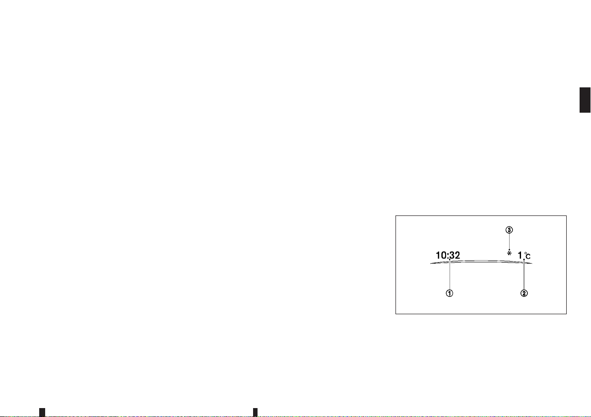
11. “4x4-i” display (where fitted)
When the [4x4-i] display is selected, you can view
the distribution ratio of the transmission torque to
the front and rear wheels during driving.
12. Chassis control
When Active Trace Control, Active Engine Brake or
Active Ride Control system is operated, it shows
the operating condition. It alsoshows operatingcondition of Hill Start Assist or the Hill Descent Control.
For more details, see “Active Trace Control” in the
“5. Starting and driving” section, “Active Engine
Brake (Xtronic Continuously Variable Transmission
(CVT) model)” in the “5. Starting and driving” section, “Active Ride Control” in the “5. Starting and
driving” section, “Hill Start Assist system” in the
“5. Starting and driving” section and “Hill descent
control system (where fitted)” in the “5. Starting and
driving” section.
13. Tyre Pressures (where fitted)
The tyre pressure mode shows the pressure of all
four tyres while the vehicle is driven.
When the Low Tyre Pressure warning appears, the
display can be switched to the tyre pressure mode
by pushing the <ENTER> button
tional details on the displayed warning.
j1 to reveal addi-
14. Driver Attention Alert system
(where fitted)
When the [Driver Attention] alert display is selected,
you can view your attention level as detected by the
system.
For more details, see “Driver Attention Alert (where
fitted)” later in this section.
15. Stop/Start System (where fitted)
The Stop/Start System mode shows the CO2 or
fuel savings and the engine stop time.
For more details, see “Stop/Start System (where
fitted)” in the “5. Starting and driving” section.
Trip CO2 or fuel saving and engine stop time:
The trip CO2 or fuel saving and engine stop time
mode shows amount of CO2 or fuel saved and the
engine stop time since the last reset.
The CO2 or fuel saving and engine stop time can be
reset by pushing the <ENTER> switch
Stop/Start menu.
For more details, see “Display Settings” earlier in
this section.
Total CO2 or fuel saving and engine stop time:
The total CO2 or fuel saving and engine stop time
mode shows:
The estimated CO2 exhaust emissions
•
prevented.
The timethat the engine has been stopped forby
•
the Stop/Start System.
j1 in the
NOTE
The Total CO2 or fuel saving and engine stop
time values cannot be reset and show accumulated Stop/Start System information since the
vehicle was built.
16. Traffic Sign Recognition
(where fitted)
The TrafficSign Recognition (TSR) system provides
the driver with information about the most recently
detected speed limit.
For more details, see “Traffic Sign Recognition
(TSR) (where fitted)” later in this section.
CLOCK AND OUTSIDE AIR
TEMPERATURE
JVI0932XZ
The clock j1 and outside air temperature j2 are
displayed on the upper side of the vehicle information display.
Instruments and controls 2-31
Page 94
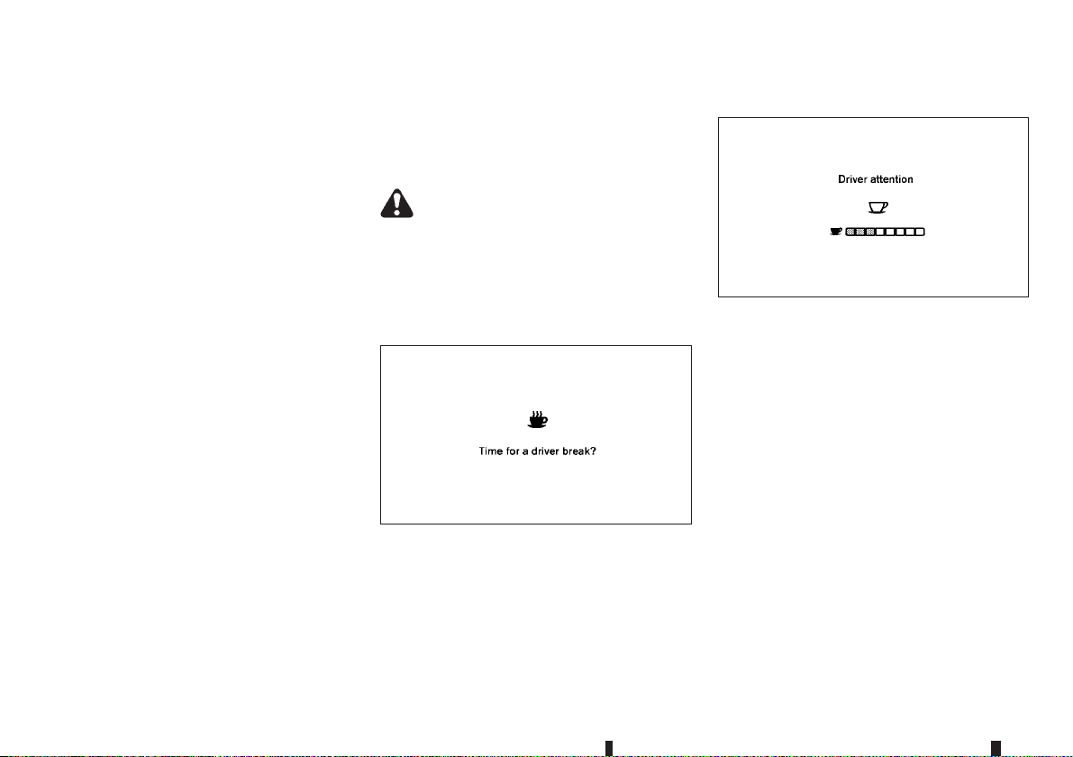
Clock
For clock adjustment, see “Clock” earlier in this
section, “Vehicle information and settings (models
with navigation system)” in the “4. Display screen,
heater and air conditioner, and audio system” section and “ SETUP button” in the “4. Display screen,
heater and air conditioner, and audio system” section.
Outside air temperature (°C or °F)
The outside air temperature is displayed in °C or °F
in the range of −40 to 60°C (−40 to 140°F).
The outside air temperature mode includes a low
temperature warning feature. If the outside air temperature is below 3°C (37°F), the warning
played on the screen (where fitted).
The outside temperature sensor islocated in front of
the radiator. The sensor may be affected by road or
engine heat, wind directions and other driving conditions. The display may differ from the actual outside temperature or the temperature displayed on
various signs or billboards.
j3 is dis-
DRIVER ATTENTION ALERT
(where fitted)
The [Driver Attention] option can be used to activate
or deactivate the Driver Attention Support feature.
This system is able to detect whether the driver is
displaying a lack of attention, or is distracted.
It does this by monitoring driving style, and steering
behaviour, and it notes deviations from the normal
pattern. If the system detects that driver attention is
decreasing, the system uses an audible and visual
warning to suggest that the driver take a break.
WARNING
This system is not designed to assist driving impaired due to fatigue, or other causes. Be attentive at all times, and avoid driving when tired.
Failure to do so could cause you to lose control
of the vehicle, resulting in a serious accident.
System operation
JVI0991XZ
If thesystem detects that driverattention is decreasing, the message [Time for a driver break?] appears
in the vehicle information display and a buzzer
sounds when the vehicle is driven at speeds above
60 km/h (37 MPH).
Attention level indicator:
JVI0992XZ
When the [Driver Attention] display is selected, you
can view your attention level as detected by the system.
For more details, see “Settings” earlier in this section.
NOTE
The attention level indicator consists of eight
•
levels.
When stopping the engine, the system is re-
•
set.
Turning the Driver Attention Alert system
on and off
To activate ordeactivate thisfunction, see “Settings”
earlier in this section.
NOTE
The setting will be retained even if the engine is
restarted.
2-32 Instruments and controls
Page 95
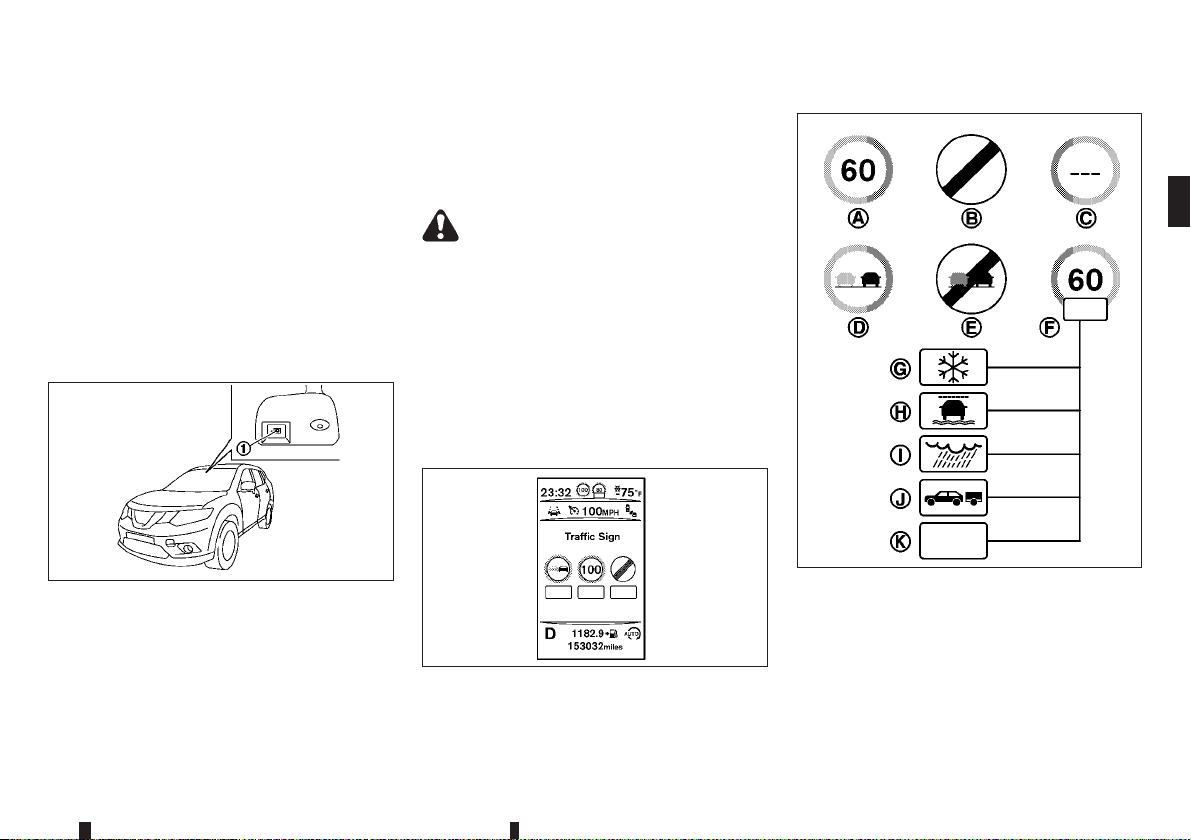
System Malfunction
If the Driver Attention Alert system malfunctions, the
system warning message will appear in the vehicle
information display and the function will be stopped
automatically.
Action to take:
Stop the vehicle in a safe location, and then turn off
and restart the engine. If the system warning message continues to appear, have the system checked
by a NISSAN dealer or qualified workshop.
TRAFFIC SIGN RECOGNITION (TSR)
(where fitted)
displayed is based on a combination of navigation
system data and live camera recognition. TSR information is always displayed at the top of the vehicle
information display, and optionally in the main central area of the display screen.
WARNING
The TSR system is only intended to be a support
device to provide the driver with information. It is
not a replacement for the driver’s attention to
traffic conditions or responsibility to drive safely.
It cannot prevent accidents due to carelessness.
It is the driver’s responsibility to stay alert and
drive safely at all times.
System operation
The traffic recognition system displays the following
types of road sign:
JVI0975XZ
The TrafficSign Recognition (TSR) system provides
the driver with information about the most recently
detected speed limit. The system captures the road
sign information with the multi-sensing front camera
unit
j1 located on the windscreen in front of the
inside rearview mirror and displays the detected
signs in the vehicle information display. For vehicles
equipped with navigation system, the speed limit
JVI1004XZ
Latest detected speed limit.
jA
National speed limit
jB
No speed limit information.
jC
No-overtaking zone.
jD
End of no-overtaking zone.
jE
Instruments and controls 2-33
JVI0973X
Page 96

Conditional speed limit, with the following
jF
available conditions:
Snow
jG
Slip (rain 1)
jH
Rain (rain 2)
jI
Towing
jJ
Generic
jK
CAUTION
The Traffic Sign Recognition (TSR) system is
•
intended as an aid to careful driving. It is the
driver’s responsibility to stay alert, drive
safely, and observe all road regulations that
currently apply, including looking out for road
signs.
The Traffic Sign Recognition (TSR) system
•
may not function properly under the following
conditions:
– When rain, snow or dirt adheres to the
windscreen in front of the TSR cameraunit.
– When the headlights are not bright due to
dirt on the lens or if the aiming is not adjusted properly.
– When strong light enters the camera unit.
(For example, the light directly shines on
the front of the vehicle at sunrise or sunset.)
– When a sudden change in brightness oc-
curs. (For example, when the vehicle enters or exits a tunnel or under a bridge.)
– In areas not covered by the navigation sys-
tem.
– If there are deviations in relation to the
navigation, for example due to changes in
the road routing.
– When overtaking buses or trucks with
speed stickers.
Turning the TSR system on and off
Turning the TSR system on or off is done using the
[Settings] menu in the vehicle information display.
For details, see “Vehicle information display” earlier
in this section.
Perform the following steps to enable or disable the
TSR system:
1. In the [Settings] menu, select the [Driver Assistance] key.
2. Touch [Traffic Sign] to turn the system ON/OFF.
System temporarily unavailable
If the vehicle is parked in direct sunlight under high
temperature conditions (over approximately 40°C
(104°F) and then started, the TSR system may be
deactivated automatically. The [Not available High
cabin temperature] warning message will appear in
the vehicle information display.
Action to take:
When the interior temperature is reduced, the TSR
system will resume operating automatically.
System Malfunction
If the TSR system malfunctions it will be turned off
automatically and the system [Malfunction]/[System
fault] warning message will appear in the vehicle
information display.
Action to take:
If the TSR [Malfunction]/[System fault]message appears, pull off the road at a safe location and stop
the vehicle. Turn the engine off and restart the engine. If the TSR [Malfunction]/[System fault] message continues to appear, have the system checked
by a NISSAN dealer or qualified workshop.
Maintenance
The TSR uses the same multi-sensing front camera
unit that is used by the Lane Departure Warning
(LDW) system, locatedin frontof theinside rearview
mirror. For maintenance of the camera, see “Camera unitmaintenance” in the “5. Startingand driving”
section.
2-34 Instruments and controls
Page 97
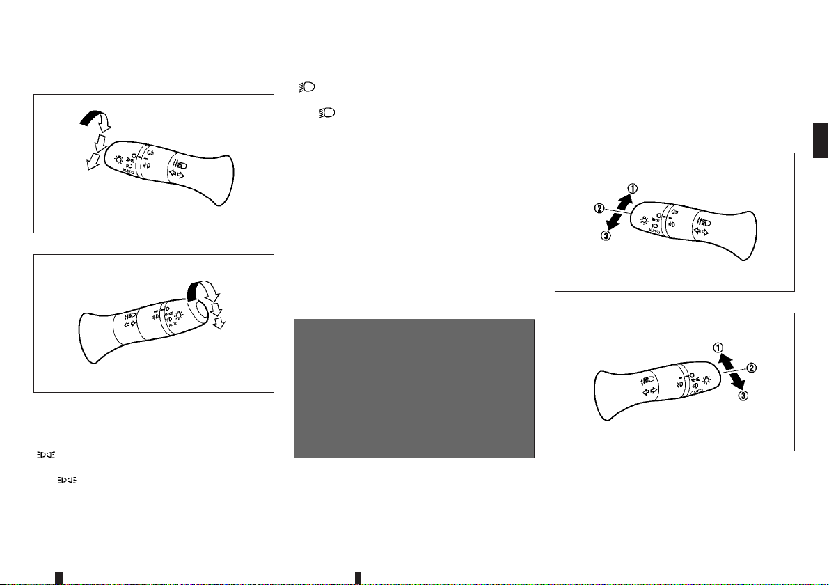
HEADLIGHT AND TURN SIGNAL
SWITCH
HEADLIGHT SWITCH
Type A
Type B
NISSAN recommends that you consult the local
regulations concerning the use of lights.
m
position
The position turns on the front clearance, tail,
number plate and instrument panel lights.
JVI0854XZ
JVI0859XZ
m
position
The position turns on the headlights in addition
to the other lights.
AUTO position (where fitted)
When the ignition switch is in the ON position and
the headlight switch is in the AUTO position, the
headlights, front clearance lights, instrument panel
lights, rear combination lights and other lights turn
on automatically depending on the brightness of the
surroundings.
The headlights will turn on automatically at twilight
or in rainy weather (when the windscreen wiper is
operated continuously).
When the ignition switch is placed in the LOCK or
OFF position, the lights will turn off automatically.
JVI0510XZ
CAUTION
Do not place any objects on top of the sensor
jA.
The sensor senses the brightness level and controls the autolight function. If the sensor is covered, it reacts as if it is dark, and the headlights
will illuminate.
Headlight beam
Type A
Type B
To turn on the high beam, push the lever towards
the front position
To turn off the high beam, return the lever to the
neutral position
j1.
j2.
JVI0856XZ
JVI0994XZ
Instruments and controls 2-35
Page 98

To flash the headlights, pull the lever towards the
rearmost position
even when the headlights are not on.
Where fitted, when the lever is pulled towards the
rearmost position
placed to the OFF or LOCK position, the headlight
will turn on and stay on for 30 seconds. The lever
can be pulled 4 times for up to 2 minutes.
j3 . The headlights can be flashed
j3 after the ignition switch is
High beam assist (where fitted)
The high beam assist system will operate when the
vehicle is driven at speeds of approximately 40 km/h
(25 MPH) and above. If an oncoming vehicle or
leading vehicleappears in front of your vehicle when
the headlight high beam is on, the headlight will be
switched to the low beam automatically.
Precautions on high beam assist:
WARNING
The high beamassist systemis aconvenience
•
but it is not a substitute for safe driving operation. The driver should remain alert at all
times, ensure safe driving practices and
switch the high beam and low beam manually
when necessary.
The high beam or low beam may not switch
•
automatically under the following conditions.
Switch the high beam and low beam manually.
– During bad weather (rain, fog, snow, wind,
etc.).
– When a light source similar to a headlight
or tail light is in the vicinity of the vehicle.
– When the headlights of the oncoming ve-
hicle or the leading vehicle are turned off,
when the colour of thelight is affected due
to foreign materials on the lights, or when
the light beam is out of position.
– When there is a sudden, continuous
change in brightness.
– When driving on a road that passes over
rolling hills, or a road that has level differ-
ences.
– When driving on a road with many curves.
– When a sign or mirror-like surface is re-
flecting intense light towards the front of
the vehicle.
– When the container, etc. being towed by a
leading vehicle is reflecting intense light.
– When a headlight on your vehicle is dam-
aged or dirty.
– When the vehicle is leaning at an angle
due to a punctured tyre, being towed, etc.
The timing of switching the low beamand high
•
beam may change under the following situations.
– The brightness of the headlights of the on-
coming vehicle or leading vehicle.
– The movement anddirection ofthe oncom-
ing vehicle and the leading vehicle.
– When only one light on the oncoming ve-
hicle or the leading vehicle is illuminated.
– When the oncoming vehicle or the leading
vehicle is a two-wheeled vehicle.
– Road conditions (incline, curve, the road
surface, etc.).
– The number ofpassengers andthe amount
of luggage.
2-36 Instruments and controls
Page 99
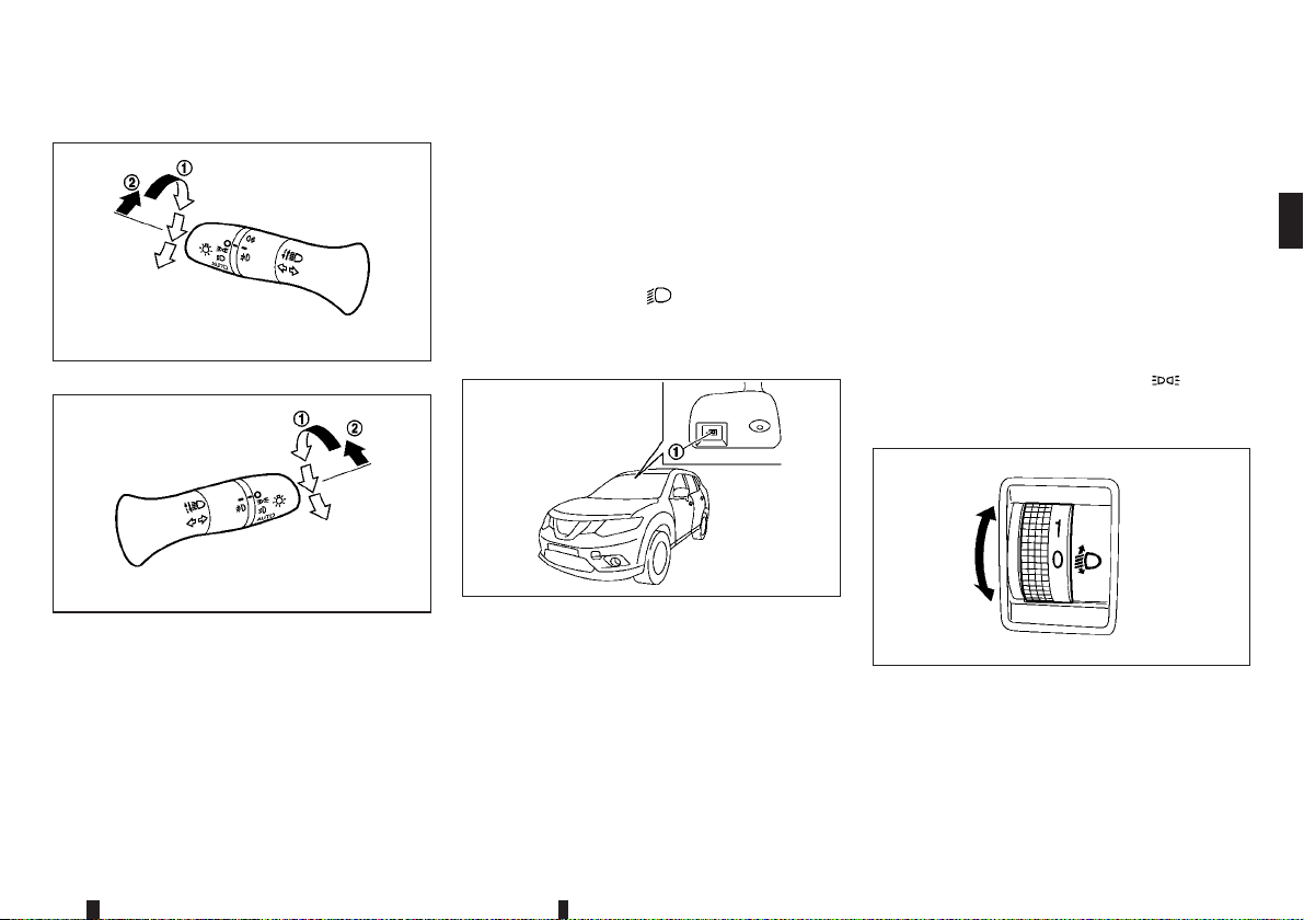
High beam assist operations:
Type A
JVI0974XZ
the system is not functioning properly. Have the system checked by a NISSAN dealer or qualified workshop.
When the vehicle speed lowersto less thanapproximately 25km/h (16 MPH), the headlight remains the
low beam.
To turn off the high beam assist system, turn the
headlight switch to the
low beam position by placing the lever in the neutral
position.
Ambient image sensor maintenance:
position or select the
Do not strike or damage the areas around the
•
ambient image sensor. Do not touch the sensor
lens that is located onthe ambient imagesensor.
If the ambient image sensor is damaged due to an
accident, contact a NISSAN dealer or qualified
workshop.
Daytime running light system
Even if the headlight switch is C position, the daytime running lights will come on after starting the
engine.
When the light switch is turned to the
the daytime running light will turn off.
position,
HEADLIGHT AIMING CONTROL
Type B
To activate the high beam assist system, turn the
headlight switch to the AUTO position
the lever forward
beam assist indicator light in the meter willilluminate
while the headlights are turned on.
If the high beam assist indicator light does not illuminate in the above condition, it may indicate that
j2 (high beam position). The high
JVI0996XZ
j1 and push
JVI0975XZ
The ambient image sensor
assist system is located infront ofthe inside rearview
mirror. To keep the proper operation of the high
beam assist system and prevent a system malfunction, be sure to observe the following:
Always keep the windscreen clean.
•
Do not attach a sticker (including transparent
•
material) orinstall an accessory near the ambient
image sensor.
j1 for the high beam
JVI0477XZ
Manual type
The headlight aiming control operates when the ignition switch is in the ON position and the headlight
is on to allow the headlight axis to be adjusted according to the driving condition.
Instruments and controls 2-37
Page 100

When driving with no heavy load/luggage or driving
on a flat road, select the normal position 0.
If the number of occupants and load/luggage in the
vehicle changes, the headlight axis may become
higher than normal.
If the vehicle is travelling on a hilly road, the headlights may directly shine on the rearview and outside
mirrors of a vehicle ahead or the windscreen of an
oncoming vehicle,which may obscure other drivers’
vision.
To adjust tothe properaiming height,turn theswitch
accordingly. The higher the number, designated on
the switch, the lower the headlight axis.
2-38 Instruments and controls
 Loading...