

Page 1

STARTING & CHARGING SYSTEM
GI
MA
CONTENTS
PRECAUTIONS ...............................................................2
Supplemental Restraint System (SRS) ″AIR
BAG″ and ″SEAT BELT PRE-TENSIONER″...............2
Wiring Diagrams and Trouble Diagnosis.....................2
PREPARATION ...............................................................3
Special Service Tool ....................................................3
BATTERY.........................................................................4
How to Handle Battery ................................................4
METHODS OF PREVENTING OVER-DISCHARGE
CHECKING ELECTROLYTE LEVEL
SPECIFIC GRAVITY CHECK
CHARGING THE BATTERY
Trouble Diagnoses with Battery/Starting/Charging
System Tester ..............................................................7
DIAGNOSTIC RESULT ITEM CHART
STARTING SYSTEM.....................................................10
System Description....................................................10
M/T MODELS
A/T MODELS
Wiring Diagram - START -.........................................11
M/T MODELS
A/T MODELS
Trouble Diagnoses with Battery/Starting/Charging
System Tester ............................................................13
DIAGNOSTIC RESULT ITEM CHART
WORK FLOW
DIAGNOSTIC PROCEDURE 1
DIAGNOSTIC PROCEDURE 2
..........................................................10
...........................................................10
..........................................................11
...........................................................12
..........................................................15
........................................6
............................4
......................................5
..........................9
........................14
..................................16
..................................18
......4
SECTION
MINIMUM SPECIFICATION OF CRANKING
VOLTAGE REFERENCING COOLANT
TEMPERATURE
Construction...............................................................19
Removal and Installation...........................................20
REMOVAL
INSTALLATION
Pinion/Clutch Check ..................................................21
CHARGING SYSTEM....................................................22
System Description....................................................22
Wiring Diagram - CHARGE -.....................................23
Trouble Diagnoses with Battery/Starting/Charging
System Tester ............................................................24
DIAGNOSTIC RESULT ITEM CHART
WORK FLOW
DIAGNOSTIC PROCEDURE 1
DIAGNOSTIC PROCEDURE 2
DIAGNOSTIC PROCEDURE 3
MALFUNCTION INDICATOR
Construction...............................................................31
Removal and Installation...........................................31
REMOVAL
INSTALLATION
SERVICE DATA AND SPECIFICATIONS (SDS).........32
Battery........................................................................32
Starter........................................................................32
Alternator ...................................................................32
......................................................19
...............................................................20
........................................................20
..........................................................27
...............................................................31
........................................................31
SC
........................26
..................................28
..................................29
..................................30
....................................30
EM
LC
EC
FE
CL
MT
AT
AX
SU
BR
ST
RS
BT
HA
EL
IDX
Page 2

PRECAUTIONS
Supplemental Restraint System (SRS) “AIR BAG” and “SEAT BELT PRE-TENSIONER”
Supplemental Restraint System (SRS) “AIR
BAG” and “SEAT BELT PRE-TENSIONER”
The Supplemental Restraint System such as “AIR BAG” and “SEAT BELTPRE-TENSIONER” used along with
a seat belt, helps to reduce the risk or severity of injury to the driver and front passenger for certain types of
collision. This system includes seat belt switch inputs and dual stage front air bag modules. The SRS system
uses the seat belt switches to determine the front air bag deployment, and may only deploy one front air bag,
depending on the severity of a collision and whether the front occupants are belted or unbelted. The SRS
system composition which is available to NISSAN MODELA33 is as follows:
I For a frontal collision
The Supplemental Restraint System consists of driver air bag module (located in the center of the steering wheel), front passenger air bag module (located on the instrument panel on passenger side), seat belt
pre-tensioners, a diagnosis sensor unit, crash zone sensor, warning lamp, wiring harness and spiral cable.
I For a side collision
The Supplemental Restraint System consists of front side air bag module (located in the outer side of front
seat), satellite sensor, diagnosis sensor unit (one of components of air bags for a frontal collision), wiring
harness, warning lamp (one of components of air bags for a frontal collision).
Information necessary to service the system safely is included in the RS section of this Service Manual.
WARNING:
I To avoid rendering the SRS inoperative, which could increase the risk of personal injury or death
in the event of a collision which would result in air bag inflation, all maintenance should be performed by an authorized NISSAN dealer.
I Improper maintenance, including incorrect removal and installation of the SRS, can lead to per-
sonal injury caused by unintentional activation of the system. For removal of Spiral Cable and Air
Bag Module, see the RS section.
I Do not use electrical test equipment on any circuit related to the SRS unless instructed to in this
Service Manual. SRS wiring harnesses can be identified by yellow and/or orange harness connector.
NFSC0001
Wiring Diagrams and Trouble Diagnosis
When you read wiring diagrams, refer to the following:
I GI-9, “HOW TO READ WIRING DIAGRAMS”
I EL-11, “POWER SUPPLY ROUTING” for power distribution circuit
When you perform trouble diagnosis, refer to the following:
I GI-35, “HOW TO FOLLOW TEST GROUPS IN TROUBLE DIAGNOSES”
I GI-24, “HOW TO PERFORM EFFICIENT DIAGNOSES FOR AN ELECTRICAL INCIDENT”
NFSC0002
SC-2
Page 3
PREPARATION
Special Service Tool
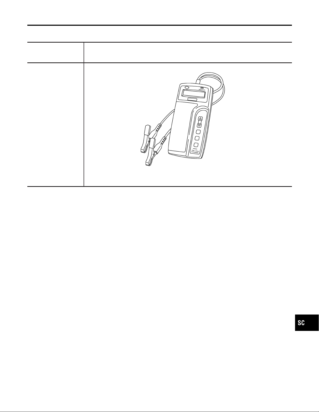
Special Service Tool
The actual shapes of Kent-Moore tools may differ from those of special service tools illustrated here.
Tool number
(Kent-Moore No.)
Tool name
—
(J-44373 Model 620)
Battery/Starting/Charging
system tester
Description
SEL403X
NFSC0017
GI
MA
EM
LC
EC
FE
CL
MT
AT
AX
SU
BR
ST
RS
BT
HA
EL
SC-3
IDX
Page 4
How to Handle Battery
BATTERY
MEL040F
How to Handle Battery
NFSC0003
CAUTION:
I If it becomes necessary to start the engine with a booster
battery and jumper cables, use a 12-volt booster battery.
I After connecting battery cables, ensure that they are
tightly clamped to battery terminals for good contact.
METHODS OF PREVENTING OVER-DISCHARGE
NFSC0003S01
The following precautions must be taken to prevent over-discharging a battery.
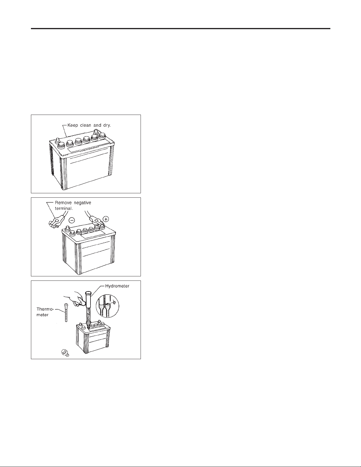
I The battery surface (particularly its top) should always be kept
clean and dry.
I The terminal connections should be clean and tight.
I At every routine maintenance, check the electrolyte level.
This also applies to batteries designated as “low maintenance”
and “maintenance-free”.
I When the vehicle is not going to be used over a long period of
time, disconnect the negative battery terminal. (If the vehicle
has an extended storage switch, turn it off.)
MEL041F
MEL042F
I Check the charge condition of the battery.
Periodically check the specific gravity of the electrolyte. Keep
a close check on charge condition to prevent over-discharge.
CHECKING ELECTROLYTE LEVEL
NFSC0003S02
WARNING:
Do not allow battery fluid to come in contact with skin, eyes,
fabrics, or painted surfaces. After touching a battery, do not
touch or rub your eyes until you have thoroughly washed your
hands. If acid contacts eyes, skin or clothing, immediately
flush with water for 15 minutes and seek medical attention.
SC-4
Page 5
BATTERY
How to Handle Battery (Cont’d)
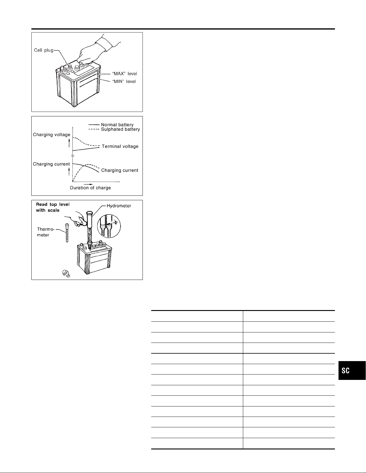
I Remove the cell plug using a suitable tool.
I Add distilled water up to the MAX level.
GI
MA
EM
MEL043F
SEL709EA
MEL042FA
Sulphation
A battery will be completely discharged if it is left unattended
for a long time and the specific gravity will become less than
1.100. This may result in sulphation on the cell plates.
To determine if a battery has been “sulphated”, note its voltage and current when charging it. As shown in the figure, less
current and higher voltage are observed in the initial stage of
charging sulphated batteries.
A sulphated battery may sometimes be brought back into service by means of a long, slow charge, 12 hours or more, followed by a battery capacity test.
SPECIFIC GRAVITY CHECK
1. Read hydrometer and thermometer indications at eye level.
2. Use the chart below to correct your hydrometer reading
according to electrolyte temperature.
NFSC0003S0201
NFSC0003S03
LC
EC
FE
CL
MT
AT
AX
SU
BR
ST
Hydrometer Temperature Correction
Battery electrolyte temperature °C (°F) Add to specific gravity reading
71 (160) 0.032
66 (150) 0.028
60 (140) 0.024
54 (130) 0.020
49 (120) 0.016
43 (110) 0.012
38 (100) 0.008
32 (90) 0.004
27 (80) 0
21 (70) −0.004
16 (60) −0.008
10 (50) −0.012
NFSC0003S0301
SC-5
RS
BT
HA
EL
IDX
Page 6

How to Handle Battery (Cont’d)
BATTERY
Battery electrolyte temperature °C (°F) Add to specific gravity reading
4 (40) −0.016
−1 (30) −0.020
−7 (20) −0.024
−12 (10) −0.028
−18 (0) −0.032
Corrected specific gravity Approximate charge condition
1.260 - 1.280 Fully charged
1.230 - 1.250 3/4 charged
1.200 - 1.220 1/2 charged
1.170 - 1.190 1/4 charged
1.140 - 1.160 Almost discharged
1.110 - 1.130 Completely discharged
CHARGING THE BATTERY
NFSC0003S04
CAUTION:
I Do not “quick charge” a fully discharged battery.
I Keep the battery away from open flame while it is being
charged.
I When connecting the charger,connect the leads first, then
turn on the charger. Do not turn on the charger first, as
this may cause a spark.
I If battery electrolyte temperature rises above 55°C (131°F),
stop charging. Always charge battery at a temperature
below 55°C (131°F).
Charging Rates
Amps Time
50 1 hour
25 2 hours
10 5 hours
5 10 hours
NFSC0003S0401
Do not charge at more than 50 ampere rate.
NOTE:
The ammeter reading on your battery charger will automatically
decrease as the battery charges. This indicates that the voltage of
the battery is increasing normally as the state of charge improves.
The charging amps indicated above refer to initial charge rate.
I If, after charging, the specific gravity of any two cells varies
more than .050, the battery should be replaced.
SC-6
Page 7
BATTERY
Trouble Diagnoses with Battery/Starting/Charging System Tester
Trouble Diagnoses with
Battery/Starting/Charging System Tester
CAUTION:
When working with batteries, always wear appropriate eye
protection.
NOTE:
I To ensure a complete and thorough diagnosis, the battery,
starter and alternator test segments must be done as a set
from start to finish.
I If battery surface charge is detected while testing, the tester
will prompt you to turn on the headlights to remove the surface
charge.
I If necessary, the tester will prompt you to determine if the bat-
tery temperature is above or below 0°C (32°F). Choose the
appropriate selection by pressing the up or down arrow button,
then press “ENTER” to make the selection.
NFSC0018
GI
MA
EM
LC
EC
FE
CL
SEL404X
1. Turn off all loads on the vehicle electrical system. Clean or
repair as necessary.
2. Visually inspect the battery, battery terminals and cable ends
with ignition switch in “OFF” position.
NOTE:
The contact surface between the battery terminals, cable ends and
tester leads must be clean for a valid test. A poor connection will
prevent testing and a “CHECK CONNECTION” message will
appear during the test procedures. If this occurs, clean the battery
post and terminals, reconnect them and restart the test.
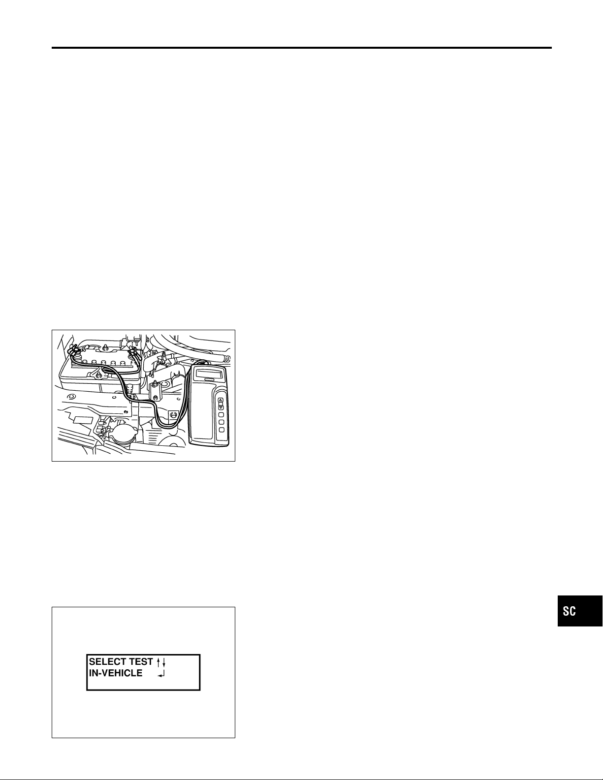
3. Connect the red tester lead clamp to the positive battery
terminal, and the black to the negative terminal.
MT
AT
AX
SU
BR
ST
RS
BT
HA
SEL405X
4. The tester will turn on automatically. Using the arrow keys,
select “IN VEHICLE” on the tester and then pressthe “ENTER”
key.
EL
IDX
SC-7
Page 8
BATTERY
Trouble Diagnoses with Battery/Starting/Charging System Tester (Cont’d)
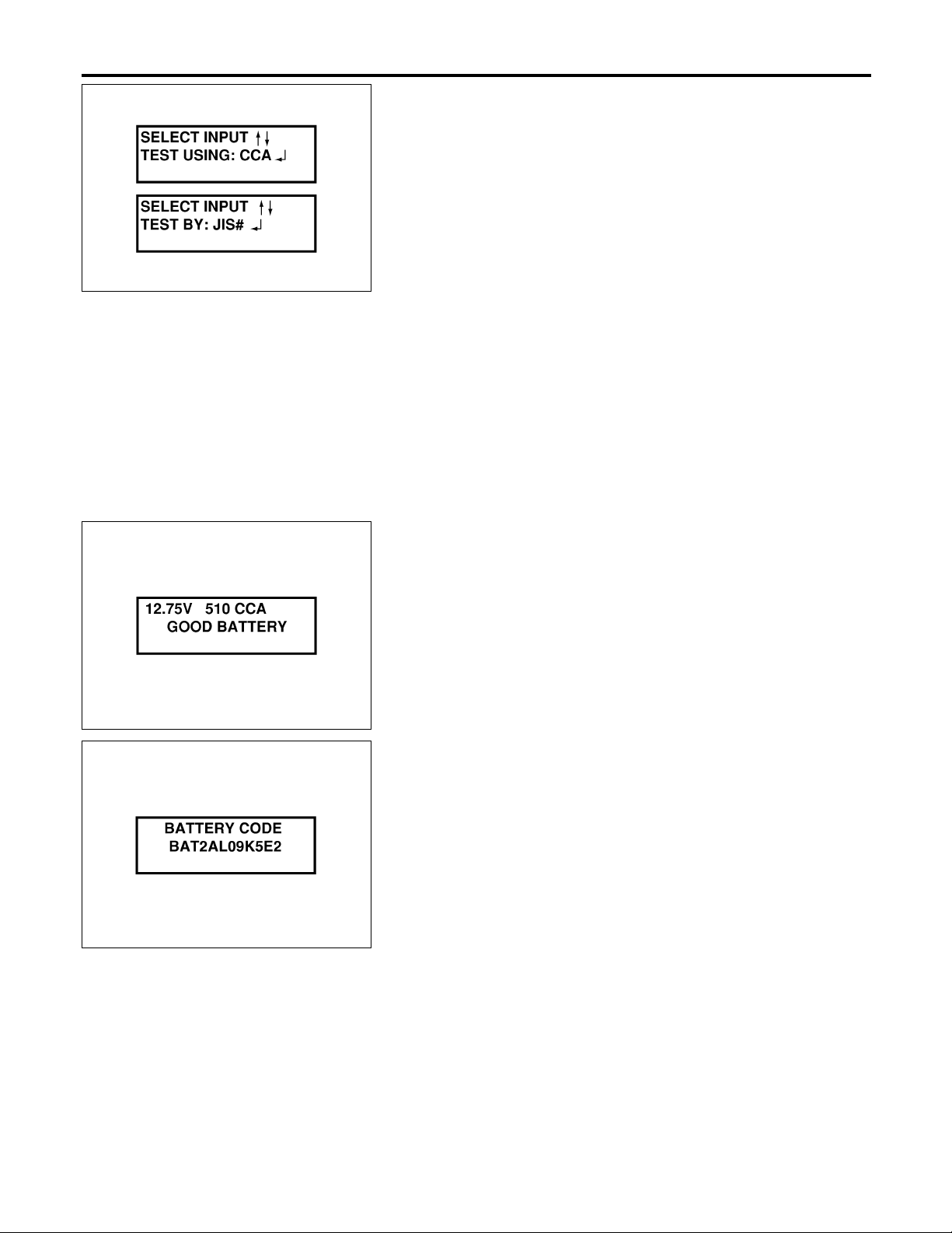
5. Locate the battery type and rating stamped or written on the
top case of the battery to be tested.
NOTE:
The battery type and rating will have either of the following.
CCA: Cold Cranking Amps (490 CCA, 550 CCA, etc.)
JIS: Japanese Industrial Standard.
Battery is stamped with a number such as:
80D26L: 80 (rank of output), D (physical size-depth), 26 (width
in cm). The last character L(post configuration) is not input into
the tester.
SEL406X
The tester requires the rating for the battery be entered exactly
as it is written or stamped on the battery.Do not attempt a CCA
conversion for JIS stamped batteries. JIS must be input
directly.
6. Using the arrow and “ENTER” keys alternately, select the battery type and rating.
NOTE:
The tester lists five choices; CCA, JIS, IEC, DIN, and EN. Only use
CCA or JIS.
SEL407X
SEL576X
7. Press “ENTER” to begin the test. Diagnosis results are displayed on the tester. Refer to “DIAGNOSTIC RESULT ITEM
CHART”, SC-9.
8. Press “ENTER”, then test output code is displayed. Record the
test output code on the repair order.
9. Toggle back to the “DIAGNOSTIC SCREEN” for test results.
NOTE:
I If necessary, the tester will ask the user to determine if the
battery has just been charged. Choose the appropriate selection by pressing the up or down arrow button and then press
the “ENTER” button to make the selection.
I When testing a battery installed in a vehicle that has recently
been driven, select “BEFORE CHANGE”.
I If the battery has just been slow charged due to a “CHARGE
& RETEST” decision by the tester, and the tester asks the user
“BEFORE CHARGE/AFTER CHARGE”, select “AFTER
CHARGE”.
SC-8
Page 9

BATTERY
Trouble Diagnoses with Battery/Starting/Charging System Tester (Cont’d)
DIAGNOSTIC RESULT ITEM CHART
Diagnostic item Service procedure
GOOD BATTERY Battery is OK, go to “Trouble Diagnoses”, “STARTING SYSTEM”. Refer to SC-13.
Replace battery.
REPLACE BATTERY
BAD CELL-REPLACE
GOOD-RECHARGE
CHARGE & RETEST
Before replacing battery, clean the battery cable clamps and battery posts. Perform battery test again with Battery/Starting/Charging system tester. If second test result is
“Replace Battery”, then do so. Perform battery test again to confirm repair.
Replace the battery. Perform battery test again with Battery/Starting/Charging system
tester to confirm repair.
Perform the slow battery charging procedure. (Initial rate of charge is 10A for 12 hours.)
Perform battery test again with Battery/Starting/Charging system tester.
Perform the slow battery charging. (Initial rate of charge is 10A for 12 hours.)
Perform battery test again with Battery/Starting/Charging system tester to confirm repair.
NOTE:
If the tester asks the user “BEFORE CHARGE/AFTER CHARGE”, select “AFTER
CHARGE”.
NFSC0018S01
GI
MA
EM
LC
EC
FE
CL
MT
AT
AX
SU
BR
ST
RS
BT
HA
SC-9
EL
IDX
Page 10

System Description
STARTING SYSTEM
System Description
M/T MODELS
NFSC0021
NFSC0021S01
Power is supplied at all times
I through 40A fusible link (letter C, located in the fuse and fusible link box)
I to ignition switch terminal 1.
With the ignition switch in the START position, power is supplied
I through terminal 5 of the ignition switch
I to clutch interlock relay terminal 5.
With the ignition switch in the ON or START position, power is supplied
I through 15A fuse [No. 20, located in the fuse block (J/B)]
I to clutch interlock relay terminal 1.
When the clutch pedal is depressed, ground is supplied to clutch interlock relay terminal 2 through the clutch
interlock switch and body grounds E11, E22 and E53.
The clutch interlock relay is energized and power is supplied
I from terminal 3 of the clutch interlock relay
I to terminal 2 of the starter motor windings.
The starter motor plunger closes and provides a closed circuit between the battery and the starter motor. The
starter motor is grounded to the cylinder block. With power and ground supplied, the starter motor operates.
A/T MODELS
NFSC0021S02
Power is supplied at all times
I through 40A fusible link (letter C, located in the fuse and fusible link box)
I to ignition switch terminal 1.
With the ignition switch in the ON or START position, power is supplied
I through 15A fuse [No. 20, located in the fuse block (J/B)]
I to park/neutral position relay terminal 1.
Also, with the ignition switch in the START position, power is supplied
I from ignition switch terminal 5
I to park/neutral position relay terminal 5.
Ground is supplied, with the selector lever in the P or N position
I to park/neutral position relay terminal 2
I through park/neutral position switch.
The park/neutral position relay is energized and power is supplied
I from ignition switch terminal 5
I through park/neutral position relay terminals 5 and 3
I to terminal 2 of the starter motor windings.
The starter motor plunger closes and provides a closed circuit between the battery and the starter motor. The
starter motor is grounded to the cylinder block. With power and ground supplied, the starter motor operates.
SC-10
Page 11

STARTING SYSTEM
Wiring Diagram — START —
M/T MODELS
Wiring Diagram — START —
NFSC0005
NFSC0005S03
GI
MA
EM
LC
EC
FE
CL
MT
AT
AX
SU
BR
ST
RS
BT
HA
SC-11
EL
IDX
MEL434R
Page 12

Wiring Diagram — START — (Cont’d)
STARTING SYSTEM
A/T MODELS
NFSC0005S04
SC-12
MEL835P
Page 13

STARTING SYSTEM
Trouble Diagnoses with Battery/Starting/Charging System Tester
Trouble Diagnoses with
Battery/Starting/Charging System Tester
NOTE:
To ensure a complete and thorough diagnosis, the battery, starter
and alternator test segments must be done as a set from start to
finish.
1. Turn off all loads on the vehicle electrical system.
2. Perform battery test with Battery/Starting/Charging system
tester. Refer to SC-7.
3. Press “ENTER” to begin the starting system test.
NFSC0019
GI
MA
EM
LC
EC
FE
CL
SEL408X
SEL409X
SEL410X
4. Start the engine.
5. Diagnosis result is displayed on the tester. Refer to “DIAGNOSTIC RESULT ITEM CHART”, SC-14.
NOTE:
I If the starter performs normally but the engine does not start,
perform engine diagnosis.
I For intermittent “NO CRANK” or “NO STARTER OPERATION”
incidents, go to DIAGNOSTIC PROCEDURE 2.
MT
AT
AX
SU
BR
ST
RS
BT
HA
SC-13
EL
IDX
Page 14

STARTING SYSTEM
Trouble Diagnoses with Battery/Starting/Charging System Tester (Cont’d)
DIAGNOSTIC RESULT ITEM CHART
Diagnostic item Service procedure
CRANKING VOLTAGE NORMAL Go to “WORK FLOW”, SC-15.
CRANKING VOLTAGE LOW Go to “WORK FLOW”, SC-15.
CHARGE BATTERY
REPLACE BATTERY
Perform the slow battery charging procedure. (Initial rate of charge is 10A for 12 hours.)
Perform battery test again with Battery/Starting/Charging system tester. Refer to SC-7.
Before replacing battery, clean the battery cable clamps and battery posts. Perform battery test again with Battery/Starting/Charging system tester. Refer to SC-7. If second test
result is “REPLACE BATTERY”, then do so. Perform battery test again to confirm repair.
NFSC0019S01
SC-14
Page 15

STARTING SYSTEM
Trouble Diagnoses with Battery/Starting/Charging System Tester (Cont’d)
WORK FLOW
NFSC0019S02
GI
MA
EM
LC
EC
FE
CL
MT
AT
AX
SU
BR
ST
RS
BT
HA
*1 SC-7
*2 SC-19
*3 SC-16 *4 SC-18
SC-15
SEL411X
EL
IDX
Page 16

STARTING SYSTEM
Trouble Diagnoses with Battery/Starting/Charging System Tester (Cont’d)
DIAGNOSTIC PROCEDURE 1
Check “B” Terminal Circuit
1 CHECK POWER SUPPLY FOR STARTER MOTOR “B” TERMINAL
1. Remove the fuel pump fuse.
2. Crank or start the engine (where possible) until the fuel pressure is released.
3. Turn the ignition OFF.
4. Check that the starter motor connector E202 terminal 1 (B/R) connection is clean and tight.
5. Check voltage between starter motor B terminal E202 terminal 1 (B/R) and ground using a digital circuit tester.
OK or NG
OK © GO TO 2.
NG © Check harness between the battery and the starter motor for open circuit.
NFSC0019S03
NFSC0019S0301
SEL961XA
2 CHECK BATTERY CABLE CONNECTION QUALITY (VOLTAGE DROP TEST)
1. Check voltage between starter motor B terminal E202 terminal 1 (B/R) and battery positive terminal using a digital cir-
cuit tester.
SEL962XA
OK or NG
OK © GO TO 3.
NG © Check harness between the battery and the starter motor for poor continuity.
SC-16
Page 17

STARTING SYSTEM
Trouble Diagnoses with Battery/Starting/Charging System Tester (Cont’d)
3 CHECK STARTER MOTOR GROUND CIRCUIT (VOLTAGE DROP TEST)
1. Check voltage between starter motor case and battery negative terminal using a digital circuit tester.
GI
MA
EM
LC
EC
FE
CL
SEL372Y
OK or NG
OK © Starter motor “B” terminal circuit is OK. Further inspection necessary. Refer to “WORK
FLOW”, SC-15.
NG © Check the starter motor case and ground for poor continuity.
MT
AT
AX
SU
BR
ST
RS
BT
HA
SC-17
EL
IDX
Page 18

STARTING SYSTEM
Trouble Diagnoses with Battery/Starting/Charging System Tester (Cont’d)
DIAGNOSTIC PROCEDURE 2
Check “S” Terminal Circuit
1 CHECK POWER SUPPLY FOR STARTER MOTOR “S” TERMINAL
1. Remove the fuel pump fuse.
2. Crank or start the engine (where possible) until the fuel pressure is released.
3. Turn the ignition OFF.
4. Disconnect starter motor connector.
5. Check voltage between starter motor connector E203 terminal 2 (B/R) (M/T models) or E201 terminal 2 (B/R) (A/T
models) and ground using a digital circuit tester.
OK or NG
OK © GO TO 2.
NG © Check the following.
I 40A fusible link (letter C, located in fuse and fusible link box)
I Park/neutral position relay
I Harness for open or short
NFSC0019S0401
=NFSC0019S04
SEL373Y
2 CHECK “S” TERMINAL CONNECTION QUALITY (VOLTAGE DROP TEST)
1. Connect starter motor connector.
2. Check voltage between starter motor connector E203 terminal 2 (B/R) (M/T models) or E201 terminal 2 (B/R) (A/T
models) and battery positive terminal using a digital circuit tester.
SEL973Y
OK or NG
OK © Starter motor “S” terminal circuit is OK. Further inspection necessary. Refer to “WORK
FLOW”, SC-15.
NG © Check harness between the battery and the starter motor “S” terminal for poor continuity.
SC-18
Page 19

STARTING SYSTEM
Trouble Diagnoses with Battery/Starting/Charging System Tester (Cont’d)
MINIMUM SPECIFICATION OF CRANKING VOLTAGE REFERENCING COOLANT TEMPERATURE
Engine coolant temperature Voltage V
=NFSC0019S05
GI
−30°C to −20°C (−22°F to −4°F) 8.2
−19°C to −10°C (−2°F to 14°F) 8.7
−9°C to 0°C (16°F to 32°F) 9.1
More than 1°C (More than 34°F) 9.4
Construction
MA
EM
LC
NFSC0006
EC
FE
CL
MT
AT
AX
MEL208O
SU
BR
ST
RS
BT
HA
EL
IDX
SC-19
Page 20

Construction (Cont’d)
STARTING SYSTEM
SEL457T
Removal and Installation
REMOVAL
1. Remove air duct assembly.
2. Remove harness protector from engine room harness.
3. Disconnect starter harness.
4. Remove starter bolts (two).
5. Remove starter.
INSTALLATION
To install, reverse the removal procedure.
MEL209O
NFSC0007
NFSC0007S01
NFSC0007S02
SEL458T
SC-20
Page 21

STARTING SYSTEM
Pinion/Clutch Check
Pinion/Clutch Check
1. Inspect pinion teeth.
I Replace pinion if teeth are worn or damaged. (Also check
condition of ring gear teeth.)
2. Inspect reduction gear teeth.
I Replace reduction gear if teeth are worn or damaged. (Also
check condition of armature shaft gear teeth.)
3. Check to see if pinion locks in one direction and rotates
smoothly in the opposite direction.
I If it locks or rotates in both directions, or unusual resistance is
evident, replace.
NFSC0008
GI
MA
EM
LC
EC
FE
CL
MT
AT
AX
SU
BR
ST
RS
BT
HA
SC-21
EL
IDX
Page 22

System Description
CHARGING SYSTEM
System Description
The alternator provides DC voltage to operate the vehicle’s electrical system and to keep the battery charged.
The voltage output is controlled by the IC regulator.
Power is supplied at all times to alternator terminal 3 (S) through:
I 120A fusible link (letter A, located in the fuse and fusible link box), and
I 10A fuse (No. 70, located in the fuse and fusible link box).
Terminal B supplies power to charge the battery and operate the vehicle’s electrical system. Output voltage
is controlled by the IC regulator at terminal 3 (S) detecting the input voltage. The charging circuit is protected
by the 120A fusible link.
The alternator is grounded to the engine block.
With the ignition switch in the ON or START position, power is supplied
I through 10A fuse [No. 30, located in the fuse block (J/B)]
I to combination meter terminal 24 for the charge warning lamp.
Ground is supplied to terminal 68 of the combination meter through terminal 2 (L) of the alternator. With power
and ground supplied, the charge warning lamp will illuminate. When the alternator is providing sufficient voltage with the engine running, the ground is opened and the charge warning lamp will go off.
If the charge warning lamp illuminates with the engine running, a fault is indicated.
NFSC0009
SC-22
Page 23

CHARGING SYSTEM
Wiring Diagram — CHARGE —
Wiring Diagram — CHARGE —
NFSC0010
GI
MA
EM
LC
EC
FE
CL
MT
AT
AX
SU
BR
ST
RS
BT
HA
SC-23
EL
IDX
MEL836P
Page 24

CHARGING SYSTEM
Trouble Diagnoses with Battery/Starting/Charging System Tester
Trouble Diagnoses with
Battery/Starting/Charging System Tester
NOTE:
To ensure a complete and thorough diagnosis, the battery, starter
and alternator test segments must be done as a set from start to
finish.
1. Turn off all loads on the vehicle electrical system.
2. Perform battery and starting system test with Battery/Starting/
Charging system tester.
3. Press “ENTER” to begin the charging system test.
4. Start engine.
NFSC0020
SEL417X
SEL418X
5. Press “ENTER” until “LOADS OFF REV ENGINE 5 SEC” is
displayed.
6. Raise and hold the engine speed at 1,500 to 2,000 rpm for
about 5 seconds, then return to the engine to idle.
Once the increase in engine rpm is detected, press “ENTER”
to continue.
NOTE:
I If after 30 seconds an increase in engine idle speed is not
detected, “RPM NOT DETECTED” will display.
I Some engines may have a higher idle initially after starting,
particularly when the engine is cold. The tester may detect this
without any other action being taken. If this occurs, continue on
with the testing process. The final results will not be affected.
SEL419X
7. The tester now checks the engine at idle and performs the
DIODE/RIPPLE check.
8. When complete, the tester will prompt you to turn on the following electrical loads.
I Heater fun set to highest. Do not run the A/C or windshield
defroster.
I Headlamp high beam
I Rear window defogger
NOTE:
Do not run the windshield wipers or any other cyclical loads.
SC-24
Page 25

CHARGING SYSTEM
Trouble Diagnoses with Battery/Starting/Charging System Tester (Cont’d)
9. Press “ENTER” to continue.
GI
MA
EM
SEL420X
SEL421X
SEL422X
10. Raise and hold the engine speed at 1,500 to 2,000 rpm for
about 5 seconds, then return the engine to idle. Once the
increase in engine rpm is detected, press “ENTER” to continue.
NOTE:
If after 30 seconds an increase in engine idle speed is not detected,
“RPM NOT DETECTED” will be displayed. Press “ENTER” to
restart the test.
11. Diagnostic result is displayed on the tester. Refer to “DIAGNOSTIC RESULT ITEM CHART”, SC-26.
12. Press “ENTER” then test output code is displayed. Record the
test output code on the repair order.
13. Toggle back to the “DIAGNOSTIC SCREEN” for test results.
LC
EC
FE
CL
MT
AT
AX
SU
BR
ST
RS
SEL577X
BT
HA
EL
IDX
SC-25
Page 26

CHARGING SYSTEM
Trouble Diagnoses with Battery/Starting/Charging System Tester (Cont’d)
DIAGNOSTIC RESULT ITEM CHART
Diagnostic item Service procedure
CHARGING SYSTEM NORMAL Charging system is normal and will also show DIODE RIPPLE test result.
NO CHARGING VOLTAGE Go to “WORK FLOW”, SC-27.
LOW CHARGING VOLTAGE Go to “WORK FLOW”, SC-27.
HIGH CHARGING VOLTAGE Go to “WORK FLOW”, SC-27.
DIODE RIPPLE NORMAL Diode ripple is OK and will also show CHARGING VOLTAGE test result.
EXCESS RIPPLE DETECTED
DIODE RIPPLE NOT DETECTED Go to “WORK FLOW”, SC-27.
Replace the alternator. Perform “DIODE RIPPLE” test again using Battery/Starting/
Charging system tester to confirm repair.
NFSC0020S01
SC-26
Page 27

CHARGING SYSTEM
Trouble Diagnoses with Battery/Starting/Charging System Tester (Cont’d)
WORK FLOW
NFSC0020S02
GI
MA
EM
LC
EC
FE
CL
MT
AT
AX
SU
BR
ST
RS
BT
HA
SC-27
EL
IDX
SEL423X
Page 28

CHARGING SYSTEM
Trouble Diagnoses with Battery/Starting/Charging System Tester (Cont’d)
DIAGNOSTIC PROCEDURE 1
Check “L” Terminal Circuit
NFSC0020S03
NFSC0020S0301
1 CHECK “L” TERMINAL CONNECTION
Check to see if “L” terminal is clean and tight.
OK or NG
OK © GO TO 2.
NG © Repair “L” terminal connection. Confirm repair by performing complete Battery/Starting/
Charging system test.
2 CHECK “L” TERMINAL CIRCUIT
1. Disconnect alternator connector.
2. Apply ground to alternator connector A2 terminal 2 (BR) with the ignition switch in the ON position.
SEL966X
OK or NG
OK © Replace the alternator. Confirm repair by performing complete Battery/Starting/Charging
system test.
NG © Check the following.
I 10A fuse [No. 30, located in fuse block (J/B)]
I CHARGE lamp
I Harness for open or short between combination meter and fuse
I Harness for open or short between combination meter and alternator
SC-28
Page 29

CHARGING SYSTEM
Trouble Diagnoses with Battery/Starting/Charging System Tester (Cont’d)
DIAGNOSTIC PROCEDURE 2
Check “B” Terminal Circuit
1 CHECK “B” TERMINAL CONNECTION
Check to see if “B” terminal is clean and tight.
OK or NG
OK © GO TO 2.
NG © Repair “B” terminal connection. Confirm repair by performing complete Battery/Starting/
Charging system test.
2 CHECK ALTERNATOR “B” TERMINAL CIRCUIT
Check voltage between alternator B terminal E46 terminal 1 (B/R) and ground using a digital circuit tester.
OK or NG
OK © GO TO 3.
NG © Check the following.
I 120A fusible link (letter A, located in fuse and fusible link box)
I Harness for open or short between alternator and fusible link
=NFSC0020S04
NFSC0020S0401
SEL967XA
GI
MA
EM
LC
EC
FE
CL
MT
AT
AX
SU
3 CHECK “B” TERMINAL CONNECTION QUALITY (VOLTAGE DROP TEST)
Check voltage between alternator B terminal E46 terminal 1 (B/R) and battery positive terminal using a digital circuit tester.
SEL968XA
OK or NG
OK © Replace the alternator. Confirm repair by performing complete Battery/Starting/Charging
system test.
NG © Check harness between the battery and the alternator for poor continuity.
BR
ST
RS
BT
HA
EL
IDX
SC-29
Page 30

CHARGING SYSTEM
Trouble Diagnoses with Battery/Starting/Charging System Tester (Cont’d)
DIAGNOSTIC PROCEDURE 3
Check “S” Terminal Circuit
=NFSC0020S05
NFSC0020S0501
1 CHECK “S” TERMINAL CONNECTION
Check to see if “S” terminal is clean and tight.
OK or NG
OK © GO TO 2.
NG © Repair “S” terminal connection. Confirm repair by performing complete Battery/Starting/
Charging system test.
2 CHECK ALTERNATOR “S” TERMINAL CIRCUIT
Check voltage between alternator connector A2 terminal 3 (B/R) and ground using a digital circuit tester.
SEL969X
OK or NG
OK © GO TO 3.
NG © Check the following.
I 10A fuse (No. 70, located in fuse and fusible link box)
I Harness for open or short between alternator and fuse
3 CHECK “S” TERMINAL CONNECTION QUALITY (VOLTAGE DROP TEST)
Check voltage between alternator connector A2 terminal 3 (B/R) and battery positive terminal using a digital circuit tester.
SEL970X
OK or NG
OK © Replace the alternator. Confirm repair by performing complete Battery/Starting/Charging
system test.
NG © Check harness between the battery and the alternator for poor continuity.
MALFUNCTION INDICATOR
NFSC0020S06
The IC regulator warning function activates to illuminate
“CHARGE” warning lamp, if any of the following symptoms occur
while alternator is operating:
I Excessive voltage is produced.
I No voltage is produced.
SC-30
Page 31

CHARGING SYSTEM
Construction
Construction
NFSC0012
GI
MA
EM
LC
EC
FE
CL
MT
SEL974Y
Removal and Installation
REMOVAL
1. Remove engine undercover RH.
2. Remove side inspection cover RH.
3. Remove radiator.
4. Loosen belt idler pulley.
5. Remove drive belt.
6. Disconnect alternator harness connector andA/C compressor
harness connector.
7. Remove alternator upper bolt and lower bolt.
INSTALLATION
To install, reverse the removal procedure.
NFSC0013
NFSC0013S01
NFSC0013S02
AT
AX
SU
BR
ST
RS
BT
HA
MEL384KA
EL
IDX
SC-31
Page 32

Battery
SERVICE DATA AND SPECIFICATIONS (SDS)
Battery
Type 80D26L
Capacity V-AH 12-55
Cold cranking current A
(For reference value)
582
Starter
M0T87281 M0T87181
Type
Applied model M/T A/T
System voltage 12V
Terminal voltage 11.0V
No-load
Minimum diameter of commutator 28.8 mm (1.134 in)
Minimum length of brush 7.0 mm (0.276 in)
Brush spring tension 18.3 - 24.8 N (1.87 - 2.53 kg, 4.12 - 5.58 lb)
Clearance between bearing metal and armature shaft Less than 0.2 mm (0.008 in)
Clearance between pinion front edge and pinion stopper 0.5 - 2.0 mm (0.020 - 0.079 in)
Current Less than 90A
Revolution More than 2,800 rpm
MITSUBISHI make
Reduction gear type
NFSC0014
NFSC0015
Alternator
Type
Nominal rating 12V-110A
Ground polarity Negative
Minimum revolution under no-load (When 13.5 volts is applied) Less than 1,100 rpm
Hot output current (When 13.5 volts is applied)
Regulated output voltage 14.1 - 14.7V
Minimum length of brush More than 6.00 mm (0.2362 in)
Brush spring pressure 1.000 - 3.432 N (102 - 350 g, 3.60 - 12.34 oz)
Slip ring minimum outer diameter More than 26.0 mm (1.024 in)
Rotor (Field coil) resistance 2.16 - 2.46Ω
LR1110-723V
HITACHI make
(More than 35A/1,300 rpm)
More than 70A/1,800 rpm
More than 91A/2,500 rpm
More than 110A/5,000 rpm
NFSC0016
SC-32
 Loading...