

Page 1

nissan :: Nissan-Datsun Maxima SE V6-2968cc
3.0L DOHC MFI (VQ30DE) (1997)
Page 2

> Relays and Modules > Relays and Modules - Accessories and Optional Equipment > Accessory Delay Module > Accessory Delay Relay > Component Information > Locations
Passenger Compartment
Page 3

Page 4

> Relays and Modules > Relays and Modules - Accessories and Optional Equipment > Alarm Module, (Vehicle Antitheft) > Component Information > Technical Service Bulletins > Customer Interest for Alarm Module: > 97-
040 > May > 97 > Keyless Entry - No Response to Remote
Alarm Module: Customer InterestKeyless Entry - No Response to Remote
Classification:EL97-004
reference:TB97-040
Date:May 28, 1997
1995-97 MAXIMA DOES NOT RESPOND TO REMOTE
APPLIED VEHICLE(S): 1995-97 Maxima (A32)
APPLIED VIN(S): Vehicles built before JN1CA21D*VT808742, JN1CA21 D*VT204048 and JN1CA21D*VM501530
APPLIED DATE(S): Vehicles built before August 1, 1996
SERVICE INFORMATIONThis bulletin provides information to address the concerns of any 1995,1996 or early 1997 Maxima owner who states their vehicle does not alwaysrespond to the remote switches. This incident is a cycle where a customer cites an inoperative remote switch, the dealer reprograms the remotes and theincident returns for no apparent reason.
Troubleshooting the remote control system per the service manual reveals not problems with the remote batteries, antenna, LCUO5, BCM or wireharness connections.
Such an incident may be caused by the owner jiggling the ignition key after locking the doors. The sequence of these events erases the remote ID codesfrom memory.
There is a countermeasure multi-remote control unit available (which prevents accidental remote ID code erasure) to resolve this incident.
SERVICE PROCEDURE
1. Interview the customer to see if they usually lock the door before starting the car.
2.
Use the 1996 service manual page EL-225 to test the Multi Remote Control System. Perform the six diagnostic tests for symptom: "All functionsof remote control system do not function".
Page 5

> Relays and Modules > Relays and Modules - Accessories and Optional Equipment > Alarm Module, (Vehicle Antitheft) > Component Information > Technical Service
Bulletins > Customer Interest for Alarm Module: > 97-040 > May > 97 > Keyless Entry - No Response to Remote > Page 16
Maxima SE V6-2968cc 3.0L DOHC MFI (VQ30DE) (1997)
3.
If the system checks out OK and the customer usually locks the doors before starting the car, replace the multi remote control unit (LCUO5) in thetrunk with the countermeasure unit as follows (see Figure 1):
A. Remove the right side trunk finisher.
Page 6

B. In the right wheel well area, replace the control unit.
C. Reinstall the trunk finisher.
D. Use the 1997 service manual page EL-259 to reprogram the remote(s).
PARTS INFORMATION
CLAIMS INFORMATIONWhen applicable, standard claims coding applies.
Page 7

Page 8

> Relays and Modules > Relays and Modules - Accessories and Optional Equipment > Alarm Module, (Vehicle Antitheft) > Component Information > Technical Service Bulletins > All Technical Service Bulletins for Alarm
Module: > 97-040 > May > 97 > Keyless Entry - No Response to Remote
Alarm Module: All Technical Service BulletinsKeyless Entry - No Response to Remote
Classification:EL97-004
reference:TB97-040
Date:May 28, 1997
1995-97 MAXIMA DOES NOT RESPOND TO REMOTE
APPLIED VEHICLE(S): 1995-97 Maxima (A32)
APPLIED VIN(S): Vehicles built before JN1CA21D*VT808742, JN1CA21 D*VT204048 and JN1CA21D*VM501530
APPLIED DATE(S): Vehicles built before August 1, 1996
SERVICE INFORMATIONThis bulletin provides information to address the concerns of any 1995,1996 or early 1997 Maxima owner who states their vehicle does not alwaysrespond to the remote switches. This incident is a cycle where a customer cites an inoperative remote switch, the dealer reprograms the remotes and theincident returns for no apparent reason.
Troubleshooting the remote control system per the service manual reveals not problems with the remote batteries, antenna, LCUO5, BCM or wireharness connections.
Such an incident may be caused by the owner jiggling the ignition key after locking the doors. The sequence of these events erases the remote ID codesfrom memory.
There is a countermeasure multi-remote control unit available (which prevents accidental remote ID code erasure) to resolve this incident.
SERVICE PROCEDURE
1. Interview the customer to see if they usually lock the door before starting the car.
2.
Use the 1996 service manual page EL-225 to test the Multi Remote Control System. Perform the six diagnostic tests for symptom: "All functionsof remote control system do not function".
Page 9

> Relays and Modules > Relays and Modules - Accessories and Optional Equipment > Alarm Module, (Vehicle Antitheft) > Component Information > Technical Service
Bulletins > All Technical Service Bulletins for Alarm Module: > 97-040 > May > 97 > Keyless Entry - No Response to Remote > Page 22
Maxima SE V6-2968cc 3.0L DOHC MFI (VQ30DE) (1997)
3.
If the system checks out OK and the customer usually locks the doors before starting the car, replace the multi remote control unit (LCUO5) in thetrunk with the countermeasure unit as follows (see Figure 1):
A. Remove the right side trunk finisher.
Page 10

B. In the right wheel well area, replace the control unit.
C. Reinstall the trunk finisher.
D. Use the 1997 service manual page EL-259 to reprogram the remote(s).
PARTS INFORMATION
CLAIMS INFORMATIONWhen applicable, standard claims coding applies.
Page 11

Page 12

> Relays and Modules > Relays and Modules - Accessories and Optional Equipment > Antitheft Relay > Component Information > Locations > Engine Compartment
Engine Compartment
Page 13

Page 14

> Relays and Modules > Relays and Modules - Accessories and Optional Equipment > Antitheft Relay > Component Information > Locations > Engine Compartment > Page 27
Component Parts And Harness Connector Location
Page 15

Page 16

> Relays and Modules > Relays and Modules - Accessories and Optional Equipment > Keyless Entry Module > Component Information > Technical Service Bulletins > Customer Interest for Keyless Entry Module: > 97-040 >
May > 97 > Keyless Entry - No Response to Remote
Keyless Entry Module: Customer InterestKeyless Entry - No Response to Remote
Classification:EL97-004
reference:TB97-040
Date:May 28, 1997
1995-97 MAXIMA DOES NOT RESPOND TO REMOTE
APPLIED VEHICLE(S): 1995-97 Maxima (A32)
APPLIED VIN(S): Vehicles built before JN1CA21D*VT808742, JN1CA21 D*VT204048 and JN1CA21D*VM501530
APPLIED DATE(S): Vehicles built before August 1, 1996
SERVICE INFORMATIONThis bulletin provides information to address the concerns of any 1995,1996 or early 1997 Maxima owner who states their vehicle does not alwaysrespond to the remote switches. This incident is a cycle where a customer cites an inoperative remote switch, the dealer reprograms the remotes and theincident returns for no apparent reason.
Troubleshooting the remote control system per the service manual reveals not problems with the remote batteries, antenna, LCUO5, BCM or wireharness connections.
Such an incident may be caused by the owner jiggling the ignition key after locking the doors. The sequence of these events erases the remote ID codesfrom memory.
There is a countermeasure multi-remote control unit available (which prevents accidental remote ID code erasure) to resolve this incident.
SERVICE PROCEDURE
1. Interview the customer to see if they usually lock the door before starting the car.
2.
Use the 1996 service manual page EL-225 to test the Multi Remote Control System. Perform the six diagnostic tests for symptom: "All functionsof remote control system do not function".
Page 17

> Relays and Modules > Relays and Modules - Accessories and Optional Equipment > Keyless Entry Module > Component Information > Technical Service Bulletins >
Customer Interest for Keyless Entry Module: > 97-040 > May > 97 > Keyless Entry - No Response to Remote > Page 36
Maxima SE V6-2968cc 3.0L DOHC MFI (VQ30DE) (1997)
3.
If the system checks out OK and the customer usually locks the doors before starting the car, replace the multi remote control unit (LCUO5) in thetrunk with the countermeasure unit as follows (see Figure 1):
A. Remove the right side trunk finisher.
Page 18

B. In the right wheel well area, replace the control unit.
C. Reinstall the trunk finisher.
D. Use the 1997 service manual page EL-259 to reprogram the remote(s).
PARTS INFORMATION
CLAIMS INFORMATIONWhen applicable, standard claims coding applies.
Page 19

Page 20

> Relays and Modules > Relays and Modules - Accessories and Optional Equipment > Keyless Entry Module > Component Information > Technical Service Bulletins > All Technical Service Bulletins for Keyless Entry Module:
> 97-040 > May > 97 > Keyless Entry - No Response to Remote
Keyless Entry Module: All Technical Service BulletinsKeyless Entry - No Response to Remote
Classification:EL97-004
reference:TB97-040
Date:May 28, 1997
1995-97 MAXIMA DOES NOT RESPOND TO REMOTE
APPLIED VEHICLE(S): 1995-97 Maxima (A32)
APPLIED VIN(S): Vehicles built before JN1CA21D*VT808742, JN1CA21 D*VT204048 and JN1CA21D*VM501530
APPLIED DATE(S): Vehicles built before August 1, 1996
SERVICE INFORMATIONThis bulletin provides information to address the concerns of any 1995,1996 or early 1997 Maxima owner who states their vehicle does not alwaysrespond to the remote switches. This incident is a cycle where a customer cites an inoperative remote switch, the dealer reprograms the remotes and theincident returns for no apparent reason.
Troubleshooting the remote control system per the service manual reveals not problems with the remote batteries, antenna, LCUO5, BCM or wireharness connections.
Such an incident may be caused by the owner jiggling the ignition key after locking the doors. The sequence of these events erases the remote ID codesfrom memory.
There is a countermeasure multi-remote control unit available (which prevents accidental remote ID code erasure) to resolve this incident.
SERVICE PROCEDURE
1. Interview the customer to see if they usually lock the door before starting the car.
2.
Use the 1996 service manual page EL-225 to test the Multi Remote Control System. Perform the six diagnostic tests for symptom: "All functionsof remote control system do not function".
Page 21

> Relays and Modules > Relays and Modules - Accessories and Optional Equipment > Keyless Entry Module > Component Information > Technical Service Bulletins > All
Technical Service Bulletins for Keyless Entry Module: > 97-040 > May > 97 > Keyless Entry - No Response to Remote > Page 42
Maxima SE V6-2968cc 3.0L DOHC MFI (VQ30DE) (1997)
3.
If the system checks out OK and the customer usually locks the doors before starting the car, replace the multi remote control unit (LCUO5) in thetrunk with the countermeasure unit as follows (see Figure 1):
A. Remove the right side trunk finisher.
Page 22

B. In the right wheel well area, replace the control unit.
C. Reinstall the trunk finisher.
D. Use the 1997 service manual page EL-259 to reprogram the remote(s).
PARTS INFORMATION
CLAIMS INFORMATIONWhen applicable, standard claims coding applies.
Page 23

Page 24

> Relays and Modules > Relays and Modules - Accessories and Optional Equipment > Keyless Entry Relay > Component Information > Locations
Luggage Compartment
Page 25

Page 26

> Relays and Modules > Relays and Modules - Body and Frame > Keyless Entry Module > Component Information > Technical Service Bulletins > Customer Interest for Keyless Entry Module: > 97-040 > May > 97 > Keyless
Entry - No Response to Remote
Keyless Entry Module: Customer InterestKeyless Entry - No Response to Remote
Classification:EL97-004
reference:TB97-040
Date:May 28, 1997
1995-97 MAXIMA DOES NOT RESPOND TO REMOTE
APPLIED VEHICLE(S): 1995-97 Maxima (A32)
APPLIED VIN(S): Vehicles built before JN1CA21D*VT808742, JN1CA21 D*VT204048 and JN1CA21D*VM501530
APPLIED DATE(S): Vehicles built before August 1, 1996
SERVICE INFORMATIONThis bulletin provides information to address the concerns of any 1995,1996 or early 1997 Maxima owner who states their vehicle does not alwaysrespond to the remote switches. This incident is a cycle where a customer cites an inoperative remote switch, the dealer reprograms the remotes and theincident returns for no apparent reason.
Troubleshooting the remote control system per the service manual reveals not problems with the remote batteries, antenna, LCUO5, BCM or wireharness connections.
Such an incident may be caused by the owner jiggling the ignition key after locking the doors. The sequence of these events erases the remote ID codesfrom memory.
There is a countermeasure multi-remote control unit available (which prevents accidental remote ID code erasure) to resolve this incident.
SERVICE PROCEDURE
1. Interview the customer to see if they usually lock the door before starting the car.
2.
Use the 1996 service manual page EL-225 to test the Multi Remote Control System. Perform the six diagnostic tests for symptom: "All functionsof remote control system do not function".
Page 27

> Relays and Modules > Relays and Modules - Body and Frame > Keyless Entry Module > Component Information > Technical Service Bulletins > Customer Interest for
Keyless Entry Module: > 97-040 > May > 97 > Keyless Entry - No Response to Remote > Page 55
Maxima SE V6-2968cc 3.0L DOHC MFI (VQ30DE) (1997)
3.
If the system checks out OK and the customer usually locks the doors before starting the car, replace the multi remote control unit (LCUO5) in thetrunk with the countermeasure unit as follows (see Figure 1):
A. Remove the right side trunk finisher.
Page 28

B. In the right wheel well area, replace the control unit.
C. Reinstall the trunk finisher.
D. Use the 1997 service manual page EL-259 to reprogram the remote(s).
PARTS INFORMATION
CLAIMS INFORMATIONWhen applicable, standard claims coding applies.
Page 29

Page 30

> Relays and Modules > Relays and Modules - Body and Frame > Keyless Entry Module > Component Information > Technical Service Bulletins > All Technical Service Bulletins for Keyless Entry Module: > 97-040 > May >
97 > Keyless Entry - No Response to Remote
Keyless Entry Module: All Technical Service BulletinsKeyless Entry - No Response to Remote
Classification:EL97-004
reference:TB97-040
Date:May 28, 1997
1995-97 MAXIMA DOES NOT RESPOND TO REMOTE
APPLIED VEHICLE(S): 1995-97 Maxima (A32)
APPLIED VIN(S): Vehicles built before JN1CA21D*VT808742, JN1CA21 D*VT204048 and JN1CA21D*VM501530
APPLIED DATE(S): Vehicles built before August 1, 1996
SERVICE INFORMATIONThis bulletin provides information to address the concerns of any 1995,1996 or early 1997 Maxima owner who states their vehicle does not alwaysrespond to the remote switches. This incident is a cycle where a customer cites an inoperative remote switch, the dealer reprograms the remotes and theincident returns for no apparent reason.
Troubleshooting the remote control system per the service manual reveals not problems with the remote batteries, antenna, LCUO5, BCM or wireharness connections.
Such an incident may be caused by the owner jiggling the ignition key after locking the doors. The sequence of these events erases the remote ID codesfrom memory.
There is a countermeasure multi-remote control unit available (which prevents accidental remote ID code erasure) to resolve this incident.
SERVICE PROCEDURE
1. Interview the customer to see if they usually lock the door before starting the car.
2.
Use the 1996 service manual page EL-225 to test the Multi Remote Control System. Perform the six diagnostic tests for symptom: "All functionsof remote control system do not function".
Page 31

> Relays and Modules > Relays and Modules - Body and Frame > Keyless Entry Module > Component Information > Technical Service Bulletins > All Technical Service
Bulletins for Keyless Entry Module: > 97-040 > May > 97 > Keyless Entry - No Response to Remote > Page 61
Maxima SE V6-2968cc 3.0L DOHC MFI (VQ30DE) (1997)
3.
If the system checks out OK and the customer usually locks the doors before starting the car, replace the multi remote control unit (LCUO5) in thetrunk with the countermeasure unit as follows (see Figure 1):
A. Remove the right side trunk finisher.
Page 32

B. In the right wheel well area, replace the control unit.
C. Reinstall the trunk finisher.
D. Use the 1997 service manual page EL-259 to reprogram the remote(s).
PARTS INFORMATION
CLAIMS INFORMATIONWhen applicable, standard claims coding applies.
Page 33

Page 34

> Relays and Modules > Relays and Modules - Body and Frame > Keyless Entry Relay > Component Information > Locations
Luggage Compartment
Page 35

Page 36

> Relays and Modules > Relays and Modules - Body and Frame > Power Mirror Control Module > Component Information > Diagrams > Diagram Information and Instructions
Power Mirror Control Module: Diagram Information and Instructions
Page 37

> Relays and Modules > Relays and Modules - Body and Frame > Power Mirror Control Module > Component Information > Diagrams > Diagram Information and
Instructions > Page 69
Maxima SE V6-2968cc 3.0L DOHC MFI (VQ30DE) (1997)
Sample Wiring Diagram Example
Page 38

Sample Wiring Diagram Optional Splice
Connector Symbols
Page 39

> Relays and Modules > Relays and Modules - Body and Frame > Power Mirror Control Module > Component Information > Diagrams > Diagram Information and
Instructions > Page 70
Maxima SE V6-2968cc 3.0L DOHC MFI (VQ30DE) (1997)
Most of connector symbols in wiring diagrams are shown from the terminal side.
^ Connector symbols shown from the terminal side are enclosed by a single line and followed by the direction mark.
^ Connector symbols shown from the harness side are enclosed by a double line and followed by the direction mark.
Page 40

^ Male and female terminals
Connector guides for male terminals are shown in black and female terminals in white in wiring diagrams.
Connector Symbols
^ Connector numbers that indicate harness are enclosed by a single line
Page 41

> Relays and Modules > Relays and Modules - Body and Frame > Power Mirror Control Module > Component Information > Diagrams > Diagram Information and
Instructions > Page 71
Maxima SE V6-2968cc 3.0L DOHC MFI (VQ30DE) (1997)
^ Connector numbers that indicate components are enclosed by a double line
Detectable Lines and Non-Detectable Lines
Page 42

In some wiring diagrams, two kinds of lines, representing wires with different weight are used.
^
A line with regular weight (wider line) represents a "detectable line for DTC (Diagnostic Trouble Code)". A "detectable line for DTC" is a circuitin which ECM (ECCS control module) can detect its malfunctions with the on-board diagnostic system.
^
A line with less weight (thinner line) represents a "non- detectable line for DTC". A "non-detectable line for DTC" is a circuit in which ECMcannot detect its malfunctions with the on-board diagnostic system.
Page 43

> Relays and Modules > Relays and Modules - Body and Frame > Power Mirror Control Module > Component Information > Diagrams > Diagram Information and
Instructions > Page 72
Maxima SE V6-2968cc 3.0L DOHC MFI (VQ30DE) (1997)
Page 44

Description (Part 1 Of 2)
Page 45

> Relays and Modules > Relays and Modules - Body and Frame > Power Mirror Control Module > Component Information > Diagrams > Diagram Information and
Instructions > Page 73
Maxima SE V6-2968cc 3.0L DOHC MFI (VQ30DE) (1997)
Page 46

Description (Part 2 Of 2)
Switch Positions
Page 47

> Relays and Modules > Relays and Modules - Body and Frame > Power Mirror Control Module > Component Information > Diagrams > Diagram Information and
Instructions > Page 74
Maxima SE V6-2968cc 3.0L DOHC MFI (VQ30DE) (1997)
Page 48

Switches are shown in wiring diagrams as if the vehicle is in the "normal" condition.A vehicle is in the "normal" condition when:
^
ignition switch is ,"OFF"
^ doors, hood and trunk lid/back door are closed,
^ pedals are not depressed , and
^ parking brakes is released.
Multiple Switch
Page 49

> Relays and Modules > Relays and Modules - Body and Frame > Power Mirror Control Module > Component Information > Diagrams > Diagram Information and
Instructions > Page 75
Maxima SE V6-2968cc 3.0L DOHC MFI (VQ30DE) (1997)
Multiple Switch
The continuity of multiple switch is described in two ways as shown below.
^ The switch chart is used in schematic diagrams.
Page 50

^ The switch diagram is used in wiring diagrams.
Work Flow
Work Flow
Page 51

> Relays and Modules > Relays and Modules - Body and Frame > Power Mirror Control Module > Component Information > Diagrams > Diagram Information and
Instructions > Page 76
Maxima SE V6-2968cc 3.0L DOHC MFI (VQ30DE) (1997)
Cold or Hot Start Up
Page 52

On some occasions an electrical incident may occur only when the car is started cold. Or it may occur when the car is restarted hot shortly after beingturned off. In these cases you may have to keep the car overnight to make a proper diagnosis.
Electrical Load
The incident may be electrical load sensitive. Perform diagnosis with all accessories (including A/C, rear window defogger, radio, fog lamps) turned on.
Introduction
The section is broken into the six following topics;
^ Vehicle vibration
^ Heat sensitive
^ Freezing
^ Water intrusion
^ Electrical load
^ Cold or hot start up
Get a thorough description of the incident from the customer. It is important for simulating the conditions of the problem.
Vehicle Vibration
Page 53

> Relays and Modules > Relays and Modules - Body and Frame > Power Mirror Control Module > Component Information > Diagrams > Diagram Information and
Instructions > Page 77
Maxima SE V6-2968cc 3.0L DOHC MFI (VQ30DE) (1997)
Sometimes the symptom is not present when the vehicle is brought in for service. If possible, re-create the conditions present at the time of the incident.Doing so may help avoid a No Trouble Found Diagnosis. The following section illustrates ways to simulate the conditions/environment under which theowner experiences an electrical incident.
Page 54

Incident Simulation Tests
The problem may occur or become worse while driving on a rough road or when engine is vibrating (idle with A/C on). In such a case, you will want tocheck for a vibration related condition.
Connectors & harness
Determine which connectors and wiring harness would affect the electrical system you are inspecting.Gently shake each connector and harnesswhile monitoring the system for the incident you are trying to duplicate. This test may indicate a loose or poor electrical connection.
Hint:
Connectors can be exposed to moisture. It is possible to get a thin film of corrosion on the connector terminals. A visual inspection may notreveal this without disconnecting the connector. If the problem occurs intermittently, perhaps the problem is caused by corrosion. It is a good ideato disconnect, inspect and clean the terminals on related connectors in the system.
Sensors & relays
Gently apply a slight vibration to sensors and relays in the system you are inspecting.This test may indicate a loose or poorly mounted sensor or relay.
Page 55

> Relays and Modules > Relays and Modules - Body and Frame > Power Mirror Control Module > Component Information > Diagrams > Diagram Information and
Instructions > Page 78
Maxima SE V6-2968cc 3.0L DOHC MFI (VQ30DE) (1997)
Tester probe
(DMM)
When probing a connector it is possible to enlarge the contact spring opening. If this occurs it may create an intermittent signal in the circuit.When probing a connector use care not to enlarge the opening. The probe of the Digital Multimeter may not fit into the connector cavity.In such cases make an extension of a "T" pin and probe it from the harness side of the connector. Most DMMs have accessory alligator clips. Slidethese over the probe to allow clipping the "T" pin for a better contact. If you have any difficulty probing a terminal, inspect the terminal. Ensureyou have not accidentally opened the contact spring or pulled a wire loose.
There are several reasons a vehicle or engine vibration could cause an electrical complaint. Some of the things to check for are:Engine Compartment
^ Connectors not fully be seated.
^ Wiring harness not long enough and is being stressed due to engine vibrations or rocking.
Page 56

^ Wires laying across brackets or moving components.
^ Loose, dirty or corroded ground wires.
^ Wires routed too close to hot components.
To inspect components under the hood, start by verifying the integrity of ground connections. Refer to GROUND INSPECTION. First, check thatthe system is properly grounded. Then, check for loose connection by gently shaking the wiring or components as previously explained. Using thewiring diagrams, inspect the wiring for continuity.
Behind the instrument panel
An Improperly routed or improperly clamped harness can become pinched during accessory installation. Vehicle vibration can aggravate a harnesswhich is routed along a bracket or near a screw.
Under Seating areas
An unclamped or loose harness can cause wiring to be pinched by seat components (Such as slide guides) during vehicle vibration. If the wiringruns under seating areas, inspect wire routing for possible damage or pinching.
Heat Sensitive
The owner's problem may occur during hot weather or after car has sat for a short time. In such cases you will want to check for a heat sensitivecondition.To determine if an electrical component is heat sensitive, heat the component with a heat gun or equivalent.Do not heat components above . If incident occurs while heating the unit, either replace or properly insulate the component.60C (140F)
Freezing
Page 57

> Relays and Modules > Relays and Modules - Body and Frame > Power Mirror Control Module > Component Information > Diagrams > Diagram Information and
Instructions > Page 79
Maxima SE V6-2968cc 3.0L DOHC MFI (VQ30DE) (1997)
The customer may indicate the incident goes away after the car warms up (winter time). The cause could be related to water freezing somewhere in thewiring/electrical system. There are two methods to check for this. The first is to arrange for the owner to leave his car overnight. Make sure it will get cold enough to demonstratehis complaint. Leave the car parked outside overnight. In the morning, do a quick and thorough diagnosis of those electrical components which could beaffected. The second method is to put the suspect component into a freezer long enough for any water to freeze. Reinstall the part into the car and check for thereoccurrence of the incident. If it occurs, repair or replace the component.
Water Intrusion
Page 58

The incident may occur only during high humidity or in rainy/snowy weather. In such cases the incident could be caused by water intrusion on anelectrical part. This can be simulated by soaking the car or running it through a car wash.Do not spray water directly on any electrical components.
Connector and Terminal Pin Kit
Connector And Terminal Pin Kit
Use the connector and terminal pin kit listed below when replacing connectors or terminals.The connector and terminal pin kit contains some of the most commonly used NISSAN connectors and terminals.
Introduction
In general, testing electrical circuits is an easy task if it is approached in a logical and organized method. Before beginning, it is important to have allavailable information on the system to be tested. Also, get a thorough understanding of system operation. Then you will be able to use the appropriateequipment and follow the correct test procedure.You may have to simulate vehicle vibrations while testing electrical components. Gently shake the wiring harness or electrical component to do this.
OPEN A circuit is open when there is no continuity through a section of the circuit. SHORT There are two types of shorts.
^ SHORT CIRCUIT When a circuit contacts another circuit and causes the normal resistance to change.
^ SHORT TO GROUND When a circuit contacts a ground source and grounds the circuit.
Testing For "OPENS" In the Circuit
Page 59

> Relays and Modules > Relays and Modules - Body and Frame > Power Mirror Control Module > Component Information > Diagrams > Diagram Information and
Instructions > Page 80
Maxima SE V6-2968cc 3.0L DOHC MFI (VQ30DE) (1997)
Before you begin to diagnose and test the system, you should rough sketch a schematic of the system. This will help you to logically walk through the
Page 60

diagnosis process. Drawing the sketch will also reinforce your working knowledge of the system.
Continuity check method (DMM)
The continuity check is used to find an open in the circuit. The Digital Multimeter set on the resistance function will indicate an opencircuit as over limit (OL, no beep tone or no ohms symbol). Make sure no power is supplied to the checked component. Always start with theDMM at the highest resistance level.To help in understanding the diagnosis of open circuits please refer to the image above.
1. Disconnect the battery negative cable.2. Start at one end of the circuit and work your way to the other end (At the fuse block in this example).3. Connect one probe of the DMM to the fuse block terminal on the load side.4. Connect the other probe to the fuse block (power) side of SW1. Little or no resistance will indicate that portion of the circuit has good
continuity. It there were an open in the circuit, the DMM would indicate an over limit or infinite resistance condition (point A).
5. Connect the probes between SW1 and the relay. Little or no resistance will indicate that portion of the circuit has good continuity. If there
were an open in the circuit, the DMM would indicate an over limit or infinite resistance condition (point B).
6. Connect the probes between the relay and the solenoid. Little or no resistance will indicate that portion of the circuit has good continuity. If
there were an open in the circuit, the DMM would indicate an over limit or infinite resistance condition (point C).
Any circuit can be diagnosed using the approach in the above example.
Voltage check method
To help in understanding the diagnosis of open circuits please refer to the previous image.In any powered circuit, an open can be found by methodically checking the system for voltage. This is done by switching the DMM to the voltagefunction.
1. Connect one probe of the DMM to a known good ground.2. Begin probing at one end of the circuit and work your way to the other end.3. With SW1 open, probe at SW1 to check for voltage.
Voltage: Open is further down the circuit than SW1.No Voltage: Open is between fuse block and SW1 (point A).
4. Close SW1 and probe at relay.
Voltage: Open is further down the circuit than the relay.No Voltage: Open is between SW1 and relay (point B).
5. Close the relay and probe at the solenoid.
Voltage: Open is further down the circuit than the solenoid.No Voltage: Open is between relay and solenoid (point C).
Any powered circuit can be diagnosed using the approach in the above example.
Testing For "SHORTS" In the Circuit
Inspection For Shorts
Resistance check method
Page 61

> Relays and Modules > Relays and Modules - Body and Frame > Power Mirror Control Module > Component Information > Diagrams > Diagram Information and
Instructions > Page 81
Maxima SE V6-2968cc 3.0L DOHC MFI (VQ30DE) (1997)
1. Disconnect the battery negative cable and remove the blown fuse.2. Disconnect all loads (SW1 open, relay disconnected and solenoid disconnected) powered through the fuse.3. Connect one probe of the ohmmeter to the load side of the fuse terminal. Connect the other probe to a known good ground.4. With SW1 open, check for continuity.
Continuity: Short is between fuse terminal and SW1 (point A).No continuity: Short is further down the circuit than SW1.
5. Close SW1 and disconnect the relay. Put probes at the load side of fuse terminal and a known good ground. Then, check for continuity.
Continuity: Short is between SW1 and the relay (point B).No continuity: Short is further down the circuit than the relay.
6. Close SW1 and jump the relay contacts with jumper wire. Put probes at the load side of fuse terminal and a known good ground. Then, check for
continuity.Continuity: Short is between relay and solenoid (point C).No continuity: Check solenoid, retrace steps.
Voltage Check Method
Page 62

1. Remove the blown fuse and disconnect all loads (i.e., SW1 open, relay disconnected and solenoid disconnected) powered through the fuse.2. Turn the ignition key to the or START position. Verify battery voltage at the B+ side of the fuse terminal (one lead on the B+ terminal side ofON
the fuse block and one lead on a known good ground).
3. With SW1 open and the Digital Multimeter leads across both fuse terminals, check for voltage.(DMM)
Voltage: Short is between fuse block and SW1 (point A).No voltage: Short is further down the circuit than SW1.
4. With SW1 closed, relay and solenoid disconnected and the DMM leads across both fuse terminals, check for voltage.
Voltage: Short is between SW1 and the relay (point B).No voltage: Short is further down the circuit than the relay.
5. With SW1 closed, relay contacts jumped with fused jumper wire check for voltage.
Voltage: Short is down the circuit of the relay or between the relay and the disconnected solenoid (point C).No voltage: Retrace steps and check power to fuse block.
Ground Inspection
Ground connections are very important to the proper operation of electrical and electronic circuits. Ground connections are often exposed to moisture,dirt and other corrosive elements. The corrosion (rust) can become an unwanted resistance. This unwanted resistance can change the way a circuit works.Electronically controlled circuits are very sensitive to proper grounding. A loose or corroded ground can drastically affect an electronically controlledcircuit. A poor or corroded ground can easily affect the circuit. Even when the ground connection looks clean there can be a thin film of rust on thesurface. When inspecting a ground connection follow these rules:
1. Remove the ground bolt screw or clip.2. Inspect all mating surfaces for tarnish, dirt, rust, etc.3. Clean as required to assure good contact.4. Reinstall bolt or screw securely.5. Inspect for "add-on" accessories which may be interfering with the ground circuit.6. If several wires are crimped into one ground eyelet terminal, check for proper crimps. Make sure all of the wires are clean, securely fastened and
providing a good ground path. If multiple wires are cased in one eyelet make sure no ground wires have excess wire insulation.
Voltage Drop Tests
0 ohms.
Page 63

> Relays and Modules > Relays and Modules - Body and Frame > Power Mirror Control Module > Component Information > Diagrams > Diagram Information and
Instructions > Page 82
Maxima SE V6-2968cc 3.0L DOHC MFI (VQ30DE) (1997)
Voltage drop tests are often used to find components or circuits which have excessive resistance. A voltage drop in a circuit is caused by a resistancewhen the circuit is in operation.Check the wire in the illustration. When measuring resistance with ohmmeter, contact by a single strand of wire will give reading of This wouldindicate a good circuit. When the circuit operates, this single strand of wire is not able to carry the current. The single strand will have a high resistanceto the current. This will be picked up as a slight voltage drop.Unwanted resistance can be caused by many situations:
Undersized wiring (single strand example) Corrosion on switch contacts Loose wire connections or splices.
If repairs are needed always use wire that is of the same or larger gauge.
Page 64

Measuring voltage drop - Accumulated method
1. Connect the voltmeter across the connector or part of the circuit you want to check. The positive lead of the voltmeter should be closer to
power and negative lead closer to ground.
2. Operate the circuit.3. The voltmeter will indicate how many volts are being used to "push" current through that part of the circuit.
Note in the illustration that there is an excessive 4.1 volt drop between the battery and the bulb.
Measuring voltage drop - Step by step
The step by step method is most useful for isolating excessive drops in low voltage systems (such as computer controlled systems).Circuits in the "Computer Controlled System" operate on very low amperage.The (Computer controlled) system operations can be adversely affected by any variation in resistance in the system. Such resistance variation maybe caused by poor connection, improper installation, improper wire gauge or corrosion.The step by step voltage drop test can identify a component or wire with too much resistance.
1. Connect the Voltmeter as shown, starting at the battery and working your way around the circuit.2. An usually large voltage drop will indicate a component or wire that needs to be prepared. As you can see the illustration above, the poor
connection causes a drop.4 Volt
Page 65

> Relays and Modules > Relays and Modules - Body and Frame > Power Mirror Control Module > Component Information > Diagrams > Diagram Information and
Instructions > Page 83
Maxima SE V6-2968cc 3.0L DOHC MFI (VQ30DE) (1997)
The chart that follows illustrates some maximum allowable voltage drops. These values are given as a guideline, the exact value for eachcomponent may vary.
COMPONENT VOLTAGE DROP
Wire
negligible < .001 Volts
Ground Connections
Approx. 0.1 Volts
Switch Contacts
Approx. 0.3 Volts
Page 66

Relationship Between Open/Short (high Resistance) Circuit And The ECU Pin Control: Case 1
System Description: When the switch is , the Engine control module lights up the lamp.Relationship between open/Short (high resistance) circuit and the ECM pin control ON (ECM)
Input/Output Voltage Chart
*
If high resistance exists in the switch side circuit caused by a single strand), terminal (1) does not detect battery voltage. ECM does not detectthe switch is even if the switch does turn . Therefore, the ECM does not supply power to light up the lamp.ON ON
Relationship Between Open/Short (high Resistance) Circuit And The ECU Pin Control: Case 2
Page 67

> Relays and Modules > Relays and Modules - Body and Frame > Power Mirror Control Module > Component Information > Diagrams > Diagram Information and
Instructions > Page 84
Maxima SE V6-2968cc 3.0L DOHC MFI (VQ30DE) (1997)
Input/Output Voltage Chart
* 0 V
If high resistance exists in the switch side circuit (caused by a single stand), terminal (2) does not detect approx. . ECM does not detect theswitch is even if the switch does turn on. Therefore, the ECM does not control ground to light up the lamp.ON
Wiring Diagram Codes (Cell Codes)
Use the chart to find out what each wiring diagram code stands for...................................................................................................................................................................................CODE WIRING DIAGRAM NAME
Page 68

Page 69

> Relays and Modules > Relays and Modules - Body and Frame > Power Mirror Control Module > Component Information > Diagrams > Diagram Information and
Instructions > Page 85
Maxima SE V6-2968cc 3.0L DOHC MFI (VQ30DE) (1997)
AAC/V ...................................................................................................................................................................................................... IACV-AAC ValveABS .................................................................................................................................................................................................. Anti-lock Brake SystemA/C,A.................................................................................................................................................................................................... Auto Air ConditionerA/C,M............................................................................................................................................................................................... Manual Air ConditionerAP/SEN ......................................................................................................................................................................................... Absolute Pressure SensorASCD .................................................................................................................................................................. Automatic Speed Control Device (ASCD)A/T ........................................................................................................................................................................................................ Automatic TransaxleAT/C .................................................................................................................................................................................................................... A/T ControlATDIAG ....................................................................................................................................................................... A/T Diagnosis Communication LineAUDIO ......................................................................................................................................................................................................................... AudioBACK/L ......................................................................................................................................................................................................... Back-up LampBUZZER ...................................................................................................................................................................................................... Warning BuzzerBYPS/V ............................................................................................................................................................................ Vacuum Cut Valve Bypass ValveCANI/V .............................................................................................................................................. EVAP Canister Purge Control Valve/Solenoid ValveCHARGE .................................................................................................................................................................................................... Charging SystemCOMM ............................................................................................................................ Main Power Supply, Ground and Communication Circuits-IVMSCOOL/F .............................................................................................................................................................................................................. Cooling FanDEF .................................................................................................................................................................................................. Rear Window DefoggerD/LOCK ......................................................................................................................................................................................... Power Door Lock-IVMSDTRL ....................................................................................................................................................................... Headlamp-With Daytime Light SystemECTS ............................................................................................................................................................................ Engine Coolant Temperature SensorEGRC .............................................................................................................................................................................................................. EGR FunctionEGRC/V ............................................................................................................................................................................................. EGRC Solenoid ValveEGR/TS ......................................................................................................................................................................................... EGR Temperature SensorEMNT .................................................................................................................................................................................. Front Engine Mounting ControlF/FOG .......................................................................................................................................................................................................... Front Fog LampFICD ......................................................................................................................................................................................... IACV-FICD Solenoid ValveFO2H-L ..................................................................................................................................................... Front Heated Oxygen Sensor Heater (Left Bank)FO2H-R .................................................................................................................................................. Front Heated Oxygen Sensor Heater (Right Bank)FPCM ......................................................................................................................................................................................... Fuel Pump Control ModuleF/PUMP ................................................................................................................................................................................................... Fuel Pump ControlFRO2LH ............................................................................................................................................................... Front Heated Oxygen Sensor (Left Bank)FRO2RH ............................................................................................................................................................. Front Heated Oxygen Sensor (Right Bank)FUELLH ........................................................................................................................................................... Fuel Injection System Function (Left Bank)FUELRH ......................................................................................................................................................... Fuel Injection System Function (Right Bank)H/LAMP ................................................................................................................................................................................................................ HeadlampHORN .............................................................................................................................................................................. Horn, Cigarette Lighter and ClockH/SEAT .............................................................................................................................................................................................................. Heated SeatIATS ..................................................................................................................................................................................... Intake Air Temperature SensorIGN/SG ........................................................................................................................................................................................................... Ignition SignalILL ...................................................................................................................................................................................................................... IlluminationINJECT ...................................................................................................................................................................................................................... InjectorINT/L ...................................................................................................................................................................................... Spot and Trunk Room LampsKS .................................................................................................................................................................................................................... Knock SensorLD/SIG ............................................................................................................................................................................................... Electrical Load SignalMAFS ................................................................................................................................................................................................. Mass Air Flow SensorMAIN ...................................................................................................................................................................... Main Power Supply and Ground CircuitMETER .......................................................................................................................................... Speedometer, Tachometer, Temp. ,oil and Fuel GaugesMIL/DL .................................................................................................................................................................................... MIL & Data Link ConnectorMIRROR ................................................................................................................................................................................................. Power Door MirrorMULTI ........................................................................................................................................................................ Multi-Remote Control System-IVMSP/ANT ............................................................................................................................................................................................................ Power AntennaPHONE .................................................................................................................................................................................................. Telephone Pre-WirePGC/V ............................................................................................................................................................. EVAP Canister Purge Volume Control ValvePHASE ........................................................................................................................................................................ Crankshaft Position Sensor (PHASE)PNP/SW ................................................................................................................................................................................... Park/Neutral Position SwitchPOS .................................................................................................................................................................................. Crankshaft Position Sensor (POS)POWER .............................................................................................................................................................................................. Power Supply RoutingPRE/SE .................................................................................................................................................................... EVAP Control System Pressure SensorPST/SW ......................................................................................................................................................................... Power Steering Oil Pressure SwitchREF .................................................................................................................................................................................. Crankshaft Position Sensor (REF)ROOM/L ..................................................................................................................................................................... Interior Lamp On-Off Control-IVMSRRO2 ........................................................................................................................................................................................ Rear Heated Oxygen SensorRRO2 ............................................................................................................................................................................. Rear Heated Oxygen Sensor HeaterSEAT .................................................................................................................................................................................................................... Power SeatSHIFT ................................................................................................................................................................................................ A/T Shift Lock System
Page 70

SROOF ........................................................................................................................................................................................................ Electric SunroofSRS ....................................................................................................................................................................................... Supplemental Restraint SystemS/SIG ................................................................................................................................................................................................................... Start SignalSTART .......................................................................................................................................................................................................... Starting SystemSTEP/L ...................................................................................................................................................................................................... Step Lamp-IVMSSTOP/L ................................................................................................................................................................................................................. Stop LampSW/ILL .................................................................................................................................................................................................... Illumination-IVMSSW/V ............................................................................................................................................................................ MAP/BARO Switch solenoid ValveTAIL/L .......................................................................................................................................................................... Clearance, License, and Tail LampsTFTS ..................................................................................................................................................................................... Tank Fuel Temperature SensorT/LID ........................................................................................................................................................................................................ Trunk Lid OpenerTHEFT .................................................................................................................................................................................... Theft Warning System-IVMSTPS .................................................................................................................................................................................................. Throttle Position SensorTP/SW ................................................................................................................................................................................. Closed Throttle Position SwitchTURN .................................................................................................................................................................... Turn Signal and Hazard Warning LampsVENT/V ........................................................................................................................................................................ EVAP Canister Vent Control ValveVSS ..................................................................................................................................................................................................... Vehicle Speed SensorWARN .......................................................................................................................................................................................................... Warning LampsWINDOW .......................................................................................................................................................................................... Power Window-IVMSWIPER ............................................................................................................................................................................................ Front Wiper and Washer
Ground Distribution Cell Codes
Page 71

> Relays and Modules > Relays and Modules - Body and Frame > Power Mirror Control Module > Component Information > Diagrams > Diagram Information and
Instructions > Page 86
Maxima SE V6-2968cc 3.0L DOHC MFI (VQ30DE) (1997)
Page 72

Page 73

> Relays and Modules > Relays and Modules - Body and Frame > Power Mirror Control Module > Component Information > Diagrams > Diagram Information and
Instructions > Page 87
Maxima SE V6-2968cc 3.0L DOHC MFI (VQ30DE) (1997)
Ground Distribution (Part 1 Of 4)
Page 74

Page 75

> Relays and Modules > Relays and Modules - Body and Frame > Power Mirror Control Module > Component Information > Diagrams > Diagram Information and
Instructions > Page 88
Maxima SE V6-2968cc 3.0L DOHC MFI (VQ30DE) (1997)
Ground Distribution (Part 2 Of 4)
Page 76

Page 77

> Relays and Modules > Relays and Modules - Body and Frame > Power Mirror Control Module > Component Information > Diagrams > Diagram Information and
Instructions > Page 89
Maxima SE V6-2968cc 3.0L DOHC MFI (VQ30DE) (1997)
Ground Distribution (Part 3 Of 4)
Page 78

Page 79

> Relays and Modules > Relays and Modules - Body and Frame > Power Mirror Control Module > Component Information > Diagrams > Diagram Information and
Instructions > Page 90
Maxima SE V6-2968cc 3.0L DOHC MFI (VQ30DE) (1997)
Ground Distribution (Part 4 Of 4)
Wire Color Code Identification
B:
Black
BR:
Brown
CH:
Dark Brown
DG:
Dark Green
G:
Green
Page 80

GY:
Grey
L:
Blue
LG:
Light Green
OR:
Orange
P:
Pink
PU:
Purple
R:
Red
SB:
Sky Blue
W:
White
Y:
Yellow
When the wire color is striped, the base color is given first, followed by the stripe color as shown below:Example: L/W = Blue with White stripe.
Page 81

Page 82

> Relays and Modules > Relays and Modules - Body and Frame > Power Mirror Control Module > Component Information > Diagrams > Diagram Information and Instructions > Page 91
Power Mirror Control Module: Diagnostic Aids
How to Follow This Flowchart
Work And Diagnostic Procedure
1. Work and diagnostic procedure
Start to diagnose a problem using procedures indicated in image, as shown in the following example.
2. Measurement results
11 - 14V
Required results are indicated in bold type in the corresponding block as shown below:These have the following meaningsBattery voltage -> or approximately Voltage: Approximately -> Less than 12 V 0 V 1 V
3. Cross reference of work symbols in the text and illustrations
Illustrations are provided as visual aids for work procedures. For example, symbol (A) indicated in the left upper portion of each illustrationcorresponds with the symbol in the flowchart for easy identification. More precisely, the procedure under the "CHECK POWER SUPPLY"outlined previously is indicated by an illustration (A)
4. Symbols used in illustrations
Symbols included in illustrations refer to measurements or procedures. Before diagnosing a problem, familiarize yourself with each symbol.
Direction Mark
Refer to connector symbols.
Flow Chart Example
Page 83

> Relays and Modules > Relays and Modules - Body and Frame > Power Mirror Control Module > Component Information > Diagrams > Diagram Information and
Instructions > Page 92
Maxima SE V6-2968cc 3.0L DOHC MFI (VQ30DE) (1997)
Flow Chart Example
Page 84

The flowchart indicates work procedures required to diagnose problems effectively. Observe the following instructions before diagnosing.
1. Use the flowchart after locating probable causes of a problem following the "Preliminary Check", the "Symptom Chart", or the "Work Flow".2. After repairs, re-check that the problem has been completely eliminated.3. Refer to Component Parts and Harness Connector Location for the Systems described in each section for identification/location of components and
harness connectors.
4. Refer to the Circuit Diagram for Quick Pinpoint Check.
If you must check circuit continuity between harness connectors in more detail, such as when a sub-harness is used refer to wiring diagram in eachindividual section and harness layout in EL section for identification of harness connectors.
"OFF"
5. When checking circuit continuity, ignition switch should be .6. Before checking voltage at connectors, check battery voltage.7. After accomplishing the Diagnostic Procedures and Electrical Components Inspection, make sure that all harness connectors are reconnected as
they were.
Page 85

> Relays and Modules > Relays and Modules - Body and Frame > Power Mirror Control Module > Component Information > Diagrams > Diagram Information and
Instructions > Page 93
Maxima SE V6-2968cc 3.0L DOHC MFI (VQ30DE) (1997)
Page 86

Page 87

> Relays and Modules > Relays and Modules - Body and Frame > Power Mirror Control Module > Component Information > Diagrams > Diagram Information and
Instructions > Page 94
Maxima SE V6-2968cc 3.0L DOHC MFI (VQ30DE) (1997)
Key To Symbols Signifying Measurements Or Procedure
Harness Connectors
Page 88
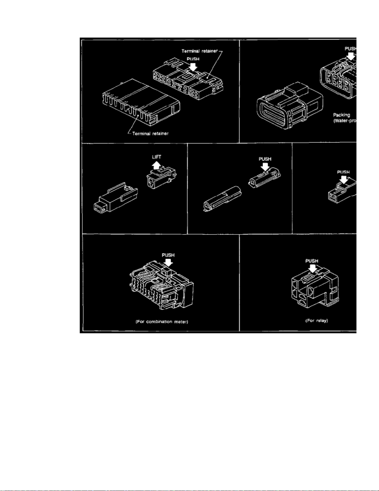
Harness Connector
^ All harness connectors have been modified to prevent accidental looseness or disconnection.
^ The connector can be disconnected by pushing or lifting the locking section.
Do not pull the harness when disconnecting the connector.CAUTION:
Standardized Relays
Page 89

> Relays and Modules > Relays and Modules - Body and Frame > Power Mirror Control Module > Component Information > Diagrams > Diagram Information and
Instructions > Page 95
Maxima SE V6-2968cc 3.0L DOHC MFI (VQ30DE) (1997)
Page 90

Norman Open, Normal Closed And Mixed Type Relays
Relays can mainly be divided into three types: normal open, normal closed and mixed type relays.
Type Of Standardized Relays part 1
Page 91

> Relays and Modules > Relays and Modules - Body and Frame > Power Mirror Control Module > Component Information > Diagrams > Diagram Information and
Instructions > Page 96
Maxima SE V6-2968cc 3.0L DOHC MFI (VQ30DE) (1997)
Page 92

Standardized Relay Description
TYPE OF STANDARDIZED RELAYS
Page 93

Page 94
> Relays and Modules > Relays and Modules - Body and Frame > Power Mirror Control Module > Component Information > Diagrams > Diagram Information and Instructions > Page 97
Power Mirror Control Module: Connector Views
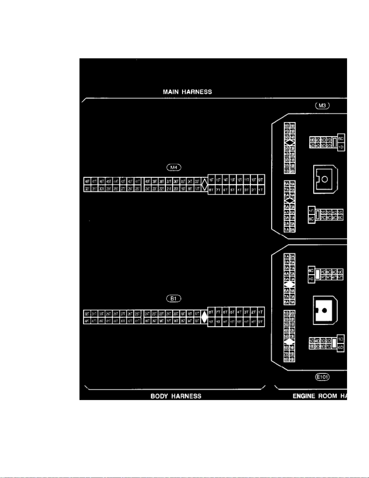
Super Multiple Junction (SMJ) Terminal Arrangement
Page 95

> Relays and Modules > Relays and Modules - Body and Frame > Power Mirror Control Module > Component Information > Diagrams > Diagram Information and
Instructions > Page 98
Maxima SE V6-2968cc 3.0L DOHC MFI (VQ30DE) (1997)
Page 96

Page 97

> Relays and Modules > Relays and Modules - Body and Frame > Power Mirror Control Module > Component Information > Diagrams > Diagram Information and
Instructions > Page 99
Maxima SE V6-2968cc 3.0L DOHC MFI (VQ30DE) (1997)
Fuse Block-Junction Box (J/B)
Page 98

Terminal Arrangement
Page 99

> Relays and Modules > Relays and Modules - Body and Frame > Power Mirror Control Module > Component Information > Diagrams > Diagram Information and
Instructions > Page 100
Maxima SE V6-2968cc 3.0L DOHC MFI (VQ30DE) (1997)
Page 100

Electrical Units Terminal Arrangement
 Loading...