

Page 1
2012 LEAF
Information Provided by:
OWNER'S MANUAL
For your safety, read carefully and keep in this vehicle.
Page 2

Information Provided by:
Page 3
Information Provided by:
Page 4
Information Provided by:
Page 5
Information Provided by:
Page 6
Information Provided by:
Page 7
FOREWORD
Information Provided by:
Welcome to the growing family of new NISSAN
owners. This vehicle is delivered to you with
confidence. It was produced using the latest
techniques and strict quality control.
This manual was prepared to help you understand the operation and maintenance of your
vehicle so that you may enjoy many miles of
driving pleasure. Please read through this
manual before operating your vehicle.
A separate Warranty Information Booklet
explains details about the warranties covering your vehicle. The NISSAN Service
and Maintenance Guide explains details
about maintaining and servicing your vehicle. Additionally, a separate Customer
Care/Lemon Law Booklet (U.S. only) will
explain how to resolve any concerns you
may have with your vehicle, as well as
clarify your rights under your state’s lemon
law.
In additional factory installed options, your
vehicle may also be equipped with additional
accessories installed by NISSAN or by your
NISSAN certified LEAF dealer prior to delivery. It
is important that you familiarize yourself with all
disclosures, warnings, cautions, and instructions
concerning proper use of such accessories prior
to operating the vehicle and/or accessory. See a
NISSAN certified LEAF dealer for details con-
cerning the particular accessories with which
your vehicle is equipped.
Your NISSAN certified LEAF dealer knows your
vehicle best. When you require any service or
have any questions, we will be glad to assist you
with the extensive resources available to us.
READ FIRST — THEN DRIVE SAFELY
Before driving your vehicle, read your Owner’s
Manual carefully. This will ensure familiarity with
controls and maintenance requirements, assisting you in the safe operation of your vehicle.
WARNING
IMPORTANT SAFETY INFORMATION
REMINDERS FOR SAFETY!
Follow these important driving rules to
help ensure a safe and comfortable trip
for you and your passengers!
. NEVER drive under the influence of
alcohol or drugs.
. ALWAYS observe posted speed lim-
its and never drive too fast for
conditions.
. ALWAYS give your full attention to
driving and avoid using vehicle
features or taking other actions that
could distract you.
. ALWAYS use your seat belts and
appropriate child restraint systems.
Pre-teen children should be seated
in the rear seat.
. ALWAYS provide information about
the proper use of vehicle safety
features to all occupants of the
vehicle.
. ALWAYS review this Owner’s Man-
ual for important safety information.
MODIFICATION OF YOUR VEHICLE
This vehicle should not be modified. Modification could affect its performance,
safety or durability, and may even violate
governmental regulations. In addition, damage or performance problems resulting
from modification may not be covered
under NISSAN warranties.
WHEN READING THE MANUAL
This manual includes information for all
options available on this model. Therefore,
you may find some information that does
not apply to your vehicle.
Page 8
All information, specifications and illustrations in
Information Provided by:
this manual are those in effect at the time of
printing. NISSAN reserves the right to change
specifications or design at any time without
notice.
IMPORTANT INFORMATION ABOUT
THIS MANUAL
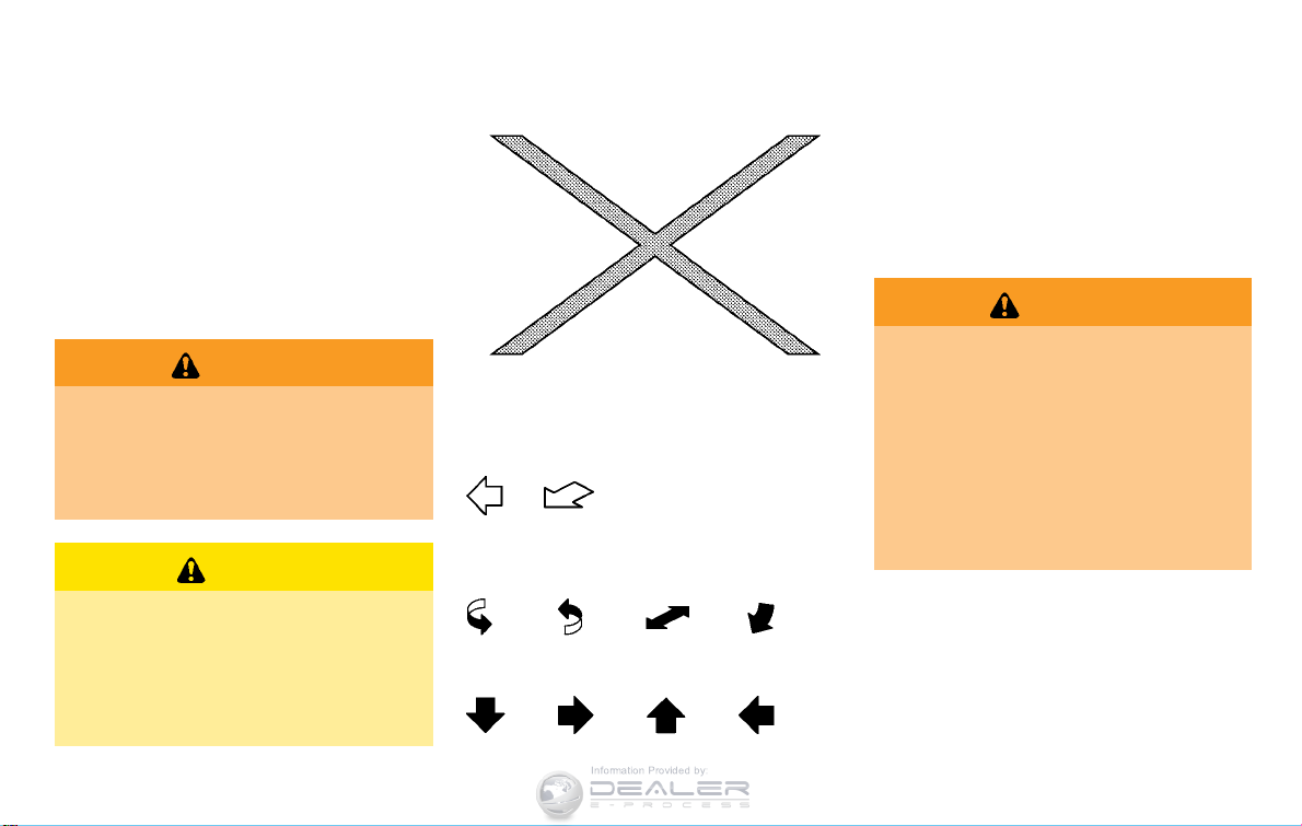
You will see various symbols in this manual. They
are used in the following ways:
WARNING
This is used to indicate the presence of
a hazard that could cause death or
serious personal injury. To avoid or
reduce the risk, the procedures must
be followed precisely.
CAUTION
This is used to indicate the presence of
a hazard that could cause minor or
moderate personal injury or damage to
your vehicle. To avoid or reduce the risk,
the procedures must be followed carefully.
If you see the symbol above, it means “Do not
do this” or “Do not let this happen”.
If you see a symbol similar to those above in an
illustration, it means the arrow points to the front
of the vehicle.
Arrows in an illustration that are similar to those
above indicate movement or action.
Arrows in an illustration that are similar to those
above call attention to an item in the illustration.
[]:
Indicates a key/item displayed on the screen.
CALIFORNIA PROPOSITION 65
WARNING
WARNING
Certain vehicle components contain or
emit chemicals known to the State of
California to cause cancer and birth
defects or other reproductive harm. In
addition, certain fluids contained in
vehicles and certain products of component wear contain or emit chemicals
known to the State of California to
cause cancer and birth defects or other
reproductive harm.
Page 9

CALIFORNIA PERCHLORATE ADVI-
Information Provided by:
SORY
Some vehicle parts, such as lithium batteries, may contain perchlorate material.
The following advisory is provided: “Perchlorate Material - special handling may
apply, see www.dtsc.ca.gov/
hazardouswaste/perchlorate.”
Bluetooth®is a trademark owned
by Bluetooth SIG, Inc.
C
*
2011 NISSAN MOTOR CO., LTD.
All rights reserved. No part of this Owner’s
Manual may be reproduced or stored in a
retrieval system, or transmitted in any form, or
by any means, electronic, mechanical, photocopying, recording or otherwise, without the
prior written permission of Nissan Motor Co.,
Ltd.
Page 10

NISSAN CUSTOMER CARE PROGRAM
Information Provided by:
NISSAN CARES ...
Both NISSAN and your NISSAN certified LEAF dealer are dedicated to serving all your automotive needs. Your satisfaction with your vehicle and your
NISSAN certified LEAF dealer are our primary concerns. Your NISSAN certified LEAF dealer is always available to assist you with all your automobile sales
and service needs.
However, if there is something that your
NISSAN certified LEAF dealer cannot assist
you with or you would like to provide NISSAN
directly with comments or questions, please
contact the NISSAN Consumer Affairs Department using our toll-free number:
For U.S. customers
1-877-NOGASEV
(1-877-664-2738)
For Canadian customers
1-800-387-0122
The Consumer Affairs Department will ask for
the following information:
. Your name, address, and telephone number
. Vehicle identification number (attached to
the top of the instrument panel on the
driver’s side)
. Date of purchase
. Current odometer reading
. Your NISSAN certified LEAF dealer’s name
. Your comments or questions
OR
You can write to NISSAN with the information at:
For U.S. customers
Nissan North America, Inc.
Consumer Affairs Department
P.O. Box 685003
Franklin, TN 37068-5003
or via e-mail at:
nnaconsumeraffairs@nissan-usa.
com
For Canadian customers
Nissan Canada Inc.
5290 Orbitor Drive
Mississauga, Ontario L4W 4Z5
or via e-mail at:
information.centre@nissancanada.
com
If you prefer, visit us at:
www.nissanusa.com (for U.S. customer) or
www.nissan.ca (for Canadian customers)
We appreciate your interest in NISSAN and
thank you for buying a quality NISSAN vehicle.
Page 11

Information Provided by:
Page 12

Table of
Information Provided by:
Illustrated table of contents
0
Contents
EV Overview
Charging
Safety—Seats, seat belts and supplemental restraint system
Instruments and controls
Pre-driving checks and adjustments
Ventilators and climate control systems
Starting and driving
In case of emergency
Appearance and care
Maintenance and do-it-yourself
Technical and consumer information
EV
CH
1
2
3
4
5
6
7
8
9
Index
10
Page 13

Information Provided by:
Page 14

0 Illustrated table of contents
Information Provided by:
Seats, seat belts and Supplemental Restraint
System (SRS) ........................................................................... 0-2
Exterior front .............................................................................. 0-3
Exterior rear ............................................................................... 0-4
Passenger compartment ........................................................ 0-5
Cockpit ....................................................................................... 0-6
Instrument panel ...................................................................... 0-7
Meters and gauges ................................................................. 0-8
Motor compartment ................................................................ 0-9
Warning and indicator lights ............................................. 0-10
Page 15

SEATS, SEAT BELTS AND
Information Provided by:
SUPPLEMENTAL RESTRAINT
SYSTEM (SRS)
10. Rear seats (P.1-4)
11. Front seat-mounted side-impact supplemental air
bags (P.1-36)
12. Occupant classification sensors (weight sensors)
— Advanced Air Bag System (P.1-42)
13. Front passenger air bag status light (P.1-42)
1. Rear headrests (Page.1-4)
2. Child restraint anchor points (for top tether strap
child restraint) (P.1-32)
3. Roof-mounted curtain side-impact supplemental
air bags (P.1-36)
4. Seat belts (P.1-10)
0-2 Illustrated table of contents
5. Front head restraints (P.1-4)
6. Seat belt pretensioners (P.1-49)
7. Front seats (P.1-3)
8. Supplemental front-impact air bags (P.1-36)
9. LATCH (Lower Anchors and Tethers for CHildren)
system (P.1-21)
Page 16

EXTERIOR FRONT
Information Provided by:
9. Fog lights*
— Switch operation (P.2-44)
— Bulb replacement (P.8-22)
10. Tires
— Wheels and tires (P.8-25, P.9-5)
— Flat tire (P.6-2)
— Tire Pressure Monitoring System (TPMS)
(P.2-16, P.5-2)
11. Side turn signal light
— Switch operation (P.2-44)
— Bulb replacement (P.8-22)
12. Doors
— Keys (P.3-2)
— Door locks (P.3-4)
— Intelligent Key system (P.3-6)
— Security system (P.2-35)
13. Child safety rear door lock (P.3-6)
*: if so equipped
1. Charge port lid (P.3-17)
2. Hood (P.3-16)
3. Headlight and turn signal lights
— Switch operation (P.2-41)
— Bulb replacement (P.8-21)
4. Windshield wiper and washer
— Switch operation (P.2-38)
— Blade replacement (P.8-12)
— Window washer fluid (P.8-10)
5. Outside mirrors (P.3-21)
6. Power windows (P.2-53)
7. License plate installation (P.9-9)
8. Recovery hook (P.6-15)
Illustrated table of contents 0-3
Page 17

EXTERIOR REAR
Information Provided by:
8. Rear hatch (P.3-17)
— Intelligent Key system (P.3-6)
*: if so equipped
1. Rear view camera* (See LEAF Navigation System
Owner’s Manual.)
2. Rear window wiper and washer
— Switch operation (P.2-39)
— Window washer fluid (P.8-10)
3. High-mounted stop light
— Bulb replacement (P.8-22)
0-4 Illustrated table of contents
4. Rear window defroster (P.2-40)
5. Solar cell module* (P.EV-29)
6. Antenna
— Satellite radio antenna (See LEAF Navigation
System Owner’s Manual.)
7. Rear combination lights
— Bulb replacement (P.8-22)
Page 18

PASSENGER COMPARTMENT
Information Provided by:
— EVSE (Electric Vehicle Supply Equipment) (P.
CH-11)
7. Tools (P.6-13)
8. Heated seat switch (P.2-46)
9. Console box (P.2-49)
10. Door armrest
— Power window switch (P.2-53)
— Power door lock switch (P.3-5)
— Outside mirror remote control switch (P.3-21)
11. Front cup holders (P.2-49)
*: if so equipped
1. Ceiling light (P.2-57)
2. Sun visors (P.3-20)
3. Map lights (P.2-56)
— Bluetooth
®
Hands-Free Phone System microphone (See LEAF Navigation System Owner’s
Manual.)
4. Sunglasses holder (P.2-50)
5. Inside rearview mirror (P.3-20)
— HomeLink
®
* (P.2-58)
6. Cargo area
— Cargo cover* (P.2-51)
— Parking brake mechanical release (P.6-16)
Illustrated table of contents 0-5
Page 19

COCKPIT
Information Provided by:
— Horn (P.2-46)
— Driver’s supplemental air bag (P.1-36)
7. Wiper and washer switch (P.2-38)
8. Steering-wheel-mounted controls (right side)
— Cruise control switches (P.5-17)
9. Fuse box cover (P.8-16)
10. Vehicle Dynamic Control (VDC) OFF switch
(P.2-48)
11. Headlight aiming control (P.2-44)
12. Immediate charge switch (P.CH-24)
13. Heated steering wheel switch (P.2-45)
14. Tilting steering wheel lever (P.3-19)
15. Heated seat switch (P.2-46)
16. Selector lever (P.5-12)
17. Electric parking brake (P.5-15)
*: if so equipped
1. TRIP switch for twin trip odometer (P.2-6)
2. Trip computer switch (P.2-27)
3. Instrument brightness control switch (P.2-41)
4. Headlight, fog light* and turn signal switch
— Headlight (P.2-41)
— Turn signal light (P.2-44)
— Fog light* (P.2-44)
0-6 Illustrated table of contents
5. Steering-wheel-mounted controls (left side) (See
LEAF Navigation System Owner’s Manual.)
—
Driving range button
— Audio control
— Bluetooth
®
Hands-Free Phone System control
6. Steering wheel
— Electric power steering system (P.5-21)
Page 20

INSTRUMENT PANEL
Information Provided by:
9. Power switch (P.5-7)
®
10. iPod
connector/USB connector (See LEAF
Navigation System Owner’s Manual.)
11. Rear window defroster switch (P.2-40)
12. Power outlet (P.2-48)
13. Auxiliary input jack (See LEAF Navigation System
Owner’s Manual.)
14. Front passenger air bag status light (P.1-44)/
Approaching Vehicle Sound for Pedestrians (VSP)
system warning light (P.2-14)
15. Heater and air conditioner control (P.4-3)
16. Glove box (P.2-51)
1. Side ventilator (P.4-2)
2. Meters and gauges (P.2-5)
3. Center multi-function control panel (See LEAF
Navigation System Owner’s Manual.)
— Navigation system
— Vehicle information and setting buttons
— Bluetooth
®
Hands-Free Phone System
— Audio system
4. Hazard warning flasher switch (P.2-45)
5. Center ventilator (P.4-2)
6. Front passenger supplemental air bag (P.1-36)
7. Charge port lid opener handle (P.3-17)
8. Hood release handle (P.3-16)
Illustrated table of contents 0-7
Page 21

METERS AND GAUGES
Information Provided by:
10. READY to drive indicator light (P.2-20)
11. Dot matrix liquid crystal display (P.2-22)
— Odometer/twin trip odometer (P.2-6)
— Trip computer (P.2-27)
— Shift position indicator (P.2-27)
— Indicator for timer (P.2-34)
12. Driving range (P.2-8)
13. Li-ion battery available charge gauge (P.2-9)
14. Li-ion battery capacity level gauge (P.2-10)
Upper display and lower display
This vehicle is equipped with an upper display
and a lower display.
1. Master warning light (P.2-18)
2. ECO indicator (P.2-10)
3. Speedometer (P.2-6)
0-8 Illustrated table of contents
4. Clock (P.2-11)
5. Outside air temperature (P.2-10)
6. Turn signal/Hazard indicator light (P.2-20)
7. Li-ion battery temperature gauge (P.2-7)
8. Warning/indicator lights (P.2-12)
9. Power meter (P.2-7)
Page 22

MOTOR COMPARTMENT
Information Provided by:
1. Coolant tank cap (P.8-7)
2. Window washer fluid reservoir (P.8-10)
3. Brake fluid reservoir (P.8-9)
4. Traction motor inverter (P.EV-7)
5. Traction motor and reduction gear (P.8-9)
6. Charge port lid (P.3-17)
7. Coolant reservoir (P.8-7)
8. 12-volt battery (P.8-11)
— Jump starting (P.6-9)
9. Fuse/fusible link holder (P.8-16)
Illustrated table of contents 0-9
Page 23
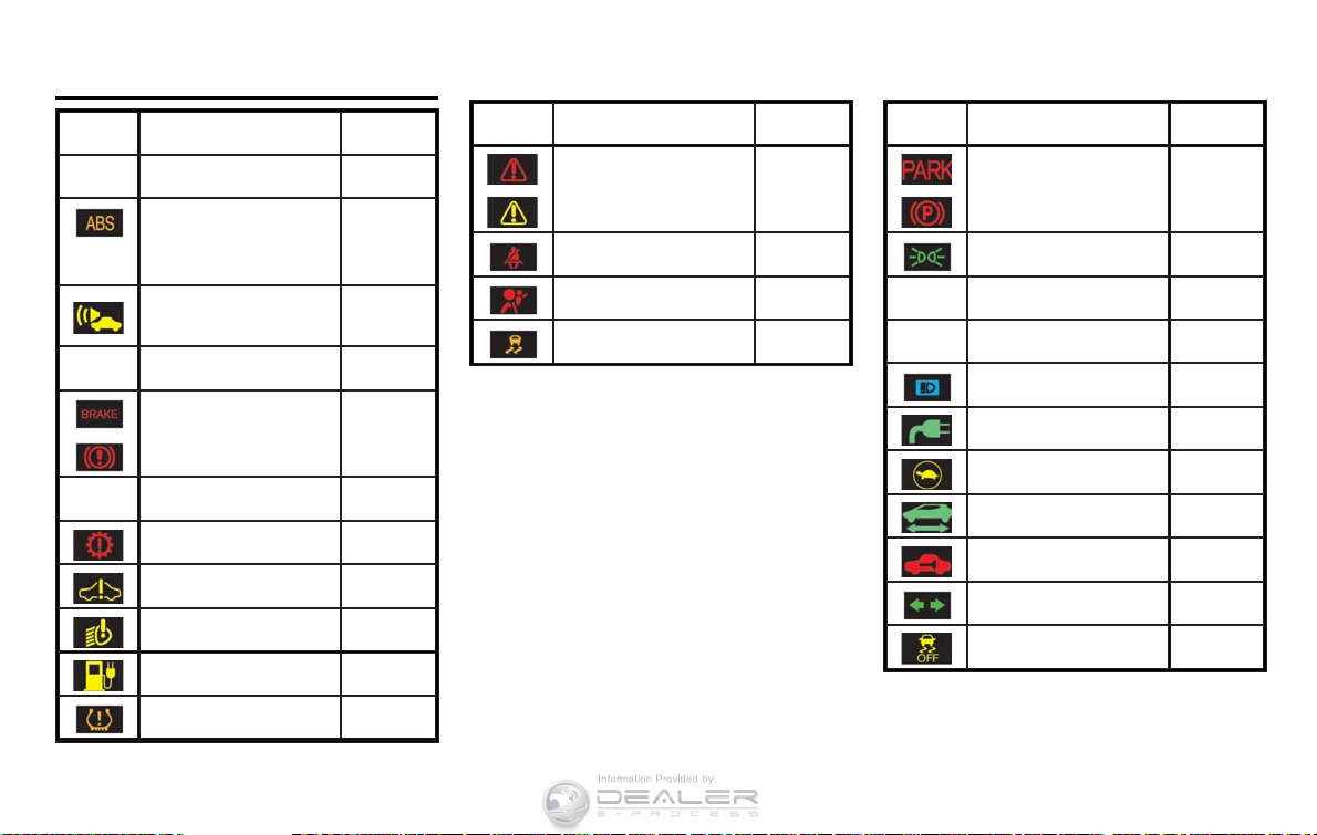
WARNING AND INDICATOR LIGHTS
Information Provided by:
Warning
light
12-volt battery charge
warning light
Anti-lock Braking System
(ABS) warning light
Approaching Vehicle
Sound for Pedestrians
(VSP) system warning light
BRAKE system warning
light (yellow)
Name Page
2-13
2-14
2-14
2-14
Warning
light
Name Page
Master warning light (red/
yellow)
Seat belt warning light 2-18
Supplemental air bag
warning light
Vehicle Dynamic Control
(VDC) warning light
2-18
2-18
2-19
Indicator
light
Name Page
Electric parking brake indicator light
Exterior light indicator 2-19
Front fog light indicator
light (if so equipped)
Front passenger air bag
status light
High beam indicator light 2-19
2-19
2-19
2-19
BRAKE warning light (red) 2-15
Electric power steering
warning light
Electric shift control system warning light
EV system warning light 2-16
Headlight warning light 2-16
Low battery charge warning light
Low tire pressure warning
light
0-10 Illustrated table of contents
2-15
2-16
2-16
2-16
Plug in indicator light 2-19
Power limitation indicator
light
READY to drive indicator
light
Security indicator light 2-20
Turn signal/hazard indicator lights
Vehicle Dynamic Control
(VDC) off indicator light
2-19
2-20
2-20
2-21
Page 24

EV Overview
Information Provided by:
The EV (Electric Vehicle) system ...................................... EV-2
Li-ion battery .......................................................................... EV-2
High voltage precautions .................................................... EV-7
Road accident precautions ................................................ EV-8
EV (Electric Vehicle) characteristics ................................ EV-9
Life with an EV (scene guide) ........................................ EV-10
Driving with a discharged Li-ion battery ................... EV-3
Charging the 12-volt battery ........................................ EV-5
Li-ion battery heater ....................................................... EV-5
High-voltage components ............................................. EV-7
Emergency shut-off system .......................................... EV-9
Noise and vibration ...................................................... EV-10
Charging the Li-ion battery ........................................ EV-10
Before driving your vehicle ........................................ EV-13
Starting your vehicle .................................................... EV-16
Driving the vehicle ........................................................ EV-17
At home after driving ................................................. EV-21
Efficient use of your vehicle ............................................ EV-22
Range ............................................................................ EV-22
Improve driving range ............................................... EV-22
Li-ion battery life ......................................................... EV-23
Li-ion battery maintenance ...................................... EV-24
EV unique information ...................................................... EV-24
Meters and indicators ............................................... EV-24
Approaching Vehicle Sound for Pedestrians
(VSP) system .............................................................. EV-27
Electric shift control system .................................... EV-28
Electric parking brake ............................................... EV-28
LED headlight (low beam) ....................................... EV-29
Solar cell module (if so equipped) ........................ EV-29
Driving range button ................................................ EV-29
Page 25
THE EV (Electric Vehicle) SYSTEM LI-ION BATTERY
Information Provided by:
The LEAF is an electric vehicle. Some of the
vehicle’s systems operate differently and have
different operating characteristics than vehicles
equipped with an internal combustion engine. It
is important to carefully review the entire Owner’s Manual for this reason. The main difference
is the LEAF is powered by electricity. The LEAF
does not require and it is not capable of using
gasoline like a vehicle powered by a traditional
internal combustion engine. The LEAF uses
electricity stored in the lithium ion (Li-ion)
battery. The vehicle Li-ion battery must be
charged with electricity before the vehicle can
be driven. As the vehicle operates, the Li-ion
battery gradually discharges. If the Li-ion battery
becomes completely discharged, the vehicle will
not operate until it is re-charged. The charging
process usually takes from approximately 30
minutes to 21 hours as described more fully in
this manual.
This vehicle uses two types of batteries. One is
the 12-volt battery that is the same as the
battery in vehicles powered by gasoline engines,
the other is the Li-ion battery (high voltage).
The 12-volt battery provides power to the
vehicle systems and features such as the audio
system, supplemental restraint systems, headlights and windshield wipers.
EV-2 EV Overview
The Li-ion battery provides power to the electric
motor (traction motor) that moves the vehicle.
The Li-ion battery also charges the 12-volt
battery.
The vehicle must be plugged in for the Li-ion
battery to be charged. Additionally, the vehicle
system can extend the vehicle range by converting driving force into electricity that is stored
in the Li-ion battery while the vehicle is
decelerating or being driven downhill. This is
called regenerative brake. This vehicle is considered to be an environmentally friendly vehicle
because it does not emit exhaust gases, such as
carbon dioxide and nitrogen oxide.
Your vehicle contains a sealed Li-ion
high voltage battery. If the Li-ion battery is disposed of improperly, there is a
risk of severe burns and electrical
shock that may result in serious injury
or death and there is also a risk of
environmental damage.
To prevent damage to the Li-ion battery:
. Do not expose a vehicle to ambient
temperatures above 1208F (498C) for
over 24 hours.
. Do not store a vehicle in tempera-
tures below −138F(−258C) for over
seven days.
. Do not leave your vehicle for over 14
days where the Li-ion battery available charge gauge reaches a zero or
near zero (state of charge).
. Do not use the Li-ion battery for any
other purpose.
WARNING
CAUTION
Page 26

NOTE:
Information Provided by:
. If the outside temperature is − 138F
(−258C) or less, the Li-ion battery may
freeze and it cannot be charged or
provide power to run the vehicle. Move
the vehicle to a warm location.
. The capacity of the Li-ion battery in
your vehicle to hold a charge will, like
all such batteries, decrease with time
and usage. As the battery ages and
capacity decreases, this will result in a
decrease from the vehicle’s initial mileage range. This is normal, expected,
and not indicative of any defect in your
Li-ion battery. NISSAN estimates that
battery capacity will be approximately
80% of original capacity after five
years, although this is only an estimate,
and this percentage may vary (and
could be significantly lower) depending
on individual vehicle and Li-ion battery
usage.
. The Li-ion battery has limited service
life, and when its charging capacity
falls below a specific level, the EV
system warning light will illuminate.
Owners should bring their vehicle in for
inspection and possible battery repla-
cement.
. The Li-ion battery has a limited service
life. Contact a NISSAN certified LEAF
dealer for information about recycling
or disposal of the Li-ion battery. Do not
attempt to recycle or dispose of the Liion battery yourself.
DRIVING WITH A DISCHARGED LIION BATTERY
When a destination is set in the navigation
system that exceeds the available vehicle range,
the navigation system automatically searches
the location of nearby charging stations. When
the nearby charging station locations are displayed, charge the Li-ion battery as soon as
possible.
Warning lights illuminate on the instrument panel
and messages are displayed on the dot matrix
liquid crystal display to inform you that the Li-ion
battery charge is low. Instructions are also
displayed on the navigation system screen to
direct you to nearby charging stations.
The vehicle’s range is very limited when these
warning lights illuminate and messages are
displayed. Follow the instructions on the navigation screen and immediately charge the vehicle
at the nearest charging station.
There are three levels of information that will be
displayed as the Li-ion battery becomes discharged:
1. The following warning lights illuminate on
the instrument panel and messages are
displayed on the dot matrix liquid crystal
system screen display at the same time to
EV Overview EV-3
Page 27

indicate low Li-ion battery charge:
Information Provided by:
.
The low battery charge warning light
.
The master warning light
.
“Li-ion battery level is Low” warning
message is displayed on the dot matrix
liquid crystal display
See “16. Li-ion battery low charge
warning ” in the “2. Instruments and
controls” section.
.
Messages are displayed on navigation
system screen
See “Low battery warning” in the “2.
Instruments and controls” section.
EV-4 EV Overview
.
The driving range flashes
*
1
.
NOTE:
Due to traffic conditions, it may be
difficult to get to the charging station
suggested by the navigation system. If
the Li-ion battery is almost completely
discharged, drive directly to the nearest
charging station.
2. If the vehicle is driven and the Li-ion battery
continues to discharge, the driving range on
the instrument panel changes to “---”
*
2
.
3. When the power limitation indicator light
illuminates, traction motor output is
limited resulting in reduced vehicle speed.
Stop the vehicle in a safe location before the
Li-ion battery becomes completely discharged and there is no power available to
drive the vehicle. Contact Roadside assistance service shown in your NISSAN
Warranty Information Booklet. See “If the
Li-ion battery becomes completely discharged” in the “6. In case of emergency”
section.
Page 28
CHARGING THE 12-VOLT BATTERY
Information Provided by:
The 12-volt battery is charged automatically
using electricity stored in the Li-ion battery.
When the 12-volt battery is being charged, the
charge status indicator light on the instrument
panel flashes. (except when charging the Li-ion
battery or the power switch is in the READY to
drive position.) See “Charging status indicator
lights” in the “CH. Charging” section.
While vehicle is in use
The Li-ion battery charges the 12-volt battery as
necessary when the power switch is in the
READY to drive position or ON position.
The 12-volt battery is not charged in the
following conditions.
. When the power switch is in ACC position.
. When the power switch is in ON position
and shift position is in the N (Neutal)
position.
While the vehicle is not in use
When the EV (Electric Vehicle) system is off for
an extended time, the 12-volt battery may be
automatically charged for a short period of time
on a regular basis.
LI-ION BATTERY HEATER
CAUTION
The Li-ion battery heater does not
operate if the available Li-ion battery
charge is less than approximately 30%
and the charger is not connected to the
vehicle. To help prevent the Li-ion
battery from freezing, do not leave the
vehicle in an environment if temperatures may go below -48F (-208C) unless
the vehicle is connected to a charger.
The Li-ion battery heater helps to prevent the Liion battery from freezing and helps to prevent
significant reductions in the Li-ion battery output
when the temperature is cold. The Li-ion battery
heater automatically turns on when the Li-ion
battery temperature is approximately -48F
(-208C) or colder. The Li-ion battery heater
automatically turns off when the Li-ion battery
temperture is approximately 148F (-108C) or
higher.
The Li-ion battery heater uses electrical power
from an external source when a charger is
connected to the vehicle. The Li-ion battery
heater uses electrical power from the Li-ion
battery when the charger is not connected to the
vehicle.
NOTE:
. Connect the charger to the vehicle and
place the power switch in the OFF
position when parking the vehicle if
temperatures may go below -48 F
(-208C). This provides external power
to the Li-ion battery heater when it
operates and does not discharge the
Li-ion battery.
. The charging status indicator lights
illuminate in a specific pattern when
the Li-ion battery heater operates. The
charging status indicator lights use the
same pattern to indicate 12-volt battery
charging, Climate Ctrl. Timer operation
or Remote Climate Control operation.
The charging status indicator lights do
not change if the Li-ion battery heater
operates at the same time as the above
features. See “Charging status indicator lights” in the “CH. Charging” section.
. The Li-ion battery heater uses Li-ion
battery power to operate, even if the
vehicle is connected to a charger when:
EV Overview EV-5
Page 29

— the vehicle’s power switch is in the
Information Provided by:
ON position.
— there is no electrical power being
supplied to the charging equipment.
. When the Li-ion battery heater is
already in operation using an external
power source, it will continue to use
the external power even if the power
switch is placed in the ON position.
. Vehicle driving range is reduced if the
Li-ion battery heater operates (Li-ion
battery temperature approximately -48F
(-208C) or colder) while driving the
vehicle. You may need to charge the
Li-ion battery sooner than in warmer
temperatures.
. The Li-ion battery requires more time
to charge when the Li-ion battery
heater operates.
. The predicted charging time displayed
on the meter and navigation system
increases when the Li-ion battery heater operates.
. Climate control performance is re-
duced when using the Climate Ctrl.
Timer or Remote Climate Control while
the Li-ion battery heater operates.
EV-6 EV Overview
. The Li-ion battery may not charge to
the expected level using the charging
timer when a [Start Time] and [End
Time] are set while the Li-ion battery
heater operates.
. Set only the charging timer [End Time]
when charging in cold weather. The
vehicle automatically determines when
to start charging to fully charge the Liion battery, even if the Li-ion battery
heater operates. Charging ends before
the set end time if the Li-ion battery is
fully charged.
Page 30

HIGH VOLTAGE PRECAUTIONS
Information Provided by:
HIGH-VOLTAGE COMPONENTS
WARNING
. The EV (Electric Vehicle) system
uses high voltage up to approximately DC 400 volt. The system can
be hot during and after starting and
when the vehicle is shut off. Be
careful of both the high voltage
and the high temperature. Follow
the warning labels that are attached
to the vehicle.
. Never disassemble, remove or re-
place high-voltage parts and cables
as well as their connectors because
they can cause severe burns or
electric shock that may result in
serious injury or death. High-voltage
cables are colored orange. The
vehicle high voltage system has no
user serviceable parts. Take your
vehicle to a NISSAN certified LEAF
dealer for any necessary maintenance.
High-voltage components
1. Traction motor inverter
2. Traction motor and reduction gear
3. High-voltage wire harnesses (colored orange)
4. Li-ion battery
5. Service plug
6. On-board charger
EV Overview EV-7
Page 31

ROAD ACCIDENT PRECAUTIONS
Information Provided by:
WARNING
In case of a collision:
. If your vehicle is drivable, pull your
vehicle off the road, push the P
(Park) position switch on the selector lever, apply the parking brake
and turn the EV (Electric Vehicle)
system off.
. Check your vehicle to see if there
are exposed high-voltage parts or
cables. For their locations, see
“High-voltage components” earlier
in this section. To avoid personal
injury, never touch high-voltage wiring, connectors, and other highvoltage parts, such as inverter unit
and Li-ion battery. An electric shock
may occur if exposed electric wires
are visible when viewed from inside
or outside of your vehicle. Therefore, never touch exposed electric
wires.
. If the vehicle receives a strong
impact to the floor while driving,
stop the vehicle in a safe location
and check the floor.
EV-8 EV Overview
. Leaks or damage to the Li-ion
battery may result in a fire. If you
discover them, contact emergency
services immediately. Since the
fluid leak may be lithium manganate from the Li-ion battery, never
touch the fluid leak inside or outside the vehicle. If the fluid contacts
your skin or eyes, wash it off
immediately with a large amount of
water and receive immediate medical attention to help avoid serious
injury.
. If a fire occurs in the EV (Electric
Vehicle), leave the vehicle as soon
as possible. Only use a type ABC,
BC or C fire extinguisher that is
meant for use on electrical fires.
Using a small amount of water or
the incorrect fire extinguisher can
result in serious injury or death from
electrical shock.
. If your vehicle needs to be towed,
do it with the front wheels raised. If
the front wheels are on the ground
when towing, the traction motor
may generate electricity. This may
damage the components of the EV
(Electric Vehicle) system and cause
a fire.
. If you are not able to safely assess
the vehicle due to vehicle damage,
do not touch the vehicle. Leave the
vehicle and contact emergency services. Advise 1st responders that
this is an electric vehicle.
. In the event of an accident that
requires body repair and painting,
the vehicle should be delivered to a
NISSAN certified LEAF dealer to
have the Li-ion battery pack and
high voltage parts such as the
inverter, including the wiring harness, removed prior to painting. Liion battery packs exposed to heat in
the paint booth will experience
capacity loss. Damaged Li-ion battery packs may also pose safety
risks to untrained mechanics and
repair personnel.
Page 32

EMERGENCY SHUT-OFF SYSTEM
Information Provided by:
The emergency shut-off system is activated and
the high-voltage system automatically turns off in
the following conditions:
- Front and side collisions in which the air bags
are deployed.
- Certain rear collisions.
- Certain EV (Electric Vehicle) system malfunctions
For the above collisions and certain other EV
(Electric Vehicle) system malfunctions, the
READY to drive indicator light will turn off. See
“Warning/indicator lights and audible reminders” in the “2. Instruments and controls”
section.
The emergency shut-off activates for the above
collisions to minimize risk of an event that could
cause injury or an accident. If the emergency
shut-off system activates, the EV system may
not be switched to READY to drive position,
contact a NISSAN certified LEAF dealer. Even if
the power switch is switched to READY to drive
position, the system may shut-off suddenly.
Therefore, drive cautiously to the nearest
NISSAN certified LEAF dealer or contact a
NISSAN certified LEAF dealer as soon as
possible.
EV (Electric Vehicle)
CHARACTERISTICS
WARNING
. Pay special attention to pedes-
trians. Because there is no engine
noise, pedestrians may not know
the vehicle is approaching, moving
or about to move, and may step into
the path of vehicle travel.
. When leaving the vehicle, be sure to
turn off the EV (Electric Vehicle)
system.
. Be sure to push the P (Park) posi-
tion switch on the selector lever and
apply the parking brake when parking because the vehicle can move
when the READY to drive indicator
light is ON. When the READY to
drive indicator light is ON, do not
leave your vehicle in a shift position
other than the P (Park) position.
. Keep the brake pedal depressed
until you are ready to drive. When
the vehicle is in the D (drive) position or ECO or R (reverse) position,
if you release the brake pedal and
do not depress accelerator, the
vehicle will creep and may start
abruptly. This may cause serious
injury or death.
NOTE:
. The vehicle cannot run with a dis-
charged Li-ion battery. Repeated acceleration consumes more power from the
Li-ion battery than driving at a steady
speed.
. This vehicle is equipped with a regen-
erative brake system. The primary purpose of regenerative brake system is to
provide some power to recharge the Liion battery and extend driving range. A
secondary benefit is “engine braking”
that operates based on Li-ion battery
conditions.
. In the D (Drive) position, when the
accelerator pedal is released, the regenerative brake system provides
some deceleration.
. When you put the shift selector in the
ECO position and take your foot off the
accelerator pedal, more regenerative
brake is applied than in the D (Drive)
position.
. Less deceleration is provided by the
regenerative brake system when the Li-
EV Overview EV-9
Page 33

ion battery is fully charged. Regenera-
Information Provided by:
tive brake is automatically reduced
when the Li-ion battery is fully charged
to prevent the Li-ion battery from
becoming overcharged. Regenerating
brake is also automatically reduced
when the battery temperature is high/
low (indicated by the red/blue zones
on the Li-ion battery temperature
gauge) to prevent Li-ion battery damage.
. The brake pedal should be used to
slow or stop the vehicle depending on
traffic or road conditions. The vehicle
brakes are not affected by regenerative
brake system operation.
NOISE AND VIBRATION
You might experience the following noise or
vibration as a normal characteristic of this
vehicle.
. Traction motor noise from motor compart-
ment.
. Noise and vibration when releasing and
applying the electric parking brake.
. Water pump and radiator fan noise while
charging.
. Compressor and radiator fan noise when the
Climate Ctrl. Timer or remote climate control
is used.
. Relay operation noise and vibration at start-
up and shut-down of the EV (Electric
Vehicle) system (power switch placed in
the ON and OFF position).
. Approaching Vehicle Sound for Pedestrians
(VSP).
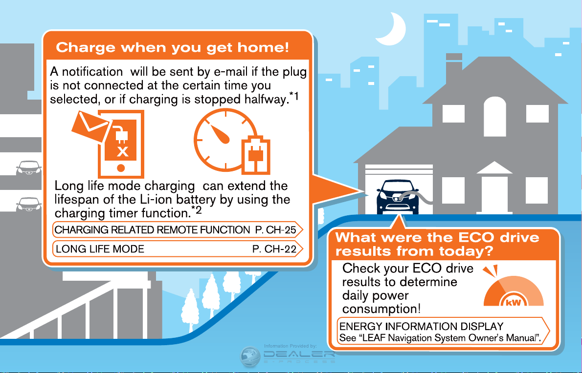
LIFE WITH AN EV (scene guide)
This section provides a brief explanation for the
most important LEAF functions. Refer to the
specific sections of this manual for detailed
explanations of the vehicle features and operation.
CHARGING THE LI-ION BATTERY
WARNING
The EV (Electric Vehicle) system uses a
high voltage current. Failure to follow
the proper handling instructions may
cause serious injury or death. Be sure
to read the “CH. Charging” section and
follow the procedures and guidelines
described.
EV-10 EV Overview
Page 34

Information Provided by:
EV Overview EV-11
Page 35

Information Provided by:
EV-12 EV Overview
Page 36

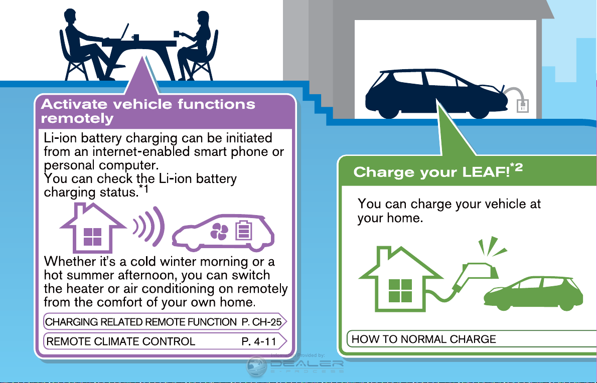
BEFORE DRIVING YOUR VEHICLE
Information Provided by:
The Li-ion battery charging status can be
checked using an internet enabled smart phone
or personal computer at home. You may also
choose to have SMS messages (text messages)
sent to a cellular phone. Additionally, the heater
and air conditioner of the vehicle can be set to
operate using the Climate Ctrl. Timer function or
A/C-heater remote function, if necessary. See
“Remote climate control” in the “4. Ventilators
and climate control systems” section.
NOTE:
. To check the Li-ion battery charging
status or to use the remote heater and
air conditioner using an internet enabled smart phone or personal computer, the following conditions must be
met:
— The vehicle must be located in a
cellular phone or smart phone coverage area.
— The internet enabled cellular phone
or smart phone must be located in a
cellular phone or smart phone coverage area.
— The computer must be connected to
the internet.
— A cellular phone must be used to
communicate with the vehicle.
— A cellular phone capable of text
messaging must be used to receive
text message regarding vehicle
charge status.
. When the remote heater and air condi-
tioner is set, the system operates the
heater and air conditioner to adjust the
in-cabin temperature to a factory preset temperature.
. When the charge connector is discon-
nected from the vehicle, the heater and
air conditioner operates using vehicle
Li-ion battery electric power.
. If the remote heater and air conditioner
function and Li-ion battery charging are
performed at the same time, Li-ion
battery charging will take longer than
usual due to the power used to heat or
cool the vehicle.
EV Overview EV-13
Page 37

Checking Li-ion battery charging
Information Provided by:
status
The Li-ion battery charge status can be checked
on the NISSAN CARWINGS Data Center
website via an internet enabled smart phone or
personal computer.
If the Li-ion battery is not sufficiently charged,
you can start charging the Li-ion battery via the
remote charge function. See “Charging related
remote function” in the “CH. Charging” section.
EV-14 EV Overview
Page 38

Operating the climate control sys-
Information Provided by:
tem before driving
The vehicle heating and air conditioning system
can be turned on via remote control with an
internet enabled smart phone or personal
computer.
This allows the interior of the vehicle to be
heated or cooled while the vehicle is charging.
This reduces the load on the Li-ion battery while
the vehicle is being driven and can help increase
the vehicle driving range. See “Remote climate
control” in the “4. Ventilators and climate control
systems” section.
EV Overview EV-15
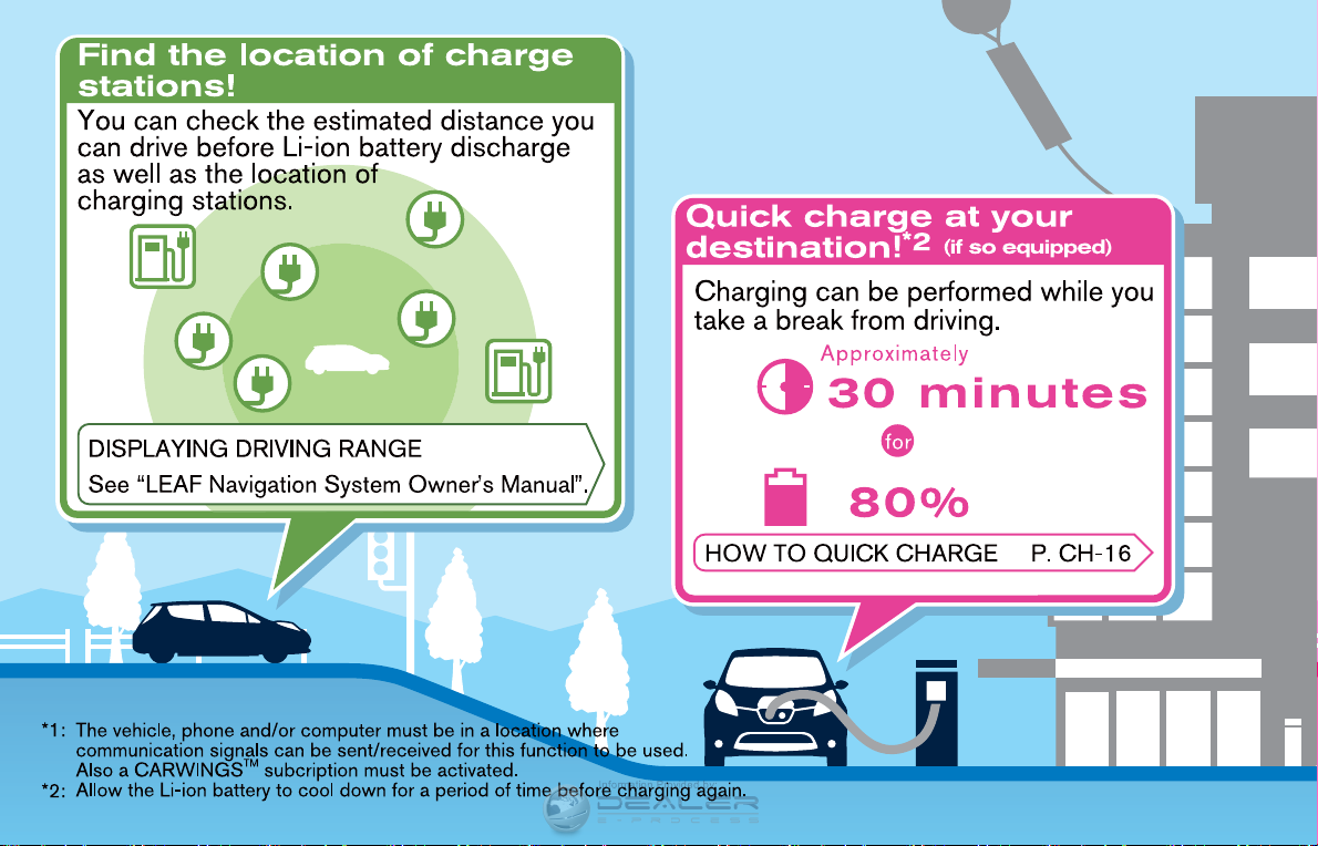
Page 39

Information Provided by:
EV-16 EV Overview
NOTE:
. Before driving, compare the driving
distance to the destination displayed
on the navigation screen with the
estimated driving range shown on the
meter. Determine if it will be necessary
to charge the Li-ion battery before or
while driving to your planned destination.
. If it is necessary to charge the Li-ion
battery, use the navigation system to
search for available charging stations
on your planned driving route.
STARTING YOUR VEHICLE
1. Depress the brake pedal.
2. Press the power switch.
3. Check that the READY to drive indicator
light illuminates and the start up sound is
audible. See “READY to drive indicator light”
in the “2. Instruments and controls” section.
4. If route guidance is necessary, enter the
destination in the navigation system. See
LEAF Navigation System Owner’s Manual.
5. Check the Li-ion battery level and the
estimated driving range shown on the meter.
See “Driving range” in the “2. Instruments
and controls” section.
Page 40

DRIVING THE VEHICLE
Information Provided by:
1. Depress the brake pedal.
2. Release the electric parking brake.
3. Move the selector lever into the D (Drive)
position. When released, the selector lever
returns to its original center position.
4. Confirm that the vehicle is in the D (Drive)
position. The indicator next to the “D” by the
selector lever illuminates and “D” is displayed on the meter.
5. Release the brake pedal.
6. Depress the accelerator pedal and start
driving.
NOTE:
The electric parking brake will automati-
cally be released, when you depress the
accelerator while the vehicle is in the D
(Drive) position, ECO position or R (Reverse) position with the seat belt fastened.
There are two gear positions for driving the
vehicle forward: the D (Drive) position and the
ECO position. See “Driving vehicle” in the “5.
Starting and driving” section.
. Use the D (Drive) position for optimum
driving performance.
. Use the ECO position for maximum vehicle
range and for city driving. When the ECO
position is used, more regenerative brake is
applied when the accelerator pedal is
released in comparison to the D (Drive)
position. This provides additional energy to
the Li-ion battery, helping to increase the Liion battery charge and helps to extend the
vehicle range.
EV Overview EV-17
Page 41

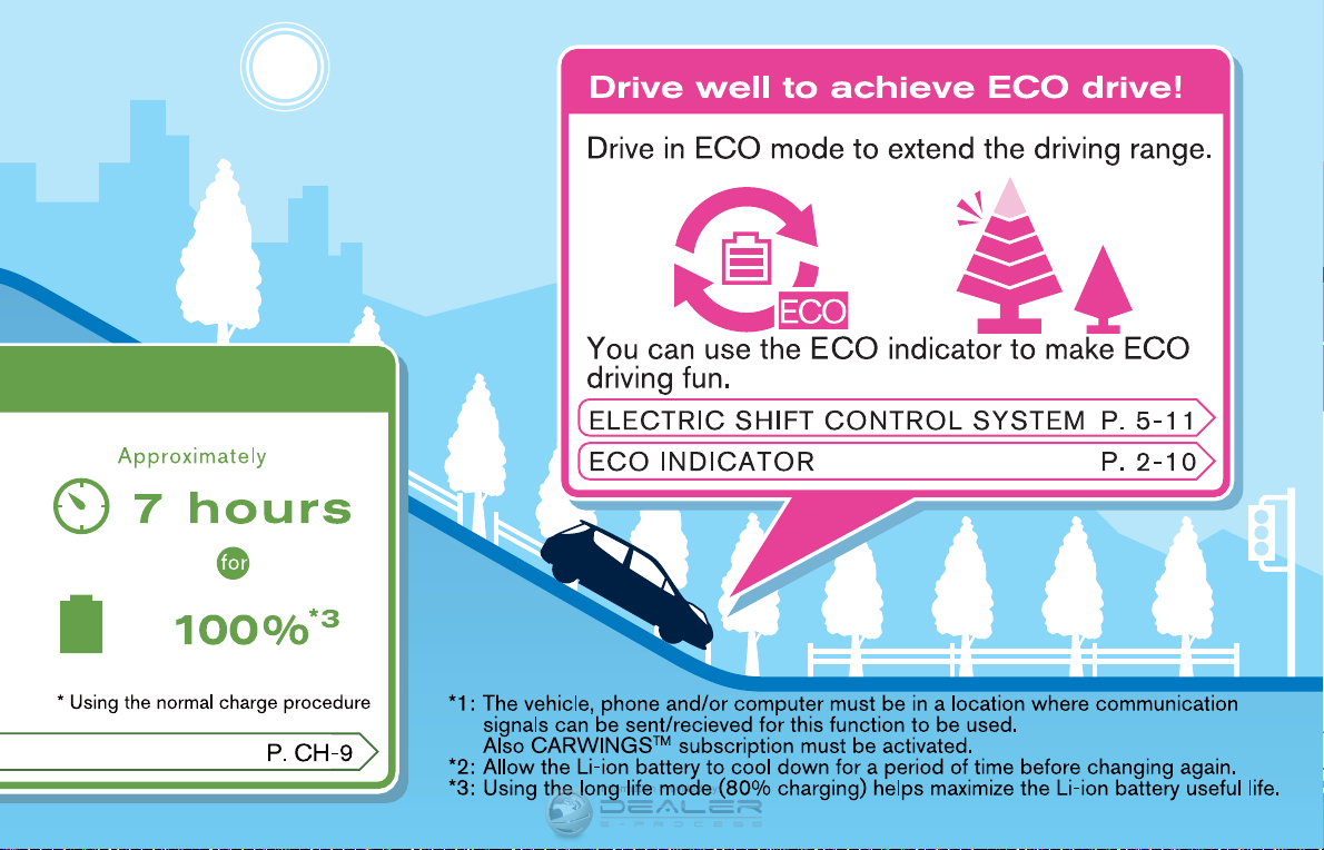
The ECO position helps extend vehicle range by
Information Provided by:
providing more regenerative brake than the D
(Drive) position. The ECO position also helps
reduce power consumption by reducing acceleration when compared to the same accelerator
pedal position in the D (Drive) position and
reduces the power provided to the heating and
air conditioner system.
NOTE:
The regenerative brake converts the vehi-
cle’s forward motion to electric power to
help slow the vehicle.
While the vehicle is being driven you can check
your own ECO drive level on the ECO indicator.
See “ECO indicator” in the “2. Instruments and
controls” section.
EV-18 EV Overview
Page 42

If the low battery charge warning light
Information Provided by:
illuminates, the Li-ion battery charge is too low
for travel. See “Low battery charge warning
light” in the “2. Instruments and controls”
section. Charge the Li-ion battery as soon as
possible.
EV Overview EV-19
Page 43

Parking the vehicle
Information Provided by:
1. When stopping the vehicle, push the P
position switch on the selector lever while
depressing the brake pedal. Confirm that the
vehicle is in the P (Park) position by
checking the shift indicator located near
the selector lever or on the dot matrix liquid
crystal display.
2. Apply the electric parking brake and confirm
the electric parking brake indicator light
illuminates. See “Electric parking brake
indicator light” in the “2. Instruments and
controls” section.
EV-20 EV Overview
3. Push the power switch to the OFF position.
4. If a parking lot is equipped with charging
facilities, charge the Li-ion battery as necessary. See “CH. Charging” section.
Page 44

AT HOME AFTER DRIVING
Information Provided by:
Charging the Li-ion battery
When you return home, connect the vehicle to
the charging station installed at your home using
the normal charge connector.
Charge the vehicle or set the charging timer
function in the navigation system to have the
vehicle charge at a specific time. See “Charging
timer” in the “CH. Charging” section.
1. When the power switch is turned off, the
ON/OFF settings of the charging timer and
the Climate Ctrl. Timer functions are displayed on the dot matrix liquid crystal
display. See “Dot matrix liquid crystal display” in the “2. Instruments and controls”
section.
2. Open the charge port lid and charge port
cap. See “Charge port lid” in the “3. Predriving checks and adjustments” section.
3. Connect the charge connector to the
vehicle.
4. When a charging timer is turned on, charging starts at the set time. When a charging
timer is not turned on, charging starts
immediately.
NOTE:
. Charging can be started remotely, even
if charging timer is set up.
. When you have forgotten to connect
the charge connector at home, there is
a function that can notify you via text
message capable cellular phone, internet enabled smart phone or personal
computer. See “Charging related remote function” in the “CH . Charging”
section.
. NISSAN recommends that you connect
the normal charge cable when getting
out of the vehicle, even if it is not going
to be used. By doing this, you can get
the most out of the remote climate
control and Climate Ctrl. Timer functions the next time you use the vehicle.
EV Overview EV-21
Page 45

EFFICIENT USE OF YOUR VEHICLE
Information Provided by:
RANGE
The distance you can drive the vehicle (range)
varies considerably depending upon available
charge, weather, temperature, usage, battery
age, topography, and driving style.
Vehicle range depends on a number of factors.
When the Li-ion battery is new, the estimated
vehicle range with a fully charged Li-ion battery
is approximately 100 miles based on the EPA
laboratory test commonly called the LA4 mode
drive cycle. This test represents city driving
conditions. Your actual range can vary, either
initially or as the battery ages and with use over
time. The majority of drivers will experience
vehicle ranges between 62 - 138 miles based
on the many factors that affect vehicle range.
See “Improve driving range” earlier in this
section for information of the factors that affect
vehicle range and how to use the vehicle to
maximize vehicle range.
IMPROVE DRIVING RANGE
Vehicle range depends on a number of factors.
Actual vehicle range will vary depending upon:
. speed,
. vehicle load,
EV-22 EV Overview
. electrical load from vehicle accessories,
. traffic and road conditions.
NISSAN recommends the following driving
habits to help maximize vehicle range:
Before driving:
. Follow recommended periodic maintenance.
. Keep tires inflated to correct pressure.
. Keep wheels in correct alignment.
. Pre-heat or pre-cool the interior cabin while
the vehicle is charging.
. Remove unnecessary cargo from the vehi-
cle.
While driving:
. Drive in ECO mode
— In the ECO position more regenerative
brake is applied when the accelerator
pedal is released in comparison to the D
(Drive) position and more power is
provided to the Li-ion battery.
— The ECO position helps reduce power
consumption by reducing acceleration
when compared to the same accelerator
pedal position in the D (Drive) position.
— The ECO position reduces the power
provided to the heater and air conditioner
system.
. Drive at a constant speed. Maintain cruising
speeds with a constant accelerator positions or by using cruise control when
appropriate.
. Accelerate slowly and smoothly. Gently
press and release the accelerator pedal for
acceleration and deceleration.
. Drive at moderate speeds on the highway.
. Avoid frequent stopping and braking. Main-
tain a safe distance behind other vehicles.
. Turn off the air conditioner/heater when it is
not necessary.
. Select a moderate temperature setting for
heating or cooling to help reduce power
consumption.
. Use the air conditioner/heater and close
windows to reduce drag when cruising at
highway speed.
. Vehicle range may be substantially reduced
in extremely cold conditions (for example
-48F (-208C)).
. Using the climate control system to heat the
cabin when outside temperature is below
328F(08C) uses more electricity and affects
vehicle range more than when using the
heater when the temperature is above 328F
(08C).
Page 46

. Release the accelerator pedal to slow down
Information Provided by:
and do not apply the brakes when traffic and
road conditions allow.
— This vehicle is equipped with a regen-
erative brake system. The primary purpose of regenerative brake system is to
provide some power to recharge the Liion battery and extend driving range. A
secondary benefit is “engine braking”
that operates based on Li-ion battery
conditions. In the D (Drive) position,
when the accelerator is released, the
regenerative brake system provides
some deceleration and some power to
the Li-ion battery.
LI-ION BATTERY LIFE
The Li-ion battery’s ability to hold a charge, like
all batteries, decreases with battery age and
usage which results in decreased vehicle range
when compared to the vehicle range when the
vehicle was new. This is normal and expected,
and does not indicate a malfunction of the
vehicle or Li-ion battery.
The Li-ion Battery’s ability to hold a charge can
be affected by how you drive the vehicle, store
the vehicle, how you charge the Li-ion battery
and Li-ion battery temperature during vehicle
operation and charging.
NISSAN recommends you use the following
driving and charging habits, where possible, to
help maximize the battery’s useful life:
. Avoid exposing a vehicle to ambient tem-
peratures above 1208F (498C) for over 24
hours.
. Avoid storing a vehicle in temperatures
below −138F(−258C) for over 7 days.
. Avoid leaving your vehicle for over 14 days
where the Li-ion battery available charge
gauge reaches a zero or near zero (state of
charge).
. Allow the vehicle and Li-ion battery to cool
down after use before charging.
. Park/store your vehicle in cool locations out
of direct sunlight and away from heat
sources.
. Avoid sustained high battery temperatures
(caused, for example, by exposure to very
high ambient temperatures or extending
highway driving with multiple quick
charges).
. Use the normal charging or trickle charging
methods to charge the Li-ion battery and
minimize the use of public Fast Charge or
Quick Charger.
. Avoid sustained high battery state of charge
(caused, for example, by frequently charging
to 100% state of charge and/or leaving the
battery above 80% state of charge for long
periods of time) .
. Allow the battery charge to be below at least
80% before charging.
. Moderate driving.
. Use of ECO mode.
. NISSAN recommends charging the bat-
teries using the long life mode unless the
vehicle is going to be driven a long distance.
See “Charging timer” in the “CH. Charging”
section.
. If the vehicle will not be used for an
extended period of time, charge the Li-ion
battery using the long life mode once every
3 months. Do not operate the charging timer
repeatedly while the charge connector is
connected to the vehicle after the Li-ion
battery charging is completed. Doing so may
discharge the 12-volt battery.
The power of the Li-ion battery can be
checked on the Li-ion battery available
charge gauge. See “Li-ion battery available
charge gauge” in the “2. Instruments and
controls” for details.
EV Overview EV-23
Page 47

LI-ION BATTERY MAINTENANCE
Information Provided by:
In addition to the regular maintenance recommended by NISSAN, the LEAF requires some
special Li-ion battery inspections.
. See the NISSAN Warranty Information
Booklet for significant limitations, exclusions
and possible voiding of your warranty
resulting from failure to have these necessary inspections, repairs and/or adjustments
performed.
. See the NISSAN Service and Maintenance
Guide for a detailed explanation of the Li-ion
battery inspection and intervals.
EV UNIQUE INFORMATION
METERS AND INDICATORS
The vehicle has two displays to provide information regarding vehicle operation:
. Upper display
. Lower display
Upper display
Master warning lights:
The master warning lights are located in the
upper display.
The master warning lights illuminate when any
warning lights or indicators illuminate in the
lower display or when messages are displayed
on the dot matrix liquid crystal display.
For additional information, see “Master warning
light (red/yellow)” in the “2. Instruments and
controls” section.
EV-24 EV Overview
Page 48

ECO indicator:
Information Provided by:
This indicator provides instant information about
how efficiently the vehicle is being operated. You
can see how changing your driving style or
operation of vehicle accessories affects power
consumption.
For additional information, see “ECO indicator”
in the “2. Instruments and controls” section.
Lower display
Li-ion battery temperature gauge:
This gauge displays the temperature of the Liion battery.
For additional information, see “Li-ion battery
temperature gauge” in the “2. Instruments and
controls” section.
Power meter:
This meter displays the actual traction motor
power consumption and the regenerative brake
power provided to the Li-ion battery.
For additional information, see “Power meter” in
the “2. Instruments and controls” section.
EV Overview EV-25
Page 49

Driving range:
Information Provided by:
This indicator displays the estimated driving
range (calculated based on a program that
accounts for current driving style and operational conditions) that can be driven before
recharging is necessary.
For additional information, see “Driving range” in
the “2. Instruments and controls” section.
EV-26 EV Overview
Li-ion battery available charge gauge:
This gauge displays the available Li-ion battery
power remaining to drive the vehicle.
For additional information, see “Li-ion battery
available charge gauge” in the “2. Instruments
and controls” section.
Li-ion battery capacity level gauge:
This gauge displays the available capacity of the
Li-ion battery remaining to store power.
For additional information, see “Li-ion battery
capacity level gauge” in the “2. Instruments and
controls”.
Page 50

Warning and indicator lights
Information Provided by:
The EV (Electric Vehicle) system uses the
following EV (Electric Vehicle) specific warning
and indicator lights.
1. Master warning light (red)
2. Master warning light (yellow)
3. 12-volt battery charge warning light
4. Plug in indicator light
5. READY to drive indicator light
6. Power limitation indicator light
7. EV system warning light
8. Electric shift control system warning light
9. Brake system warning light (yellow)
10. Electric parking brake indicator light
11. Low battery charge warning light
12. Headlight warning light
13. Approaching Vehicle Sound for Pedestrians
(VSP) system warning light
For additional information, see “Warning/indicator lights and audible reminders” in the “2.
Instruments and controls” section.
APPROACHING VEHICLE SOUND
FOR PEDESTRIANS (VSP) SYSTEM
The Approaching Vehicle Sound for Pedestrians
(VSP) system is a function that uses sound to
alert pedestrians of the presence of the vehicle
when it is being driven at a low speed.
When the vehicle starts to move, it produces a
sound.
The sound stops when the vehicle speed is
more than 19 MPH (30 km/h) while accelerating.
The sound starts when the vehicle speed is less
than 16 MPH (25 km/h) while decelerating.
EV Overview EV-27
Page 51

The sound stops when the vehicle stops.
Information Provided by:
The sound does not stop with the vehicle in the
R (Reverse) position even if the vehicle stops.
WARNING
. If the sound cannot be heard, pe-
destrians may not notice the oncoming vehicle, which may cause an
accident resulting in serious injury
or death. Immediately contact a
NISSAN certified LEAF for VSP
system inspection.
. If the VSP system warning light
illuminates while the power switch
is in the ON position, or in the
READY to drive position, it may
indicate the VSP system is not
functioning properly. Have the system checked by a NISSAN certified
LEAF dealer. See “Approaching Vehicle Sound for Pedestrians (VSP)
system warning light” in the “2.
Instruments and controls” section.
ELECTRIC SHIFT CONTROL SYSTEM
This vehicle is equipped with an electric shift
control system. This control system has three
features.
. Smooth and easy shift selector operation.
. To place the vehicle in the P (Park) position,
push the P (Park) position switch on the
selector lever.
. The vehicle automatically applies the P
(Park) position when the power switch is
placed in the OFF position.
For additional information, see “Driving vehicle”
in the “5. Starting and driving” section.
ELECTRIC PARKING BRAKE
The electric parking brake can be manually
applied or released by operating the parking
brake switch when the power switch is in the
ON or READY to drive position with the brake
pedal depressed.
Setting the electric parking brake:
Pull up on the electric parking brake switch with
the brake pedal depressed.
The electric parking brake indicator light illuminates after the parking brake is applied.
Releasing the electric parking brake:
Push down on the electric parking brake switch
with the brake pedal depressed.
The electric parking brake indicator light turns
off.
NOTE:
The electric parking brake has an auto-
matic release function.
The electric parking brake is automatically
released when all the following conditions
are met:
EV-28 EV Overview
Page 52

. The driver’s seat belt is securely fas-
Information Provided by:
tened.
. The vehicle is in the D (Drive) position,
ECO position or R (Reverse) position.
. The accelerator pedal is depressed.
For additional information, see “Electric
parking brake” in the “5. Starting and
driving” section.
LED HEADLIGHT (low beam)
This vehicle uses a LED headlight for the
headlight low beam. The LED headlight has
the following features.
. Low power consumption
. The shape is very compact.
Contact a NISSAN certified LEAF dealer to
replace the headlight.
Solar cell module on the rear spoiler
SOLAR CELL MODULE (if so
equipped)
This vehicle uses a solar cell module to provide
power to the 12-volt battery. The solar cell
module only provides power to help maintain the
charge of the 12-volt battery; it will not recharge
a discharged 12-volt battery.
The solar cell module does not provide power to
the Li-ion battery.
For maintenance, see “Cleaning exterior” in the
“7. Appearance and care” section.
NOTE:
The solar cell may not provide full charging
power in the following situations.
. When the intensity of sunlight is weak.
. When the solar cell module is in the
shade.
. When the solar cell module is covered
by leaves or dirt.
DRIVING RANGE BUTTON
Push the driving range button on the steering
wheel to check the estimated distance the
vehicle may be driven with the available Li-ion
battery charge. See LEAF Navigation System
Owner’s Manual.
EV Overview EV-29
Page 53

MEMO
Information Provided by:
EV-30 EV Overview
Page 54

Charging
Information Provided by:
Precautions on charging .................................................... CH-2
Types of charge and how to charge the
Li-ion battery ......................................................................... CH-5
Charging methods ............................................................ CH-19
How to normal charge .................................................. CH-9
How to trickle charge ................................................ CH-11
How to quick charge (if so equipped) .................. CH-16
Charging timer ............................................................. CH-19
Charging related remote function ......................... CH-25
Charging related indicator lights .................................. CH-26
Charging status indicator lights ............................ CH-26
EVSE (Electric Vehicle Supply Equipment)
control box indicator light ....................................... CH-29
Charging troubleshooting guide ................................... CH-30
Page 55

PRECAUTIONS ON CHARGING
Information Provided by:
WARNING
. If you use any medical electric
devices, such as an implantable
cardiac pacemaker or an implantable cardiovascular defibrillator,
check with the electric medical device manufacturer concerning the
effects that charging may have on
implanted devices before starting
the charge operation. Charging
may affect the operation.
. If you have an implantable cardiac
pacemaker or an implantable cardiovascular defibrillator, while the Liion battery is charging:
— Do not stay inside the vehicle.
— Do not go inside the vehicle, for
example to remove or place an
item in the passenger compartment.
— Do not open the rear hatch, for
example to remove or place an
item in the cargo area.
Charging may affect the operation
of electric medical device and result
in serious personal injury or death.
CH-2 Charging
. Make sure there is no water or
foreign materials in the charge port,
charge connector or electrical plug,
and that they are not damaged or
affected by rust or corrosion. If any
of these conditions are noticeable,
do not charge the Li-ion battery.
This may result in a short circuit or
electric shock and could cause a fire
which may result in serious personal injury or death.
. To avoid serious personal injury or
death when the Li-ion battery is
charging, be aware of the following
precautions.
— Do not touch the metal contacts
of the charge port, charge connector or electrical plug.
— Do not touch the vehicle and
charger when there is lightning.
A lightning strike may back feed
into the charger causing damage and possible personal injury or death.
. Make sure the charge connector is
removed from the charge port before starting your vehicle. If the
charge connector is only partially
engaged and the connector latch is
unlocked, it is possible to place the
EV (Electric Vehicle) in the READY
to drive position.
. Do not plug in or unplug the plug
with wet hands and do not stand in
water, liquid or snow. This may
cause an electric shock which may
result in serious personal injury or
death.
. Do not disassemble or modify the
charge port or the EVSE (Electric
Vehicle Supply Equipment). This
may cause a fire.
. If you notice an unusual odor or
smoke coming from the vehicle,
stop charging immediately.
. Be careful not to allow your hands,
hair, jewelry or clothing to come into
contact with, or get caught in, the
traction motor cooling fan. The cooling fan can start at any time during
charging.
Page 56

. Pass the lower side belt of the EVSE
Information Provided by:
(Electric Vehicle Supply Equipment)
case securely through the fastener
on the bottom of the luggage board.
If the case suddenly becomes loose,
it may cause serious injury or death.
CAUTION
. To prevent damage to the charging
equipment:
— Do not close the charge port lid
without closing the cap.
— Do not subject the charging
equipment to impact.
— Do not pull or twist the charge
cable.
— Do not drag the charge cable.
— Do not store and use charging
equipment in locations where
the temperature is over 1858F
(858C).
— Do not place the charging equip-
ment close to a heater or other
heat source.
. Make sure the cap is closed on the
charge port when charging is finished. If the charge port lid is closed
when the cap is open, water or
foreign materials may enter the
charge port.
. Do not charge when a vehicle body
cover is in use. This may cause
damage to the charge connector.
. Do not attempt to perform a jump
start on the 12-volt battery at the
same time that the Li-ion battery is
being charged. Doing so may damage the vehicle or charging equip-
ment and could cause an injury. See
“Jump starting” in the “6. In case of
emergency” section.
. Trickle charging is performed using
the EVSE (Electric Vehicle Supply
Equipment) provided with the vehicle. NISSAN recommends using an
AC 110 - 120 volt, 15A, dedicated
electrical circuit and outlet. The
dedicated circuit is used to help
prevent circuit damage or the circuit
breaker from tripping due to the
high draw of charging the Li-ion
battery. If the dedicated circuit is
not used, the circuit may cause
adverse interference on MCB
(Moulded Circuit Board) and household electrical appliances such as
televisions and audio systems. If the
circuit is shared, and another electrical device is being used at the
same time the vehicle is charging,
the breaker may trip. A licensed
professional electrician should install a dedicated circuit if one is not
already available.
Charging CH-3
Page 57

NOTE:
Information Provided by:
. When charging the Li-ion battery, place
the power switch in the OFF position.
When the power switch is in the ON
position, the Li-ion battery will not start
charging.
. If the charger is connected to the
vehicle when it is in the READY to drive
position, the power switch automatically changes to the ON position. Place
the power switch in the OFF position to
begin charging.
. For your safety, if the charger is con-
nected to the vehicle while the power
switch is in the READY to drive position, the vehicle will automatically
switch to the ON position. Because
charging will not be started while the
power switch is in this position, be sure
to place the power switch in the OFF
position.
. When the ambient temperature is 328F
(08C) or less, charging time may be
longer than normal and the level to
which the Li-ion battery can be charged
may be less than at higher temperatures.
. If the vehicle will not be used for an
extended period of time, charge the Liion battery using the long life mode
once every 3 months. Do not operate
the charging timer repeatedly while the
charge connector is connected to the
vehicle after the Li-ion battery charging
is completed. Doing so may discharge
the 12-volt battery.
For details of the long life mode
charging method, see “Charging timer”
later in this section. If the Li-ion battery
becomes discharged, charge it immediately.
. The power switch can be set to ON
position and the climate control and
navigation system can be used while
the Li-ion battery is charging. However,
because these operations consume Liion battery power, it will take longer for
the Li-ion battery to become fully
charged. Place the power switch in
the OFF position to help reduce Li-ion
battery charge time.
. If electrical power is interrupted while
charging, charging restarts automatically when the electrical power is
restored.
. It is recommended to keep the charge
cable connected to save Li-ion battery
power, when the heater and air conditioner are operating with remote operation.
. If the charge port is frozen, melt the ice
using a hair drier. After the ice has
melted, charge the Li-ion battery. Forcing the charge connector to connect
may cause a malfunction.
. If foreign materials have entered the
charge connector and charge port and
it is not possible to connect it, do not
attempt to force the connection. Contact a NISSAN certified LEAF dealer.
Forcing the charge connector to connect may cause damage to the charging equipment and vehicle.
. There is a hole on the charge port for
water drainage. If the water drainage
hole becomes blocked, or if water gets
trapped inside the charge port, do not
charge. Contact a NISSAN certified
LEAF dealer.
CH-4 Charging
Page 58

TYPES OF CHARGE AND HOW TO
Information Provided by:
CHARGE THE LI-ION BATTERY
Charging CH-5
Page 59

Information Provided by:
CH-6 Charging
Page 60

This vehicle is an electric vehicle and it requires
Information Provided by:
electricity to operate. The Li-ion battery is the
only source of power to operate the vehicle. It is
important to conserve power and plan your
charging needs when you drive to avoid
completely discharging the Li-ion battery and
being unable to drive.
There are three methods available to charge the
Li-ion battery;
. Normal charge
. Trickle charge
. Quick charge (if so equipped)
The time to completely charge the vehicle Li-ion
battery varies, based on the state of charge of
the Li-ion battery, condition and age of the Li-ion
battery, ambient temperature and condition of
the power source connected to the vehicle. The
charging times provided in this manual are
estimates only and may vary.
Normal charge
NISSAN recommends using normal charging for
usual charging of the vehicle. Use of quick
charge should be minimized in order to help
prolong Li-ion battery life.
Normal charging uses an SAE J1772 compliant
charging device that can be installed on a
dedicated 220V/240V circuit in your home.
NISSAN recommends the installation of a home
charging dock by a licensed professional
electrician. NISSAN has contracted with a
company to assist you in purchasing and
installing a charger. Contact your NISSAN
certified LEAF dealer.
It takes approximately 7 hours in order to charge
the Li-ion battery from discharged (low battery
charge warning light illuminated) to charged.
See “How to normal charge” later in this section.
Trickle charge
Trickle charging is not recommended for regular
use. Trickle charge can be used when it is
necessary to perform an emergency charge at a
destination such as a friend’s house.
Trickle charge uses the EVSE (Electric Vehicle
Supply Equipment) or an SAE J1772 compliant
cord set to connect the vehicle to an AC 110 120 volt, 15A dedicated outlet. The outlet
should be protected by a dedicated circuit
breaker or fuse to avoid overloading the circuit
or other electrical hazard.
It takes approximately 21 hours to charge the Liion battery from discharged (low battery charge
warning light illuminated) to charged.
See “How to trickle charge” later in this section.
Quick charge (if so equipped)
Quick charge capability is only available on
vehicles manufactured with the quick charge
option, which includes the quick charge port. If
your vehicle does not have such a port, quick
charging cannot be used.
A vehicle equipped with a quick charge port is
compatible with most CHAdeMO (Japanese
industry standard) connectors on charging
stations. Charging stations using this standard
are UL certified and safe to use in the US. While
supported by NISSAN, this connector may not
become the US SAE standard.
Quick charging is possible (even several times a
day) if the battery temperature is not near the red
zone. If the battery temperature reaches the red
zone, in order to protect the battery, quick
charging is not allowed and the power limitation
mode will be triggered.
Public charging:
This vehicle is compatible with any public
charging station that is SAE J1772 compliant.
If you attempt to charge from a non-compliant
charging station, you may not receive a complete charge, or you may not be able to charge
at all due to hardware and software differences.
NISSAN is working with state, municipalities
utility companies and others to assist in the
Charging CH-7
Page 61

preparation of markets and infrastructure, but
Information Provided by:
makes no representations that public charging
stations will be available in locations where you
wish to operate the vehicle, nor can NISSAN
predict the period of time it may take for public
charging infrastructure to be developed in your
area. Depending on where you live or drive,
there may not be sufficient public charging
stations available to meet your particular needs
for driving range and charging away from your
home. Trip planning is therefore important, and
you should plan trips with these facts in mind.
Quick charge uses public charging stations (up
to 50 kW of power).
The time needed to charge the Li-ion battery
from discharged (low battery charge warning
light illuminated) to 80% charged using the a
quick charger depends on many factors including the Li-ion battery temperature and the type
of quick charger used.
It may take more time to charge the Li-ion
battery using the quick charger if the vehicle is
parked in a cold location (for example below
328F(08C)) for a long time.
The Li-ion battery temperature gauge can be
used to estimate the approximate time needed
to charge the Li-ion battery to 80%.
Li-ion battery temperature
*
*
*
*
*
gauge
4 or less segments
A
illuminated
5-6 segments illumi-
B
nated
7-8 segments illumi-
C
nated
9-10 segments illu-
D
minated
11 or more seg-
E
ments illuminated
Estimated charge time
More than approximately 90 minutes
approximately 30-90
minutes
approximately 30 minutes
approximately 30-90
minutes
More than approximately 90 minutes
NOTE:
Charging time is typically limited to 60
minutes when using a quick charger. Press
the start switch on the quick charger if
additional charge time is necessary to
reach an 80% charge
See “How to quick charge” later in this section.
Power Limitation Mode
This mode protects the health and operation of
the vehicle’s Li-ion battery. This mode operates
in certain extreme conditions (heat, cold, low
state of charge). Power available to vehicle
systems, including its traction motor, is limited
resulting in limited performance, acceleration
and top speed. Charging may be automatically
terminated, especially with repeated quick charging in extreme hot weather.
Checking Li-ion battery charge
the three methods for checking amount of
charge are as follows.
. Check by using the Li-ion battery available
charge gauge on the meter when the power
switch is placed in the ON position. See “Liion battery available charge gauge” in the “2.
Instruments and controls” section and “16.
Li-ion battery low charge warning ” in the “2.
Instruments and controls” section.
CH-8 Charging
Page 62

. Check by using a cellular phone, smart
Information Provided by:
phone or personal computer. See LEAF
Navigation System Owner’s Manual.
. Check by using the charging status indicator
light. See “Charging status indicator lights”
later in this section.
NOTE:
. During the charge operation, charge
continues when the power switch is
placed in the ON position.
. The Li-ion battery cannot be charged if
the quick charge connector and the
normal charge connector are connected at the same time. If another
charge connector is connected midcharge, charging will stop.
. For safety reasons, it is not possible to
switch to the READY to drive position
while a charge connector is connected.
. During charging, it is possible that the
radio may be inaudible due to noise by
the electromagnetic wave.
HOW TO NORMAL CHARGE
WARNING
. If you use any medical electric
devices, such as an implantable
cardiac pacemaker or an implantable cardiovascular defibrillator,
check with the electric medical device manufacturer concerning the
effects that charging may have on
implanted devices before starting
the charge operation. Charging
may affect the operation.
. If you have an implantable cardiac
pacemaker or an implantable cardiovascular defibrillator, while the Liion battery is charging:
— Do not stay inside the vehicle.
— Do not go inside the vehicle, for
example to remove or place an
item in the passenger compartment.
— Do not open the rear hatch, for
example to remove or place an
item in the cargo area.
Charging may affect the operation
of electric medical device and result
in serious personal injury or death.
. Be sure to follow the precautions
for using the charger that can be
installed in your home. Failing to do
so could result in serious injury or
death.
CAUTION
. Do not use any charging equipment
that is not compatible with the
LEAF. Doing so could prevent the
Li-ion battery from charging properly or could result in damage to the
vehicle or Li-ion battery.
. Normal charge uses the charging device
(AC 220 - 240 volt, 20A) that can be
installed in your home to charge the Li-ion
battery.
. Immediate charge, charging timer and re-
mote charge can be performed in the normal
charge mode. See “Charging timer” and
“Charging related remote function” later in
this section.
Charging CH-9
Page 63

. The Genuine NISSAN charging equipment
Information Provided by:
communicates with the vehicle before Li-ion
battery charging starts. If this communication does not occur because other equipment is used, the Li-ion battery will not
charge.
. NISSAN recommends that you connect the
normal charge cable when getting out of the
vehicle, even if it is not going to be used. By
doing this, you can get the most out of the
remote climate control and Climate Ctrl.
Timer functions the next time you use the
vehicle.
To start normal charge:
1. Push the P position switch to place the
vehicle in the P (Park) position and apply the
electric parking brake.
2. When charging the Li-ion battery, place the
power switch in the OFF position. When the
power switch is in the ON position, the Liion battery will not start charging.
3. Open the charge port lid and charge port
cap. See “Charge port lid” and “Charge port
cap” in the “3. Pre-driving checks and
adjustments” section.
4. Connect the charge connector to the charge
port. If it is connected normally, a beep will
sound once.
5. If charging has started or if the battery is
waiting for charging timer, a beep will sound
twice and the charging status indicator light
display will change. See “Charging status
indicator lights” later in this section.
To stop normal charge:
1. Press the button on the charge connector,
release the lock and remove the charge
connector from the charge port and properly
store it.
2. After closing the charge port cap on the
charge port, close the charge port lid.
NOTE:
. To stop charging mid-charge, remove
the charge connector. Charging automatically stops.
CH-10 Charging
Page 64

HOW TO TRICKLE CHARGE
Information Provided by:
WARNING
. If you use any medical electric
devices, such as an implantable
cardiac pacemaker or an implantable cardiovascular defibrillator,
check with the electric medical device manufacturer concerning the
effects that charging may have on
implanted devices before starting
the charge operation. Charging
may affect the operation.
. If you have an implantable cardiac
pacemaker or an implantable cardiovascular defibrillator, while the Liion battery is charging:
— Do not stay inside the vehicle.
— Do not go inside the vehicle, for
example to remove or place an
item in the passenger compartment.
— Do not open the rear hatch, for
example to remove or place an
item in the cargo area.
Charging may affect the operation
of electric medical device and result
in serious personal injury or death.
. In order to avoid an electric shock or
fire due to a short circuit, connect to
GFI (Ground Fault Interrupter) circuit breaker and use a waterproof
electrical ground socket.
. The NISSAN Genuine EVSE (Electric
Vehicle Supply Equipment) charging
device provided with your vehicle
draws 12amps continuously while
charging the Li-ion battery. Do not
plug in to any electrical circuit unless it is inspected by a licensed
electrician to confirm that the electrical circuit can accept a 12 amp
draw. Any electrical circuit has a
much higher likelihood of being
compromised in the following conditions listed below.
— Improper use of the charger may
result in a fire and serious injury
or death.
— Do not use this charger in struc-
tures more than 40 years old.
— Do not use this charger in struc-
tures using fuse-based circuit
protection. Use only with electrical circuits protected by circuit
breakers.
— Do not use this charger on
electrical circuits with two-prong
outlets.
— Do not use charger if outlet
appears damaged or will not
hold plug firmly.
— Discontinue charger use imme-
diately if plug or outlet becomes
hot to the touch or if you notice
any unusual odors.
— Do not use charger if other
devices are plugged into the
same circuit.
— Never use extension cords or
plug adapters with charger.
— Do not operate with a damaged
cord.
— Always unplug the charger when
not in use.
— When unplugging, be sure to
pull by the plug and not the cord.
— The device has parts that may
spark inside. Do not use it where
gasoline, paint, or flammable
liquids are used or stored.
Charging CH-11
Page 65

— Do not use if a malfunction
Information Provided by:
occurs or if charger has been
damaged in any manner. Return
to a NISSAN certified LEAF dealer for replacement.
— The charger contains no user
serviceable parts. Do not attempt to repair the charger,
doing so will void your warranty.
. Pass the lower side belt of the EVSE
(Electric Vehicle Supply Equipment)
case securely through the fastener
on the bottom of the luggage board.
If the case suddenly becomes loose,
CH-12 Charging
it may cause serious injury or death.
CAUTION
. Only charge using a standard 110 -
120 volt, 15A dedicated electrical
outlet (For example do not use an
electric generator) . Failure to do so
may cause charging to fail and could
cause damage to the Li-ion battery
charging equipment due to power
surges.
. NISSAN recommends using genuine
NISSAN charging equipment to
charge the vehicle. Using nonNISSAN equipment could cause
the Li-ion battery to not charge
correctly and may damage the Liion battery.
. Trickle charging is performed using an AC
110 - 120 volt, 15A dedicated electrical
outlet using the EVSE (Electric Vehicle
Supply Equipment) provided with the vehicle.
. The genuine NISSAN EVSE (Electric Vehi-
cle Supply Equipment) charging equipment
or trickle charge cable performs a communication function with the vehicle before Liion charging starts. If this communication
does not occur because other equipment is
used, the Li-ion battery will not charge.
. Immediate charge, charging timer and re-
mote charge can be performed in the trickle
charge mode. See “Charging timer” and
“Charging related remote function” later in
this section.
Page 66

To start trickle charging:
Information Provided by:
*:You can pass a rope through the hole
*
A
on
the control box in order to hang it up while the
Li-ion battery is charging.
1. Push the P position switch to place the
vehicle in the P (Park) position and apply the
electric parking brake.
2. When charging the Li-ion battery, place the
power switch in the OFF position. When the
power switch is in the ON position, the Liion battery will not start charging.
3. Open the charge port lid. See “Charge port
lid” in the “3. Pre-driving checks and
adjustments” section.
adjustments” section.
4. Take out the EVSE (Electric Vehicle Supply
Equipment) or trickle charge cable from the
rear hatch.
5. Connect the electrical plug to the 110 - 120
volt, 15A dedicated electrical outlet. If it is
connected normally, the green light on the
EVSE (Electric Vehicle Supply Equipment)
control box indicator light illuminates. See
“EVSE (Electric Vehicle Supply Equipment)
control box indicator light” later in this
section.
6. Open the charge port cap. See “Charge
port cap” in the “3. Pre-driving checks and
Charging CH-13
Page 67

7. Remove the safety cap from charge con-
Information Provided by:
nector.
CH-14 Charging
8. Connect the charge connector to the charge
port. If it is connected normally, a beep will
sound once.
9. If charging has started, or if the Li-ion battery
is waiting for charging timer, a beep will
sound twice and the charging status indicator light display will change. See “Charging status indicator lights” later in this
section.
10. When recharging outside such as in your
drive way, use a commercially available
padlock attached in position
A
to prevent
*
theft.
Page 68

the EVSE (Electric Vehicle Supply
Information Provided by:
Equipment) control box.
WARNING
To stop trickle charge:
1. Press the button on the charge connector,
release the lock and remove the charge
connector from the charge port.
2. Attach the safety cap to the EVSE (Electric
Vehicle Supply Equipment) .
3. Remove the electrical plug from the AC 110
- 120 volt, 15A dedicated electrical outlet.
4. Store in its case.
NOTE:
Perform the following procedure to
store the EVSE (Electric Vehicle Supply
Equipment) in the case.
a. Wind the charge cable into a size
that will allow it to be stored in the
case (approximately 9.8 in (250 mm)
in diameter) .
b. Place the EVSE (Electric Vehicle
Supply Equipment) control box into
the back of the case.
c. Place the charge cable and charge
connector into the case in front of
Pass the lower side belt of the EVSE
(Electric Vehicle Supply Equipment)
case securely through the fastener on
the bottom of the luggage board. If the
case suddenly becomes loose, it may
cause serious injury or death.
5. After closing the cap on the charge port,
close the charge port lid.
Charging CH-15
Page 69

NOTE:
Information Provided by:
To stop charging mid-charge, remove the
charge connector. Charging automatically
stops.
HOW TO QUICK CHARGE (if so
equipped)
Quick charge uses public charging stations (up
to 50 kW of power) to charge the battery in a
short period of time.
WARNING
. Always use a quick charger that is
compatible with the LEAF. Using an
incompatible quick charger may
cause a fire or malfunction resulting
in serious personal injury or death.
. Before starting the quick charge,
carefully read the instructions provided on the quick charger and
make sure the quick charge connector is properly connected and
locked. Failure to connector or operate the quick charger correctly
could cause damage to the vehicle
or the charging equipment.
NOTE:
Quick charging is possible (even several
times a day) if the battery temperature is
not near the red zone. If the battery
temperature reaches the red zone, in order
to protect the battery, quick charging is not
allowed and the power limitation mode
will be triggered.
To start charging:
1. Push the P position switch to place the
vehicle in the P (Park) position and apply the
electric parking brake.
2. When charging the Li-ion battery, place the
power switch in the OFF position. When the
power switch is in the ON position, the Liion battery will not start charging.
3. Open the charge port lid and charge port
cap. See “Charge port lid” and “Charge port
cap” in the “3. Pre-driving checks and
adjustments” section.
CH-16 Charging
Page 70

4. Align
Information Provided by:
1
with the groove of the charge port
*
and insert the charge connector.
CAUTION
. Be sure to insert the charge con-
nector straight into the quick charge
port right up to the base. Failure to
do so may result in the Li-ion battery
not charging or could cause damage
to the charging equipment.
5. Grasp the lock lever and lock the charge
connector.
6. Follow the instructions on the quick charge
equipment to start charging. When the
equipment is properly installed and ready
to charge a beep sounds twice and the
charging status indicator light will change.
See “Charging status indicator lights” in the
“3. Pre-driving checks and adjustments”
section.
Charging ends in the following situations.
. When charging is complete
. When charging time has exceeded 60
minutes
Charging CH-17
Page 71

. When the possible charge time set for the
Information Provided by:
quick charger is exceeded
NOTE:
. Charging may automatically stop even
if it is not completed.
. If charging stops mid-charge, you can
restart charging by pressing the start
button on the quick charger again.
. The charge connector is locked to the
charge port during charging and can
not be disconnected. Follow the instructions on the quick charge equipment to stop charging. Confirm
charging is stopped by looking at the
indicators on the dash. The charge
connector can be disconnected from
the vehicle when charging is stopped.
. When quick charging, the Li-ion battery
charging rate is slower as the percentage available battery charge available
increases.
CAUTION
. As the quick charge connector is
heavier in comparison to the other
charge connectors, allowing it to
drop could cause damage to the
vehicle or charge connector or personal injury. When removing the
connector, be sure to pull it out
straight and as carefully as possible.
To finish charging:
1. Confirm charging is stopped by looking at
the indicators on the dash. The charge
connector can be disconnected from the
vehicle when charging is stopped.
2. Unlock the charge connector and remove
from the vehicle and properly store it.
3. Close the quick charge port cap.
4. Shut the charge port lid.
CH-18 Charging
Page 72

CHARGING METHODS
Information Provided by:
CHARGING TIMER
Use charging timer to schedule when the Li-ion
battery charges. You can save two timer settings
that include the charging start time and end
time. You can apply one of the timer settings to
each day of the week. The vehicle automatically
begins charging at the scheduled times when
the charge connector is connected to the
vehicle. The timers do not need to be reset
each time the Li-ion battery needs charged.
2. Touch [Set Timer 1] or [Set Timer 2]. The
following procedure explains Timer 1
setting.
1. Push the Zero Emission button and
touch [Charging Timer].
Charging CH-19
Page 73

3. Enter the Li-ion battery charge start time.
Information Provided by:
Touch [% Charge] to change the amount of
charging. Touch [END Time] to change the
time to stop charging.
NOTE:
.
Charging timer is performed according to the current time setting on the
bottom right of the display. When
setting the charging timer function,
be sure to check that the current
time displayed is correct.
.
In the default setting, [100% Charge
(Maximizes Driving Range)] is selected. This is called long distance
mode. To extend the life span of the
Li-ion battery, use long life mode by
selecting [80% Charge (Improves
Battery Longevity)]. See “Long life
mode” later in this section.
CH-20 Charging
4. Touch [Assign Days] to set the charging
timer for different days of the week. Either
Timer 1 or Timer 2 or OFF can be set for
each day of the week. Touch [OK] when the
settings are complete.
5. Touch [OK] when the settings are complete
and a settings confirmation screen is displayed.
NOTE:
If OFF is selected for a day of the week,
the charging timer will not operate on
that day. The system will wait until the
next charging timer set to perform
charging.
6. Touch [Yes] if the settings shown on the
screen are correct.
Page 74

7. The [Timer 1] indicator illuminates after the
Information Provided by:
charging timer is set. Use the same procedure to set the Timer 2 setting.
8. Place the power switch in the OFF position,
and then connect the charge connector to
the vehicle.
NOTE:
. Always place the power switch in the
OFF position after setting the charging
timers. When the power switch is in the
ON position, the Li-ion battery will not
start charging.
. The Li-ion battery may not be charged
to the expected level (80% or 100%) if
the charging timer start time and end
time are set so there is not enough
time to charge the Li-ion battery.
. When either the charge start time or
charge end time is set, the charging
timer function is activated.
. When only the charging timer end time
is set, the system automatically determines when to begin charging based
on the Li-ion battery charge level. The
Li-ion battery may not be charged to
the expected level (80% or 100%) in the
following conditions:
— The Li-ion battery is charged in cold
weather.
— The charge connector is connected
to the vehicle too close to the
scheduled charging end time.
. When only the charging timer end time
is set, the system automatically stops
charging when the Li-ion battery
charges to the selected level (80% or
100%). Charging may stop before the
scheduled end time.
. Touch [Timer 1] or [Timer 2] to turn off
the charging timer function. Touch [Yes]
if the settings shown on the screen are
correct. After this operation has been
performed, the indicator disappears
and the charging timer function is
turned off. The start and stop time
settings are not deleted, even if the
charging timer function is turned off.
. If charging timer and the Climate Ctrl.
Timer are operating at the same time
due to an overlap of the timer settings,
you can prioritize which function receives electrical power first. See LEAF
Navigation System Owner’s Manual.
. When charging is set as the first
priority, the Climate Ctrl. Timer does
not start until 10 segments of the Li-ion
battery available charge gauge are
illuminated.
. When the climate control is set as the
first priority, the climate control system
will be turned on as scheduled by the
Climate Ctrl. Timer regardless of the
remaining battery energy.
. Even when the climate control is set as
the first priority, the climate control
system will be turned off when the
electric demands of the climate control
system is more than can be provided to
the Li-ion battery for charging.
. The Li-ion battery will not charge when
the charge connector is connected to
the vehicle until the next scheduled
charge start time when the charge
timer is active. If necessary, use immediate charge or remote charge to
Charging CH-21
Page 75

charge the Li-ion battery.
Information Provided by:
. Some charging stations used to per-
form normal charge are equipped with
timer functions. If the charger timer
function and the vehicle timer are both
set, and the two timers are not set to
operate at the same time, it is possible
that the charger will not start or the
battery will not be charged to the level
expected.
. If the Li-ion battery heater is operating
while the Climate Ctrl. Timer or Remote
Climate Control is being used, performance of the Climate Control will be
reduced.
. The Li-ion battery may not charge to
the expected level using the Charging
Timer When a Start time and End time
are set while the Li-ion battery heater
operates.
. Set only the Charging Timer End time
when charging in cold weather. The
vehicle automatically determines when
to start charging to fully charge the Liion battery, even if the Li-ion battery
heater operates. Charging ends before
the set End time if the Li-ion battery is
fully charged.
CH-22 Charging
. The 12-volt battery can become dis-
charged if the charging timer is operated repeatedly between the Li-ion
battery charges while the vehicle is
not used for an extended period of
time.
Long life mode
NISSAN recommends charging the Li-ion battery using the long life mode to help maximize
the Li-ion battery useful life.
Long life mode can only be set using the
charging timer function.
The long life mode is set by changing the [%
Charge] to [80% Charge (Improves Battery
Longevity)] using the following procedure.
1. Push the (Zero Emission menu) button .
Page 76

2. Touch [Charging Timer]. 3. Touch [Set Timer 1] or [Set Timer 2]. 4. Touch [% Charge].
Information Provided by:
Charging CH-23
Page 77

5. Touch [80% Charging (Improves Battery
Information Provided by:
Longevity)]. The indicator light illuminates
when the long life mode is set to on.
6. Touch [BACK] to return to the previous
screen.
7. Touch [Save Timer] when the settings are
complete and a settings confirmation screen
is displayed.
CH-24 Charging
8. Touch [Yes] if the settings shown on the
screen are correct.
9. The [Timer 1] or [Timer 2] indicator illuminates after the charging timer is set.
Immediate charge
When a charging timer is not turned on,
charging automatically starts when a normal or
trickle charge connector is connected to the
vehicle.
Use the immediate charge mode anytime you
want to start charging when a charging timer is
turned on by performing the following:
1. Place the power switch in the OFF position.
Page 78

2. Press the immediate charge switch.
Information Provided by:
3. Connect the normal or trickle charge cable
when the charging status indicator light
changes to display immediate charge mode.
See “Charging status indicator lights” later
in this section.
NOTE:
. You have 15 minutes to connect a
normal or trickle charge connector to
the vehicle after the immediate charge
switch is pressed. If a charge connector
is not connected to the vehicle within
15 minutes, the vehicle automatically
returns to the previous setting.
. Immediate charge will be available for
15 minutes before returning automatically to the previous setting.
. To cancel immediate charge mode
press the immediate charge switch
again.
. If charge cable is disconnected, the Li-
ion battery automatically switches to
charging timer. To perform an immediate charge again, press the immediate
charge switch and connect charge
cable.
. If the charge cable is already con-
nected, press the immediate charge
switch to start performing an immediate charge.
CHARGING RELATED REMOTE
FUNCTION
This vehicle incorporates a communication
device that is called a TCU (Telematics Communication Unit). The communication connection between this unit and NISSAN
CARWINGS
remote function services.
. Li-ion battery status check:
The charging status of the Li-ion battery can
be checked using your personal computer
TM
Data Center allows for various
or internet enabled smart phone even if you
are not in the vehicle.
. Remote charge:
The function of starting Li-ion battery charge
or starting the heater and air conditioner is
available using your personal computer or
internet enabled smart phone.
. Unplugged status:
A notification e-mail will be sent to your
personal computer or internet enabled smart
phone if the plug is not connected at the
certain time you selected, after you turning
off the power switch in registered place.
NOTE:
. Establishing the CARWINGS
TM
service
is necessary before using this service.
See LEAF Navigation System Owner’s
Manual.
. To check the Li-ion battery charging
status using an internet enabled smart
phone or personal computer, the following conditions must be met:
— The vehicle must be located in a
cellular phone coverage area.
— The cellular phone must be located
in an area with cellular phone
coverage.
Charging CH-25
Page 79

— If using a computer, the computer
Information Provided by:
must be connected to the internet.
— Some cellular phones are not com-
patible and cannot be used to check
the Li-ion battery charging status.
Please confirm beforehand.
. Certain remote functions required a
compatible smart phone, which is not
included with vehicle.
. CARWINGS
tures are included through a subscription service which requires owner
consent to activate. The subscription
must be active to use these features.
. CARWINGS
received at a verified e-mail address or
by SMS/text messaging-enabled mobile phone.
. Standard text rates and/or data usage
may apply depending on your carrier.
TM
information system fea-
TM
communications may be
CHARGING RELATED INDICATOR
LIGHTS
CHARGING STATUS INDICATOR
LIGHTS
The charging status indicator lights
display the charging status, and are visible from
both inside and outside the vehicle.
1
*
to
Ready for charging timer
If charging timer is set, the indicator lights
illuminate, in order from
lights turn off after approximately 15 minutes.
3
*
*
1
3
to
*
. The indicator
CH-26 Charging
Page 80

Ready for immediate charge
Information Provided by:
When the power switch is off and if the
immediate charge switch is pressed while the
charge cable is not connected, the indicator
2
light
This indicator light
vehicle is ready for immediate charge. You have
15 minutes to connect the charge connector to
the vehicle. If the charge connector is not
connected within 15 minutes, the indicator light
*
charge mode again to charge the Li-ion battery.
illuminates.
*
2
illuminates when the
*
2
turns off and you must start the immediate
When charging
When the Li-ion battery is being charged, the
charging status indicator lights will change
depending on the amount the Li-ion battery is
charged.
*: This value is also displayed by the illumination
of segments of the Li-ion battery available
charge gauge on the instrument panel.
When fully charged
1
All of the indicator lights
when:
. The Li-ion battery is fully charged
. 80% of a charging timer is completed
. When 90% of a quick charge is completed
The indicator lights turn off after approximately
15 minutes or when the charge connector is
removed.
3
to
*
illuminate
*
Charging CH-27
Page 81

The indicator will also flash when the following
Information Provided by:
system are operating:
. Climate Ctrl. Timer
. Remote climate control
. Li-ion battery heater
When the indicator light
The indicator light
*
3
3
flashes
*
flashes when the 12-volt
battery is being charged. See“Charging the 12volt battery” in the “Overview” section.
The indicator will also flash for up to 5 minutes if
the electrical power to the EVSE is interrupted
during charging. Charging will restart automatically when the electrical power to the EVSE is
restored if the charging connector is connected.
The charge start beep will not sound when
charging restarts.
CH-28 Charging
When not charging
None of the lights are illuminated when the Liion battery and 12-volt battery are not charging.
Page 82

EVSE (Electric Vehicle Supply
Information Provided by:
Equipment) CONTROL BOX INDICATOR LIGHT
When a trickle charge is being performed, the
charging status is shown by the indicator light
that is on the EVSE (Electric Vehicle Supply
Equipment) control box.
An indicator light also indicates if there is a
EVSE (Electric Vehicle Supply Equipment)
malfunction.
READY CHARGE FAULT
Status and action to be taken
Every time the EVSE (Electric Vehicle Supply Equipment) plug is
***
connected to an outlet, all indicator lights illuminate for 0.5
seconds.
After initial processing is completed, when the EVSE (Electric
*
**
Vehicle Supply Equipment) is not connected to the vehicle, or the
EVSE (Electric Vehicle Supply Equipment) is connected to the
vehicle but charging is not being performed.
**
* While the battery is being charged
When the ground cable is disconnected
◎
**
Check the grounding of the outlet being used. If the grounding is
normal, contact a NISSAN certified LEAF dealer.
When an electric leakage occurs or the EVSE (Electric Vehicle
*
*
*
*
Supply Equipment) malfunctions
◎
Stop use immediately and contact a NISSAN certified LEAF dealer.
When the EVSE (Electric Vehicle Supply Equipment) malfunctions
*
Stop use immediately and contact a NISSAN certified LEAF dealer.
If the EVSE (Electric Vehicle Supply Equipment) control box
indicator light does not illuminate after connecting the plug to the
outlet, check the GFCI and circuit breaker for the outlet. If either
the GFCI or breaker has tripped, the circuit may not be suitable for
***
use with EVSE (Electric Vehicle Supply Equipment). You should
have a licensed electrician inspect and repair the electrical circuit.
If the GFCI breaker is not tripped, stop using the EVSE (Electric
Vehicle Supply Equipment) and contact a NISSAN certified LEAF
dealer.
Meaning Light ON Flashing Light OFF
Symbol * ◎
*
Charging CH-29
Page 83

CHARGING TROUBLESHOOTING
Information Provided by:
GUIDE
Symptom Possible cause Possible solution
The vehicle power switch is in the ON
position.
Both the normal charge connector and the
quick charge connector are connected at the
same time.
The Li-ion battery is already fully charged.
Charging cannot be per-
formed.
Normal charge or trickle
charge cannot be per-
formed.
Immediate charge cannot
be performed.
The temperature of the Li-ion battery is too
hot or cold to charge.
The 12-volt battery is discharged.
The vehicle has a malfunction.
There is no electrical power coming from the
outlet.
The electrical plug is not connected correctly. Confirm the electrical plug is connected correctly (trickle charge only).
The charge connector is not connected
correctly.
Charging timer has been set. Turn off the charging timer. See “Charging timer” earlier in this section.
Before charging, place the vehicle power switch in the OFF position.
The normal charge connector and the quick charge connector cannot be connected at the
same time.
Charging can not be performed if the Li-ion battery is already fully charged. Charging
automatically turns off if the Li-ion battery is fully charged.
Confirm the Li-ion battery temperature by checking the Li-ion battery temperature gauge. If the
gauge indicates the Li-ion battery is too hot (red zone) or too cold (blue zone) , charging is not
possible. Allow the Li-ion battery to cool or warm up before charging. See “Li-ion battery
temperature gauge” in the “2. Instruments and controls” section.
The Li-ion battery can be charged if the vehicle electrical systems can not be turned on. If the
12-volt battery is discharged, charge or jump start the 12-volt battery. See “Jump starting” in
the “6. In case of emergency” section.
The vehicle or charger may have a malfunction. Confirm if the warning light on the meter is
illuminated. Confirm if the indicator on the charger is indicating a malfunction . If a warning is
displayed, stop charging and contact a NISSAN certified LEAF dealer.
Confirm that there has not been a power failure. Make sure the breaker is on. If an outlet with a
timer device installed is used, power will only be available at the time set by the timer.
Confirm the charge connector is connected correctly.
CH-30 Charging
Page 84

Symptom Possible cause Possible solution
Information Provided by:
The charge cable is not connected. Connect the charge cable.
The time on the clock is wrong. The charging timer function does not start charging based on the clock located on the upper
display. Confirm that the date and time shown on the charging timer screen are the same as
the GPS time and date. If the 12-volt battery is discharged or if the Li-ion battery is
disconnected, the time setting must be updated. There must be a GPS signal to adjust the
timer setting clock.
The immediate charge switch has been
Charging timer does not operate when immediate charge is selected.
pushed.
Charging timer has not been set. Set the charging timer schedule. See
“Charging timer” earlier in this section.
Charging timer cannot be
performed.
Charging does not start because the charging timer start time and end time are set and
the current time is before the set start time.
Charging does not start because only the
charging timer start time is set and the
current time is after the set start time.
Confirm when the charging timer time is set to start charging. Change the charging timer
setting to the desired charge time or press the immediate charge button. See “Charging timer”
earlier in this section.
Charging does not start because only the
charging timer end time is set and the current
time is after the set end time.
Charging does not start because the charge
amount has been set to 80% and the Li-ion
battery is already charged to more than 80%.
When the charge percentage in the charging timer is set to 80%, the Li-ion battery cannot be
charged more than 80%. Confirm the charge percentage set in the charging timer. Change
the charging percentage the desired charge setting.
The charge cable is not connected. Connect the charge cable beforehand.
Confirm that there is a cellular signal in your location. Remote charge can not be started unless
Remote charge cannot be
performed.
Communication with the vehicle cannot be
established.
the web enabled smart phone can connect to the internet.
Confirm that there is a cellular signal at the vehicle location.
If the power switch is in the OFF position for more than 2 weeks, the remote charge function
can no longer be used until power switch is in ON position.
Charging CH-31
Page 85

Symptom Possible cause Possible solution
Information Provided by:
There is no power coming from the outlet. There may have been a electrical power failure, or the breaker may have failed. Charging will
resume when the power source is reset.
The charge cable has been disconnected. Check that the charge cable has not been disconnected.
The release switch has been pressed. If the charge connector button is pressed for a long period of time, charging will be stopped.
Normal charge stops in the
middle of charging.
Both the normal charge connector and the
quick charge connector were connected at
the same time.
Charging timer end time has been reached. When charging timer is set and the charge end time is reached, charging will be stopped,
If the normal charge connector and the quick charge connector are connected at the same
time, charging will be stopped.
even if the Li-ion battery is not fully charged.
The temperature of the Li-ion battery is too
hot or too cold to charge.
Confirm the Li-ion battery temperature by checking the Li-ion battery temperature gauge. If the
gauge indicates the Li-ion battery is too hot (red zone) or too cold (blue zone) , charging is not
possible. Allow the Li-ion battery to cool or warm up before charging. See “Li-ion battery
temperature gauge” in the “2. Instruments and controls” section.
Quick charge cannot be
performed.
Incorrect charge connector connection, not
fully inserted or may not be locked.
The self-diagnostic function of the quick
charge device returns a negative result.
Check that the charge connector is connected correctly and that it is locked.
There is a possibility that the vehicle has a malfunction. Stop charging and contact a NISSAN
certified LEAF dealer.
The power switch of the quick charger is off. Check the power switch of the quick charger.
Charging will stop depending on the timer function setting of the quick charge device. If you
Charging is stopped by the quick charge
timer.
Quick charge stops in the
middle of charging
Charging stops at 90% capacity.
need to charge the Li-ion battery more, start the charging procedure again.
The maximum time for quick charge is 60 minutes. If you need to charge the Li-ion battery for
longer than this, start the charging procedure again.
When charging has been started when the Li-ion battery capacity is less than half, charging
will stop when the capacity reaches 90%. If you need to charge the Li-ion battery more than
90%, start the charging procedure again.
The power supply for the quick charger is off.
Check whether the power supply for the quick charger is off.
CH-32 Charging
Page 86

1 Safety—Seats, seat belts and supple-
Information Provided by:
mental restraint system
Seats ........................................................................................... 1-2
Seat belts ................................................................................ 1-10
Child safety ............................................................................. 1-17
Child restraints ....................................................................... 1-19
Front seats ........................................................................... 1-3
Rear seats ........................................................................... 1-4
Head restraints ................................................................... 1-4
Adjustable headrests ......................................................... 1-7
Precautions on seat belt usage ................................... 1-10
Pregnant women ............................................................. 1-12
Injured persons ................................................................ 1-12
Three-point type seat belt with retractor .................. 1-12
Seat belt extenders ......................................................... 1-16
Seat belt maintenance ................................................... 1-16
Infants ................................................................................. 1-17
Small children ................................................................... 1-18
Larger children ................................................................. 1-18
Precautions on child restraints .................................... 1-19
Lower Anchors and Tethers for CHildren System
(LATCH) ........................................................................... 1-20
Rear-facing child restraint installation using latch ... 1-23
Rear-facing child restraint installation using the
seat belts ......................................................................... 1-25
Forward-facing child restraint installation
using latch ...................................................................... 1-27
Forward-facing child restraint installation using the
seat belts ......................................................................... 1-29
Installing top tether strap ............................................ 1-32
Booster seats ........................................................................ 1-33
Precautions on booster seats .................................... 1-33
Booster seat installation .............................................. 1-34
Supplemental restraint system .......................................... 1-36
Precautions on supplemental restraint system ...... 1-36
NISSAN Advanced Air Bag System
(front seats) .................................................................... 1-42
Front seat-mounted side-impact supplemental
air bag and roof-mounted curtain side-impact
supplemental air bag systems ................................... 1-47
Seat belts with pretensioners (front seats) ............ 1-49
Supplemental air bag warning labels ...................... 1-50
Supplemental air bag warning light ......................... 1-50
Repair and replacement procedure ......................... 1-51
Page 87

SEATS
Information Provided by:
WARNING
. Do not ride in a moving vehicle
when the seatback is reclined. This
can be dangerous. The shoulder belt
will not be against your body. In an
accident, you could be thrown into it
and receive neck or other serious
injuries. You could also slide under
the lap belt and receive serious
internal injuries.
. For the most effective protection
when the vehicle is in motion, the
seat should be upright. Always sit
1-2 Safety—Seats, seat belts and supplemental restraint system
well back in the seat with both feet
on the floor and adjust the seat
properly. See “Precautions on seat
belt usage” later in this section.
. After adjustment, gently rock in the
seat to make sure it is securely
locked.
. Do not leave children unattended
inside the vehicle. They could unknowingly activate switches or controls. Unattended children could
become involved in serious accidents.
. The seatback should not be reclined
any more than needed for comfort.
Seat belts are most effective when
the passenger sits well back and
straight up in the seat. If the seatback is reclined, the risk of sliding
under the lap belt and being injured
is increased.
CAUTION
When adjusting the seat positions, be
sure not to contact any moving parts to
avoid possible injuries and/or damage.
Page 88

FRONT SEATS
Information Provided by:
Front manual seat adjustment
Forward and backward:
1
Pull the lever
seat forward or backward to the preferred
position. Release the lever to lock the seat in
position.
Reclining:
To recline the seatback, pull the lever
lean back. To bring the seatback forward, pull
the lever up and lean your body forward. Release
the lever to lock the seatback in position.
up and hold it while sliding the
*
*
2
up and
The reclining feature allows adjustment of the
seatback for occupants of different sizes for
added comfort and to help obtain proper seat
belt fit. See “Precautions on seat belt usage”
later in this section. Also, the seatback can be
reclined to allow occupants to rest when the
vehicle is stopped and the vehicle is in the P
(Park) position or N (Neutral) position with the
parking brake applied.
Safety—Seats, seat belts and supplemental restraint system 1-3
Seat lifter (for driver’s seat):
Turn the dial to adjust the seat height to the
preferred position.
Page 89

. Properly secure all cargo with ropes
Information Provided by:
or straps to help prevent it from
sliding or shifting. Do not place
cargo higher than the seatbacks. In
a sudden stop or collision, unsecured cargo could cause personal
injury.
. When returning the seatbacks to the
upright position, be certain they are
completely secured in the latched
position. If they are not completely
secured, passengers may be injured
in an accident or sudden stop.
REAR SEATS
Folding
Before folding the rear seats:
. Secure the seat belts on the seat belt hooks
located on the side wall. See “Seat belt
hooks ” later in this section.
To fold down the seatback, pull the release
knob.
To return the seatback to the seating position, lift
up each seatback and push it to the upright
position until it is latched.
1-4 Safety—Seats, seat belts and supplemental restraint system
. Do not fold down the rear seats
when occupants are in the rear seat
area or any objects are on the rear
seats.
. Never allow anyone to ride in the
cargo area or on the rear seats
when they are in the folded-down
position. Use of these areas by
passengers without proper restraints could result in serious injury
in an accident or sudden stop.
WARNING
HEAD RESTRAINTS
WARNING
Head restraints supplement the other
vehicle safety systems. They may provide additional protection against injury
in certain rear end collisions. Adjust the
head restraints properly, as specified in
this section. Check the adjustment after
someone else uses the seat. Do not
attach anything to the head restraint
stalks or remove the head restraint. Do
not use the seat if the head restraint
Page 90

has been removed. If the head restraint
Information Provided by:
was removed, reinstall and properly
adjust the head restraint before an
occupant uses the seating position.
Failure to follow these instructions
can reduce the effectiveness of the
head restraints. This may increase the
risk of serious injury or death in a
collision.
The illustration shows the seating positions
equipped with head restraints. The head restraints are adjustable.
Indicates the seating position is equipped
with a head restraint.
Safety—Seats, seat belts and supplemental restraint system 1-5
Components
1. Head restraint
2. Adjustment notches
3. Lock knob
4. Stalks
Page 91

Adjustment
Information Provided by:
To raise the head restraint, pull it up. To lower, push and hold the lock knob and push
Adjust the head restraint so the center is level
with the center of your ears.
1-6 Safety—Seats, seat belts and supplemental restraint system
the head restraint down.
Page 92

Removal
Information Provided by:
Use the following procedure to remove the
adjustable head restraints.
1. Pull the head restraint up to the highest
position.
2. Push and hold the lock knob.
3. Remove the head restraint from the seat.
4. Store the head restraint properly in a secure
place so it is not loose in the vehicle.
5. Reinstall and properly adjust the head
restraint before an occupant uses the
seating position.
Install
1. Align the head restraint stalks with the holes
in the seat. Make sure that the head restraint
is facing the correct direction. The stalk with
the adjustment notches
in the hole with the lock knob
2. Push and hold the lock knob and push the
head restraint down.
3. Properly adjust the head restraint before an
occupant uses the seating position.
1
must be installed
*
2
.
*
ADJUSTABLE HEADRESTS
WARNING
The adjustable headrests supplement
the other vehicle safety systems. They
may provide additional protection
against injury in certain rear end collisions. Adjust the headrest properly, as
specified in this section. Check the
adjustment after someone else uses
the seat. Do not attach anything to the
adjustable headrest stalks or remove
the adjustable headrest. Do not use the
seat if the adjustable headrest has
been removed. If the adjustable headrest was removed, reinstall and properly adjust the headrest before an
occupant uses the seating position.
Failure to follow these instructions
can reduce the effectiveness of the
adjustable headrests. This may increase the risk of serious injury or
death in a collision.
Safety—Seats, seat belts and supplemental restraint system 1-7
Page 93

The illustration shows the seating positions
Information Provided by:
equipped with adjustable headrests.
& Indicates the seating position is equipped
with an adjustable headrest.
Components
1. Adjustable headrest
2. Adjustment notch
3. Lock knob
4. Stalks
1-8 Safety—Seats, seat belts and supplemental restraint system
Adjustment
To raise the headrest, pull it up.
Page 94

To lower, push and hold the lock knob and push
Information Provided by:
the headrest down.
Removal
Use the following procedure to remove the
adjustable headrests.
1. Pull the headrest up to the highest position.
2. Push and hold the lock knob.
3. Remove the headrest from the seat.
4. Store the headrest properly in a secure
place so it is not loose in the vehicle.
5. Reinstall and properly adjust the headrest.
Safety—Seats, seat belts and supplemental restraint system 1-9
Install
1. Align the headrest stalks with the holes in
the seat. Make sure that the headrest is
facing the correct direction. The stalk with
the adjustment notch
the hole with the lock knob
2. Push and hold the lock knob and push the
headrest down.
3. Properly adjust the headrest before an
occupant uses the seating position.
1
must be installed in
*
2
.
*
Page 95

SEAT BELTS
Information Provided by:
PRECAUTIONS ON SEAT BELT
USAGE
If you are wearing your seat belt properly
adjusted, and you are sitting upright and well
back in your seat with both feet on the floor, your
chances of being injured or killed in an accident
and/or the severity of injury may be greatly
reduced. NISSAN strongly encourages you and
all of your passengers to buckle up every time
you drive, even if your seating position includes a
supplemental air bag.
Most U.S. states and Canadian provinces
or territories specify that seat belts be
worn at all times when a vehicle is being
driven.
1-10 Safety—Seats, seat belts and supplemental restraint system
Page 96

Information Provided by:
WARNING
. Every person who drives or rides in
this vehicle should use a seat belt at
all times. Children should be properly restrained in the rear seat and,
if appropriate, in a child restraint.
. The seat belt should be properly
adjusted to a snug fit. Failure to do
so may reduce the effectiveness of
the entire restraint system and increase the chance or severity of
injury in an accident. Serious injury
or death can occur if the seat belt is
not worn properly.
. Always route the shoulder belt over
your shoulder and across your
chest. Never put the belt behind
your back, under your arm or across
your neck. The belt should be away
from your face and neck, but not
falling off your shoulder.
. Position the lap belt as low and
snug as possible AROUND THE
HIPS, NOT THE WAIST. A lap belt
worn too high could increase the
risk of internal injuries in an accident.
Safety—Seats, seat belts and supplemental restraint system 1-11
. Be sure the seat belt tongue is
securely fastened to the proper
buckle.
. Do not wear the seat belt inside out
or twisted. Doing so may reduce its
effectiveness.
. Do not allow more than one person
to use the same seat belt.
. Never carry more people in the
vehicle than there are seat belts.
. If the seat belt warning light glows
continuously while the power switch
is turned ON with all doors closed
and all seat belts fastened, it may
indicate a malfunction in the system. Have the system checked by a
NISSAN certified LEAF dealer.
. No changes should be made to the
seat belt system. For example, do
not modify the seat belt, add material, or install devices that may
change the seat belt routing or
tension. Doing so may affect the
operation of the seat belt system.
Modifying or tampering with the
seat belt system may result in
serious personal injury.
Page 97

. Once a seat belt pretensioner has
Information Provided by:
activated, it cannot be reused and
must be replaced together with the
retractor. See a NISSAN certified
LEAF dealer.
. Removal and installation of the
pretensioner system components
should be done by a NISSAN certified LEAF dealer.
. All seat belt assemblies, including
retractors and attaching hardware,
should be inspected after any collision by a NISSAN certified LEAF
dealer. NISSAN recommends that
all seat belt assemblies in use
during a collision be replaced unless the collision was minor and the
belts show no damage and continue
to operate properly. Seat belt assemblies not in use during a collision should also be inspected and
replaced if either damage or improper operation is noted.
. All child restraints and attaching
hardware should be inspected after
any collision. Always follow the
restraint manufacturer’s inspection
instructions and replacement re-
commendations. The child restraints
should be replaced if they are
damaged.
PREGNANT WOMEN
NISSAN recommends that pregnant women use
seat belts. The seat belt should be worn snug,
and always position the lap belt as low as
possible around the hips, not the waist. Place
the shoulder belt over your shoulder and across
your chest. Never put the lap/shoulder belt over
your abdominal area. Contact your doctor for
specific recommendations.
INJURED PERSONS
NISSAN recommends that injured persons use
seat belts, depending on the injury. Check with
your doctor for specific recommendations.
THREE-POINT TYPE SEAT BELT
WITH RETRACTOR
. Every person who drives or rides in
this vehicle should use a seat belt at
all times.
1-12 Safety—Seats, seat belts and supplemental restraint system
WARNING
. Do not ride in a moving vehicle
when the seatback is reclined. This
can be dangerous. The shoulder belt
will not be against your body. In an
accident, you could be thrown into it
and receive neck or other serious
injuries. You could also slide under
the lap belt and receive serious
internal injuries.
. For the most effective protection
when the vehicle is in motion, the
seat should be upright. Always sit
well back in the seat with both feet
on the floor and adjust the seat belt
properly.
. Do not allow children to play with
the seat belts. Most seating positions are equipped with Automatic
Locking Retractor (ALR) mode seat
belts. If the seat belt becomes
wrapped around a child’s neck with
the ALR mode activated, the child
can be seriously injured or killed if
the seat belt retracts and becomes
tight. This can occur even if the
vehicle is parked. Unbuckle the seat
belt to release the child. If the seat
belt can not be unbuckled or is
already unbuckled, release the child
Page 98

by cutting the seat belt with a
Information Provided by:
suitable tool (such as a knife or
scissors) to release the seat belt.
Fastening the seat belts
1. Adjust the seat. See “Seats” earlier in this
section.
2. Slowly pull the seat belt out of the retractor
and insert the tongue into the buckle until
you hear and feel the latch engage.
.
The retractor is designed to lock
during a sudden stop or on impact. A
slow pulling motion permits the belt
to move and allows you some freedom of movement in the seat.
.
If the seat belt cannot be pulled
from its fully retracted position,
firmly pull the belt and release it.
Then smoothly pull the belt out of
the retractor.
Safety—Seats, seat belts and supplemental restraint system 1-13
3. Position the lap belt portion low and snug
on the hips as shown.
4. Pull the shoulder belt portion toward the
retractor to take up extra slack. Be sure the
shoulder belt is routed over your shoulder
and across your chest.
The front passenger seat and the rear seating
positions three-point seat belts have two modes
of operation:
. Emergency Locking Retractor (ELR)
. Automatic Locking Retractor (ALR)
The Emergency Locking Retractor (ELR) mode
allows the seat belt to extend and retract to
allow the driver and passengers some freedom
Page 99

of movement in the seat. The ELR locks the seat
Information Provided by:
belt when the vehicle slows down rapidly or
during certain impacts.
The Automatic Locking Retractor (ALR) mode
(child restraint mode) locks the seat belt for
child restraint installation.
When ALR mode is activated the seat belt
cannot be extended again until the seat belt
tongue is detached from the buckle and fully
retracted. The seat belt returns to the ELR mode
after the seat belt fully retracts. For additional
information, see “Child restraints” later in this
section.
The ALR mode should be used only for
child restraint installation. During normal
seat belt use by an occupant, the ALR
mode should not be activated. If it is
activated, it may cause uncomfortable seat
belt tension.
WARNING
When fastening the seat belts, be
certain that seatbacks are completely
secured in the latched position. If they
are not completely secured, passengers
may be injured in an accident or sudden
stop.
Unfastening the seat belts
To unfasten the seat belt, push the button on the
buckle. The seat belt automatically retracts.
Checking seat belt operation
Seat belt retractors are designed to lock seat
belt movement by two separate methods:
. When the belt is pulled quickly from the
retractor.
. When the vehicle slows down rapidly.
1-14 Safety—Seats, seat belts and supplemental restraint system
To increase your confidence in the seat belts,
check the operation as follows:
. Grasp the shoulder belt and pull forward
quickly. The retractor should lock and
restrict further belt movement.
If the retractor does not lock during this check or
if you have any questions about seat belt
operation, see a NISSAN certified LEAF dealer.
Page 100

Shoulder belt height adjustment (for
Information Provided by:
front seats)
The shoulder belt anchor height should be
adjusted to the position that is best for you.
See “Precautions on seat belt usage” earlier in
this section.
To adjust, pull the adjustment button
then move the shoulder belt anchor to the
preferred position
over the center of the shoulder. The belt should
be away from your face and neck, but not falling
off of your shoulder. Release the adjustment
button to lock the shoulder belt anchor into
position.
2
so that the belt passes
*
*
1
, and
WARNING
. After adjustment, release the ad-
justment button and then try to
move the shoulder belt anchor up
and down to make sure that it is
securely fixed in position.
. The shoulder belt anchor height
should be adjusted to the position
that is best for you. Failure to do so
may reduce the effectiveness of the
entire restraint system and increase
the chance or severity of injury in an
accident.
Seat belt hooks
When the rear seat belts are not in use and
when folding down the rear seats, hook the rear
outer seat belts on the seat belt hooks.
Safety—Seats, seat belts and supplemental restraint system 1-15
 Loading...