

Page 1
K21&25 ENGINE
Page 2

FOREWORD
This manual contains maintenance and repair procedures for the K Engine.
In order to assure your safety and the efficient functioning of the lift truck, this manual
should be read thoroughly. It is especially important that the PRECAUTIONS in the GI
section be completely understood before starting any repair task.
All information in this manual is based on the latest product information at the time of
publication. The right is reserved to make changes in specifications and methods at any time
without notice.
IMPORTANT SAFETY NOTICE
The proper performance of service is essential for both the safety of the mechanic and the
efficient functioning of the lift truck.
The service methods in this Service Manual are described in such a manner that the service
may be performed safety and accurately.
Service varies with the procedures used, the skills of the mechanic and the tools and parts
available. Accordingly, anyone using service procedures, tools or parts which are not
specifically recommended by genuine must first completely satisfy himself that neither his
safety nor the lift truck’s safety will be jeopardized by the service method selected.
Page 3
INTRODUCTION
This service manual has been prepared to provide necessary information concerning the
maintenance and repair procedures for the K Engine.
Any changes effected in the series after publication of this service manual will be
announced in a technical bulletin. It is, therefore, recommended that each relevant technical
bulletin be inserted in front of each section and be used together with the service manual as a
reference.
If a new model requires different service method or has undergone a major change, revised
sections will be issued to replace the applicable sections. Each revised section will include the
description of how to service the parts for the former specifications. The publication of a
revised section will be announced in the technical bulletin.
This service manual consists of eight sections as shown in the following table, which gives
the updated symbols. When a revised service manual is issued, this ‘‘INTRODUCTION”
sheet should be replaced with a revised one.
Section Symbol
GENERAL INFORMATION (GI)
MAINTENANCE (MA)
ENGINE TUNE-UP (ET)
ENGINE MECHANICAL (EM)
ENGINE LUBRICATION & COOLING SYSTEMS (LC)
ENGINE FUEL (EF)
ENGINE ELECTRICAL (EE)
Edition: October 2004
Page 4
GENERAL INFORMATION
CONTENTS
HOW TO USE THIS MANUAL ............................. GI-2
Description ...................................................... GI-2
Definition of Terms .......................................... GI-2
Definition of Units ............................................ GI-2
Description ...................................................... GI-2
PRECAUTIONS FOR SAFETY AND QUALITY .. GI-3
Safe Operation ................................................ GI-3
Correct Operation ............................................ GI-4
Precautions for Radio Equipment
Installation ....................................................... GI-4
PRECAUTIONS ................................................... GI-5
Precautions in Draining Engine Coolant .......... GI-5
Precautions for Disconnecting Fuel Piping ...... GI-5
Precautions for Removing and
Disassembling ................................................. GI-5
Precautions for Inspection, Correction, and
Replacement ................................................... GI-5
Precautions for Assembly and Installation ...... GI-5
Parts Requiring Angle Tightening .................... GI-6
Caution for Use of Power Tools ...................... GI-6
Precautions for Liquid Ggasket Application ..... GI-6
SECTION
TIGHTENING TORQUE ....................................... GI-7
Standard Bolt Tightening Torque .................... GI-7
Engine Part Tightening Torque ....................... GI-8
SPECIAL SERVICE TOOLS .............................. GI-10
ENGINE OUTSIDE DRAWINGS ........................ GI-11
MAIN SPECIFICATIONS ................................... GI-12
STANDARD AND REPAIR LIMIT ..................... GI-14
STAMPED LOCATION OF ENGINE NO. .......... GI-18
TROUBLE DIAGNOSIS ..................................... GI-19
Engine Adjust. ............................................... GI-20
Engine LPG Fuel System .............................. GI-25
GI
Page 5
HOW TO USE THIS MANUAL
HOW TO USE THIS MANUAL
Description
This manual explains how to use "removal, installation, disassembly,
assembly, inspection and adjustment" and "diagnosis".
Definition of Terms
WARNING: Instructions and precautions that may lead to fatal
hazards and/or serious injuries if not observed
properly.
CAUTION: Instructions and precautions that require special
attention and may lead to problems and/or accidents as
well as damages to the vehicle and/or components.
NOTE: Provides additional information that facilitates
operation.
Standard: Indicates tolerances for inspection and adjustment.
Repair limit: Indicates maximum or minimum values allowed for
inspection and adjustment.
Definition of Units
The units and numerical values in this Standard are SI units, and
those given in ( ) in this Standard are based on the conventional unit
system and are appended for informative reference.
Example: Tightening torque 59 - 78 N·m (6.0 - 8.0 kg-m, 43 - 58 ft-lb)
SI (Metric system)
Main unit changes
Measure SI Conventional unit Conversion factor to SI
Acceleration
Torque, moment N•m kg-m 9.80665
Force N kg 9.80665
Pressure KPa
Power efficiency kW PS 0.735499
Vol um e
Spring constant N/mm kg/mm 9.80665
Fuel consumption *g/kW•h g/PS•h 1.3596
2
m/s
kPa mmHg 0.133322
W kcal/h 1.16279
3
cm
G 9.80665
2
kg/cm
cc 1
98.07
* The conventional unit can be used for SI.
Description
Caution: At the beginning of each section, the precautions
exclusive to the section are described.
Preparation: At the beginning of each section and during the trouble
diagnosis items, the SSTs, gauges, and other tools to
be prepared before operation are described. Some
commercial service tools, assumed to be available in
any workshop, are omitted.
Description: To perform correct operations, operational procedures,
notes, SSTs, and other service information are
described.
CAUTION: Descriptions of visual inspections and cleaning of
removed parts are generally omitted. Please remember
that actual operations require these processes.
GI-2
Page 6
PRECAUTIONS FOR SAFETY AND QUALITY
PRECAUTIONS FOR SAFETY AND QUALITY
GIM0057
GIM0058
• The following precautions must be carefully observed for safe
and appropriate service work.
• Only the qualified and designated personnel must perform
inspections, repairs and adjustments.
• Always keep the workplace clean, and store the tools neatly in
the specified places.
Safe Operation
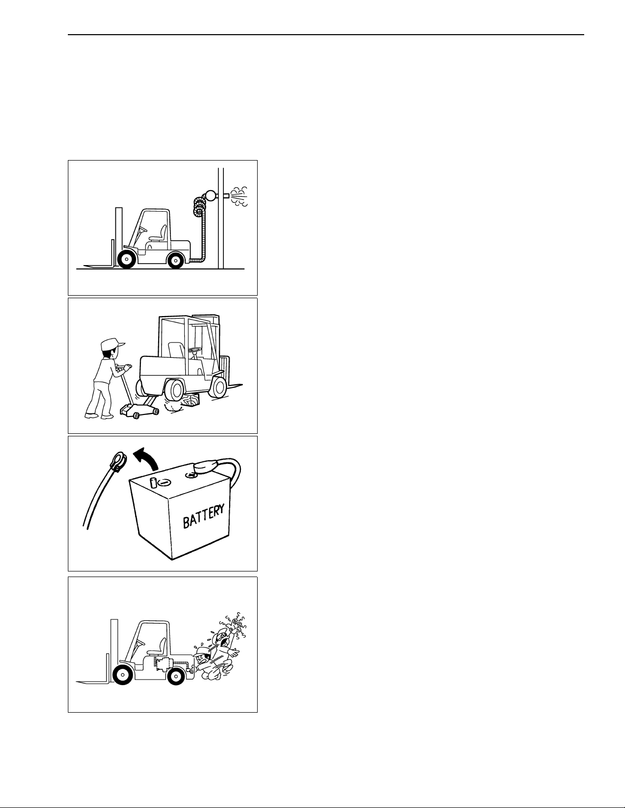
• Do not run engines inside the workshop without proper
ventilation (ex. no ventilation ducts).
• Keep the workshop well ventilated and free of any flammable
materials. Special care should be taken when flammable or
poisonous materials such as gasoline are handled.
• Discard waste oil after oil changes or parts treatment in
accordance with local laws and regulations.
• Be careful of burns and injury when working on hightemperature parts, rotating parts, or sliding portions.
• When working in a pit or enclosed area, ensure that adequate
ventilation is provided for discharging any hazardous emissions.
• Do not work underneath a vehicle supported only by a jack.
Always use rectangular lumbers at the prescribed points to
support the vehicle.
• Support it at the prescribed points and lock it in position with
safety devices before lifting the vehicle.
• When removing a heavy component such as the engine and
vehicle side, be careful the vehicle body does not become offbalance and fall.
• Do not smoke during service work.
• Do not wear any rings and necklaces when working. These
objects may cause electric short.
• Before starting repair work that requires no battery power,
always turn OFF the ignition switch, and disconnect the
negative battery cable.
GIM0059
GIM0060
• Do not touch any metal portions immediately after the engine is
stopped. Otherwise the heated metals may cause burns. Do not
attempt to remove any cooling system parts such as the
radiator cap while the engine is hot.
• To perform repair work safely and efficiently, always use
appropriate commercial service tools and specified SSTs
wherever required.
GI-3
Page 7

PRECAUTIONS FOR SAFETY AND QUALITY
Correct Operation
• Make sure that you understand the symptoms before starting
trouble diagnosis.
• Check correct installation status prior to removal or
disassembly. Make sure that they do not interfere with the
function of the parts they are applied to if matching marks are
required.
• Once they are removed, always replace parts indicated as "do
not reuse" with new ones. This includes: oil seals, gaskets,
packings, O-rings, lock washers, cotter pins, and self-locking
nuts.
• Replace inner and outer races of tapered or needle roller
bearings as a set.
• Arrange disassembled parts in order and prevent them from
being mixed-up.
• Clean or flush disassembled parts prior to inspection or
assembly.
• Use Genuine NISSAN parts for replacement.
• Use authorized grease and sealer.
• Release the pressure before disconnecting pressurized piping
or hoses.
• Be sure to check for leakage after repairing fuel, oil, coolant,
exhaust, or vacuum systems.
GI-4
Page 8

PRECAUTIONS
PRECAUTIONS
Precautions in Draining Engine Coolant
• Drain coolant only after the engine has cooled down.
Precautions for Disconnecting Fuel Piping
• Operation should be done in a place free from fire.
• After disconnecting, plug the pipe to prevent fuel from draining.
Precautions for Removing and
Disassembling
• Use correct SSTs in the specified position. Always pay attention
to safety.
• Be careful not to lose surface accuracy of mating or sliding
surfaces.
• To prevent foreign material from entering the engine, close
openings with appropriate tape as necessary.
• Arrange disassembled parts in their normal positions in order to
simplify locating the cause of damage or excessive wear and to
ensure correct reassembly.
• As a rule, nuts and bolts must be tightened in a diagonal
manner starting from an outer one. If a particular tightening
sequence is provided separately, follow the sequence.
Precautions for Inspection, Correction, and
Replacement
• Following the inspection procedure, inspect the parts
adequately and repair or replace as necessary. Perform the
same inspections even for new parts and replace them if
necessary.
Precautions for Assembly and Installation
• Always use a torque wrench when tightening bolts and nuts.
• Unless otherwise specified, tighten nuts and bolts from inside to
outside in a crisscross pattern. Tighten them gradually and
evenly in 2 to 3 steps.
• Always replace gasket, packing, oil seals, and O-rings with new
ones.
• For each part, perform adequate cleaning/washing and drying
with a dryer. In particular, ensure that the oil and coolant
passages are free from plugging and clogging.
• Remove any dirt and lint on sliding and mating surfaces. Before
assembly, apply ample amount of engine oil to sliding surfaces.
• If coolant was drained, bleed air from the system.
• After assembly, start engine and increase the engine speed,
then check coolant, fuel, oil, grease, and exhaust gas for
leakage.
GI-5
Page 9
PRECAUTIONS
Parts Requiring Angle Tightening
• When tightening the following parts, use an angle wrench
(SST).
• Cylinder head bolt
Before assembly, verify that no grease/oil and dust are present
on the cylinder head, cylinder block mounting face, and head
gasket. Then apply antirust oil or engine oil to the threads and
head bottoms of the head bolts.
Caution for Use of Power Tools
• The use of power tools such as an air runner is only allowed for
disassembly. Do not use them for assembly.
Precautions for Liquid Ggasket Application
REMOVING PARTS ATTACHED WITH LIQUID GASKET
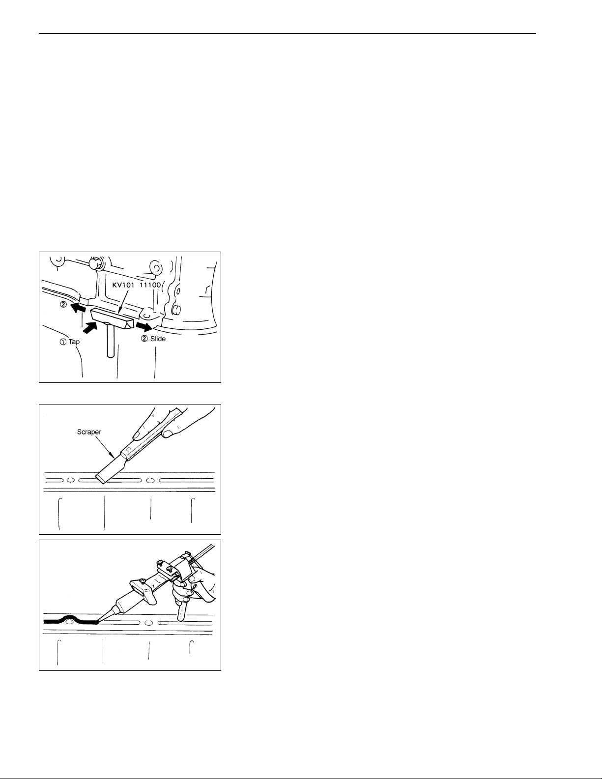
• Remove mounting nuts and bolts. Remove liquid gasket using a
seal cutter (SST).
CAUTION:
Be careful not to damage the mating surfaces.
GIM0061
GIM0062
GIM0063
• In positions where a seal cutter is difficult to use, lightly tap with
a plastic hammer, and remove.
CAUTION:
Be careful not to scratch the mating surfaces when using a
screwdriver.
LIQUID GASKET APPLICATION INSTRUCTION
1. Remove any old liquid gasket remaining on the gasket
application surface and its mating surface using a scraper.
• Remove any old liquid gasket remaining in the gasket
application groove and on the threads of bolts and bolt
holes.
2. Wipe the gasket application surface and its mating surface
using Isozole or any equivalent thinner to remove any moisture,
oil, and foreign material.
3. Set genuine liquid gasket to tube presser (commercial service
tool).
4. Apply a continuous bead of liquid gasket to the specified
position at the specified diameter.
• Apply liquid gasket in the application groove.
• Apply liquid gasket inside bolt holes as a rule. Make sure to
carefully read the relevant instructions.
• Attaching should be done within 5 minutes after gasket
application.
• Immediately wipe off any protruding liquid gasket.
• Do not retighten nuts and bolts after installation.
• After finishing work, wait at least 30 minutes before refilling
engine oil and coolant.
CAUTION:
Follow any directions specified in the text on the following
pages.
GI-6
Page 10
TIGHTENING TORQUE
TIGHTENING TORQUE
Thread size
Diameter Pitch
M6 1
M8 1.25
Hexagon head bolt and nut
M10
M6 1
M8 1.25
Flanged bolt
M10
1.25
1.5
1.25
1.5
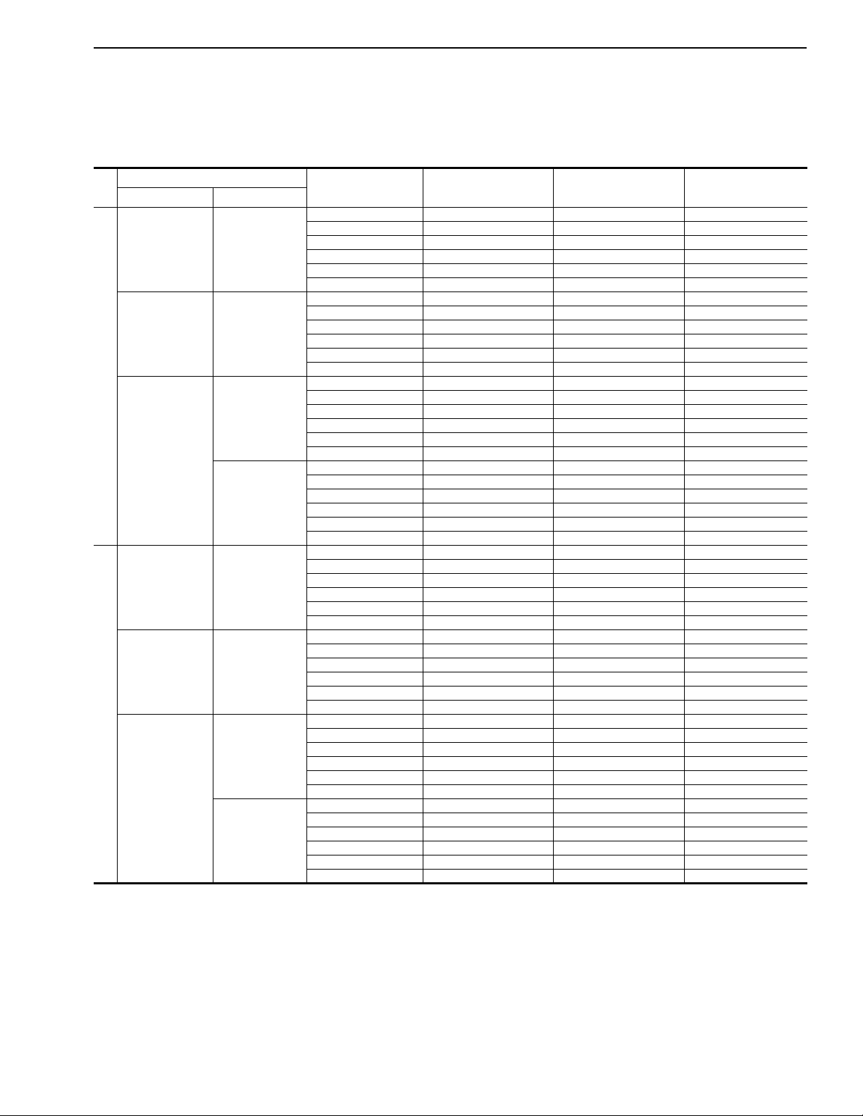
Standard Bolt Tightening Torque
Upper: Lubricated (Antirust oil is applied to abrasive faces of
threads and seating faces)
Lower: No lubrication (Threads and seating faces are
completely degreased)
Unit 4T (Bolt) 7T (Bolt) 9T (Bolt)
N·m 3.82 - 4.41 6.37 - 7.45 9.22 - 10.8
kg-m 0.39 - 0.45 0.65 - 0.76 0.94 - 1.1
ft-lb, in-lb* 34 - 39* 56 - 66* 82 - 95*
N·m 5.00 - 6.47 8.43 - 10.8 11.8 - 15.7
kg-m 0.51 - 0.66 0.86 - 1.1 1.2 - 1.6
ft-lb, in-lb* 44 - 57* 75 - 95* 9 - 12
N·m 9.32 - 10.8 15.7 - 17.7 22.6 - 25.5
kg-m 0.95 - 1.1 1.6 - 1.8 2.3 - 2.6
ft-lb, in-lb* 82 - 95* 12 - 13 17 - 19
N·m 12.7 - 15.7 20.6 - 26.5 29.4 - 37.3
kg-m 1.3 - 1.6 2.1 - 2.7 3.0 - 3.8
ft-lb, in-lb* 9 - 12 15 - 20 22 - 27
N·m 19.6 - 22.6 32.4 - 38.2 47.1 - 53.9
kg-m 2.0 - 2.3 3.3 - 3.9 4.8 - 5.5
ft-lb, in-lb* 14 - 17 24 - 28 35 - 40
N·m 25.5 - 33.3 43.1 - 54.9 61.8 - 78.5
kg-m 2.6 - 3.4 4.4 - 5.6 6.3 - 8.0
ft-lb, in-lb* 19 - 25 32 - 41 46 - 58
N·m 18.6 - 21.6 30.4 - 36.3 44.1 - 52
kg-m 1.9 - 2.2 3.1 - 3.7 4.5 - 5.3
ft-lb, in-lb* 14 - 16 22 - 27 33 - 38
N·m 24.5 - 31.4 41.2 - 52 58.8 - 74.5
kg-m 2.5 - 3.2 4.2 - 5.3 6.0 - 7.6
ft-lb, in-lb* 18 - 23 30 - 38 43 - 55
N·m 4.9 - 5.69 8.14 - 9.51 11.8 - 13.7
kg-m 0.5 - 0.58 0.83 - 0.97 1.2 - 1.4
ft-lb, in-lb* 43 - 50* 72 - 84* 9 - 10
N·m 5.98 - 7.65 9.81 - 12.7 14.7 - 18.6
kg-m 0.61 - 0.78 1.0 - 1.3 1.5 - 1.9
ft-lb, in-lb* 53 - 68* 87 - 113* 11 - 14
N·m 11.8 - 13.7 19.6 - 23.5 28.4 - 33.3
kg-m 1.2 - 1.4 2.0 - 2.4 2.9 - 3.4
ft-lb, in-lb* 9 - 10 14 - 17 21 - 25
N·m 14.7 - 18.6 24.5 - 31.4 35.3 - 45.1
kg-m 1.5 - 1.9 2.5 - 3.2 3.6 - 4.6
ft-lb, in-lb* 11 - 14 18 - 23 26 - 33
N·m 24.5 - 29.4 41.2 - 48.1 59.8 - 69.6
kg-m 2.5 - 3.0 4.2 - 4.9 6.1 - 7.1
ft-lb, in-lb* 18 - 22 30 - 35 44 - 51
N·m 30.4 - 39.2 51.0 - 64.7 73.6 - 93.2
kg-m 3.1 - 4.0 5.2 - 6.6 7.5 - 9.5
ft-lb, in-lb* 22 - 29 38 - 48 54 - 69
N·m 23.5 - 27.5 39.2 - 46.1 56.9 - 65.7
kg-m 2.4 - 2.8 4.0 - 4.7 5.8 - 6.7
ft-lb, in-lb* 17 - 20 29 - 34 42 - 48
N·m 29.4 - 37.3 49.0 - 61.8 69.6 - 89.2
kg-m 3.0 - 3.8 5.0 - 6.3 7.1 - 9.1
ft-lb, in-lb* 22 - 27 36 - 46 51 - 66
CAUTION:
• Except special nuts and bolts.
• The bolts applicable to this table have one of the following
marks embossed on their heads.
4T......4
7T......7
9T......9
GI-7
Page 11
TIGHTENING TORQUE
Standard Bolt Tightening Torque (Cont’d)
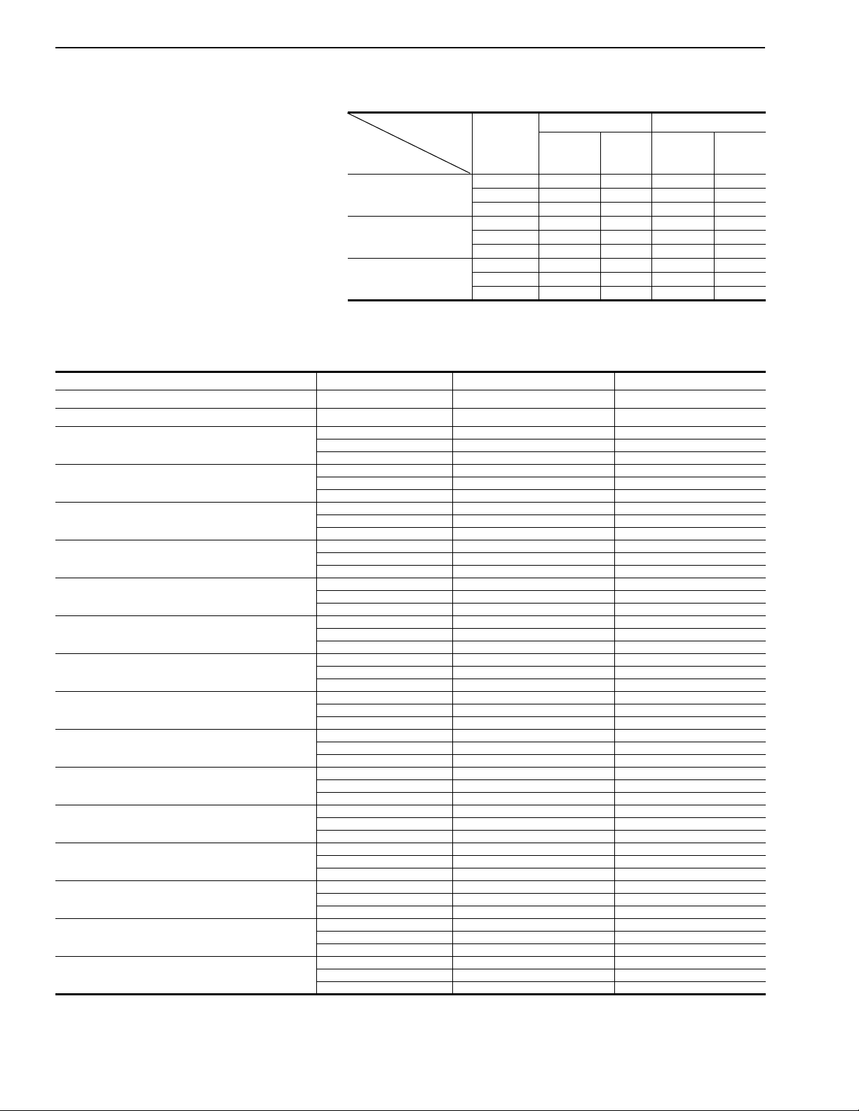
TAPER SCREW TIGHTENING TORQUE
Allowable materials
for tightening
Normal size
R1/8
R1/4
R3/8
Engine Part Tightening Torque
TIGHTENING TORQUE AT VARIOUS POINTS OF ENGINE
Tightening point Unit Standard Max. value
Cylinder head (lubricated) Separately given
Main bearing cap (lubricated) Separately given
Crankshaft pulley bolt (lubricated)
Flywheel bolt (lubricated)
Connecting rod nut (lubricated)
Rear plate bolt
Camshaft sprocket bolt
Oil filter stud
Oil filter element
Spark plug
Engine slinger bolt
Rocker cover nut
Water temperature gauge
Oil pressure switch
Exhaust manifold nut
Straight screw plug (For head top face)
Oil pan drain plug
N·m 220.5 240.1
kg-m 22.5 24.5
ft-lb, in-lb* 163 177
N·m 132 142
kg-m 13.47 14.49
ft-lb, in-lb* 94.4 104.8
N·m 31.4 37.3
kg-m 3.2 3.81
ft-lb, in-lb* 23 27.6
N·m 44.1 58.8
kg-m 4.5 6.0
ft-lb, in-lb* 33 43
N·m 39.2 49
kg-m 4.0 5.0
ft-lb, in-lb* 29 36
N·m 29.4 39.2
kg-m 3.0 4.0
ft-lb, in-lb* 22 29
N·m 14.7 20.6
kg-m 1.5 2.1
ft-lb, in-lb* 11 15
N·m 19.6 29.4
kg-m 2.0 3.0
ft-lb, in-lb* 14 22
N·m 22.6 25.5
kg-m 2.31 2.6
ft-lb, in-lb* 16.7 19
N·m 13.7 15.7
kg-m 1.4 1.6
ft-lb, in-lb* 10 12
N·m 15.7 19.6
kg-m 1.6 2.0
ft-lb, in-lb* 12 14
N·m 15.7 21.6
kg-m 1.6 2.2
ft-lb, in-lb* 12 16
N·m 41.2 48.1
kg-m 4.2 4.91
ft-lb, in-lb* 30 35.5
N·m 44.1 58.9
kg-m 4.5 5.5
ft-lb, in-lb* 33 40
N·m 29.4 39.2
kg-m 3.0 4.0
ft-lb, in-lb* 22 29
Aluminum Cast iron
Unit
N·m 7.8 11.8 15.7 21.6
kg-m 0.796 1.2 1.6 2.2
ft-lb, in-lb* 69* 9 12 16
N·m 19.6 29.4 34.3 44.1
kg-m 2.0 3.0 3.5 4.5
ft-lb, in-lb* 14 22 25 33
N·m 39.2 54.9 53.9 73.5
kg-m 4.0 5.6 5.5 7.5
ft-lb, in-lb* 29 41 40 33
Standard
Max.
value
Standard
Max.
value
GI-8
Page 12
Tightening point Unit Standard Max. value
Fuel tube flare nut
Thermo-housing air relief plug
TIGHTENING TORQUE
Engine Part Tightening Torque (Cont’d)
N·m 16.0 23.0
kg-m 1.63 2.35
ft-lb, in-lb* 11.8 17
N·m 6.37 7.45
kg-m 0.65 0.76
ft-lb, in-lb* 56* 66*
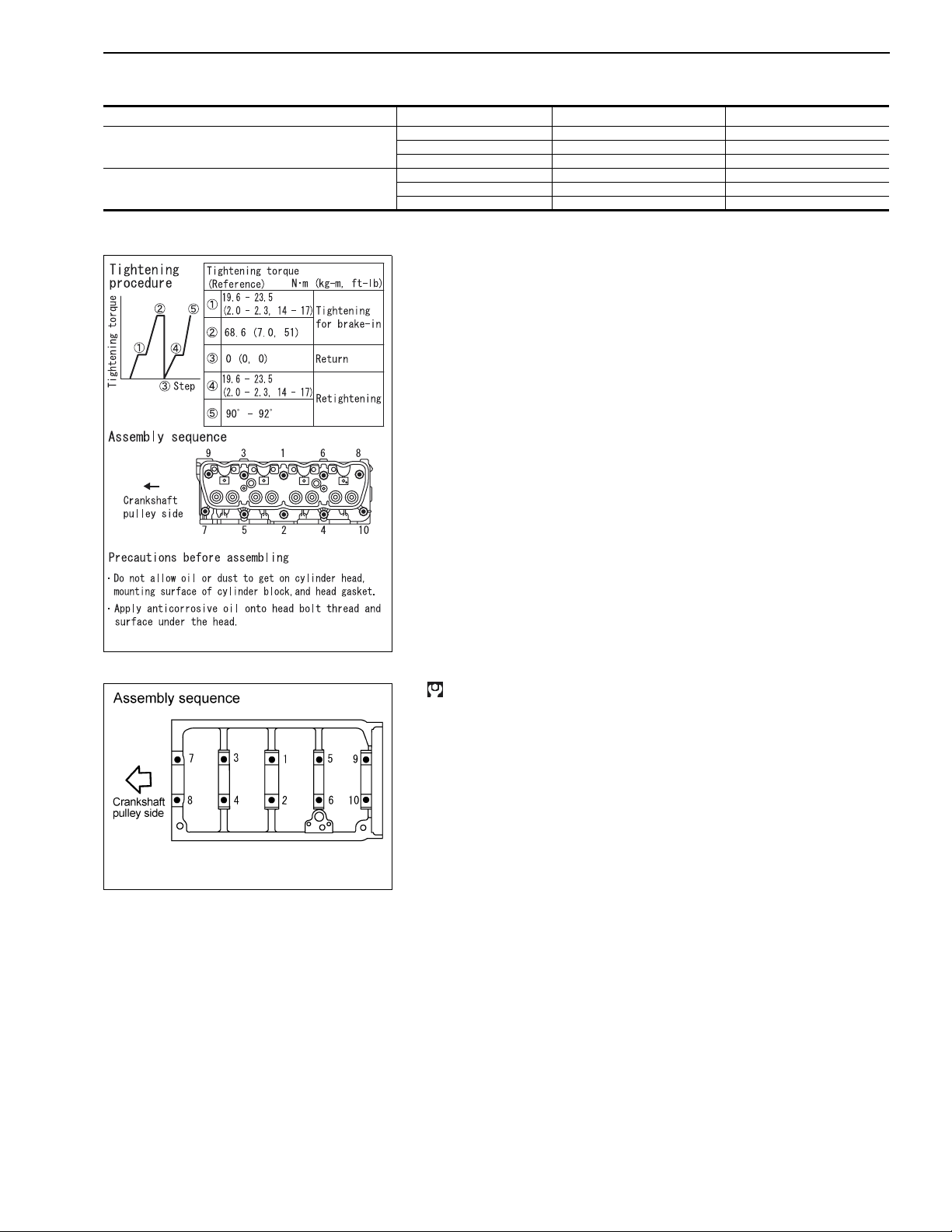
CYLINDER HEAD
Tightening torque for general service is 68.6 N·m (7.0 kg-m, 51 ft-lb)
in the place of the tightening torque (5) as shown in the figure.
MAM0147
GIM0064
MAIN BEARING CAP
: 83.4 - 93.2 N•m (8.51 - 9.51 kg-m, 61.6 - 68.8 ft-lb)
• Apply antirust oil or engine oil to the bolt threads and head
bottom.
• Do not use any power tools such as an air runner for assembly.
GI-9
Page 13

SPECIAL SERVICE TOOLS
SPECIAL SERVICE TOOLS
Tool number Tool name
KV11103000 Pulley puller Removing crankshaft pulley
GIM0065
ST05240001 Engine attachment
GIM0066
ST0501S000
(1) ST05011000
(2) ST05012000
KV101041S0
(1) KV10104110
(2) ST16512001
(3) ST16701001
Engine stand assembly
Engine stand
Stand
GIM0067
Crankshaft main bearing cap puller
Crankshaft main bearing puller
Adapter
Adapter
ST12070000 Valve lifter
ST1524S000
KV10105500
ST15243000
Front oil seal drift
Rear oil seal drift
Drift rod
GIM0068
GIM0069
GIM0071
GI-10
Page 14

ENGINE OUTSIDE DRAWINGS
ENGINE OUTSIDE DRAWINGS
MIXER SPECIFICATIONS
GIM0088
GI-11
Page 15

MAIN SPECIFICATIONS
MAIN SPECIFICATIONS
Engine type K21 K25
Engine control system Mixer Specifications
Fuel specification LPG
Total displacement (cc) 2,065 2,488
Shape of combustion chamber Bathtub
Valve mechanism OHV
Bore x stroke mm (in) 89 x 83 (3.50 x 3.27) 89 x 100 (3.50 x 3.94)
Compression ratio 8.7 8.7
Compression pressure [kPa (bar, kg/cm
Engine speed control system Pneumatic governor Pneumatic governor
Fuel in use (Note 1) At 20P At 20P
Maximum output [kW /rpm] 30.5 /2,400 35 /2,400
Maximum torque [N·m /rpm] 140 /1,600 170 /1,600
Valve opening/closing timing
(degree)
Valve clearance mm (in) Intake (when engine is hot) 0.38 (0.0150)
Firing order 1-3-4-2
Ignition timing (idling) (BTDC deg.) 2 0
On board idle speed (rpm) ATM 700 700
On board high-idle speed (rpm) ATM 3,000 2,800
Allowable maximum engine
speed (rpm)
PTO system Silent chain-driven/side PTO
Engine oil (originally fitted) Specification 10W-30 (Class SJ)
Engine dimensions (length x width x height) (Note 2) mm 707 x 560 x 720 707 x 560 x 720
2
, psi)/rpm]
Intake open (BTDC) 14
Intake close (ABDC) 30
Exhaust open (BBDC) 32
Exhaust close (ATDC) 12
Exhaust (when engine is hot) 0.38 (0.0150)
MTM 700 700
MTM 3,000 2,800
Instantaneous, no load 3,600
Continuous load 3,000
Amount 2 (Imp qt) 3.7 (3-1/4) (including oil filter)
MAIN SPECIFICATIONS
1,226 (12.2, 12.5, 178)/250 1,226 (12.2, 12.5, 178)/250
Engine weight (w/o coolant, w/ oil) (Note 2) kg (lb) 143 (315) 145 (320)
Note 1: Fuel
LPG: Use a fuel of 20P or more in cold seasons. In ambient
temperature of -5°C (23°F) or less, use a 100P fuel.
Note 2: The engine dimensions and weight differs with the
customer specifications. The above data should be
deemed as reference.
GI-12
Page 16
MAIN SPECIFICATIONS
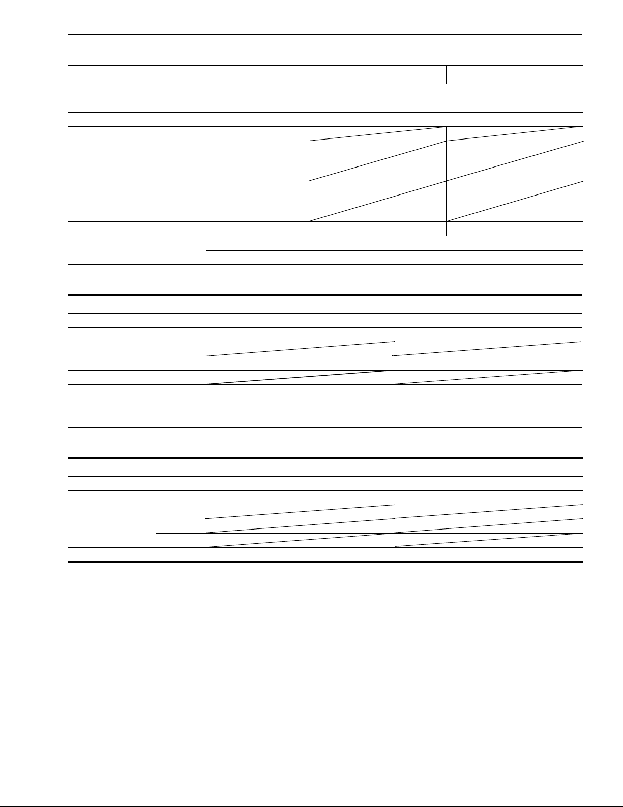
MAIN SPECIFICATIONS OF IGNITION SYSTEM
Engine type K21 K25
Engine control system Mixertype
Fuel specification LPG
Ignition device Non-contact type (Full transistor)
Ignition coil (with power transistor) Hanshin Electric type
Crankshaft position sensor
(POS)
Camshaft position sensor
(PHASE)
Crankshaft position
sensor
Distributor (with ignition coil) Mitsubishi Electric type T6T87778 T6T87779
Spark plug NGK type FR2A-D
HJ type
HJ type
Gap mm (in) 0.9 (0.035)
FUEL SYSTEM AND ENGINE SPEED CONTROL SYSTEM
Engine type K21 K25
Engine control system
Fuel specification
Fuel device standard type
Fuel device
Air-fuel ratio control device
Starting auxiliary device
Idle load control type
Engine speed control type
Mixer type
LPG
Mixer
Hot water type auto throttle
FICD
Pneumatic governor
EXHAUST GAS CLEANUP DEVICE LIST
Engine type K21 K25
Engine control system Mixer type
Fuel specification LPG
Catalytic device
(Reducing HC, CO,
Nox)
PCV gas recirculation device Closed type
Ty p e
Location
Capacity
GI-13
Page 17

STANDARD AND REPAIR LIMIT
STANDARD AND REPAIR LIMIT
INSPECTION AND ADJUSTMENT
• Oil capacity H line: 2 (Imp qt), 2 (Imp pt)*
3.7 (3-1/4)
• Oil capacityL line: 2 (Imp qt), 2 (Imp pt)*
2.7 (2-3/8)
• (Oil filter capacity): 2(Imp qt),2(Imp pt)*
0.3 (1/2)*
• Fan belt deflection [When pressed by a force of approximately
10 kg (22 lb)] : mm (in)
Standard 11 - 13 (0.45 - 0.51)
• Compression: kPa (bar, kg/cm
Standard 1.226 (12.3, 12.5, 178)/250 (K21)
1,275 (12.8, 13.0, 185)/250 (K25)
• Difference between each cylinder: kPa (bar, kg/cm
Repair limit 981 (9.8, 10, 142)/300
• Spark plug gap : mm (in)
Standard 0.8 - 0.9 (0.31 - 0.35)
• Distributor (Full transistor type) air gap : mm (in)
Standard 0.35 - 0.45 (0.0138 - 0.0177)
• Valve clearance (Hot) : mm (in)
Standard Intake: 0.38 (0.0150)
Exhaust: 0.38 (0.0150)
• Thermostat valve opening temperature (STD): °C (°F)
Standard 76.5 (170)
• Idle speed and ignition timing (BTDC°/rpm)
Standard
Mixer sp eci fic ati ons 2/70 0± 50 ( K 21 )
2
, psi)/rpm
0/700±50 (K25)
2
, psi)/rpm
CYLINDER HEAD
• Cylinder head : mm (in)
Material Aluminum alloy
Distortion limit 0.1 (0.004)
CYLINDER BLOCK
• Block upper surface : mm (in)
Distortion limit 0.1 (0.004)
• Bore diameter dimension : mm (in)
Standard 89.00 - 89.05 (3.5039 - 3.5059)
• Bore diameter wear : mm (in)
Repair limit 0.2 (0.008)
• Bore diameter out-of-round : mm (in)
Standard 0.02 (0.0008) or less
• Bore diameter taper : mm (in)
Standard 0.02 (0.0008) or less
• Bore diameter out-of-round and taper : mm (in)
Repair limit 0.1 (0.004)
GI-14
Page 18

STANDARD AND REPAIR LIMIT
PISTON
• Piston : mm (in)
Type Thermal flow type
Material Aluminum alloy
Outer diameter Standard 88.965 - 89.015
• Clearance between piston and cylinder : mm (in)
Standard 0.025 - 0.045 (0.0025 - 0.0018)
(Selective fit service parts)
• Piston pin outer diameter : mm (in)
Standard 19.993 - 19.998 (0.7871 - 0.7873)
• Piston pin fitting quality
Standard To a degree allowing movement by hand
• Piston ring end clearance : mm (in)
Standard Top 0.28 - 0.43
Second 0.45 - 0.60
Oil 0.20 - 0.60
Various limit values 1.00 mm (0.0394 in)
• Clearance between piston ring and ring groove : mm (in)
Standard Top 0.045 - 0.080
Second 0.030 - 0.070
Oil —
Repair limit Top 0.10 (0.0039)
Second 0.10 (0.0039)
Oil —
(3.5026 - 3.5045)
(0.0110 - 0.0169)
(0.0177 - 0.0236)
(0.0079 - 0.0236)
(0.0018 - 0.0031)
(0.0012 - 0.0028)
CONNECTING ROD
• Distance between both end hole centers : mm (in)
Standard 143.970 - 144.030 (5.6681 - 5.6705) (K25)
152.470 - 152.530 (6.0027 - 6.0051) (K21)
• Large end hole diameter : mm (in)
Standard 48.0 - 48.013 (1.8898 - 1.8903)
• Small end hole diameter : mm (in)
Standard 19.965 - 19.978 (0.7860 - 0.7865)
• Bend [per 100 mm (3.94 in)] : mm (in)
Repair limit 0.05 (0.0020)
• Torsion [per 100 mm (3.94 in)] : mm (in)
Repair limit 0.05 (0.0020)
• Large end thrust clearance
Standard 0.2 - 0.3 (0.008 - 0.0012)
Repair limit 0.40 (0.0157)
• Large end oil clearance : mm (in)
Standard 0.030 - 0.066 (0.0012 - 0.0026)
Repair limit 0.10 (0.0039)
• Difference of weight (Piston combination) : g (oz)
Standard 4 (0.14) or less
GI-15
Page 19

STANDARD AND REPAIR LIMIT
CRANKSHAFT
• Bend : mm (in)
Repair limit 0.05 (0.0020)
• End play : mm (in)
Standard 0.05 - 0.18 (0.0020 - 0.0071)
Repair limit 0.20 (0.0079)
• Journal dimension : mm (in)
Standard 62.942 - 62.955 (2.4780 - 2.4785)
• Pin standard dimension : mm (in)
Standard 44.961 - 44.974 (1.7701 - 1.7706)
• Journal oil clearance : mm (in)
Standard 0.020 - 0.073 (0.0080 - 0.0029)
Repair limit 0.10 (0.0039)
• Pin oil clearance : mm (in)
Standard 0.032 - 0.066 (0.0013 - 0.0026)
FLYWHEEL
• Flywheel surface swing : mm (in)
Repair limit 0.10 (0.0039)
• Ring gear surface swing : mm (in)
Repair limit 0.50 (0.0197)
• Flatness : mm (in)
Repair limit 0.30 (0.0118)
CAMSHAFT
• Bend : mm (in)
Repair limit 0.05 (0.0020)
• Camshaft height : mm (in)
Standard 36.750 - 36.800 (1.4468 - 1.5105)
(For both intake and exhaust)
Size reduction limit 36.5 (1.437)
• Journal dimension : mm (in)
Standard Front 45.434 - 45.447
(1.7887 - 1.7892)
Center 43.897 - 43.910
(1.7282 - 1.7287)
Rear 41.218 - 41.231
(1.6228 - 1.6233)
• End play : mm (in)
Standard 0.025 - 0.255 (0.0010 - 0.0100)
Repair limit 0.40 (0.0157)
• Journal oil clearance : mm (in)
Standard Front 0.025 - 0.051
(0.0010 - 0.0020)
Center 0.038 - 0.064
(0.0015 - 0.0025)
Rear 0.025 - 0.051
(0.0010 - 0.0020)
Repair limit Front 0.10 (0.0039)
Center 0.15 (0.0059)
• Journal oil clearance : mm (in)
Repair limit Rear 0.10 (0.0039)
GI-16
Page 20

STANDARD AND REPAIR LIMIT
VALVE
• Valve total length : mm (in)
Standard Intake 98.85 - 99.45
Exhaust 98.95 - 99.55
• Valve face angle
Standard Intake 45°30'
Exhaust 45°30'
• Head outer diameter : mm (in)
Standard Intake 38.0 - 38.3 (1.496 - 1.508)
Exhaust 32.0 - 32.3 (1.260 - 1.272)
• Valve stem outer diameter : mm (in)
Standard Intake 6.97 - 6.985 (0.2744 - 0.275)
Exhaust 6.945 - 6.960 (0.273 - 0.274)
• Valve guide inner diameter : mm (in)
Standard Intake 7.0 - 7.018 (0.2756 - 0.2763)
Exhaust 7.0 - 7.018 (0.2756 - 0.2763)
• Clearance between valve stem and valve guide : mm (in)
Standard Intake 0.020 - 0.053
Exhaust 0.040 - 0.073
Repair limit Intake 0.10 (0.0039)
Exhaust 0.10 (0.0039)
• Valve spring : mm (in)
Free length
Standard Intake and exhaust 45.9 (1.807)
• When opening valve is compressed mm/N (mm/kg, in/lb)
Standard Intake and exhaust 25.0/347.0 - 391.2
• When closing valve is installed mm/N (mm/kg, in/lb)
Standard Intake and exhaust 33.8/177.9 - 200.7
• Tilt : mm (in)
Repair limit Intake and exhaust 1.5 (0.0059)
• Clearance between valve lifter and lifter guide : mm (in)
Standard 0.016 - 0.052 (0.0006 - 0.0020)
• Clearance between crankshaft and flywheel : mm (in)
Standard 0 - 0.038 (0 - 0.0015)
• Clearance between rocker shaft and rocker arm : mm (in)
Standard 0.020 - 0.054 (0.0008 - 0.0021)
• Intake manifold : mm (in)
Distortion limit 0.1 (0.004)
• Exhaust manifold : mm (in)
Distortion limit 0.3 (0.012)
(3.8917 - 3.9153)
(3.8957 - 3.9193)
(0.0080 - 0.0021)
(0.0016 - 0.0029)
(25.0/35.4 - 39.9, 0.984/
78.1 - 88.0)
(33.8/18.1 - 20.5, 1.331/
39.9 - 45.2)
GI-17
Page 21
STAMPED LOCATION OF ENGINE NO.
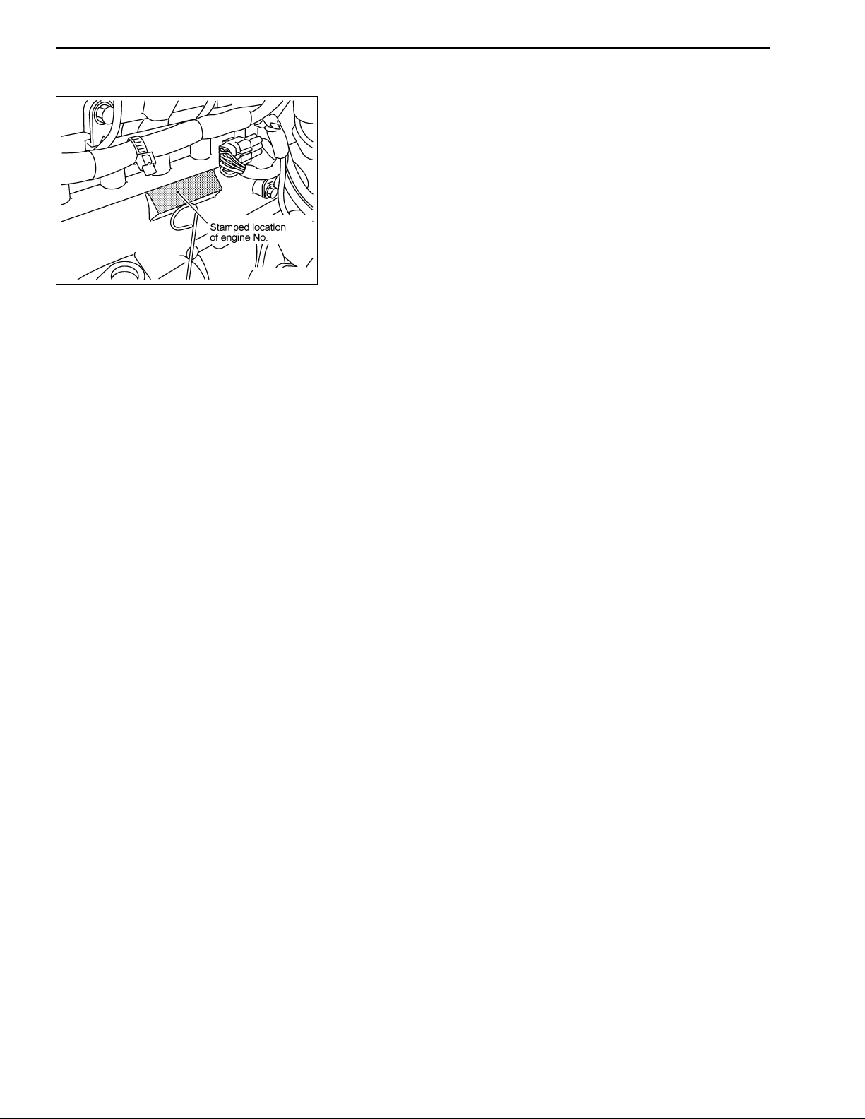
STAMPED LOCATION OF ENGINE NO.
GIM0076
GI-18
Page 22
TROUBLE DIAGNOSIS
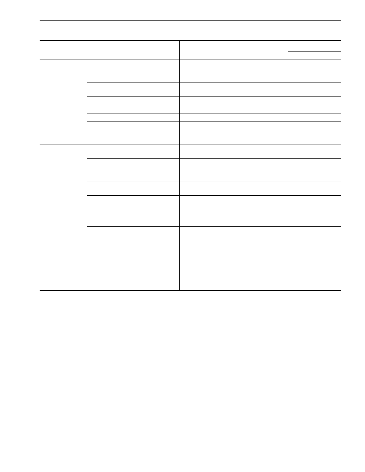
TROUBLE DIAGNOSIS
Condition Possible causes Action
Incident in ignition
system
Lowered
compression
pressure
• Malfunction of low-voltage electronic
distribution ignition coil
• Condenser malfunction Replace.
• Electric leakage from rotor cap and
rotor
• Spark plug malfunction Clean, adjust gap or replace.
• Inappropriate ignition timing Adjust.
• Ignition coil malfunction Replace.
• Open circuit in high-tension cable Replace.
• Loose or open primary wire
connection
• Poor tightening of spark plug or
inappropriate gasket
• Inappropriate engine oil grade or
deteriorated viscosity
• Inappropriate valve clearance Adjust.
• Compression pressure leak from
valve seat
• Stuck valve stem Repair or replace cylinder head and valve.
• Broken or chip valve spring Replace valve spring.
• Compression pressure leakage from
head gasket
• Worn or stuck piston ring Replace piston ring.
• Worn piston ring or cylinder Engine overhaul (Diagnosis procedure)
Refer to each section for details.
Replace.
Clean or replace.
Repair or replace.
Tighten to correct torque or replace.
Replace with appropriate grade of oil.
Remove head and perform fine grinding to valve.
Replace head gasket.
a. Put a small amount of engine oil from the
ignition plug hole and measure the
compression pressure.
b. If the pressure builds up, a possible cause is
in the cylinder or piston ring.
c. If the pressure remains unchanged, the
leakage can be attributed to the valve,
cylinder head or head gasket.
Application
Mixer specifications
○
○
○
GI-19
Page 23
TROUBLE DIAGNOSIS
Engine Adjust.
Condition Cause Action
1. Engine noise
Slapping noise of bearing and crankshaft Bearing looseness Replace.
Bearing seizure Replace.
Crankshaft bend Repair or replace.
Uneven wear of journal Correct.
Excessive end play Replace center bearing.
Slapping noise of piston, connecting rod Bearing looseness Replace.
Bearing seizure Replace.
Piston looseness Replace piston pin(s) or bushing(s).
Piston looseness relative to cylinder Reselect.
Piston ring damage Replace.
Poor rod alignment Realign.
Slapping noise of camshaft Bearing looseness Replace.
Excessive axial looseness Replace bearing thrust plate(s).
Rough gear tooth face(s) Correct.
Gear damage Replace.
Timing chain noise Inappropriate tension Adjust.
Damaged or sagged chain Replace.
Worn sprocket Replace.
Damaged or loose tensioner Replace.
Excessive camshaft-to-bearing clearance Replace.
Slapping noise of valve gear Inappropriate valve clearance Adjust.
Loose Adjust. screw(s) Replace.
Worn rocker face(s) Replace.
Worn valve guide(s) Replace guide(s).
Loose valve spring(s) Replace.
Valve seizure Repair or replace.
Slapping noise of water pump Inappropriate end play Replace.
Damaged impeller Replace.
2. Other mechanical damage
Stuck valve Inappropriate clearance Adjust.
Valve stem - insufficient guide-to-guide
clearance
Loose or damaged spring Replace.
Seized or damaged valve stem(s) Replace or clean.
Poor fuel quality Use good fuel.
Burnt valve seat(s) Inappropriate valve clearance Adjust.
Deteriorated valve spring(s) Replace.
Edged valve end(s) Replace bulb.
Too narrow valve seat width Correct valve seat(s).
Engine over temperature (Overheat) Repair or replace.
Overrun Operate in optimum speed range.
Stuck valve guide(s) Correct.
Clean stem(s), ream guide(s).
GI-20
Page 24
TROUBLE DIAGNOSIS
Engine Adjust. (Cont’d)
Condition Cause Action
Excessive wear of cylinder piston(s) Insufficient engine oil Refill or replace oil.
Contaminated engine oil Clean crankcase, replace oil filter.
Poor quality oil Use specified oil.
Engine over temperature (Overheat) Repair or replace.
Wrong combination of piston and
connecting rod
Inappropriate clearance of piston ring Reselect and adjust.
Piston ring damage Replace.
Damaged air cleaner Wash.
Too rich air-fuel mixture Adjust.
Overrun Operate in optimum speed range.
Stuck choke valve Clean and adjust.
Excessive use of choke valve Start engine properly.
Poor functioning of connecting rod(s) Insufficient engine oil Fill oil.
Low oil pressure Repair.
Use of poor quality oil Use specified oil.
Rough crank surface(s) Grind surface(s), replace bearing(s).
Plugged oil passage Clean.
Wear or damage of bearing Replace.
Inappropriate bearing Correct.
Bearing looseness Replace.
Poor connecting rod alignment Repair or replace.
Poor functioning of crankshaft bearing(s) Insufficient engine oil Fill or replace oil.
Low oil pressure Correct.
Use of poor quality oil Use specified oil.
Uneven wear of crank journal(s) Repair
Plugged oil passage of crankshaft Wash.
Wear or damage of bearing Replace.
Inappropriate bearing Correct.
Damaged bearing(s) Replace.
Repair or replace.
GI-21
Page 25
TROUBLE DIAGNOSIS
Engine Adjust. (Cont’d)
Condition Possible causes Action
No or slow cranking • Inappropriate engine oil grade Replace oil with a proper one.
• Battery is discharged Charge battery.
• Battery damage Replace battery.
• Loose fan belt Belt tension Adjust.
• Incident in charge system Check.
• Incident in starter system wiring Repair.
• Starter switch malfunction Repair or replace.
• Starter motor malfunction Repair or replace.
(Starter circuit diagnosis procedure)
If the light turns off or dims when the starter
switch is turned to "ON" with the headlights on:
a: Check the battery.
b: Check the electric connections and wirings.
c: Check the starter motor.
If the light remains bright when the starter switch
is turned to "ON" with the headlights on:
a: Check the wiring between battery and
starter motor.
b: Check the starter switch.
c: Check the starter motor.
Inappropriate idling
Lowered compression pressure Already described.
Engine power does not increase to an
appropriate level
Adjust.
Lowered compression pressure
Incident in ignition system • Inappropriate ignition timing Adjust.
• Spark plug malfunction Clean, adjust or replace.
Incident in intake system • Plugged air cleaner Replace element
• Air leakage from electronic throttle insulator Replace insulator.
• Air leakage from manifold gasket or
carburetor insulator
Engine over temperature (Overheat) • Insufficient amount of coolant Fill coolant.
• Loose fan belt. Adjust belt tension.
• Worn or loose fan belt Replace.
• Malfunctioning thermostat Replace.
• Water pump malfunction Replace.
• Plugged or leaking radiator Wash, repair, or replace.
• Radiator cap damage Replace.
• Air in cooling system piping Retighten cooling system piping, bleed system.
• Improper engine oil grade Replace with appropriate grade of engine oil.
• Inappropriate ignition timing Adjust.
• Carburetor malfunction (too lean air-fuel
mixture)
Overcool • Malfunctioning thermostat Replace.
Other • Inappropriate octane rating of fuel Replace with specified octane rating of fuel.
• Insufficient tire air pressure Charge to specified air pressure.
• Brake dragging Adjust.
• Clutch slippage Adjust.
Engine noise
Already described.
Replace gasket or insulator.
Overhaul carburetor.
GI-22
Page 26
TROUBLE DIAGNOSIS
Engine Adjust. (Cont’d)
Condition Possible causes Action
Knocking • Engine overload Operate with light load
• Knocking due to carbon deposits Remove cylinder head and eliminate carbon
deposits.
• Knocking due to inappropriate ignition timing Adjust ignition timing.
• Knocking due to inappropriate octane rating
of fuel
• Too advance ignition (Inappropriate spark
plug selection)
Mechanical slapping
Crankshaft bearing slapping • Strong and heavy noise from engine during
acceleration
• To identify the noise generation point,
attempt to cause misfires at each cylinder.
• If misfires at a particular cylinder stop the
noise, that cylinder is the noise source.
Connecting rod bearing slapping • This noise is also generated during engine
acceleration but at a little more rapid pitch
than crank slapping.
• To identify the noise generation point,
attempt to cause misfires at each cylinder.
• If misfires at a particular cylinder almost stop
the noises, that cylinder is the noise source.
Piston and cylinder slapping • Mechanical rapping noise that increases
according the engine speed but decreases
as the engine is warmed up is attributed to
the pistons and cylinders.
• To identify the noise generation point,
attempt to cause misfires at each cylinder.
Piston pin slapping • This noise is generated at piston TDC and
BDC positions.
• To identify the noise generation point,
attempt to cause misfires at each cylinder.
Water pump noise • This noise is generated from worn or
damaged bearing(s) due to the uneven
sliding faces.
Excessive oil consumption
Oil leakage • Worn piston ring groove(s) and ring(s) Replace piston(s) and piston ring(s).
• Deteriorated valve oil seal lip(s) Replace valve oil seal(s).
• Worn valve stem(s) Replace valve(s).
Other • Use of inappropriate quality of oil Use specified oil.
• Engine overheat Already described
Incident due to other factors
Low oil pressure • Use of inappropriate quality of oil Replace specified oil.
• Engine over temperature (Overheat) Already described.
• Oil pump regulator valve malfunction Overhaul or replace oil pump.
• Oil pump malfunction Overhaul or replace oil pump.
• Oil filter malfunction Replace with a new one.
• Enlarged clearance of each sliding
component
• Clogged oil strainer Wash.
• Malfunction of oil pressure gauge pressure
switch
Use specified octane rating of fuel.
Use specified type of spark plug.
A possible cause is in damage/wear of bearing or
uneven wear of crankshaft.
Need to replace bearing and adjust or replace
crankshaft.
Take the same action as that for crankshaft
bearing.
This noise is caused by excessive wear of
cylinders and accompanied by engine power
deterioration and excessive oil consumption.
For a corrective action, engine overhaul is
needed.
A possible cause is wear of the piston pin hole or
piston pin.
Need to replace piston and piston pin assembly.
Replace water pump.
Disassemble and replace relevant sliding
component(s).
Replace with a new one.
GI-23
Page 27
TROUBLE DIAGNOSIS
Engine Adjust. (Cont’d)
Condition Possible causes Action
Excessive wear of sliding part(s) • Low oil pressure Already described.
• Poor quality of oil or foreign objects in oil Replace oil element and oil with appropriate
ones.
• Poor performance of air cleaner Check element.
• Overheat or excessive cooling Already described.
• Inappropriate air-fuel ratio Check fuel system.
Bite of sliding parts • Low oil pressure Already described.
• Insufficient clearance Adjust clearance to specified value.
• Engine over temperature (Overheat) Already described.
• Inappropriate air-fuel ratio Check fuel system.
GI-24
Page 28
TROUBLE DIAGNOSIS
Engine LPG Fuel System
Condition Possible causes Action
Fuel leakage
Nasty smell • Looseness of piping connection Tighten.
• Operating malfunction of vaporizer Repair and adjust.
• Poor connection or some foreign object is
caught in between plunger rubber seat and
valve seat of solenoid valve
• Operating malfunction of lock off mechanism Adjust.
Excessive fuel consumption • Looseness of piping connection Retighten and adjust.
• Primary side room pressure at idle is
excessively high.
• Clogged air cleaner Wash.
• Adjusting malfunction of LPG mixer main
adjusting screw
Low output • Operating malfunction of vaporizer Repair and adjust.
• Looseness of piping connection or clogged
filter
• Adjusting malfunction of vaporizer primary
and secondary room pressures
• Adjusting malfunction of LPG mixer main
adjusting screw
• Use improper fuel. Use proper fuel.
• Clogged fuel passage Clean.
Inconsistent or rough idle • Improper position of vaporizer idle Adjust.
screw or carburetor throttle valve, or
operating malfunction of electric throttle
control actuator
• Operating malfunction of vaporizer Repair and adjust.
• Operating malfunction of vaporizer valve (It is
closed improperly.)
Engine hesitation or hunting • Operating malfunction of vaporizer Adjust.
• Adjusting malfunction of idle speed Adjust.
Poor starting engine • Insufficient fuel Refill fuel.
• Operating malfunction Make sure that manual valve is opened.
• Operating malfunction of solenoid valve Check and repair wiring, switch, and solenoid
• Operating malfunction of vaporizer Replace.
• Water pump malfunction Repair and adjust
• Adjusting malfunction of idle speed Adjust.
Operating malfunction of vaporizer • Adjusting malfunction of vaporizer primary
and secondary room pressures
• Leakage from primary and secondary valve
seats of vaporizer
• Damage of diaphragm Replace.
• Foreign materials enter vaporizer inside Clean and adjust.
• Leakage by looseness of setscrew Tighten.
• Overcool of vaporizer (Fur deposit, damage
of hose, poor coolant circulation)
• Tar deposit in valve Remove tar and clean.
Clean and rub.
Clean and adjust.
Adjust.
Clean and retighten.
Adjust.
Adjust.
Adjust.
Clean, adjust or replace.
valve.
Adjust.
Clean, adjust, or replace.
Check, clean, and adjust.
GI-25
Page 29
MAINTENANCE
CONTENTS
ENGINE MAINTENANCE .................................. MA-2
Specifications .................................................MA-2
Tightening Torque ..........................................MA-6
SECTION
Maintenance Schedule ................................... MA-8
Oil and Grease, and Capacity ........................MA-9
On Board Inspection and Service .................MA-10
MA
Page 30

ENGINE MAINTENANCE
ENGINE MAINTENANCE
Specifications
INSPECTION AND ADJUSTMENT
• Oil capacity H line: 2(Imp qt)
3.7 (3-1/4)
• Oil capacity L line: 2(Imp qt)
2.7 (2-3/8)
• (Oil filter capacity): 2(Imp pt)
0.3 (1/2)
• Fan belt deflection [When pressed by a force of approximately
10 kg (22 lb)] : mm (in)
Standard 11 - 13 (0.43 - 0.59)
• Compression: kPa (bar, kg/cm
Standard 1,226 (12.3, 12.5, 178)/250 (K21)
1,275 (12.7, 13.0, 185)/250 (K25)
• Difference between each cylinder: kPa (bar, kg/cm
Repair limit 98 (0.98, 1.0, 14)/300
• Spark plug gap : mm (in)
Standard 0.8 - 0.9 (0.31 - 0.35)
• Distributor (Full transistor type) air gap : mm (in)
Standard 0.35 - 0.45 (0.0138 - 0,0177)
• Valve clearance (Hot) : mm (in)
Standard Intake: 0.38 (0.0150)
Exhaust: 0.38 (0.0150)
• Thermostat valve opening temperature (STD): °C (°F)
Standard 76.5 (170)
• Idle speed and ignition timing (BTDC°/rpm)
Standard 2/700±50 (K21)
0/700±50 (K25)
2
, psi)/rpm
2
, psi)/rpm
CYLINDER HEAD
• Cylinder head : mm (in)
Material Aluminum alloy
Distortion limit 0.1 (0.004)
CYLINDER BLOCK
• Block upper surface : mm (in)
Distortion limit 0.1 (0.004)
• Bore diameter dimension : mm (in)
Standard 89.00 - 89.05 (3.5039 - 3.5059)
• Bore diameter wear : mm (in)
Repair limit 0.2 (0.008)
• Bore diameter out-of-round : mm (in)
Standard 0.02 (0.008) or less
• Bore diameter taper : mm (in)
Standard 0.02 (0.008) or less
• Bore diameter out-of-round and taper : mm (in)
Repair limit 0.1 (0.004)
MA-2
Page 31

ENGINE MAINTENANCE
Specifications (Cont’d)
PISTON
• Piston : mm (in)
Type Thermal flow type
Material Aluminum alloy
Outer diameter Standard 88.965 - 89.015
(3.5026 - 3.5045)
• Gap between piston and cylinder : mm (in)
Standard 0.025 - 0.045 (0.0010 - 0.0018)
(Selective fit service parts)
• Piston pin outer diameter : mm (in)
Standard 19.993 - 19.998 (0.7871 - 0.7873)
• Piston pin fitting quality
Standard To a degree allowing movement by hand
• Piston ring end gap : mm (in)
Standard Top 0.28 - 0.43
Second 0.45 - 0.60
Oil 0.20 - 0.60
Various limit values 1.00 (0.0394)
• Gap between piston ring and ring groove : mm (in)
Standard Top 0.045 - 0.080
Second 0.030 - 0.070
Oil 0.65 - 0.135
Repair limit Top 0.10 (0.0039)
Second 0.10 (0.0039)
Oil -
(0.0110 - 0.0169)
(0.0177 - 0.0236)
(0.0079 - 0.0236)
(0.0018 - 0.0031)
(0.0012 - 0.0028)
(0.0256 - 0.0053)
CONNECTING ROD
• Distance between both end hole centers : mm (in)
Standard 143.970 - 144.030 (5.6681 - 5.6811) (K25)
152.470 - 152.530 (6.0027 - 6.0051) (K21)
• Large end hole diameter : mm (in)
Standard 48.0 - 48.013 (1.8898 - 1.8903)
• Small end hole diameter : mm (in)
Standard 19.965 - 19.978 (0.7860 - 0.7865)
• Bend (per 100 mm) : mm (in)
Repair limit 0.05 (0.0020)
• Torsion (per 100 mm) : mm (in)
Repair limit 0.05 (0.0020)
• Large end thrust gap
Standard 0.2 - 0.3 (0.0079 - 0.0118)
Repair limit 0.40 (0.0157)
MA-3
Page 32

ENGINE MAINTENANCE
Specifications (Cont’d)
• Large end oil clearance : mm (in)
Standard 0.030 - 0.066 (0.0012 - 0.0026)
Repair limit 0.10 (0.0039)
• Difference of weight (Piston combination): g (oz)
Standard 4 (0.14) or less
CRANKSHAFT
• Bend : mm (in)
Repair limit 0.05 (0.0020)
• End play : mm (in)
Standard 0.05 - 0.18 (0.0020 - 0.0071)
Repair limit 0.20 (0.0079)
• Journal dimension : mm (in)
Standard 62.942 - 62.955 (2.4780 - 2.4785)
• Pin standard dimension : mm (in)
St an da rd 44 .9 61 - 44 .9 74 ( 1. 770 1 - 1.7 70 6)
• Journal oil clearance : mm (in)
Standard 0.020 - 0.073 (0.0008 - 0.0029)
Repair limit 0.10 (0.0039)
• Pin oil clearance : mm (in)
Standard 0.032 - 0.066 (0.0013 - 0.0026)
FLYWHEEL
• Flywheel surface swing : mm (in)
Repair limit 0.10 (0.0039)
• Ring gear surface swing : mm (in)
Repair limit 0.50 (0.0197)
• Flatness : mm (in)
Repair limit 0.30 (0.0118)
CAMSHAFT
• Bend : mm (in)
Repair limit 0.05 (0.0020)
• Camshaft height : mm (in)
Standard 36.750 - 36.800 (1.4468 - 1.4488)
(For both intake and exhaust)
Size reduction limit 36.5 (1.437)
• Journal dimension : mm (in)
Standard Front 45.434 - 45.447 (1.7887 - 1.7892)
Center 43.897 - 43.910 (1.7318 - 1.7287)
Rear 41.218 - 41.231 (1.6228 - 1.6233)
• End play : mm (in)
Standard 0.025 - 0.255 (0.0010 - 0.0100)
Repair limit 0.40 (0.0157)
• Journal oil clearance : mm (in)
Standard Front 0.025 - 0.051 (0.0010 - 0.0020)
Center 0.038 - 0.064 (0.0015 - 0.0025)
Rear 0.025 - 0.051 (0.0010 - 0.0020)
Repair limit Front 0.10 (0.0039)
Center 0.15 (0.0059)
• Journal oil clearance : mm (in)
Repair limit Rear 0.10 (0.0039)
MA-4
Page 33

ENGINE MAINTENANCE
Specifications (Cont’d)
VALVE
• Head outer diameter : mm (in)
Standard Intake 38.0 - 38.3 (1.496 - 1.508)
Exhaust 32.0 - 32.3 (1.260 - 1.272)
• Valve stem outer diameter : mm (in)
Standard Intake 6.97 - 6.985
Exhaust 6.945 - 6.960
• Valve guide inner diameter : mm (in)
Standard Intake 7.0 - 7.018 (0.2756 - 0.2763)
Exhaust 7.0 - 7.018 (0.2756 - 0.2763)
• Gap between valve stem and valve guide : mm (in)
Standard Intake 0.020 - 0.053
Exhaust 0.040 - 0.073
Repair limit Intake 0.10 (0.0039)
Exhaust 0.10 (0.0039)
• Gap between valve lifter and lifter guide : mm (in)
Standard 0.016 - 0.052 (0.0006 - 0.0020)
• Gap between crankshaft and flywheel : mm (in)
Standard 0 - 0.038 (0 - 0.0015)
• Gap between rocker shaft and rocker arm : mm (in)
Standard 0.020 - 0.054 (0.0008 - 0.0021)
• Valve clearance (Hot) : mm (in)
Intake 0.38±0.03 (0.0150±0.0012)
Exhaust 0.38±0.03 (0.0150±0.0012)
(0.2744 - 0.2750)
(0.2734 - 0.2740)
(0.0008 - 0.0021)
(0.0016 - 0.0029)
MA-5
Page 34
ENGINE MAINTENANCE
Tightening Torque
Upper: Lubricated (Antirust oil is applied to abrasive faces of
threads and seating faces)
Lower: No lubrication (Threads and seating faces are
completely degreased)
Thread size
Diameter Pitch
M6 1
M8 1.25
Hexagon head bolt and nut
M10
M6 1
M8 1.25
Flanged bolt
M10
1.25
1.5
1.25
1.5
Unit 4T (Bolt) 7T (Bolt) 9T (Bolt)
N·m 3.8 - 4.4 6.4 - 7.5 9.2 - 10.8
kg-m 0.39 - 0.45 0.65 - 0.76 0.94 - 1.1
ft-lb, in-lb* 34 - 39* 56 - 66* 82 - 95*
N·m 5.0 - 6.5 8.4 - 10.8 11.8 - 15.7
kg-m 0.51 - 0.66 0.86 - 1.1 1.2 - 1.6
ft-lb, in-lb* 44 - 57* 75 - 95* 9 - 12
N·m 9.3 - 10.8 15.7 - 17.7 22.6 - 25.5
kg-m 0.95 - 1.1 1.6 - 1.8 2.3 - 2.6
ft-lb, in-lb* 82 - 95* 12 - 13 17 - 19
N·m 12.7 - 15.7 20.6 - 26.5 29.4 - 37.3
kg-m 1.3 - 1.6 2.1 - 2.7 3.0 - 3.8
ft-lb, in-lb* 9 - 12 15 - 20 22 - 19
N·m 19.6 - 22.6 32.4 - 38.2 47.1 - 53.9
kg-m 2.0 - 2.3 3.3 - 3.9 4.8 - 5.5
ft-lb, in-lb* 14 - 17 24 - 28 35 - 40
N·m 25.5 - 33.3 43.1 - 54.9 61.8 - 78.5
kg-m 2.6 - 3.4 4.4 - 5.6 6.3 - 8.0
ft-lb, in-lb* 19 - 25 32 - 41 46 - 58
N·m 18.6 - 21.6 30.4 - 36.3 44.1 - 52
kg-m 1.9 - 2.2 3.1 - 3.7 4.5 - 5.3
ft-lb, in-lb* 14 - 16 22 - 27 33 - 38
N·m 24.5 - 31.4 41.2 - 52 58.8 - 74.5
kg-m 2.5 - 3.2 4.2 - 5.3 6.0 - 7.6
ft-lb, in-lb* 18 - 23 30 - 38 43 - 55
N·m 4.9 - 5.69 8.14 - 9.51 11.8 - 13.7
kg-m 0.5 - 0.58 0.83 - 0.97 1.2 - 1.4
ft-lb, in-lb* 43 - 50* 72 - 84* 9 - 10
N·m 5.98 - 7.65 9.81 - 12.7 14.7 - 18.6
kg-m 0.61 - 0.78 1.0 - 1.3 1.5 - 1.9
ft-lb, in-lb* 53 - 68* 87 - 113* 11 - 14
N·m 11.8 - 13.7 19.6 - 23.5 28.4 - 33.3
kg-m 1.2 - 1.4 2.0 - 2.4 2.9 - 3.4
ft-lb, in-lb* 9 - 10 14 - 17 21 - 22
N·m 14.7 - 18.6 24.5 - 31.4 35.3 - 45.1
kg-m 1.5 - 1.9 2.5 - 3.2 3.6 - 4.6
ft-lb, in-lb* 11 - 14 18 - 23 26 - 33
N·m 24.5 - 29.4 41.2 - 48.1 59.8 - 69.6
kg-m 2.5 - 3.0 4.2 - 4.9 6.1 - 7.1
ft-lb, in-lb* 18 - 22 30 - 35 44 - 51
N·m 30.4 - 39.2 51.0 - 64.7 73.6 - 93.2
kg-m 3.1 - 4.0 5.2 - 6.6 7.5 - 9.5
ft-lb, in-lb* 22 - 29 38 - 48 54 - 69
N·m 23.5 - 27.5 39.2 - 46.1 56.9 - 65.7
kg-m 2.4 - 2.8 4.0 - 4.7 5.8 - 6.7
ft-lb, in-lb* 17 - 20 29 - 34 42 - 48
N·m 29.4 - 37.3 49.0 - 61.8 69.6 - 89.2
kg-m 3.0 - 3.8 5.0 - 6.3 7.1 - 9.1
ft-lb, in-lb* 22 - 27 36 - 46 51 - 48
CAUTION:
Except special nuts and bolts.
The bolts applicable to this table have one of the following marks
embossed on their heads.
4T......4
7T......7
9T......9
MA-6
Page 35
ENGINE MAINTENANCE
Tightening Torque (Cont’d)
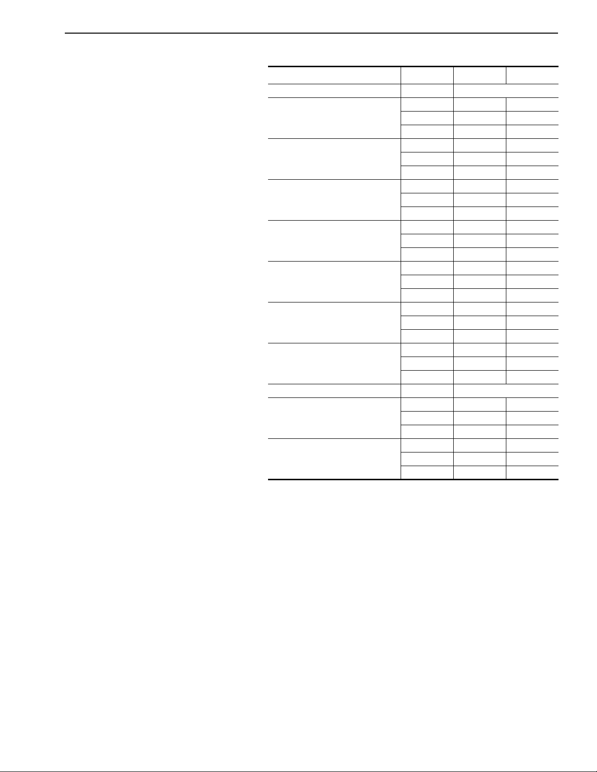
Tightening point Unit Standard Max. value
Cylinder head (lubricated) Refer to MA-10.
Crankshaft pulley bolt (lubricated) N·m 220.5 240.1
Oil filter element N·m 14.7 20.6
Spark plug N·m 19.6 29.4
Engine slinger bolt N·m 22.6 25.5
Rocker cover nut N·m 13.7 15.7
Water temperature gauge N·m 15.7 19.6
Oil pressure switch N·m 15.7 21.6
Exhaust manifold nut Refer to MA-10.
Oil pan drain plug N·m 29.4 39.2
Thermo-housing air relief plug N·m 6.37 7.45
kg-m 22.5 24.5
ft-lb, in-lb* 163 177
kg-m 1.5 2.1
ft-lb, in-lb* 11 15
kg-m 2.0 3.0
ft-lb, in-lb* 14 22
kg-m 2.31 2.6
ft-lb, in-lb* 16.7 19
kg-m 1.4 1.6
ft-lb, in-lb* 10 12
kg-m 1.6 2.0
ft-lb, in-lb* 12 14
kg-m 1.6 2.2
ft-lb, in-lb* 12 16
kg-m 3.0 4.0
ft-lb, in-lb* 22 29
kg-m 0.65 0.76
ft-lb, in-lb* 56* 66*
MA-7
Page 36
ENGINE MAINTENANCE
Maintenance Schedule
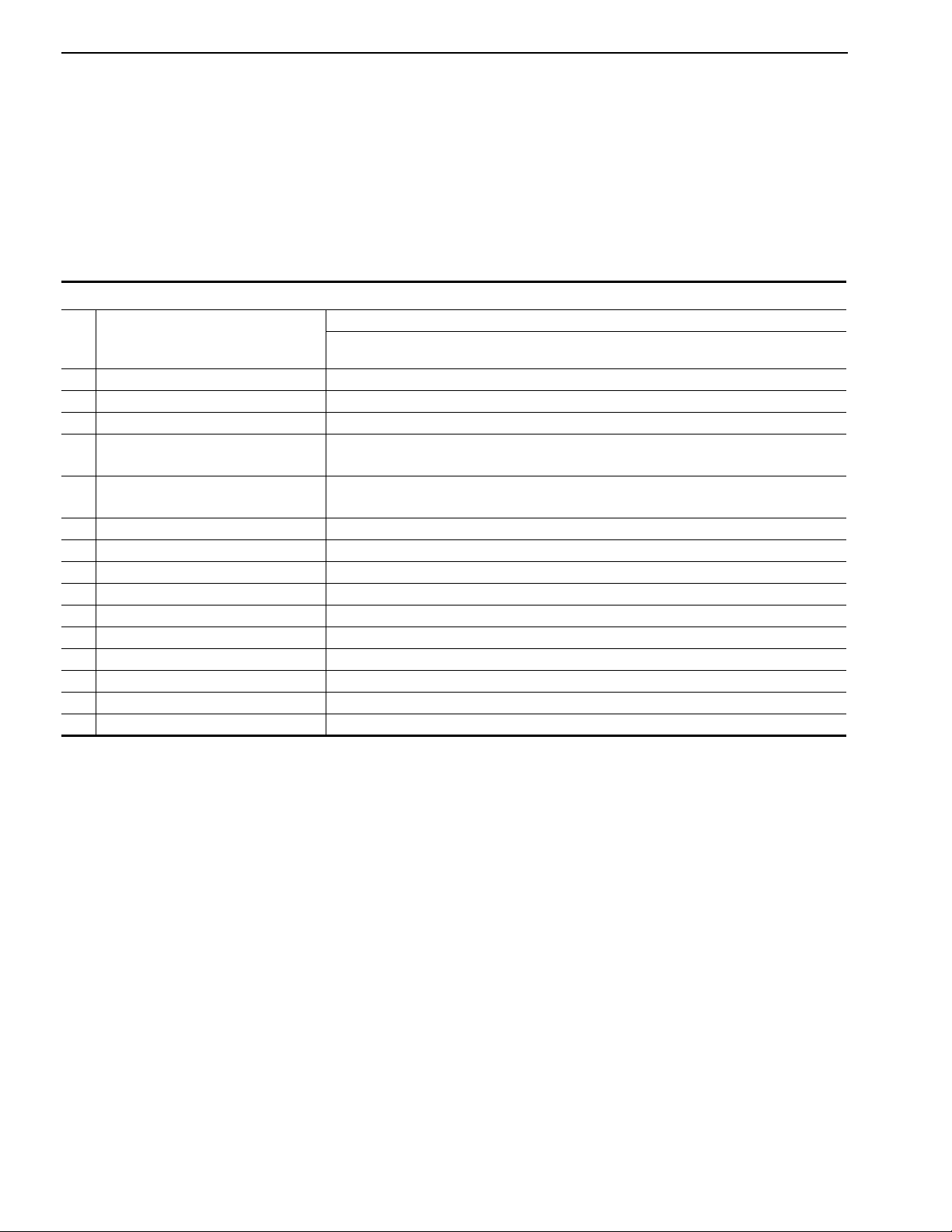
Make sure to perform appropriate maintenance and service work to
maintain the initial performances of the NISSAN forklift.
PERFORM INSPECTION
Make sure to perform the periodical inspections at appropriate
times, according to the month basis or the operating hour basis,
whichever comes first. ...... Inspection period
Refer to the following notes for values in ( )
Engine system inspection
Inspection items
No.
1 Intake/exhaust valve clearance A A A A A
2Engine drive belt tension IIIIIIIIIIII
3 Cylinder head bolt and manifold nut T
4 Engine oil (1)
Months of use 123456789101112
Operation hours
(x 100 hours)
2 4 6 8 1012141618202224
R
´ R´ R´ R´ R´
5 Oil filter (1)
6 Engine coolant R
7Fuel filter (1)CCCCR
8 Air cleaner element CCCCCRCCCCCR
9 Engine idle speed AAAAAAAAAAAA
10Ignition timing AAAAAAAAAAAA
11Spark plug IIIIIIIIIIII
12 Distributor (point, cap, and rotor) IIIIIIIIIIII
13 Distributor (inside) (1) C
14 PCV valve (1) I I I I
15 PCV hose I I I I
´ R´ R´ R´ R´
R
MA-8
Page 37
ENGINE MAINTENANCE
Maintenance Schedule (Cont’d)
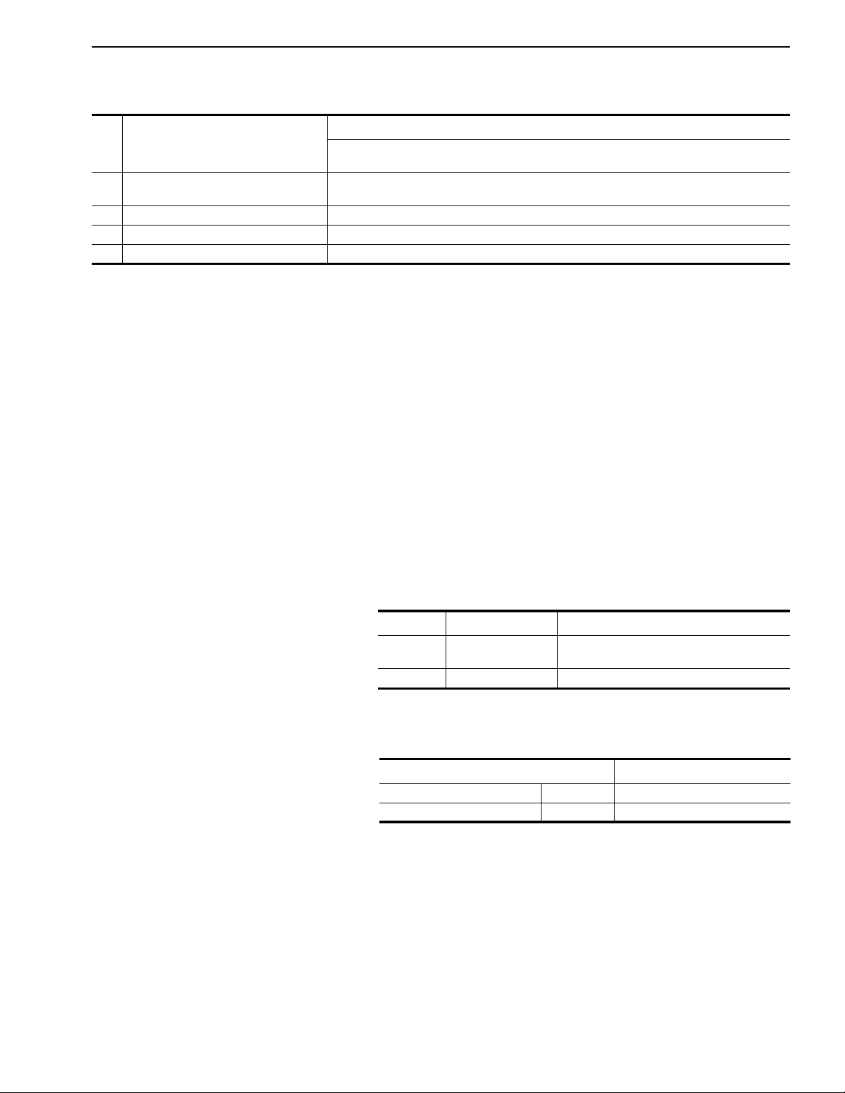
Engine system inspection
Months of use 123456789101112
No. Inspection items
1 Gas leakage from piping and piping
joints
2 Damage to piping and piping joints IIIIIIIIIIII
3 Tar in vaporizer D D D DDDDDDDDD
4 LPG filter C C C R
Operation hours
(x 100 hours)
(2) IIIIIIIIIIII
24681012141618202224
CAUTION:
• (1) The maintenance work should be performed more
frequently if the vehicle is being used in dusty and dirty
environments.
• (2) Apply soap suds to the piping joints to check for any
gas leakage after replacing the LPG tank.
Meanings of symbols:
I = Inspection. Repair or replace if necessary.
R = Replacement
A = Adjustment
C = Cleaning
D = Draining
T = Tightening (Retightening)
R' = Replacement [Every 500 hours
(3 months)] Engine oil, oil filter
Oil and Grease, and Capacity
OIL, LLC
Items Specification Remarks
Engine oil *10W-30 (Class SJ) Refer to SAE viscosity index. (SE, SH can be
Antifreeze Genuine NISSAN long life coolant
* It is the oil for filling in at factory.
FILLING CAPACITY (GUIDELINE)
Items Capacity
Engine oil K21 3.7 (3-1/4) (including filter)
used.)
Unit: 2(Imp qt)
K25 3.7 (3-1/4) (including filter)
MA-9
Page 38

ENGINE MAINTENANCE
On Board Inspection and Service
TIGHTENING OF HEAD BOLT
Tighten head bolts from inside to outside as shown in the figure.
Tighten bolts gradually as shown in the figure.
Tightening torque: 68.6 N·m (7.0 kg-m, 51 ft-lb) (This tightening
torque can be used in step (5) as shown in the figure for service.)
CAUTION:
Check tightening angle with an angle wrench (SST) or a
protractor. Do not simply estimate tightening angle.
MAM0147
RETIGHTENING OF MANIFOLD NUT AND BOLT
CAUTION:
Do not retighten nut and bolt until manifold components get
cold. It may cause to get burned.
Tightening torque for manifold and nut
Models N·m kg-m ft-lb
K21 41.2 - 48.1 4.2 - 4.91 30.4 - 35.5
K25 41.2 - 48.1 4.2 - 4.91 30.4 - 35.5
(Do not use power tools such as air runner to tighten.)
INTAKE/EXHAUST VALVE CLEARANCE ADJUSTMENT
• Adjustment must be made with the vehicle in hot condition.
1. Warm up engine until engine coolant temperature gauge shows
nearly center, and then stop it.
2. Remove rocker cover.
3. Turn the crankshaft.
CAUTION:
Disconnect high-tension cable from ignition coil when rotating
crankshaft with starter motor.
MA-10
Page 39
ENGINE MAINTENANCE
On Board Inspection and Service (Cont’d)
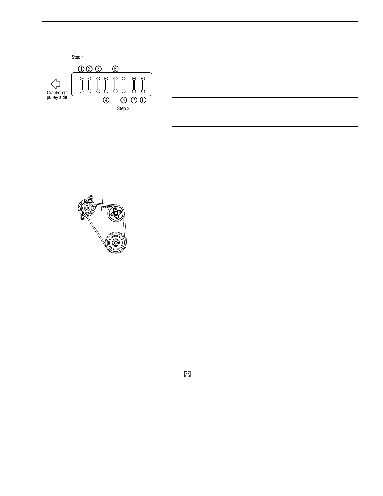
4. Set the piston for the No. 1 cylinder to the compression TDC
and adjust the valves of (1), (2), (3), and (5) in the figure.
5. Set the piston for the No. 4 cylinder to the compression TDC by
rotating crank again and adjust the valves of (4), (6), (7), and (8)
in the figure.
MAM0143
MAM0148
Intake/exhaust valve clearance (Hot)
Models Intake Exhaust
K21 0.38 (0.015) 0.38 (0.015)
K25 0.38 (0.015) 0.38 (0.015)
Unit: mm (in)
INSPECTION AND ADJUSTMENT OF ENGINE DRIVE BELT
CAUTION:
Make sure that engine stops. Wash hands.
1. Visually check fan belt for wear, damage, and cracks. Do not
contact the belt with pulley groove bottom.
2. Push the belt between pulleys. Check tension.
Belt deflection: 11 - 13 mm (0.43 - 0.51 in)
Force: 98 N (10 kg, 22 lb)
REPLACEMENT OF OIL AND OIL FILTER
1. Warm engine.
2. Remove oil pan drain plug and oil filler cap, and discharge all
oil.
CAUTION:
• Be careful not to get burned when engine or engine oil is
heated.
• It shows the mixing of coolant so that oil looks likes milk.
Repair if necessary.
• It shows the mixing of gasoline so that oil viscosity is too
lean. Repair if necessary.
3. Wipe around drain hole. Install drain plug.
Tightening torque for oil pan drain plug:
29.4 - 39.2 N·m (3.0 - 4.0 kg-m, 22 - 29 ft-lb)
MA-11
Page 40
ENGINE MAINTENANCE
On Board Inspection and Service (Cont’d)
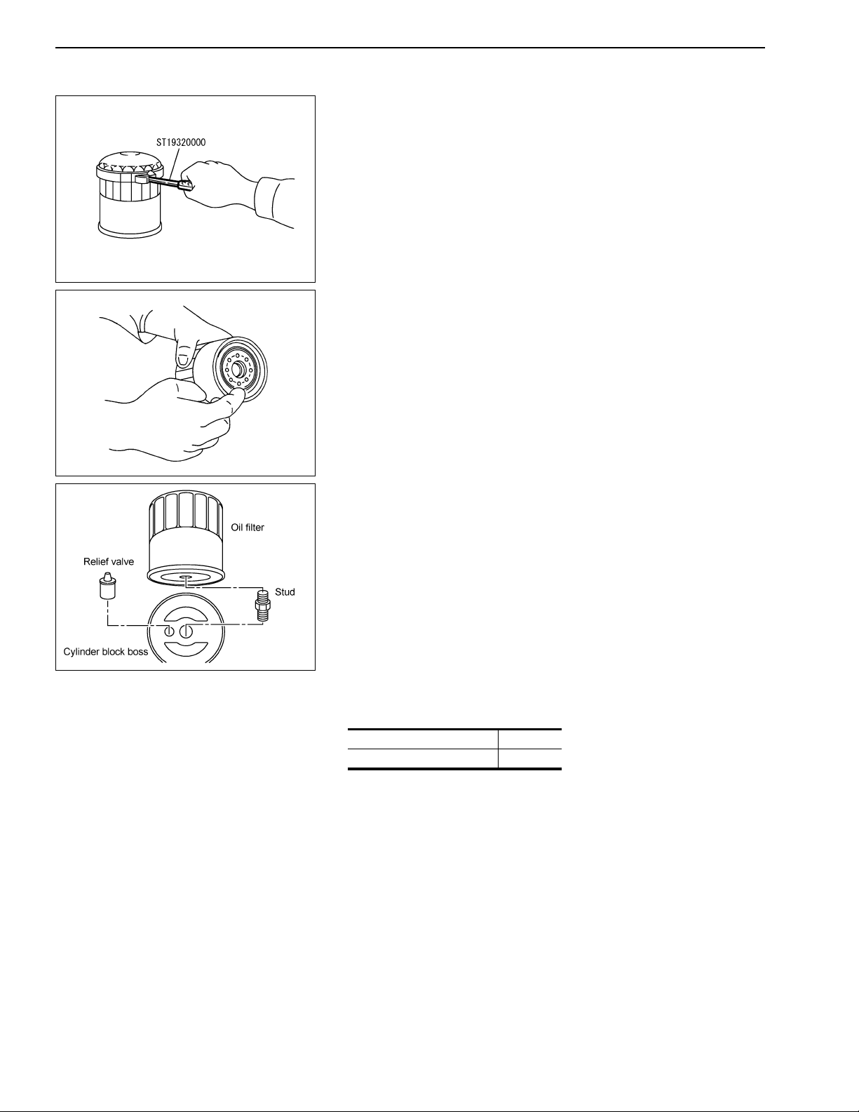
4. Replace oil filter.
• Remove oil filter using an oil filter wrench (SST).
• Wipe oil filter mounting surface with a clean shop cloth.
MAM0144
• Apply a small amount of engine oil to the lip of the new oil filter.
MAM0145
MAM0146
• Screw in the oil filter by hand until it contacts cylinder block
boss, and then screw in another 2/3 of a turn.
5. Fill the oil according to the specified lubricant amount.
Standard oil amount
Including filter 3.7 (3-1/4)
Not including filter 3.4 (3)
Unit: 2 (Imp qt)
6. Start engine, and make sure that there is no leakage around
drain plug and oil filter. Replace drain plug and oil filter if there is
some leakage.
7. Run engine, and stop it after engine coolant temperature gauge
is in nearly center position. Check oil level after waiting for a few
minutes. Refill oil if necessary.
MA-12
Page 41
ENGINE TUNE-UP
CONTENTS
SPECIFICATIONS .............................................. ET-2
TIGHTENING TORQUE ...................................... ET-3
TROUBLE DIAGNOSIS ...................................... ET-4
SECTION
ENGINE INSPECTION AND ADJUSTMENT ......ET-8
Engine Body Related ......................................ET-8
Ignition and Fuel Systems .............................ET-12
SPECIAL SERVICE TOOLS FOR CARBURETOR
MODEL ..............................................................ET-19
ET
Page 42
SPECIFICATIONS
SPECIFICATIONS
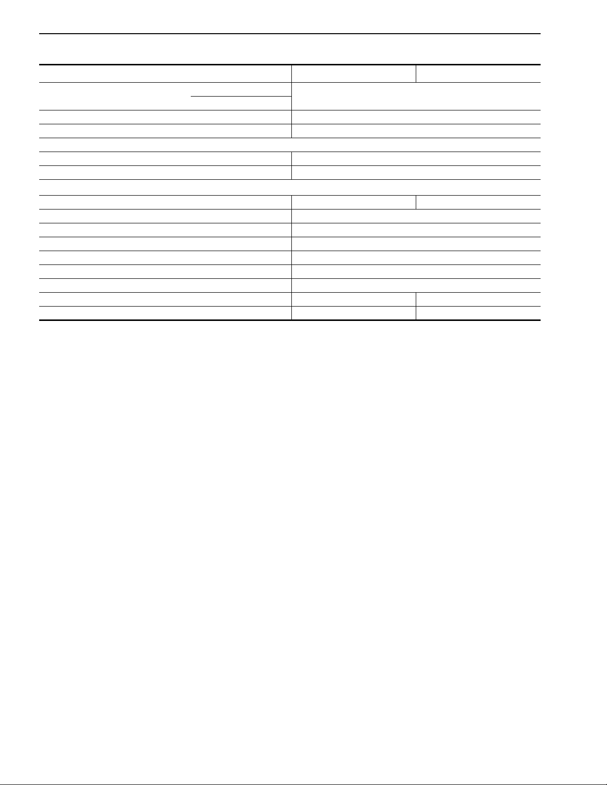
Items Engine type K21 K25
Valve clearance (Hot) mm (in)
Fan belt deflection mm (in) 11 - 13 (0.43 - 0.51)
Belt push force N (kg, lb) 98 (10, 22)
Engine oil amount L (lmp qt)
(including oil filter) 3.7 (3-1/4)
(not including oil filter) 3.4 (3-1/8)
Compression pressure
Standard 1,226 (12.26, 12.5, 178)/250 1,275 (12.75, 13.0, 185)/180
Minimum value
Spark plug type FR2A-D
Plug gap mm (in) 0.9 (0.035)
Distributor gap mm (in) 0.35 - 0.45 (0.0138 - 0.0177)
High-tension cable resistance Ω 30,000 or less
Ignition timing/idle speed BTDC deg./rpm 700±50
Maximum engine speed without load rpm (instantaneous) 3,000 2,8
Maximum engine speed with load rpm 2,750 2,60
Intake
Exhaust
kPa (bar, kg/cm
2
, psi)/rpm
0.38 (0.015)
00
0
ET-2
Page 43
TIGHTENING TORQUE
TIGHTENING TORQUE
Unit : N·m (kgf-m, ft-lb)
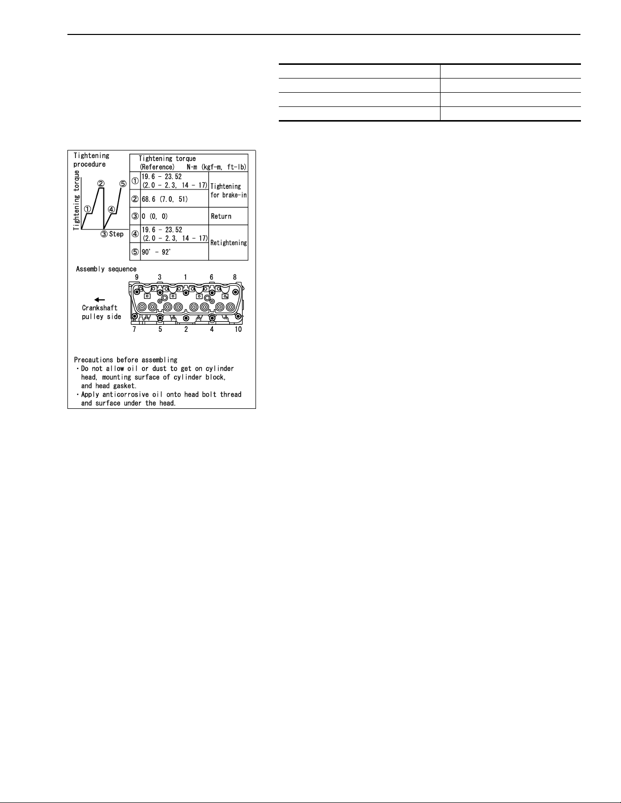
Cylinder head bolt See the figure on the left
Manifold nut 41.2 - 48.1 (4.2 - 4.91, 30.4 - 35.5)
Oil pan drain plug 29.4 - 39.2 (3.0 - 4.0, 22 - 29)
Spark plug 19.6 - 29.9 (2.0 - 3.0, 14 - 22)
CYLINDER HEAD
Tightening torque for general service is 68.6 N·m (7.0 kg-m, 51 ft-lb)
in the location of the tightening torque (5) as shown in the figure.
Apply antirust oil or engine oil to the threads and head bottom of
each head bolt.
MAM0149
ET-3
Page 44
TROUBLE DIAGNOSIS
TROUBLE DIAGNOSIS
Condition Possible causes Action
No or slow cranking • Inappropriate engine oil grade Replace oil with a proper one.
• Battery is discharged Charge battery.
• Battery damage Replace battery.
• Loose fan belt Belt tension adjustment
• Incident in charge system Inspection
• Incident in starter system wiring Repair
• Starter switch malfunction Repair or replace
• Starter motor malfunction Repair or replace
(Starter circuit diagnosis procedure)
If the light turns off or dims when the starter switch
is turned to "ON" with the headlights on:
a: Inspect the battery
b: Inspect the electric connections and wirings
c: Inspect the starter motor
If the light remains bright when the starter switch is
turned to "ON" with the headlights on:
a: Inspect the wiring between battery and
starter motor
b: Inspect the starter switch
c: Inspect the starter motor
ET-4
Page 45
TROUBLE DIAGNOSIS
Condition Possible causes Action
Incident in ignition system • Malfunction of low-voltage
electronic distribution ignition
coil
• Condenser malfunction Replace
• Electric leakage from rotor
cap and rotor
• Spark plug malfunction Clean, adjust gap or replace
• Inappropriate ignition timing Adjustment √
• Ignition coil malfunction Replace
• Open circuit in high-tension
cable
• Loose or open primary wire
connection
Lowered compression
pressure
• Poor tightening of spark plug
or inappropriate gasket
• Inappropriate engine oil grade
or deteriorated viscosity
• Inappropriate valve clearance Adjustment
• Compression pressure
leakage from valve seat
• Stuck valve stem Repair or replace cylinder head and valve.
• Broken or chip valve spring Replace valve spring.
• Compression pressure
leakage from head gasket
• Worn or stuck piston ring Replace piston ring.
• Worn piston ring or cylinder Engine overhaul (Diagnosis procedure)
Replace
Clean or replace √
Replace √
Repair or replace
Tighten to correct torque or replace
Replace with appropriate grade of oil
Remove head and perform fine grinding to valve
Replace head gasket.
a. Put a small amount of engine oil from the ignition
plug hole and measure the compression
pressure.
b. If the pressure builds up, a possible cause is in
the cylinder or piston ring.
c. If the pressure remains unchanged, the leakage
can be attributed to the valve, cylinder head or
head gasket.
Application
Mixer specifications
ET-5
Page 46
TROUBLE DIAGNOSIS
TROUBLE DIAGNOSIS
Condition Possible causes Action
Inappropriate idling
Lowered compression pressure Already described
Engine power does not increase to an
appropriate level
Adjustment
Lowered compression pressure
Incident in ignition system • Inappropriate ignition timing Adjustment
• Spark plug malfunction Clean, adjust or replace.
Incident in intake system • Plugged air cleaner Replace element
• Air leakage from electronic throttle
insulator
• Air leakage from manifold gasket or
carburetor insulator
Engine over temperature (Overheat) • Insufficient amount of coolant Fill coolant.
• Loose fan belt. Belt tension adjustment
• Worn or loose fan belt Replacement
• Malfunctioning thermostat Replacement
• Water pump malfunction Replacement
• Plugged or leaking radiator Wash, repair, or replace
• Radiator cap damage Replacement
• Air in cooling system piping Retighten cooling system piping, bleed
• Improper engine oil grade Replace with appropriate grade of engine oil.
• Inappropriate ignition timing Adjust.
• Carburetor malfunction (too lean air-fuel
mixture)
Overcool Malfunctioning thermostat Replacement
Other • Inappropriate octane rating of fuel Replace with specified octane rating of fuel.
• Insufficient tire air pressure Charge to specified air pressure.
• Brake dragging Adjustment
• Clutch slippage Adjustment
Engine noise
Knocking • Engine overload Operation with light load
• Knocking due to carbon deposits Remove cylinder head and eliminate carbon
• Knocking due to inappropriate ignition
timing
• Knocking due to inappropriate octane
rating of fuel
• Too advance ignition (Inappropriate spark
plug selection)
Mechanical slapping
Crankshaft bearing slapping • Strong and heavy noise from engine
during acceleration
• To identify the noise generation point,
attempt to cause misfires at each
cylinder.
• If misfires at a particular cylinder stop the
noise, that cylinder is the noise source.
Already described
Replace insulator.
Replace gasket or insulator.
system.
Overhaul carburetor
deposits
Adjust ignition timing
Use specified octane rating of fuel.
Use specified type of spark plug.
A possible cause is in damage/wear of
bearing or uneven wear of crankshaft.
Need to replace bearing and adjust or
replace crankshaft.
ET-6
Page 47
TROUBLE DIAGNOSIS
Condition Possible causes Action
Connecting rod bearing slapping • This noise is also generated during
engine acceleration but at a little more
rapid pitch than crank slapping.
• To identify the noise generation point,
attempt to cause misfires at each
cylinder.
• If misfires at a particular cylinder almost
stop the noises, that cylinder is the noise
source.
Piston and cylinder slapping • Mechanical rapping noise, which
increases according the engine speed
but decreases as the engine is warmed
up, is attributed to the pistons and
cylinders.
• To identify the noise generation point,
attempt to cause misfires at each
cylinder.
Piston pin slapping • This noise is generated at piston TDC
and BDC positions.
• To identify the noise generation point,
attempt to cause misfires at each
cylinder.
Water pump noise • This noise is generated from worn or
damaged bearing(s) due to the uneven
sliding faces.
Excessive oil consumption
Oil leakage • Worn piston ring groove(s) and ring(s) Replace piston(s) and piston ring(s).
• Deteriorated valve oil seal lip(s) Replace valve oil seal(s).
• Worn valve stem(s) Replace valve(s).
Other • Use of inappropriate quality of oil Use specified oil.
• Engine overheat Already described
Incident due to other factors
Low oil pressure • Use of inappropriate quality of oil Replace specified oil.
• Engine over temperature (Overheat) Already described
• Oil pump regulator valve malfunction Overhaul or replace oil pump
• Oil pump malfunction Overhaul or replace oil pump
• Oil filter malfunction Replace with a new one.
• Enlarged clearance of each sliding
component
• Clogged oil strainer Washing
• Malfunction of oil pressure gauge
pressure switch
Excessive wear of sliding part(s) • Low oil pressure Already described
• Poor quality of oil or foreign objects in oil Replace oil element and oil with appropriate
• Poor performance of air cleaner Inspect element
• Overheat or excessive cooling Already described
• Inappropriate air-fuel ratio Inspect fuel system
Bite of sliding parts • Low oil pressure Already described
• Insufficient clearance Adjust clearance to specified value.
• Engine over temperature (Overheat) Already described
• Inappropriate air-fuel ratio Inspect fuel system
Take the same action as that for crankshaft
bearing.
This noise is caused by excessive wear of
cylinders and accompanied by engine power
deterioration and excessive oil consumption.
For a corrective action, engine overhaul is
needed
A possible cause is wear of the piston pin
hole or piston pin.
Need to replace piston and piston pin
assembly.
Replace water pump.
Disassemble and replace relevant sliding
component(s).
Replace with a new one.
ones.
ET-7
Page 48

ENGINE INSPECTION AND ADJUSTMENT
ENGINE INSPECTION AND ADJUSTMENT
ETM0050
Engine Body Related
RETIGHTEN CYLINDER HEAD BOLTS
Retighten the bolts in the order shown in the figure on the left while
the engine is cold.
Tightening torque for cylinder head bolt:
68.6 N·m (7.0 kg-m, 51 ft-lb)
RETIGHTEN MANIFOLD NUTS.
To prevent leakage from intake and exhaust lines
Retighten the intake/exhaust manifold nuts.
Tightening torque for manifold nut:
41.2 - 48.1 N·m (4.2 - 4.91 kg-m, 30.4 - 35.5 ft-lb)
(1 month or 200 operating hours)
ADJUSTING VALVE CLEARANCE
Perform adjustment while engine is hot and in standstill.
1. Start the engine and fully warm it up. Then stop the engine.
2. Remove the rocker cover.
3. Turn the crankshaft.
(1) Set the piston for the No.1 cylinder to the compression TDC and
adjust the valve clearance for (1)(2)(3)(5) in step (1) of the figure on the left.
(2) Set the piston for the No.4 cylinder to the compression TDC and
adjust the valve clearance for (4)(6)(7)(8) in step (2) of the figure on the left.
MAM0143
ETM0076
ADJUST VALVE CLEARANCE WHEN ENGINE IS HOT
Intake and exhaust : 0.38 mm (0.015 in)
ET-8
Page 49
ENGINE INSPECTION AND ADJUSTMENT
Engine Body Related (Cont’d)
INSPECT AND ADJUST ACCESSORY BELT
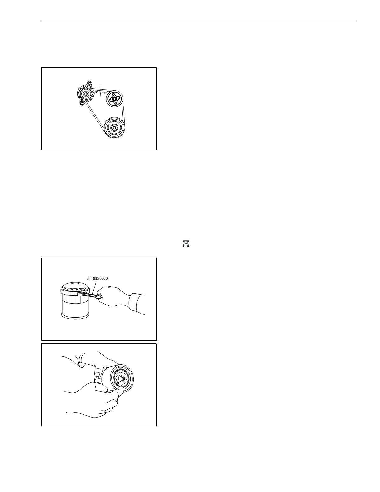
1. Visually check for cracks, wear, and oil smears.
(The belt must not contact with the bottom of the belt pulley.)
2. Check the belt deflection by pressing at the center between the
pulleys.
Fan belt deflection: 11 - 13 mm (0.43 - 0.51 in)
Force: 98N (10 kg, 22 lb)
MAM0148
REPLACE OIL AND OIL FILTER
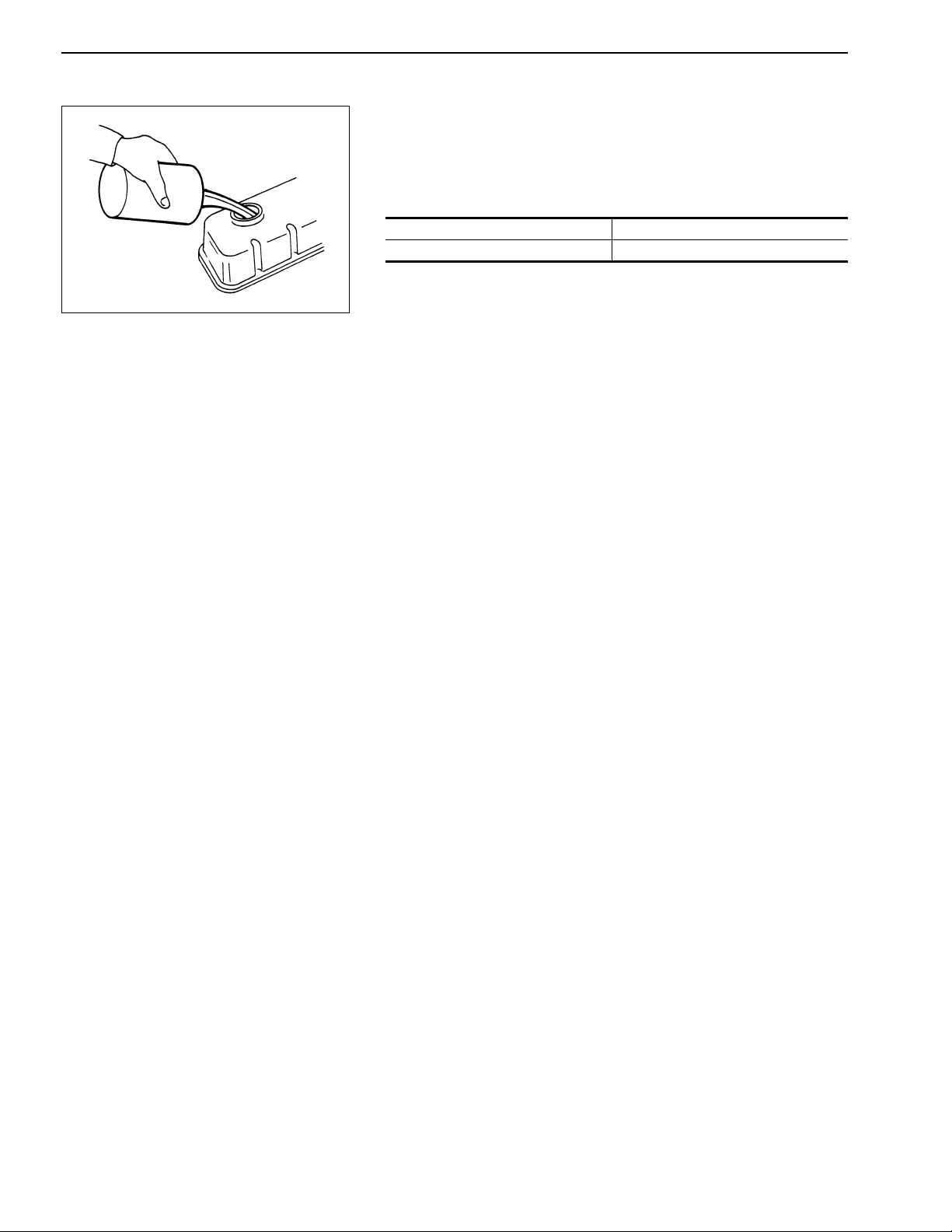
1. Start the engine and fully warm it up. Then stop the engine.
2. Remove the oil filler cap and the oil pan drain plug, and
discharge all oil.
3. After discharging oil, install the drain plug with the washer.
MAM0144
CAUTION:
• Be careful not to get burned when engine or engine oil is
heated.
• If the oil looks milky, it is contaminated with coolant.
• If the viscosity is lower than specified, the oil is mixed with
gasoline.
Tightening torque for oil pan drain plug:
29.4 - 39.2 N·m (3.0 - 4.0 kgf-m, 22 - 29 ft-lb)
4. Remove the oil filter using an oil filter wrench (SST).
5. Clean the oil filter mounting face with a clean shop cloth.
6. Apply a small amount of engine oil to the lip of the new oil filter.
7. Screw in the oil filter by hand until it contacts bracket surface,
and then screw in another 2/3 of a turn.
MAM0145
ET-9
Page 50
ENGINE INSPECTION AND ADJUSTMENT
Engine Body Related (Cont’d)
8. Fill the engine with oil of the recommended specifications and
check the oil level with the oil level gauge.
Engine oil amount
With oil filter 3.7 (4, 3-3/8)
Without oil filter 3.4 (3-3/4, 3-1/8)
Unit: liter (US qt, lmp qt)
SMA890
CAUTION:
Verify that the oil pressure warning lamp lights up before the
engine starts and turns off after the engine has started.
9. Start the engine and check the area around the drain plug and
oil filter for any leaks. If any leaks are found, the relevant part is
not installed properly.
10. Warm up the engine sufficiently. Stop the engine and wait for a
few minutes. Check the oil level and fill oil as necessary.
CAUTION:
When checking the oil level, ensure that the engine is level.
CHANGING ENGINE COOLANT
WARNING:
Do not drain coolant when engine is still hot. It may be a cause
to get burned.
CAUTION:
Before mixing antifreeze with water, carefully read the
instructions printed on the antifreeze package.
From the cylinder block plug if the engine is dismounted.
CLEAN RADIATOR OUTER FACE
Apply compressed air to the outer face of the radiator.
CHECK COOLANT HOSES AND CONNECTIONS
Check the hose connections for looseness and deterioration and
retighten or replace the hose clamps as necessary.
ET-10
Page 51
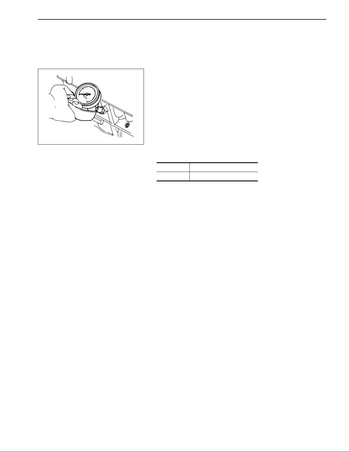
ENGINE INSPECTION AND ADJUSTMENT
Engine Body Related (Cont’d)
COMPRESSION PRESSURE INSPECTION
1. Warm up the engine sufficiently and then stop it.
Release the fuel pressure. (Electronic controlled specifications)
2. Remove the spark plug.
3. Apply a compression gauge correctly to the cylinder plug hole to
be measured.
4. Set the throttle valve to the fully-open position. Depress the
throttle pedal to the fully-open position.
5. Crank the engine and read the gauge.
(The same operations can be used for both the carburetor and
electronic control models)
• Keep the engine speed at approximately 250 rpm.
• Finish the pressure measurement in as short a time as
possible.
SMA042
Standard compression pressure
Unit: kPa (bar, kg/cm2, psi)/rpm
K21 1,226 (12.26, 12.5, 178)/250
K25 1,275 (12.75, 13.0, 185)/250
6. The compression pressure differences between cylinders must
not exceed 98 kPa (1.0 bar, 1kg/cm
2
, 14 psi)/250 rpm. If any
cylinder shows an extremely low compression pressure, put a
small amount of oil into the cylinder through the spark plug hole
and remeasure the pressure.
• If the pressure rises after filling oil, the piston ring is worn or
damaged.
• If the pressure remains unchanged even after filling oil, the
valve is stuck or inappropriately seated.
• If low compression pressure is observed in two adjacent
cylinders and the pressure is not restored even after filling
oil, the head gasket is leaking. In this case, oil and water
may enter in the combustion chamber.
• If the engine RPM is not in the specified range: Measure
the battery specific gravity.
ET-11
Page 52
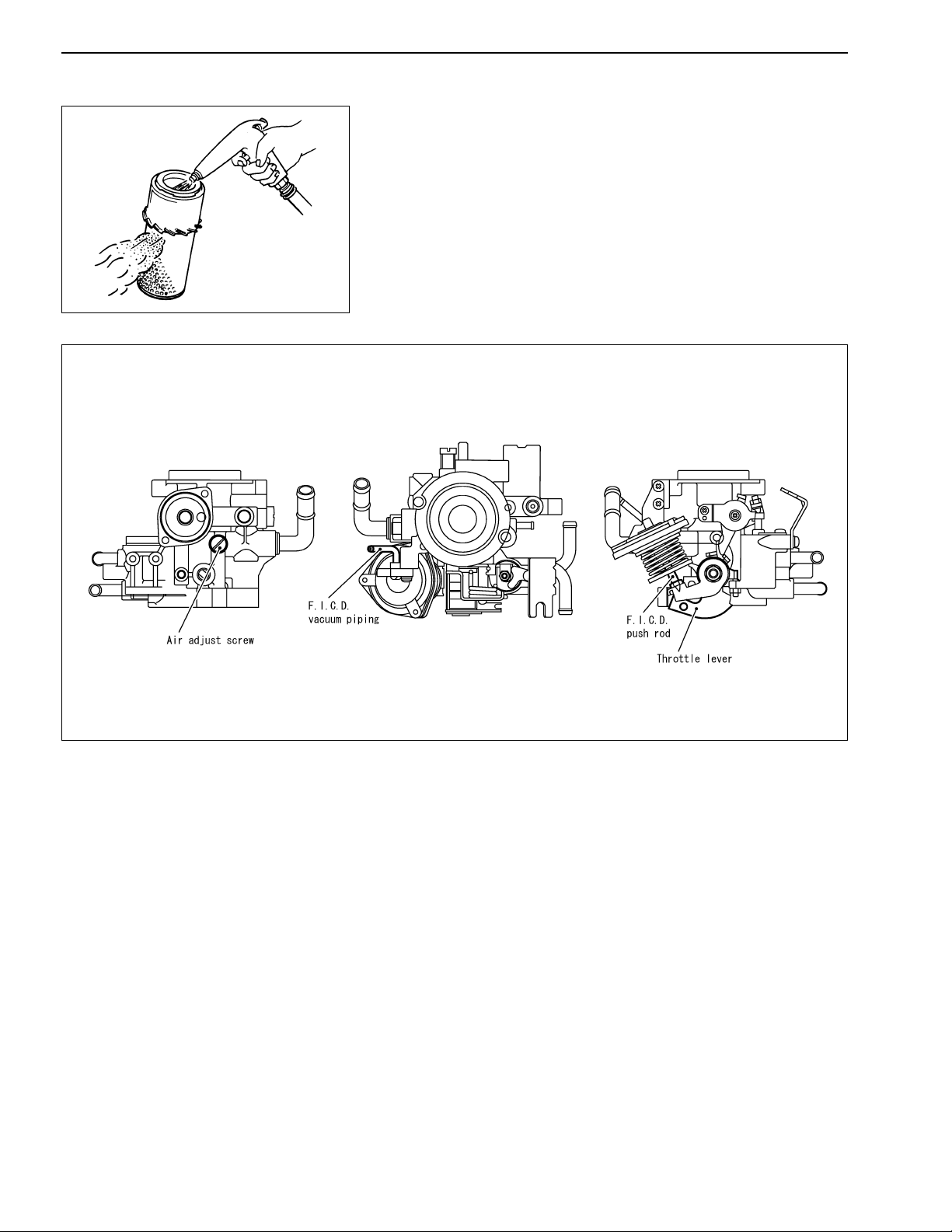
ENGINE INSPECTION AND ADJUSTMENT
Ignition and Fuel Systems
CLEANING OR REPLACEMENT OF AIR CLEANER ELEMENT
Dry filter type
It requires periodical cleaning and replacement. If the engine is used
in a heavily contaminated environment, perform maintenance more
frequently.
FET050
MIXER INSPECTION
ETM0077
Inspecting link mechanism and valves
• Remove the air horn and visually inspect the link system and
internal components.
• Check the throttle shaft for wear by attempting to move it by
hand. The throttle shaft must not move.
• Check the throttle valve and choke valve for proper operation.
(Open, close)
MIXER MAINTENANCE
• If contaminated heavily, disassemble and clean the mixer.
• If the link mechanism is excessively worn or damaged, replace
it.
• If the throttle valve shaft is excessively worn or bent, replace it.
ET-12
Page 53
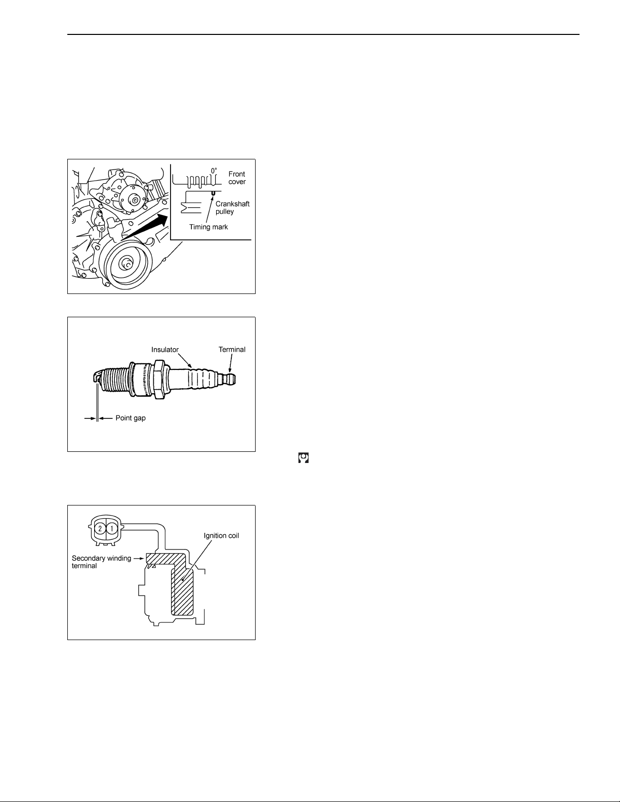
ENGINE INSPECTION AND ADJUSTMENT
Ignition and Fuel Systems (Cont’d)
FICD (fast idle control device) inspection
1. Start and warm up the engine sufficiently.
2. Check that the hot water heater is heated.
3. Check that FICD does not contact with the mixer throttle lever.
4. Adjust the idle speed by using the throttle adjusting screw and
idle adjusting screw.
Idle speed: 700 rpm
5. Adjust the ignition timing for idling.
Ignition timing: BTDC
• K21: 2°
• K25: 0°
6. Remove the vacuum piping from FICD and plug the pipe
openings to prevent air leakage.
7. In this state, the FICD pushrod is pushing the mixer throttle
lever.
Adjust the engine speed to 1,000 to 1,200 rpm with the throttle
lever adjusting screw.
ETM0054
8. After adjustment, connect the vacuum piping and verify that an
appropriate engine idle speed is obtained.
ETM0055
SPARK PLUG INSPECTION AND REPLACEMENT
1. Inspection
• Visually check electrode for dirt and damage and insulator for
burning.
• Check if the electrode gap is within the standard using a plug
gap gauge.
Standard : 0.9 mm (0.035 in)
• Adjust if outside the standard.
• Replace if necessary.
2. Installation
• Install in the reverse order of removal.
Tightening torque : 19.6 - 29.4 N·m
(2.0 - 3.0 kg-m, 14 - 22 ft-lb)
DISTRIBUTOR INSPECTION
Ignition coil inspection
• Measure resistance terminals (1) and (2) of the primary coil and
those of the secondary coil using a circuit tester.
Primary coil resistance: 0.9 - 1.2Ω
Secondary coil resistance: 20 - 29Ω
ETM0056
ET-13
Page 54
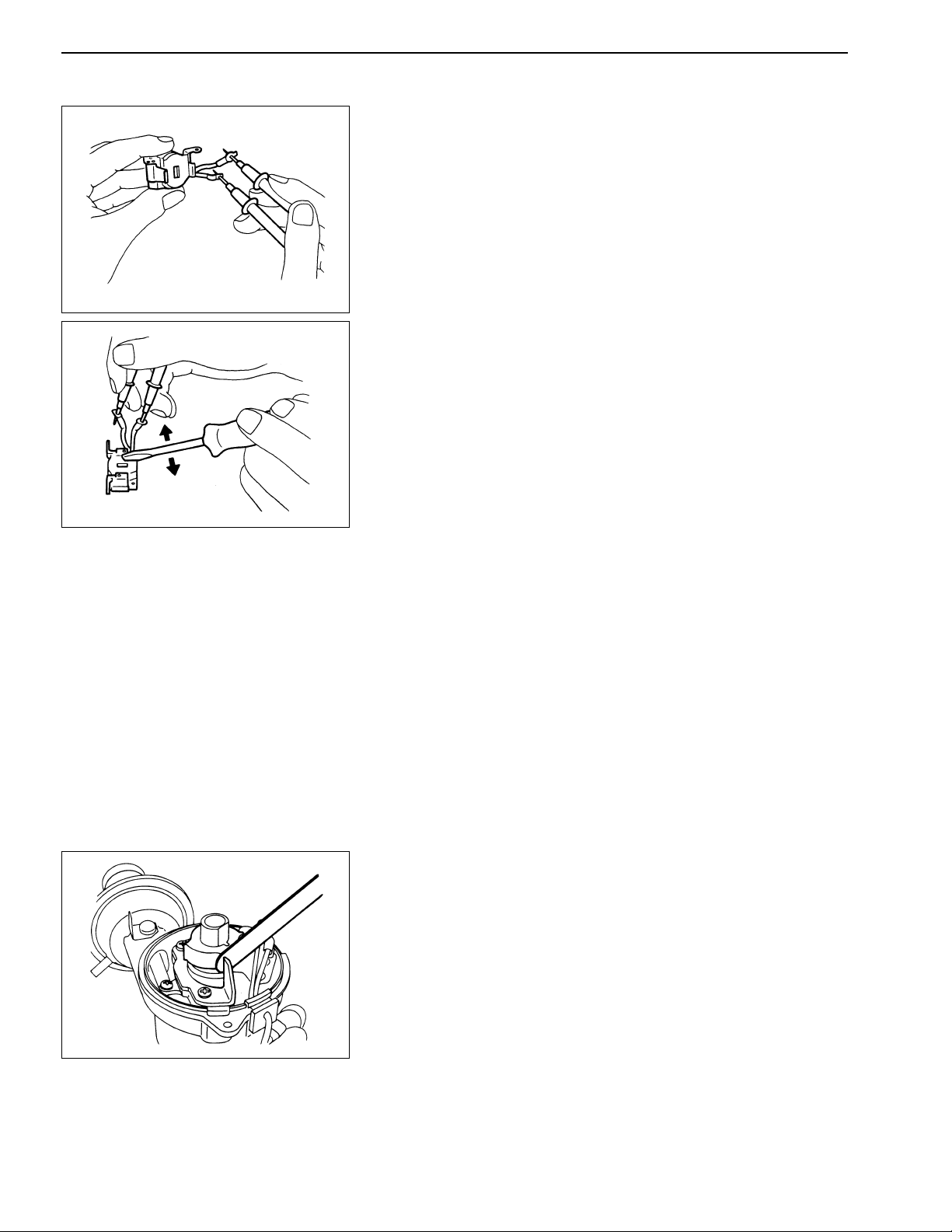
ENGINE INSPECTION AND ADJUSTMENT
Ignition and Fuel Systems (Cont’d)
Pickup coil inspection
• Measure the pickup coil resistance using a circuit tester.
Resistance: 420 - 540Ω
FET068
• Move a screwdriver to and fro near the iron core of the pickup
coil and make sure that the tester needle fluctuates.
FET069
INSPECTION OF DISTRIBUTOR CAP AND CARBON
TERMINALS
• If the hemisphere face of a terminal is worn out, replace the
cap.
ROTOR HEAD INSPECTION
• Check for cracks and damages.
SIGNAL CORE ROTOR INSPECTION
• Check for bends or damages.
VACUUM CONTROL SYSTEM INSPECTION
• Apply vacuum to the diaphragm with a vacuum pump and check
that the link is drawn.
INSPECTION AFTER REASSEMBLING DISTRIBUTOR
Measure the clearance between the signal core rotor and the pickup
coil.
Standard clearance: 0.35 - 0.45 mm (0.0138 - 0.0177 in)
SEL640B
ET-14
Page 55
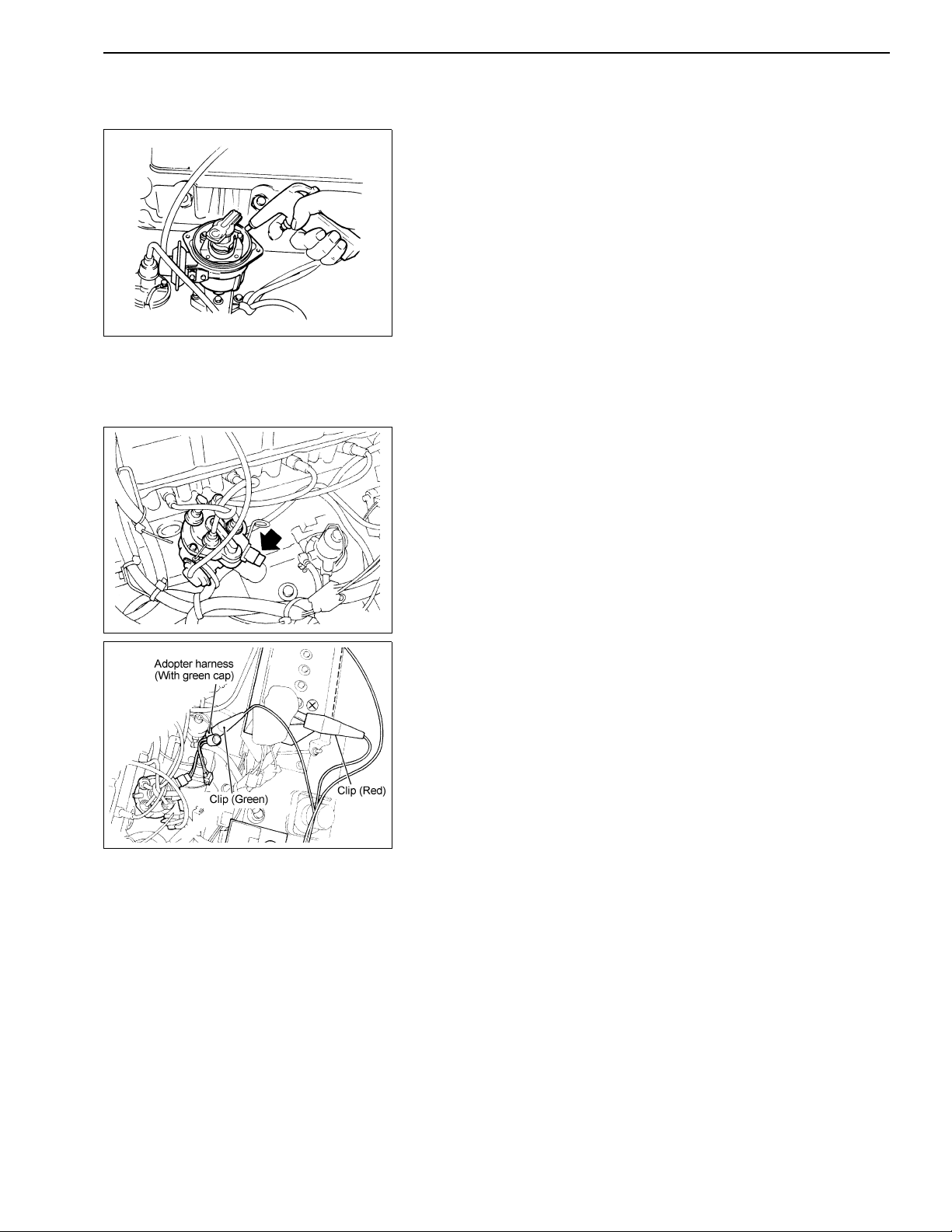
ENGINE INSPECTION AND ADJUSTMENT
Ignition and Fuel Systems (Cont’d)
CLEANING INSIDE DISTRIBUTOR
Blow any dust away from inside the distributor with dry compressed
air.
FET051
ENGINE SPEED MEASUREMENT (CARBURETOR MODEL
ONLY)
The ignition coil-integrating distributor of the K engine provides an
adapter harness for engine speed measurement.
1. Remove the distributor connector from the coupling as shown in
the figure on the left.
ETM057
ETM058
2. Connect the ignition coil adapter harness (SST: EG11140000)
between the distributor connector and the coupling.
Connect the tachometer power supply terminal (red) to the battery positive terminal and the black terminal to the battery negative terminal. Connect the measurement terminal (green) to
the measurement wire in the middle of the adapter harness.
ET-15
Page 56
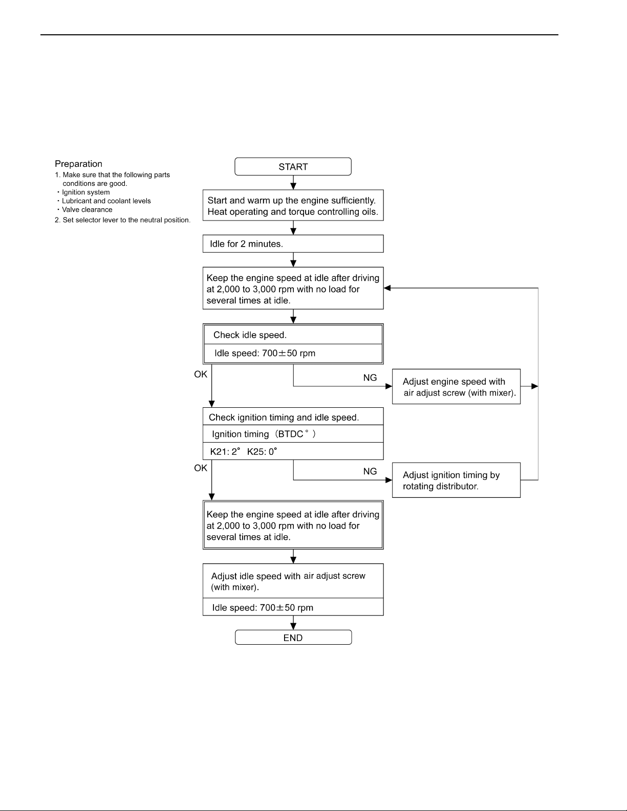
ENGINE INSPECTION AND ADJUSTMENT
Ignition and Fuel Systems (Cont’d)
INSPECTION AND ADJUSTMENT OF IGNITION TIMING, IDLE
SPEED, AIR-FUEL RATIO
a. Do not fully tighten the idle adjusting screw. Doing so damages
the screw end and leads to loss of functionality.
ET-16
ETM0078
Page 57
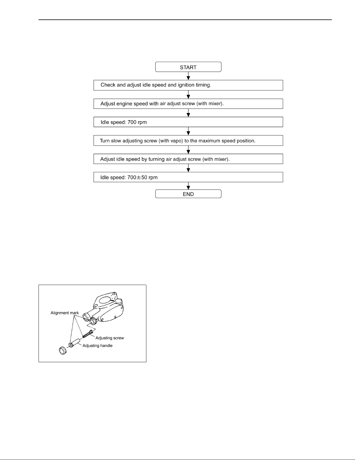
ENGINE INSPECTION AND ADJUSTMENT
Ignition and Fuel Systems (Cont’d)
INSPECTION AND ADJUSTMENT OF AIR-FUEL RATIO
ETM0059
ETM0079
GOVERNOR DEVICE
The governor requires no adjustment because it is adjusted properly
before shipment.
If it must be adjusted by any means, follow the procedure below.
ADJUSTING MAXIMUM RPM WITH NO LOAD
1. Set the forward/reverse shift lever to the neutral position.
2. Start the engine and fully open the throttle. Monitor the engine
speed.
Maximum engine speed with no load (rpm)
K21 3,000
K25 2,800
3. If the engine speed does not fall in the specified range, adjust
by turning the governor adjusting handle.
ET-17
Page 58
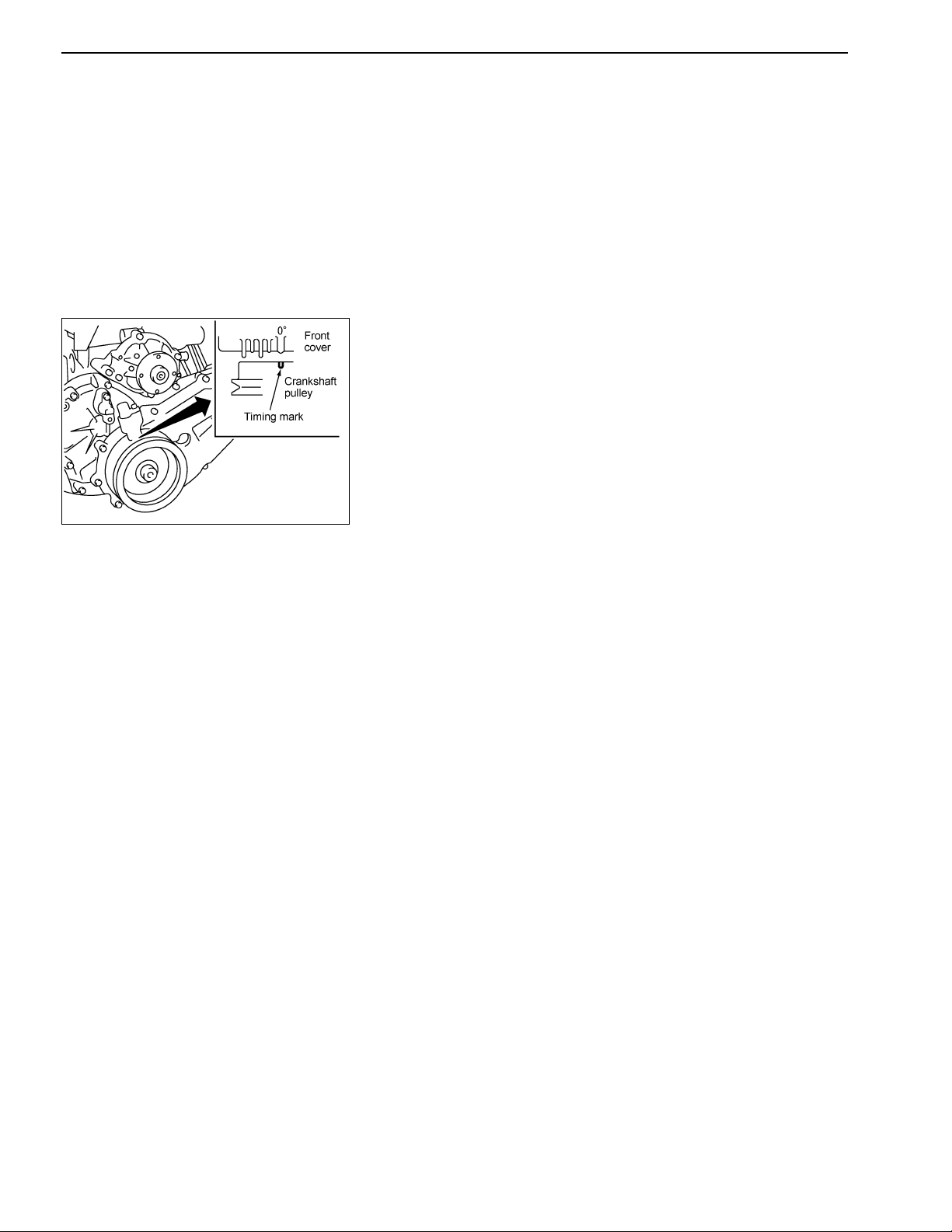
ENGINE INSPECTION AND ADJUSTMENT
Ignition and Fuel Systems (Cont’d)
ADJUSTING MAXIMUM RPM WITH LOAD
1. Set the forward/reverse shift lever to the neutral position.
2. Start the engine and fully tilt the mast rearward with the tilt lever.
3. Fully open the throttle and monitor the engine speed.
Maximum engine speed with load (rpm)
K21 2,750
K25 2,600
4. If the engine speed does not fall in the specified range, adjust
by turning the governor adjusting handle. In addition, adjust the
maximum engine speed with no load.
FICD (FAST IDLE CONTROL DEVICE) INSPECTION
1. Start and warm up the engine sufficiently.
2. Check that FICD does not contact the carburetor throttle lever.
3. Adjust the idle speed by using the throttle adjusting screw and
idle adjusting screw.
Idle speed: 700±50 rpm
4. Adjust the ignition timing for idling.
Ignition timing: BTDC
K21: 2°
K25: 0°
ETM0054
5. Remove the vacuum piping from FICD and plug the pipe
openings to prevent air leakage.
6. In this state, the FICD pushrod is pushing the carburetor throttle
lever.
Adjust the engine speed to 1,000 to 1,200 rpm with the throttle
lever adjusting screw.
7. After adjustment, connect the vacuum piping and verify that an
appropriate engine idle speed is obtained.
ET-18
Page 59
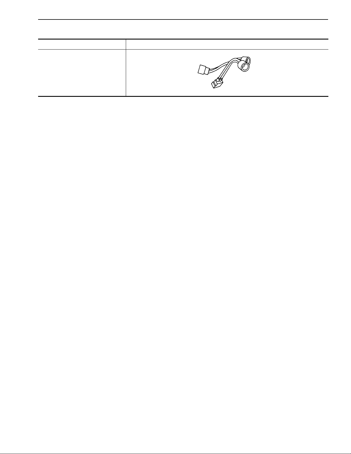
SPECIAL SERVICE TOOLS FOR CARBURETOR MODEL
SPECIAL SERVICE TOOLS FOR CARBURETOR MODEL
Tool number Tool name
EG11140000 Ignition coil
Adapter harness
For checking engine speed
ETM0060
ET-19
Page 60
ENGINE MECHANICAL
CONTENTS
PRECAUTIONS ..................................................EM-2
Precautions for Draining Engine Coolant .......EM-2
Precautions for Disconnecting Fuel Piping .....EM-2
Precautions for Removing and
Disassembling ................................................EM-2
Precautions for Inspection, Correction, and
Replacement ..................................................EM-2
Precautions for Assembly and Installation .....EM-2
Parts Requiring Angle Tightening ...................EM-3
Caution for Use of Power Tools .....................EM-3
Precautions for Liquid Gasket Application ......EM-3
MAIN SPECIFICATIONS ....................................EM-4
ADJUSTMENT VALUE .......................................EM-5
TIGHTENING TORQUE ......................................EM-8
Standard Bolt Tightening Torque ...................EM-8
Engine Part Tightening Torque ......................EM-9
SECTION
TROUBLE DIAGNOSIS ....................................EM-11
SPECIAL SERVICE TOOLS .............................EM-13
REMOVAL AND INSTALLATION
OF ENGINE .......................................................EM-14
Removal .......................................................EM-14
Installation ....................................................EM-15
Inspection ..................................................... EM-15
ENGINE SERVICE ............................................EM-16
Engine Disassembly ..................................... EM-16
Inspection and Correction ............................EM-22
Engine Assembly ..........................................EM-35
EM
Page 61

PRECAUTIONS
PRECAUTIONS
Precautions for Draining Engine Coolant
• Drain coolant only after the engine has cooled down.
Precautions for Disconnecting Fuel Piping
• Operation should be done in a place free from fire.
• After disconnecting, plug the pipe to prevent fuel from draining.
Precautions for Removing and
Disassembling
• Use correct SSTs in the specified position. Always pay attention
to safety.
• Be careful not to lose surface accuracy of mating or sliding
surfaces.
• To prevent foreign material from entering the engine, close
openings with appropriate tape as necessary.
• Arrange disassembled parts in their normal positions in order to
simplify locating the cause of damage or excessive wear and to
ensure correct reassembly.
• As a rule, nuts and bolts must be tightened in a diagonal
manner starting from an outer one. If a particular tightening
sequence is provided separately, follow the sequence.
Precautions for Inspection, Correction, and
Replacement
• Following the inspection procedure, inspect the parts
adequately and repair or replace as necessary. Perform the
same inspections even for new parts and replace them if
necessary.
Precautions for Assembly and Installation
• Always use a torque wrench when tightening nuts and bolts.
• Unless otherwise specified, tighten bolts and nuts from inside to
outside in a crisscross pattern. Tighten them gradually and
evenly in 2 to 3 steps.
• Always replace gasket, packing, oil seals, and O-rings with new
ones.
• For each part, perform adequate cleaning/washing and drying
with a dryer. In particular, ensure that the oil and coolant
passages are free from plugging and clogging.
• Remove any dirt and lint on sliding and mating surfaces. Before
assembly, apply ample amount of engine oil to sliding surfaces.
• If coolant was drained, bleed air from the system.
• After assembly, start engine and increase the engine speed,
then check coolant, fuel, oil, grease, and exhaust gas for
leakage.
EM-2
Page 62
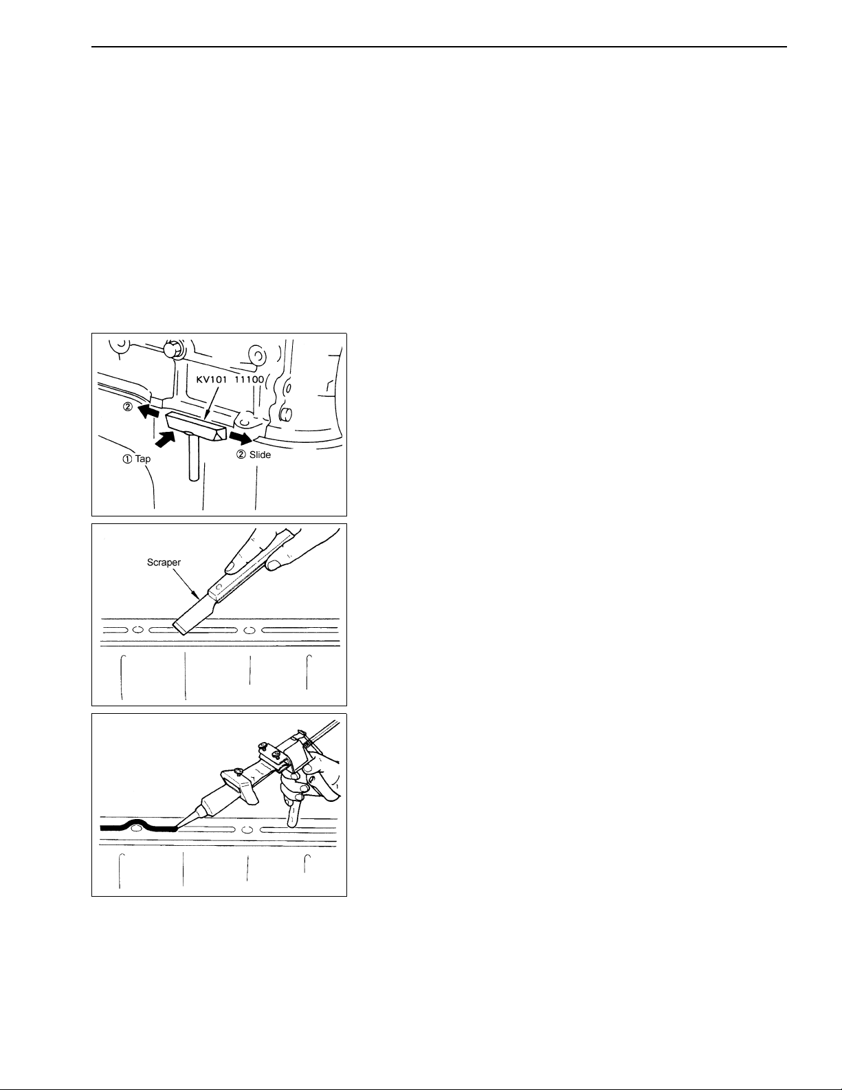
GIM0061
PRECAUTIONS
Parts Requiring Angle Tightening
• When tightening the following parts, use an angle wrench
(SST).
• Cylinder head bolt
Before assembly, verify that no grease/oil and dust are present
on the cylinder head, cylinder block mounting face, and head
gasket. Then apply antirust oil or engine oil to the threads and
head bottoms of the head bolts.
Caution for Use of Power Tools
• The use of power tools such as an air runner are only allowed
for disassembly. Do not use them for assembly.
Precautions for Liquid Gasket Application
REMOVING PARTS ATTACHED WITH LIQUID GASKET
• Remove mounting nuts and bolts. Remove liquid gasket using a
seal cutter (SST).
CAUTION:
• Be careful not to damage the mating surfaces.
• In positions where a seal cutter is difficult to use, lightly tap
with a plastic hammer, and remove.
• Be careful not to scratch the mating surfaces when using a
screwdriver.
GIM0062
GIM0063
LIQUID GASKET APPLICATION INSTRUCTION
1. Remove any old liquid gasket remaining on the gasket
application surface and its mating surface using a scraper.
• Remove any old liquid gasket remaining in the gasket
application groove and on the threads of bolts and bolt
holes.
2. Wipe the gasket application surface and its mating surface
using Isozole or any equivalent thinner to remove any moisture,
oil, and foreign material.
3. Set genuine liquid gasket to tube presser (commercial service
tool).
4. Apply a continuous bead of liquid gasket to the specified
position at the specified diameter.
• Apply liquid gasket in the application groove.
• Apply liquid gasket inside bolt holes as a rule. Make sure to
carefully read the relevant instructions.
• Attaching should be done within 5 minutes after gasket
application.
• Immediately wipe off any protruding liquid gasket.
• Do not retighten nuts and bolts after installation.
• After finishing work, wait at least 30 minutes before refilling
engine oil and coolant.
CAUTION:
Follow any directions specified in the text on the following
pages.
EM-3
Page 63
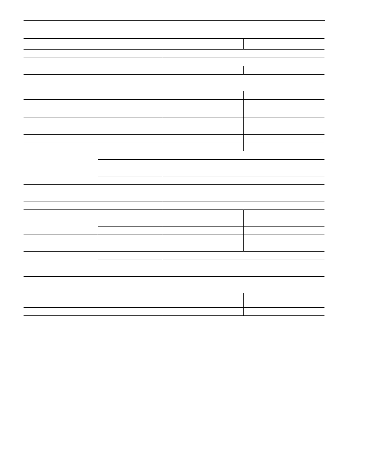
MAIN SPECIFICATIONS
MAIN SPECIFICATIONS
Engine type K21 K25
Engine control system Mixer Specifications
Fuel specification LPG
Total displacement (cc) 2,065 2,488
Shape of combustion chamber Bathtub
Valve mechanism OHV
Bore x stroke mm (in) 89 x 83 (3.50 x 3.27) 89 x 100 (3.50 x 3.94)
Compression ratio 8.7 8.7
Compression pressure [kPa (bar, kg/cm
Engine speed control system Pneumatic governor Pneumatic governor
Fuel in use (Note 1) At 20P At 20P
Maximum output [kW/rpm] 30.5 /2,400 35 /2,400
Maximum torque [N·m /rpm] 140 /1,600 170 /1,600
Valve opening/closing timing
(degree)
Valve clearance mm (in) Intake (when engine is hot) 0.38 (0.0150)
Firing order 1-3-4-2
Ignition timing (idling) (BTDC deg.) 2 0
On board idle speed (rpm) ATM 700 700
On board high-idle speed (rpm) ATM 3,000 2,800
Allowable maximum engine
speed (rpm)
PTO system Silent chain-driven/side PTO
Engine oil (originally fitted) Specification 10W-30 (Class SJ)
Engine dimensions (length x width x height) (Note 2) mm 707 x 560 x 720 707 x 560 x 720
2
, psi)/rpm]
Intake open (BTDC) 14
Intake close (ABDC) 30
Exhaust open (BBDC) 32
Exhaust close (ATDC) 12
Exhaust (when engine is hot) 0.38 (0.0150)
MTM 700 700
MTM 3,000 2,800
Instantaneous, no load 3,600
Continuous load 3,000
Amount 2 (Imp qt) 3.7 (3-1/4) (including oil filter)
1,226 (12.2, 12.5, 178)/250 1,226 (12.2, 12.5, 178)/250
Engine weight (w/o coolant, w/ oil) (Note 2) kg (lb) 143 (315) 145 (320)
Note 1: Fuel
LPG: Use a fuel of 20P or more in cold seasons. In ambient
temperature of -5°C or less, use a 100P fuel.
Note 2: The engine dimensions and weight differ with the customer
specifications. The above data should be deemed as
reference.
EM-4
Page 64

ADJUSTMENT VALUE
ADJUSTMENT VALUE
VALVE MECHANISM
• Valve clearance (Hot) : mm (in)
Standard Intake 0.38 (0.015)
Exhaust 0.38 (0.015)
VALVE
• Head outer diameter : mm (in)
Standard Intake 38.0 - 38.3 (1.496 - 1.508)
Exhaust 32.0 - 32.3 (1.260 - 1.272)
• Valve total length
Intake 98.85 - 99.45 (3.892 - 3.915)
Exhaust 98.95 - 99.55 (3.896 - 3.919)
• Valve stem outer diameter : mm (in)
Standard Intake 6.97 - 6.985 (0.2744 - 0.2750)
Exhaust 6.945 - 6.960 (0.2734 - 0.2740)
• Valve spring free length
Intake and exhaust : mm (in) 45.9 (1.807)
Valve-opening compressed length
Inta ke a nd exha u st mm / N (mm / kg , i n /l b )
25.0/347.0 - 391.2 (25.0/35.4 - 39.9, 0.984/78.1 - 88.0)
Valve spring installation length (when closed)
Intake and exhaust mm/N (mm/kg, in/lb)
33.8/177.9 - 200.7(33.8/18.1 - 20.5, 1.331/40.0 - 45.1)
Valve spring slant
Intake and exhaust : mm (in) 1.5 (0.059)
• Clearance between valve stem and valve guide : mm (in)
Standard Intake 0.015 - 0.048 (0.0006 - 0.0019)
Exhaust 0.040 - 0.073 (0.0016 - 0.0029)
Repair limit Intake 0.10 (0.0039)
Exhaust 0.10 (0.0039)
Valve seat width
Intake 1.1 - 1.4 (0.043 - 0.055)
Exhaust 1.8 - 2.2 (0.071 - 0.087)
Valve seat angle
Intake and
exhaust. 44°23
Valve face angle
Intake 45°15
Exhaust 44°30' ~ 45°
Camshaft
• Bend : mm (in)
Repair limit 0.05 (0.0020)
• End play : mm (in)
Standard 0.15 - 0.23 (0.0059 - 0.0091)
Repair limit 0.40 (0.0157)
• Journal dimensions : mm (in)
Standard Front 45.434 - 45.447 (1.7887 - 1.7892)
Center 43.897 - 43.910 (1.7282 - 1.7287)
Rear 41.218 - 41.231 (1.6228 - 1.6233)
• Oil clearance at journal : mm (in)
Standard Front 0.025 - 0.051 (0.0010 - 0.0020)
Center 0.038 - 0.064 (0.0015 - 0.0025)
Rear 0.025 - 0.051 (0.0010 - 0.0051)
Repair limit Front 0.10 (0.0039)
Center 0.15 (0.0059)
Rear 0.10 (0.0039)
' ~ 45°07'
' ~ 45°45'
EM-5
Page 65

ADJUSTMENT VALUE
• Camshaft height : mm (in)
Standard 36.750 - 36.800 (1.4468 - 1.4488)
(For both intake and exhaust)
Size reduction limit 36.5 (1.437)
CRANKSHAFT
• Bend : mm (in)
Repair limit 0.05 (0.0020)
• End play : mm (in)
Standard 0.05 - 0.18 (0.0020 - 0.0071)
Repair limit 0.20 (0.0079)
• Journal dimensions : mm (in)
Standard 62.942 - 62.955 (2.4780 - 2.4785)
• Pin standard dimension : mm (in)
Standard 44.961 - 44.974 (1.7701 - 1.7706)
• Oil clearance at journal : mm (in)
Standard 0.020 - 0.073 (0.0008 - 0.0029)
Repair limit 0.10 (0.0039)
FLATNESS OF FLYWHEEL AND DRIVE PLATE
• Flatness of flywheel : mm (in)
Repair limit 0.10 (0.0039)
• Runout of drive plate : mm (in)
Repair limit 0.20 (0.0079)
• Flatness of ring gear : mm (in)
Repair limit 0.50 (0.0197)
• Flatness : mm (in)
Repair limit 0.30 (0.0118)
CONNECTING ROD
• Center distance between both end holes : mm (in)
Standard 143.970 - 144.030
(5.6681 - 5.6705) (K25)
152.47 - 152.53
(6.0027 - 6.0051) (K21)
• Large end hole diameter : mm (in)
Standard 48.0 - 48.013 (0.7807 - 1.8903)
• Small end hole diameter : mm (in)
Standard 19.965 - 19.978 (0.7860 - 0.7865)
• Bend [per 100 mm (3.94 in)] : mm (in)
Repair limit 0.05 (0.0020)
• Twist [per 100 mm (3.94 in)] : mm (in)
Repair limit 0.05 (0.0020)
• Large end thrust clearance : mm (in)
Standard 0.2 - 0.3 (0.008 - 0.012)
Repair limit 0.40 (0.0157)
• Large end oil clearance : mm (in)
Standard 0.032 - 0.060 (0.0013 - 0.0024)
Repair limit 0.10 (0.0039)
• Weight difference (piston combination): g (oz)
Standard 5 (0.18) or less
EM-6
Page 66

ADJUSTMENT VALUE
PISTON
• Piston : mm (in)
Type Thermal flow type
Material Aluminum alloy
Outer diameter
Standard 88.965 - 89.015 (3.5026 - 3.5045)
• Clearance to cylinder : mm (in)
Standard 0.025 - 0.045 (0.0010 - 0.0018)
• Piston pin outer diameter : mm (in)
Standard 19.993 - 19.998 (0.7871 - 0.7873)
• Piston pin fitting quality
Standard To a degree allowing movement by hand
• Piston ring closed gap : mm (in)
Standard Top 0.28 - 0.43 (0.0110 - 0. 0169)
Second 0.45 - 0.60 (0.0177 - 0.0236)
Oil 0.20 - 0.60 (0.0079 - 0.0236)
Various limit values 1.00 (0.0039)
• Clearance between piston ring and ring groove : mm (in)
Standard Top 0.04 - 0.08 (0.0016 - 0.0032)
Second 0.03 - 0.07 (0.0012 - 0.0028)
Oil 0.65 - 0.135 (0.0256 - 0.0053)
Repair limit Top 0.10 (0.0039)
Second 0.10 (0.0039)
Oil —
Pin outer diameter : mm (in)
19.993 - 19.998 (0.7871 - 0.7873)
CYLINDER HEAD
Valve guide : mm (in)
Standard 7.000 - 7.018 (0.2756 - 0.2763)
(for both intake and exhaust)
Valve stem-to-valve guide clearance : mm (in)
Repair limit 0.10 (0.0039)
(for both intake and exhaust)
CYLINDER BLOCK
Cylinder bore inner diameter : mm (in)
Standard 89.00 - 89.05 (3.5089 - 3.5059)
Wear limit 0.2 (0.0079)
Cylinder bore taper and out-of-round : mm (in)
0.2 (0.0008)
Top face distortion limit : mm (in) 0.05 (0.0020)
Distortion limit : mm (in)
Intake manifold 0.1 (0.004)
Exhaust manifold 0.3 (0.012)
Cylinder head 0.1 (0.004)
Cylinder block 0.1 (0.004)
EM-7
Page 67
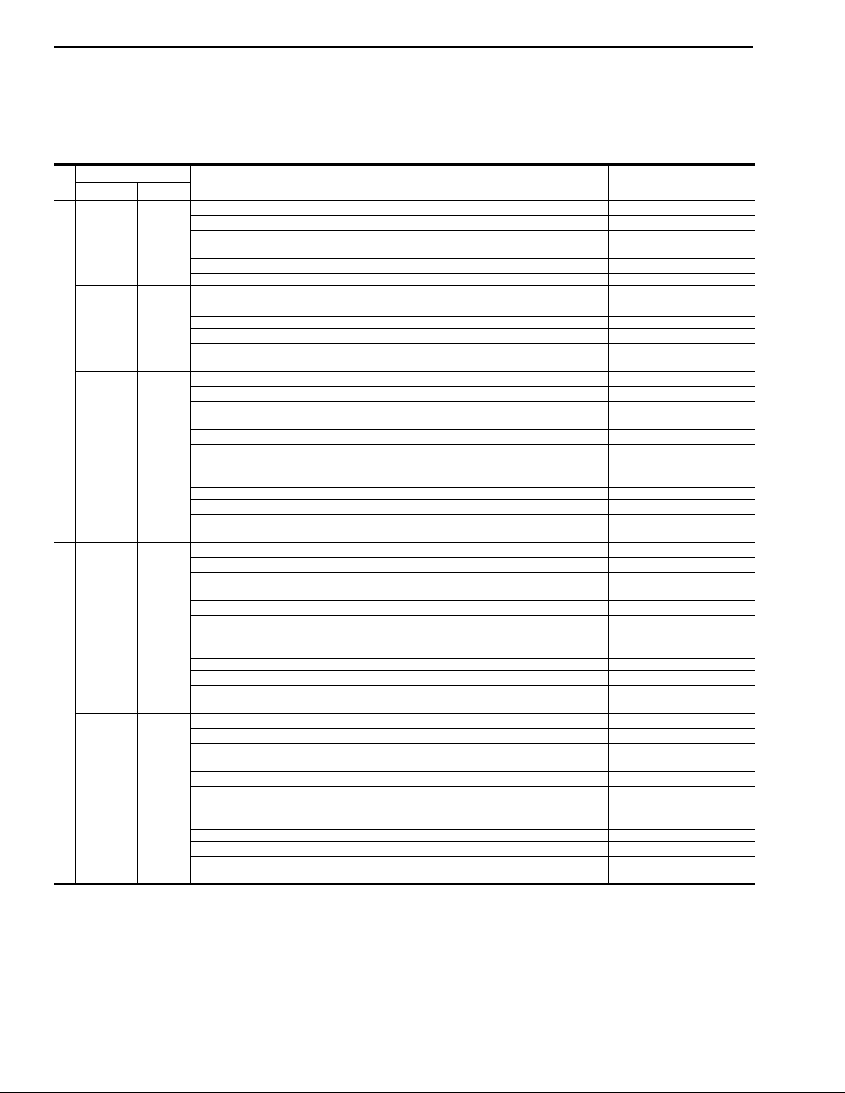
TIGHTENING TORQUE
TIGHTENING TORQUE
Thread size
Diameter Pitch
M6 1
M8 1.25
1.25
Hexagon head bolt and nut
M10
M6 1
M8 1.25
Flanged bolt
1.25
M10
1.5
1.5
Standard Bolt Tightening Torque
Upper: Lubricated (Antirust oil is applied to abrasive faces of
threads and seating faces)
Lower: No lubrication (Threads and seating faces are completely
degreased)
Unit 4T (Bolt) 7T (Bolt) 9T (Bolt)
N•m
kg-m
ft-lb, in-lb* 34 - 39* 56 - 66* 82 - 95*
N•m
kg-m
ft-lb, in-lb* 44 - 57* 75 - 95* 9 - 12
N•m
kg-m
ft-lb, in-lb* 82 - 95 12 - 13 17 - 19
N•m
kg-m
ft-lb, in-lb* 9 - 12 15 - 20 22 - 27
N•m
kg-m
ft-lb, in-lb* 14 - 17 24 - 28 35 - 40
N•m
kg-m
ft-lb, in-lb* 19 - 25 32 - 41 46 - 58
N•m
kg-m
ft-lb, in-lb* 14 - 16 22 - 27 33 - 38
N•m
kg-m
ft-lb, in-lb* 18 - 23 30 - 38 43 - 55
N•m
kg-m
ft-lb, in-lb* 43 - 50* 72 - 84* 9 - 10
N•m
kg-m
ft-lb, in-lb* 53 - 68* 87 - 113 11 - 14
N•m
kg-m
ft-lb, in-lb* 9 - 10 14 - 17 21 - 25
N•m
kg-m
ft-lb, in-lb* 11 - 14 18 - 23 26 - 33
N•m
kg-m
ft-lb, in-lb* 18 - 22 30 - 35 44 - 51
N•m
kg-m
ft-lb, in-lb* 22 - 29 38 - 48 54 - 69
N•m
kg-m
ft-lb, in-lb* 17 - 20 29 - 34 42 - 48
N•m
kg-m
ft-lb, in-lb* 22 - 27 36 - 46 51 - 66
3.8
- 4.4 6.4 - 7.5 9.2 - 10.8
0.39
- 0.45 0.65 - 0.76 0.94 - 1.1
- 6.5 8.4 - 10.8 11.8 - 15.7
5.0
0.51
- 0.66 0.86 - 1.1 1.2 - 1.6
9.3
- 10.8 15.7 - 17.7 22.6 - 25.5
- 1.1 1.6 - 1.8 2.3 - 2.6
0.95
12.7
- 15.7 20.6 - 26.5 29.4 - 37.3
- 1.6 2.1 - 2.7 3.0 - 3.8
1.3
19.6
- 22.6 32.4 - 38.2 47.1 - 53.9
- 2.3 3.3 - 3.9 4.8 - 5.5
2.0
- 33.3 43.1 - 54.9 61.8 - 78.5
25.5
- 3.4 4.4 - 5.6 6.3 - 8.0
2.6
18.6
- 21.6 30.4 - 36.3 44.1 - 52
- 2.2 3.1 - 3.7 4.5 - 5.3
1.9
- 31.4 41.2 - 52 58.8 - 74.5
24.5
- 3.2 4.2 - 5.3 6.0 - 7.6
2.5
- 5.7 8.14 - 9.51 11.8 - 13.7
4.9
- 0.58 0.83 - 0.97 1.2 - 1.4
0.5
- 7.7 9.8 - 12.7 14.7 - 18.6
6.0
- 0.78 1.0 - 1.3 1.5 - 1.9
0.61
11.8
- 13.7 19.6 - 23.5 28.4 - 33.3
- 1.4 2.0 - 2.4 2.9 - 3.4
1.2
14.7
- 18.6 24.5 - 31.4 35.3 - 45.1
- 1.9 2.5 - 3.2 3.6 - 4.6
1.5
- 29.4 41.2 - 48.1 59.8 - 69.6
24.5
- 3.0 4.2 - 4.9 6.1 - 7.1
2.5
- 39.2 51.0 - 64.7 73.6 - 93.2
30.4
- 4.0 5.2 - 6.6 7.5 - 9.5
3.1
23.5
- 27.5 39.2 - 46.1 56.9 - 65.7
- 2.8 4.0 - 4.7 5.8 - 6.7
2.4
- 37.3 49.0 - 61.8 69.6 - 89.2
29.4
- 3.8 5.0 - 6.3 7.1 - 9.1
3.0
CAUTION:
• Except special nuts and bolts.
• The bolts applicable to this table have one of the following
marks embossed on their heads.
4T......4
7T......7
9T......9
EM-8
Page 68
TIGHTENING TORQUE
TAPER SCREW TIGHTENING TORQUE
Allowable materials
for tightening
Normal size
Unit
R1/8 N•m 7.8 11.8 15.7 21.6
kg-m 0.796 1.2 1.6 2.2
ft-lb, in-lb* 69* 9 12 16
R1/4 N•m 19.6 29.4 34.3 44.1
kg-m 2.0 3.0 3.5 4.5
ft-lb, in-lb* 14 22 25 33
R3/8 N•m 39.2 54.9 53.9 73.5
kg-m 4.0 5.6 5.5 7.5
ft-lb, in-lb* 29 41 40 54
Aluminum Cast iron
Standard Max. value Standard Max. value
Engine Part Tightening Torque
TIGHTENING TORQUE AT VARIOUS POINTS OF ENGINE
Tightening point Unit Standard Max. value
Cylinder head (lubricated) Separately given
Main bearing cap (lubricated) Separately given
Crankshaft pulley bolt (lubricated)
Flywheel bolt (lubricated)
Connecting rod nut (lubricated)
Rear plate bolt
Camshaft sprocket bolt
Oil filter stud
Oil filter element
Spark plug
Engine slinger bolt
Rocker cover nut
Water temperature gauge
Oil pressure switch
Exhaust manifold nut
Straight screw plug (For head top face)
Oil pan drain plug
Fuel tube flare nut
Thermo-housing relief plug
N•m 220.5 240.1
kg-m 22.5 24.5
ft-lb, in-lb* 163 177
N•m 132 142
kg-m 13.47 14.49
ft-lb, in-lb* 97 105
N•m 31.4 37.3
kg-m 3.2 3.81
ft-lb, in-lb* 23 28
N•m 44.1 58.8
kg-m 4.5 6.0
ft-lb, in-lb* 33 43
N•m 39.2 49
kg-m 4.0 5.0
ft-lb, in-lb* 29 36
N•m 29.4 39.2
kg-m 3.0 4.0
ft-lb, in-lb* 22 29
N•m 14.7 20.6
kg-m 1.5 2.1
ft-lb, in-lb* 11 15
N•m 19.6 29.4
kg-m 2.0 3.0
ft-lb, in-lb* 14 22
N•m 22.6 25.5
kg-m 2.31 2.6
ft-lb, in-lb* 17 22
N•m 13.7 15.7
kg-m 1.4 1.6
ft-lb, in-lb* 10 12
N•m 15.7 19.6
kg-m 1.6 2.0
ft-lb, in-lb* 12 14
N•m 15.7 21.6
kg-m 1.6 2.2
ft-lb, in-lb* 12 16
N•m 41.2 48.1
kg-m 4.2 4.91
ft-lb, in-lb* 30 36
N•m 44.1 58.9
kg-m 4.5 5.5
ft-lb, in-lb* 33 40
N•m 29.4 39.2
kg-m 3.0 4.0
ft-lb, in-lb* 22 29
N•m 16.0 23.0
kg-m 1.63 2.35
ft-lb, in-lb* 12 17
N•m 6.37 7.45
kg-m 0.65 0.76
ft-lb, in-lb* 56* 66*
EM-9
Page 69
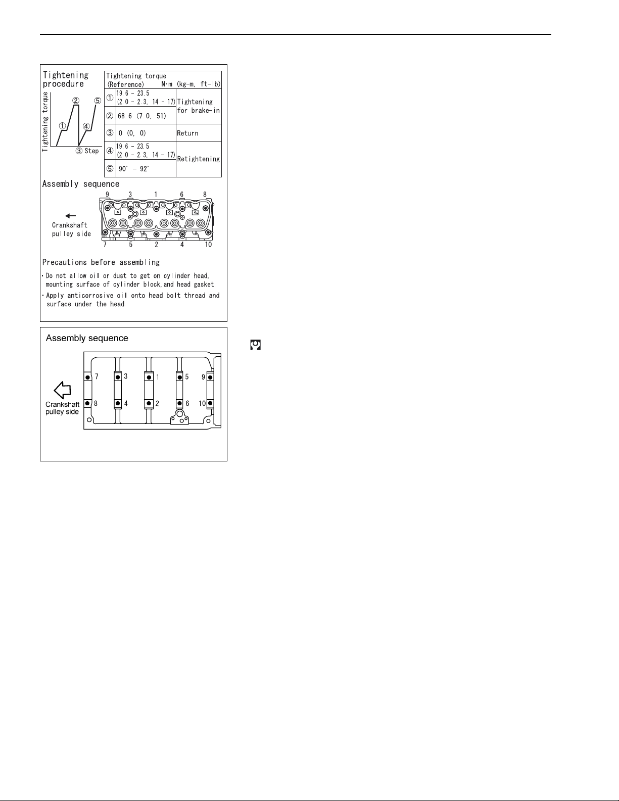
TIGHTENING TORQUE
CYLINDER HEAD
Tightening torque for general service is 68.6 N·m (7.0 kg-m, 51 ft-lb)
in the place of the tightening torque (5) as shown in the figure.
MAM0147
MAIN BEARING CAP
: 83.4 - 93.2 N•m (8.51 - 9.51kg-m, 61.6 - 68.8 ft-lb)
• Apply antirust oil or engine oil to the bolt threads and head
bottom.
• Do not use any power tools such as an air runner for assembly.
GIM0064
EM-10
Page 70
TROUBLE DIAGNOSIS
TROUBLE DIAGNOSIS
Condition Possible causes Action
1. Engine noise
Slapping noise of bearing and crankshaft Bearing looseness Replace.
Bearing seizure Replace.
Crankshaft bend Repair or replace.
Uneven wear of journal Correct.
Excessive end play Replace center bearing.
Slapping noise of piston, connecting rod Bearing looseness Replace.
Bearing seizure Replace.
Piston looseness Replace piston pin(s) or bushing(s).
Piston looseness relative to cylinder Reselect.
Piston ring damage Replace.
Poor rod alignment Realign.
Slapping noise of camshaft Bearing looseness Replace.
Excessive axial looseness Replace bearing thrust plate(s).
Rough gear tooth face(s) Correct.
Gear damage Replace.
Timing chain noise Inappropriate tension Adjust.
Damaged or sagged chain Replace.
Worn sprocket Replace.
Damaged or loose tensioner Replace.
Excessive camshaft-to-bearing clearance Replace.
Slapping noise of valve gear Inappropriate valve clearance Adjust.
Loose adjustment screw(s) Replace.
Worn rocker face(s) Replace.
Worn valve guide(s) Replace guide(s).
Loose valve spring(s) Replace.
Valve seizure Repair or replace.
Slapping noise of water pump Inappropriate end play Replace.
Damaged impeller Replace.
2. Other mechanical damage
Stuck valve Inappropriate clearance Adjust.
Valve stem - insufficient guide-to-guide clearance Clean stem(s), ream guide(s).
Loose or damaged spring Replace.
Seized or damaged valve stem(s) Replace or clean.
Poor fuel quality Use good fuel.
Burnt valve seat(s) Inappropriate valve clearance Adjust.
Deteriorated valve spring(s) Replace.
Edged valve end(s) Replace Bulb.
Too narrow valve seat width Correct valve seat(s).
Engine over temperature (Overheat) Repair or replace.
Overrun Operate in optimum speed range.
Stuck valve guide(s) Correct.
EM-11
Page 71
TROUBLE DIAGNOSIS
Condition Possible causes Action
Excessive wear of cylinder piston(s) Insufficient engine oil Refill or replace oil.
Contaminated engine oil Clean crankcase, replace oil filter.
Poor quality oil Use specified oil.
Engine over temperature (Overheat) Repair or replace.
Wrong combination of piston and connecting rod Repair or replace.
Inappropriate clearance of piston ring Reselect and adjust.
Piston ring damage Replace.
Damaged air cleaner Wash.
Too rich air-fuel mixture Adjust.
Overrun Operate in optimum speed range.
Stuck choke valve Clean and adjust.
Excessive use of choke valve Start engine properly.
Poor functioning of connecting rod(s) Insufficient engine oil Fill oil.
Low oil pressure Repair.
Use of poor quality oil Use specified oil.
Rough crankshaft surface(s) Grind surface(s), replace bearing(s).
Plugged oil passage Clean.
Wear or damage of bearing Replace.
Inappropriate bearing Correct.
Bearing looseness Replace.
Poor connecting rod alignment Repair or replace.
Poor functioning of crankshaft bearing(s) Insufficient engine oil Fill or replace oil.
Low oil pressure Correct.
Use of poor quality oil Use specified oil.
Uneven wear of crankshaft journal(s) Repair
Plugged oil passage of crankshaft Wash.
Wear or damage of bearing Replace.
Inappropriate bearing Correct.
Damaged bearing(s) Replace.
EM-12
Page 72
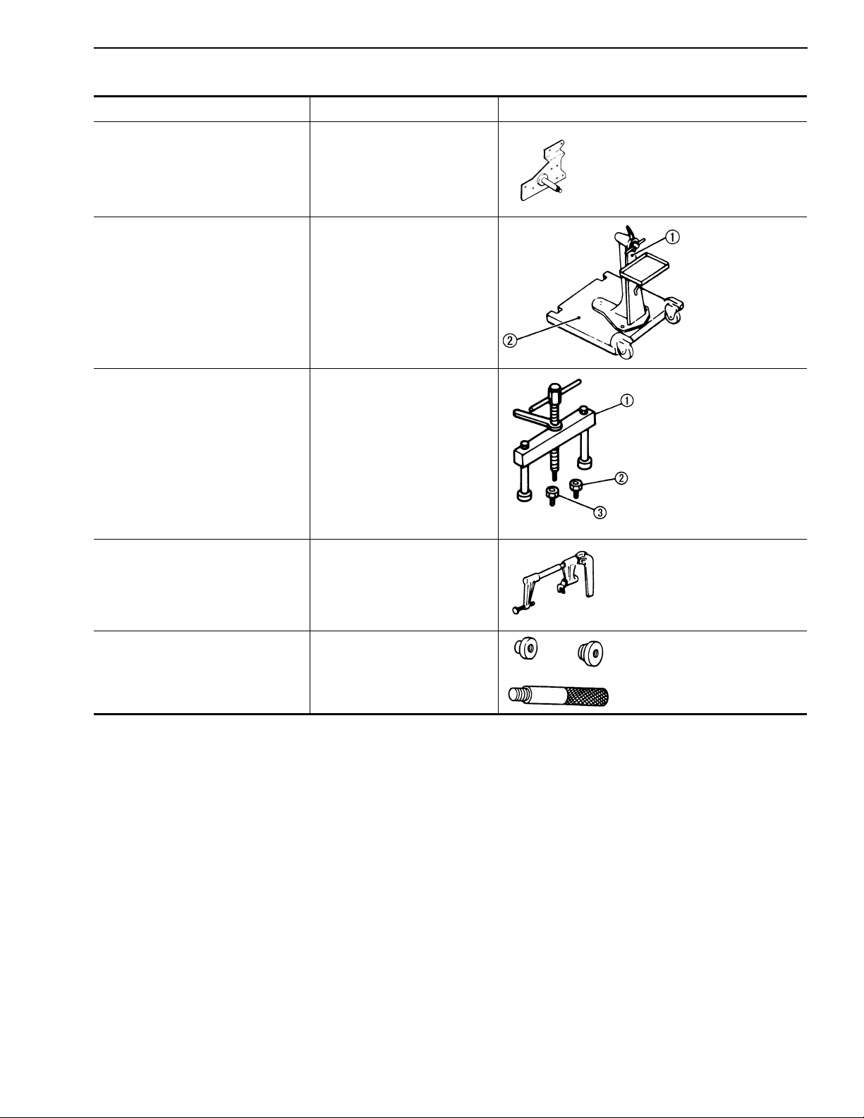
SPECIAL SERVICE TOOLS
SPECIAL SERVICE TOOLS
Tool number Tool name
ST05240001 Engine attachment
GIM0066
ST0501S000
(1) ST05011000
(2) ST05012000
KV101041S0
(1) KV10104110
(2) ST16512001
(3) ST16701001
ST12070000 Valve lifter
ST1524S000
KV10105500
ST15243000
Engine stand assembly
Engine stand
Stand
Crankshaft main bearing
Crankshaft main bearing cap puller
Ring puller
Adapter
Adapter
Front oil seal drift
Rear oil seal drift
Drift rod
GIM0067
GIM0068
GIM0069
EM-13
GIM0071
Page 73

REMOVAL AND INSTALLATION OF ENGINE
REMOVAL AND INSTALLATION OF ENGINE
CAUTION:
• Always pay attention to safety.
• Do not remove engine until exhaust system and engine
coolant have completely cooled off.
• Support the vehicle at the specified lift points.
• For operation procedure for components other than
engine, refer to appropriate sections.
Removal
[OPERATION DESCRIPTION]
• Remove engine by pulling up after removing transmission.
[PREPARATION WORK]
1. Remove radiator drain plug and drain engine coolant.
2. Remove the following parts.
• Undercover of battery
• Radiator, shroud, and radiator hose
• Engine drive belt and cooling fan
3. Disconnect accelerator cable from throttle drum and move it out
of position.
[LEFT SIDE OF ENGINE ROOM]
4. Remove air duct and air cleaner case.
5. Disconnect heated oxygen sensor harness connector and
ground (between exhaust manifold cover and body).
[RIGHT SIDE OF ENGINE ROOM]
6. Disconnect vacuum hose (for brake booster and for differential
lock) on engine side.
7. Remove fuel hose.
CAUTION:
After disconnecting hoses, plug them immediately to prevent
fuel from draining.
8. Disconnect all harness connectors on engine side, and then
move harnesses to body side.
9. Remove starter motor.
10. Remove transmission.
[REMOVAL]
11. Engage chain block hook in front/rear engine slingers and
support.
CAUTION:
Be careful not to contact hook and chain with body and piping
when engaging hook in slingers
12. Remove engine mount insulator LH/RH nuts.
13. Pull up and remove engine by adjusting the position diligently.
CAUTION:
• Make sure that all wires and piping were disconnected
while removing.
• Be careful not to contact with body side parts.
EM-14
Page 74

REMOVAL AND INSTALLATION OF ENGINE
Installation
Note the following, and install in the reverse order of removal.
• Do not allow oil to get on the engine mount insulator. Be careful
not to damage the engine mount insulator.
• Securely insert positioning stopper pin into mating side hole.
• Make sure all mount insulators are seated properly, then tighten
mount nuts and bolts.
Inspection
• Before starting engine, check amount of engine coolant, oil and
grease. Refill as necessary.
• Start engine and check for any unusual noise and vibration.
• Warm up engine, and then check engine coolant, oil and
grease, fuel, and exhaust gas for leakage.
EM-15
Page 75
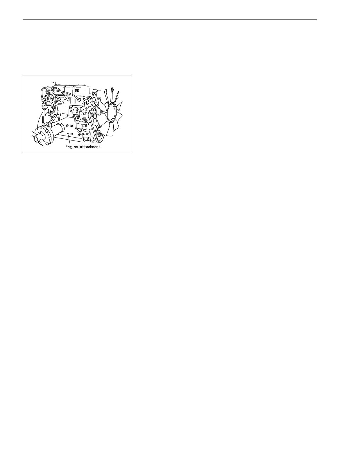
ENGINE SERVICE
ENGINE SERVICE
EMM0554
Engine Disassembly
Always use appropriate tools and ensure that no parts are damaged.
The following tasks can be performed more easily by using the
relevant engine attachment (SST) and engine stand (SST).
1. Preparation for engine disassembly
• Drain coolant and engine oil.
2. Installation of engine attachment
Remove the following parts from the cylinder block and install
the engine attachment (SST).
• Oil filter
• Engine mount bracket (RH)
• Fuel tube
• Oil pressure switch
• Release the alternator adjusting lever and remove the
alternator.
• Using some of the existing holes on the engine attachment
(SST), retain the attachment with the mounting bracket
bolts at four points at least.
3. Removal of exterior and electrical parts
Set the engine to the engine stand (SST) and remove the following parts.
• Ignition system wiring (or high-tension cords for mixer
model)
• Distributor
• Spark plug
• Oil level gauge
• Cooling fan and pulley
• Starter motor
• Clutch and flywheel
• Rear plate
•Rocker cover
• Crankshaft pulley
• Remove the oil pump and drive shaft (for mixer type, also
remove the distributor).
EM-16
Page 76

EMM0314
ENGINE SERVICE
Engine Disassembly (Cont’d)
4. Removal of manifold
• Remove the manifold and head retaining bolts.
• Remove the intake and exhaust manifold assembly.
5. Removal of rocker cover and gasket
• Remove the rocker cover retaining nuts.
• Remove rocker cover.
6. Removal of rocker shaft assembly
• Loosen the four valve rocker shaft bolts to remove the valve
rocker shaft.
• Pull off the push rod.
• Make sure to remove the push rod and other parts by
cylinder and by port (intake or exhaust), and store them in
an organized manner so that the part installation locations
are easily identifiable.
• When removing the valve rocker shaft, compress the coil
spring slightly and tie the spring with a metal wire, as
shown in the figure, before loosening the bolts. This will
facilitate the reassembly work later. Or, loosen the four
bolts evenly.
EMM0539
EMM0318
7. Removal of cylinder head assembly
• Pull off the push rod.
• Loosen the cylinder head bolts according to the following
sequence.
• Remove cylinder head.
EM-17
Page 77
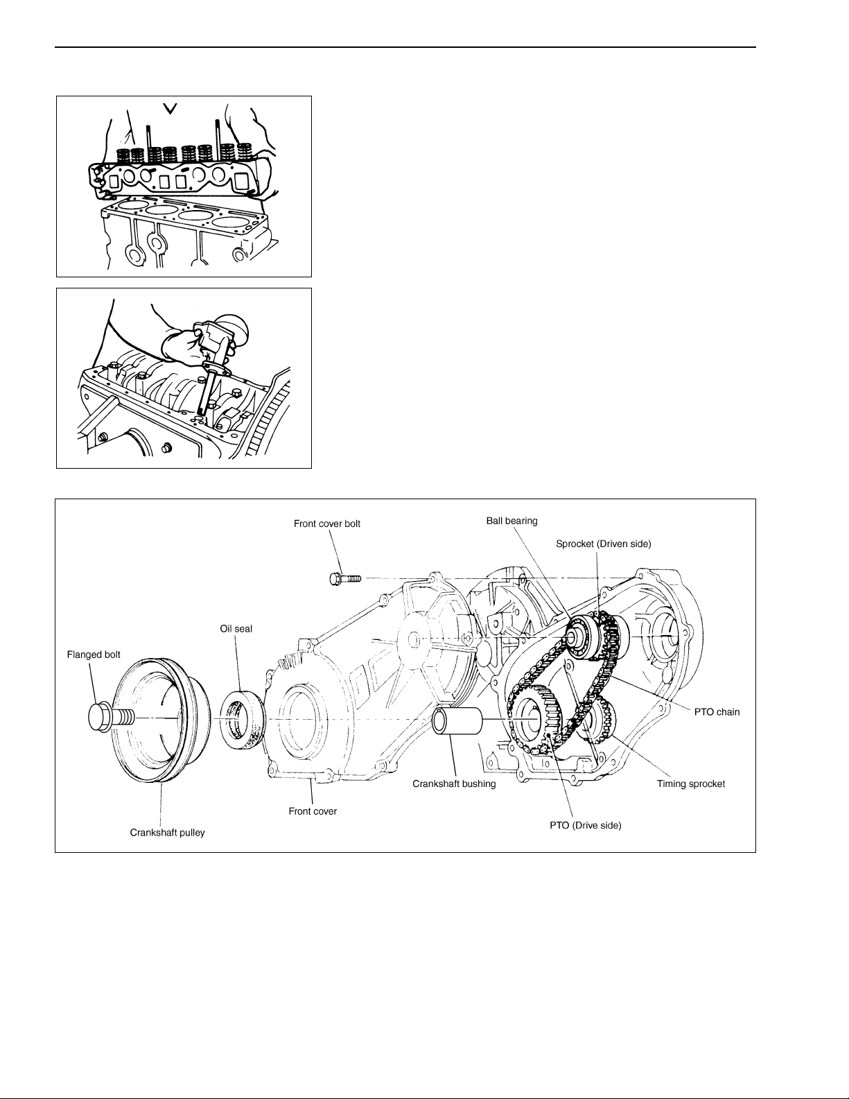
FEM008
ENGINE SERVICE
Engine Disassembly (Cont’d)
8. Remove oil pan.
Remove any sealant.
9. Remove oil pump with strainer.
FEM009
10. Disassembly of PTO device
EMM0557
• Remove flanged bolt.
• Remove crankshaft pulley.
• Remove the crankshaft bushing.
EM-18
Page 78
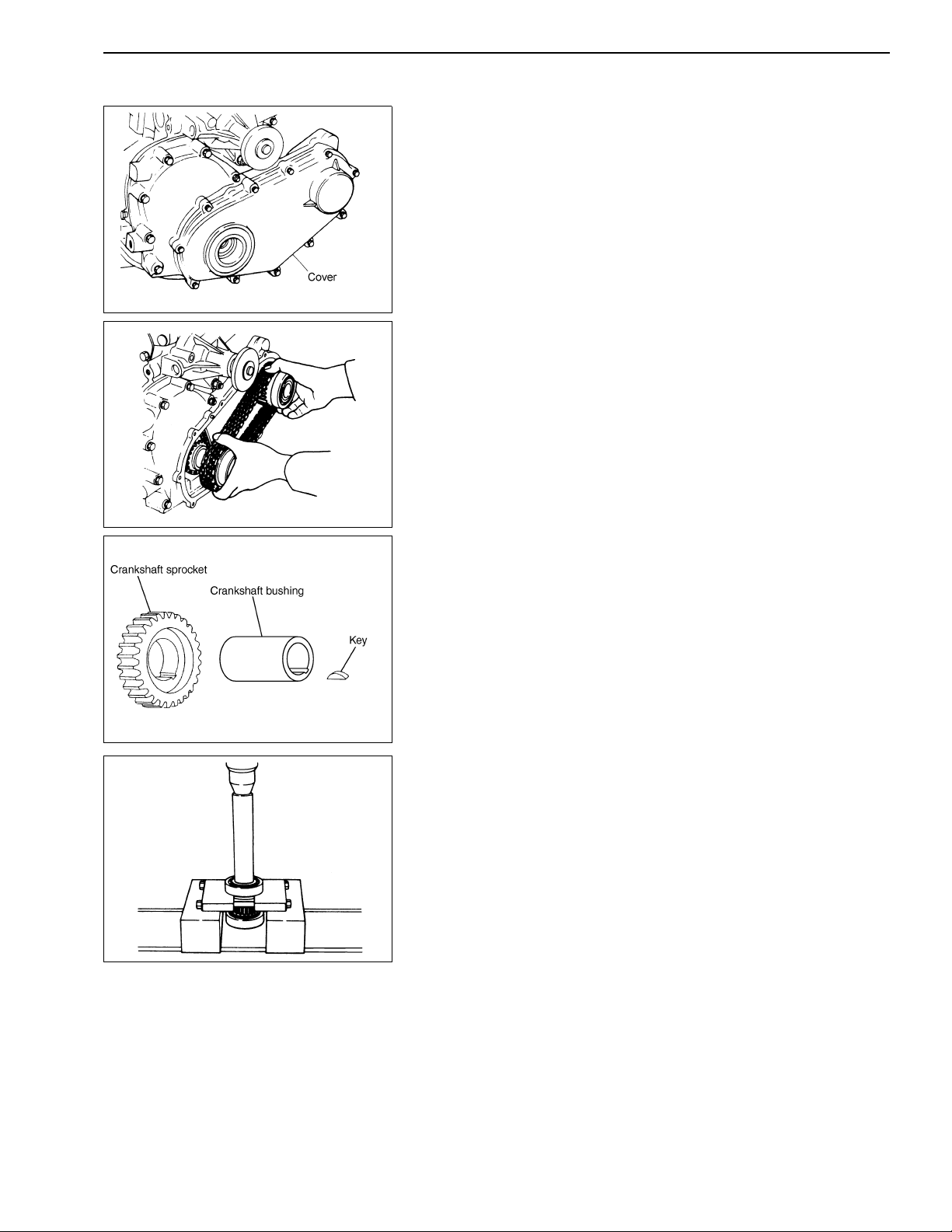
EMM0320
ENGINE SERVICE
Engine Disassembly (Cont’d)
• Remove the front cover.
• To remove the cover, remove the bolts and lightly tap on it
with a plastic hammer.
Before installing the cover, apply sealant (liquid packing) to
the mounting face.
11. Remove the PTO sprocket, PTO chain, and bearing as an
assembly from the oil pump side and the crankshaft side.
FEM012
EMM0558
FEM014
CAUTION:
Ensure that the chain is not damaged.
12. To separate the oil pressure pumpside sprocket and the
bearing, use the relevant Special Service Tool with a press.
ST3D031000 Bearing puller
ST22360002 Bearing drift
EM-19
Page 79
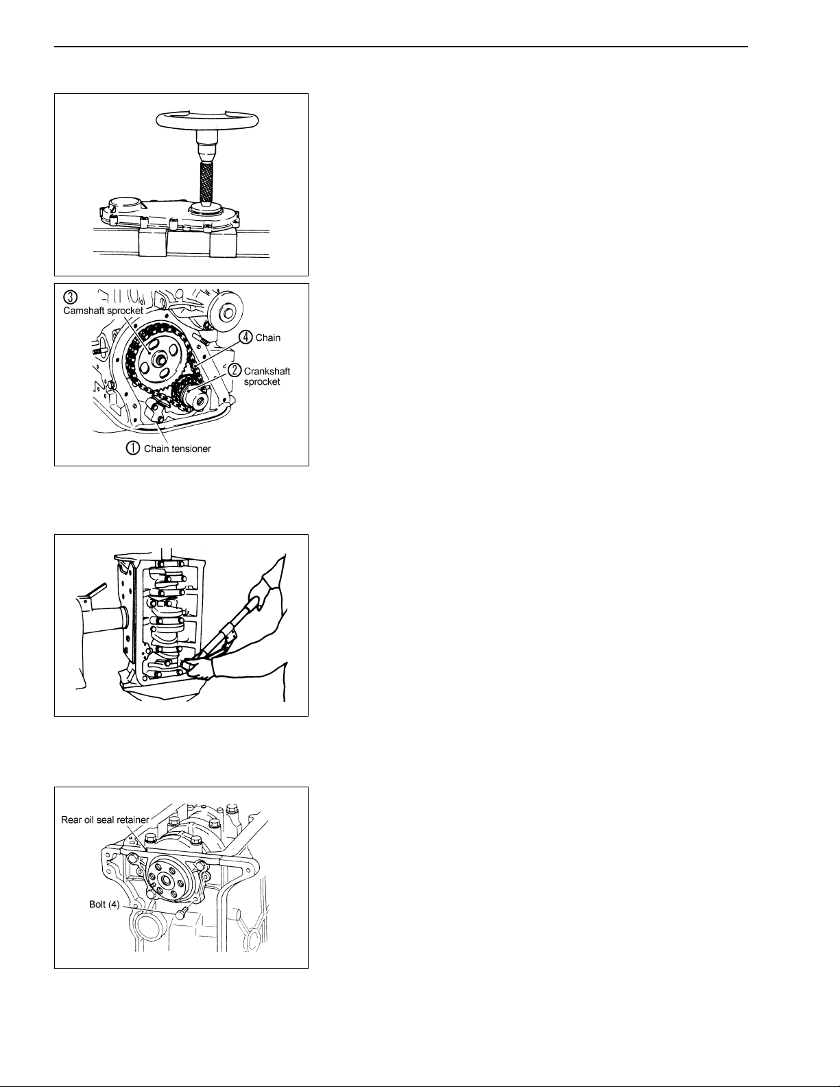
FEM015
EMM0322
ENGINE SERVICE
Engine Disassembly (Cont’d)
13. Timing chain cover
• Remove front oil seal.
Remove from the front cover using the front oil seal drift (SST).
Special Service Tools (SST): Front oil seal drift ST1524S000
Drift rod ST15243000
14. Remove timing chain cover.
15. Remove chain tensioner (1).
16. Loosen the camshaft sprocket bolts.
17. Remove the camshaft sprocket (3) and crankshaft sprocket (2)
along with the chain (4).
18. If shim(s) are attached for the crankshaft gear, also remove
them.
19. Removal of camshaft
• Remove locating plate.
• Turn over the cylinder block. Lower and pull off the valve
lifter.
• Pull off the two bolts retaining the camshaft locating plate
and remove the camshaft. Be careful not to damage the
metal faces.
Place the parts in the order of cylinder arrangement.
20. Removal of piston and connecting rod
• Remove connecting rod cap and push the piston out toward
cylinder head side with handle of a hammer. Be careful not
to drop the pistons.
• Pull the piston toward the cylinder block top deck and
tentatively assemble the rod cap to prevent incorrect
assembly.
Place the parts in the order of cylinder arrangement.
FEM017
EMM0323
CAUTION:
Store the connecting rod caps and bearings in the order of
cylinder arrangement to prevent incorrect assembly.
21. Loosen the flywheel bolts and remove the flywheel.
22. Remove rear plate.
23. Removal of crankshaft
• Remove the rear oil seal retainer.
• Remove the main bearing cap bolts. Remove the main
bearing cap by lightly tapping on it with a wooden hammer.
CAUTION:
Store the bearing bushings in an organized manner so that the
part installation locations are easily identifiable.
EM-20
Page 80
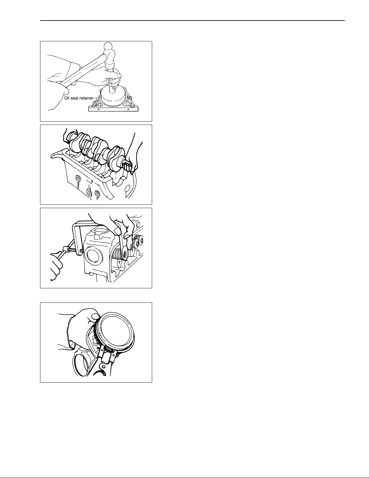
EMM0324
ENGINE SERVICE
Engine Disassembly (Cont’d)
24. Remove the oil seal from the oil seal retainer using the rear oil
seal drift (SST).
SST: KV10105500
25. Remove the crankshaft and bearing.
After removing the bearing, place the corresponding cap at a
correct position on the block side face to prevent incorrect
assembly.
FEM019
FEM020
26. Disassembly of cylinder head
• Remove valve spring using a valve lifter (SST).
SST: ST12070000
• Remove valve lipseal using a lip seal puller (SST) when
removing.
CAUTION:
Replace lip seal when removing valve. (Do not reuse.)
• Store the removed valves, valve collets, valve retainers,
and valve springs in an organized manner to identify which
part combination corresponds to which cylinder.
27. Disassembly of piston and connecting rod
• Disassemble the piston and connecting rod.
• Remove piston rings.
The oil ring is a combined type. To remove it, first remove
the upper and lower rails, and then the expander.
CAUTION:
Store the removed pistons, pins, connecting rods and bushings
in an organized manner to identify which part combination
corresponds to which cylinder.
EM102
EM-21
Page 81
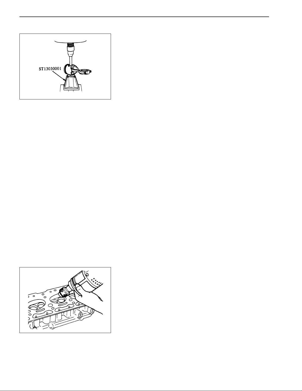
EM103
ENGINE SERVICE
Engine Disassembly (Cont’d)
28. Pull off the piston pin.
The piston pin is press-fit into the connecting rod.
To remove the piston pin, first remove the snap ring, heat the
piston to 80°C (176°F), and then pull off the piston pin by using
the piston pin press stand (SST).
CAUTION:
Store the removed pistons, piston pins, piston rings and
connecting rods in an organized manner to identify which part
combination corresponds to which cylinder.
Inspection and Correction
1. General precautions
• Inspect each part for damage, distortion, bend or excessive
play and repair/replace the part if the condition is
unallowable.
• Before cleaning the cylinder head and block, check for any
trace of water leakage.
• Completely remove any water scale, sealant, and carbon
from each part.
CAUTION:
Be careful not to damage the sliding faces when using a carbon
scraper or brush.
• After cleaning the oil passage of each part, verify that no
plugging is present by applying compressed air.
• Make sure that any parts requiring correct combination are
identified appropriately.
• For a part that is to be stored for a long time after cleaning,
make sure to apply oil to the high-finished surfaces to
prevent rust creation.
2. Intake manifold water jacket
• Also inspect the water jacket connector. Repair or replace it
if any traces of leakage are found.
• Also inspect the water hoses. If any deterioration or
damages are found, replace them. If any leakage is found
at the connections, retighten the clamps.
3. Cylinder head
REMOVING CARBONS
• Remove any carbons from the combustion chamber and
mounting faces of each cylinder. At that time, also check for
scratches and damages.
• Remove oil, scale, gasket, sealant, and carbon deposits
from surface of cylinder head using a scraper.
FEM024
CAUTION:
Do not allow gasket fragments to enter oil or engine coolant
passages.
EM-22
Page 82
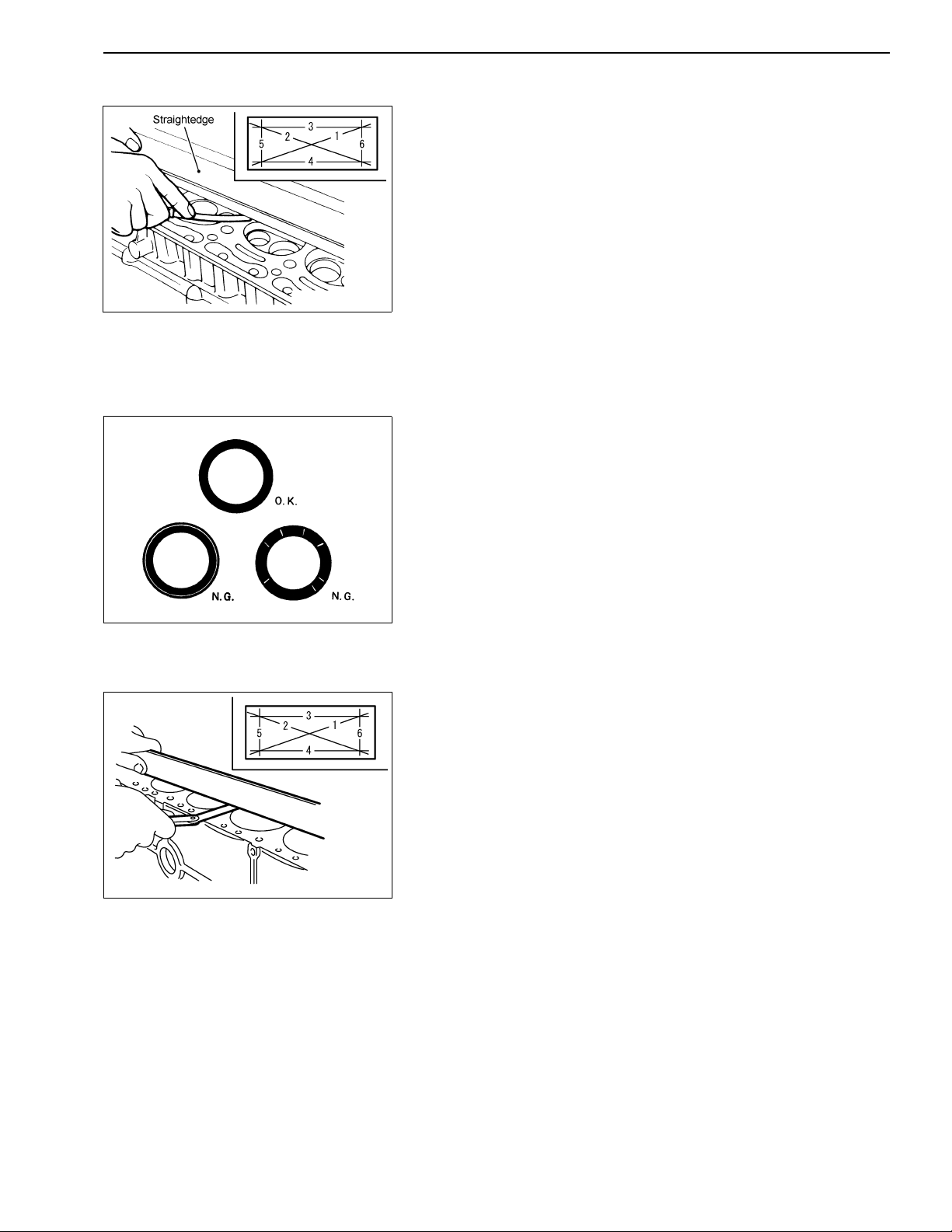
EMM0325
ENGINE SERVICE
Inspection and Correction (Cont’d)
MEASURING CYLINDER HEAD DISTORTION
• Visually check for any cracks and damages.
• Measure distortion at six points on the head bottom face. If the
measured distortion exceeds the specified limit, correct the
head bottom face with a surface grinder or an equivalent tool, or
replace the head.
Surface flatness 0.1 mm (0.004 in) or less
Grinding limit 0.2 mm (0.008 in) or less
VALVE SEAT CONTACT
• This inspection must be done after ensuring that the dimensions
of the valve guide and the valve are within the standard.
• Check valve contact by applying DICATOL PL-1 to valve seat
contact surface.
• Make sure that areas around all connect surfaces are
connected.
• If seating condition is not correct, reseat the valve and check
again.
If seating condition cannot be corrected by reseating, replace
cylinder head.
EMV0149D
EMM0327
4. Cylinder block
Measure distortion of the cylinder block top face in the longitudinal and lateral directions.
Measuring cylinder block distortion.
• Remove any foreign material deposits such as carbon from
the cylinder block.
• (Use a straight ruler and filler gauge for distortion
measurement)
• Visually check for any cracks and damages.
• Measure distortion at six points on the head top face . If the
measured distortion exceeds the specified limit, correct the
head top face with a surface grinder or an equivalent tool,
or replace the head.
EM-23
Page 83
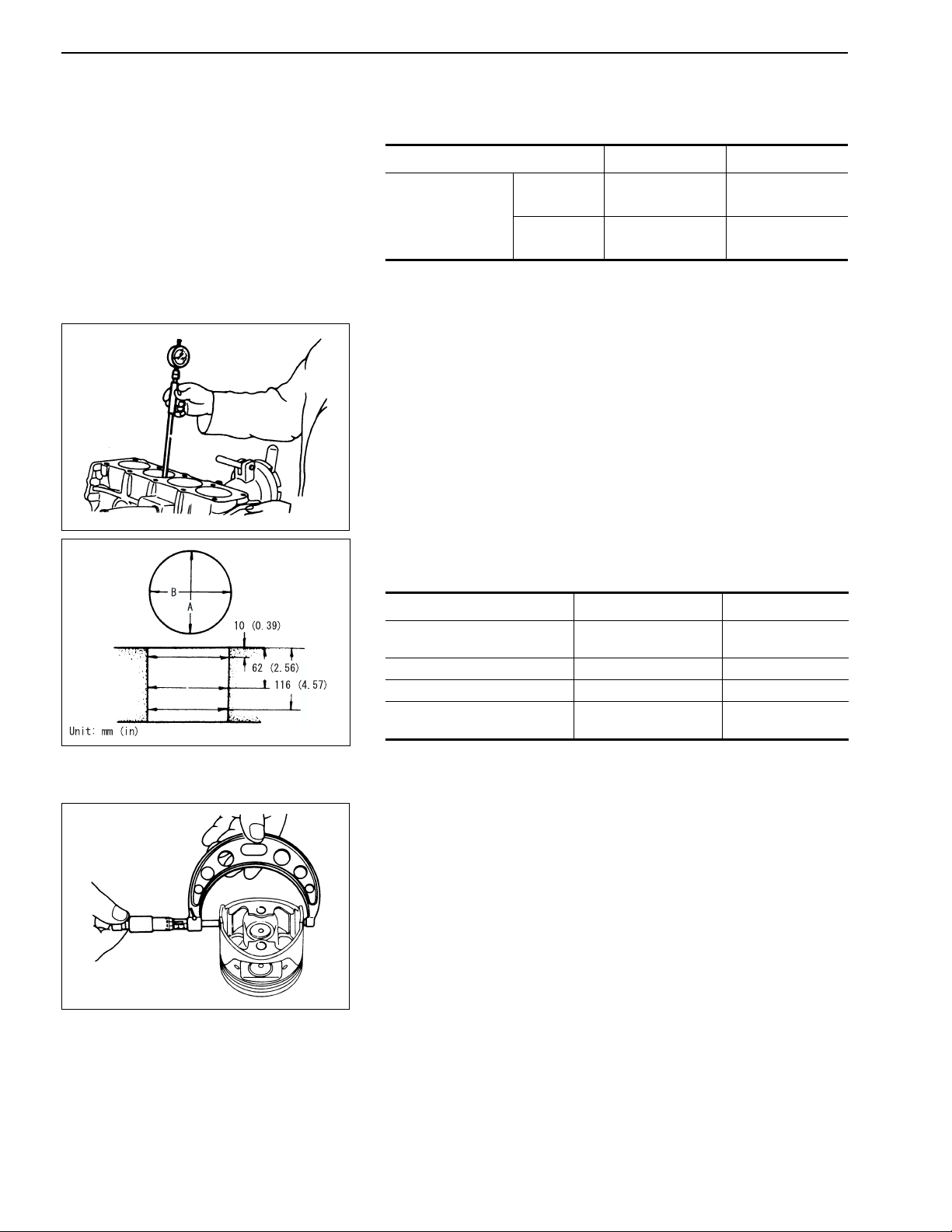
ENGINE SERVICE
Inspection and Correction (Cont’d)
Distortion limit: 0.1 mm (0.004 in)
Standard Repair limit
Longitudinal
mm (in)
Cylinder block face
Lateral
mm (in)
5. Measuring cylinder bore
• Take the following measurements for the directions A and B
at three levels using a cylinder bore gauge.
Determine the grade based on the measurement at a point located
65 mm from the top deck in the thrust direction.
0.05 (0.0020) 0.10 (0.0039)
0.02 (0.0008) 0.04 (0.0016)
EM124
EMM0540
Max. difference between A and B Roundness
Max. difference among three levels Taper
Unit: mm (in)
Standard Wear limit
Cylinder bore inner diameter 89.0 - 89.05 (3.5039 -
Roundness - 0.2 (0.008)
Taper - 0.2 (0.008)
Difference in inner diameter
between respective cylinders
3.5059)
- 0.2 (0.008)
75.7 (2.980)
89.20 (3.5118)
6. Balling and horning
(1) Select an appropriate oversize piston according to the wear of
the cylinder inner surface.
Measure the piston skirt diameter. Bore the cylinder to a diameter 0.02 mm (0.0008 in) larger than the measurement.
EM126
EM-24
Page 84
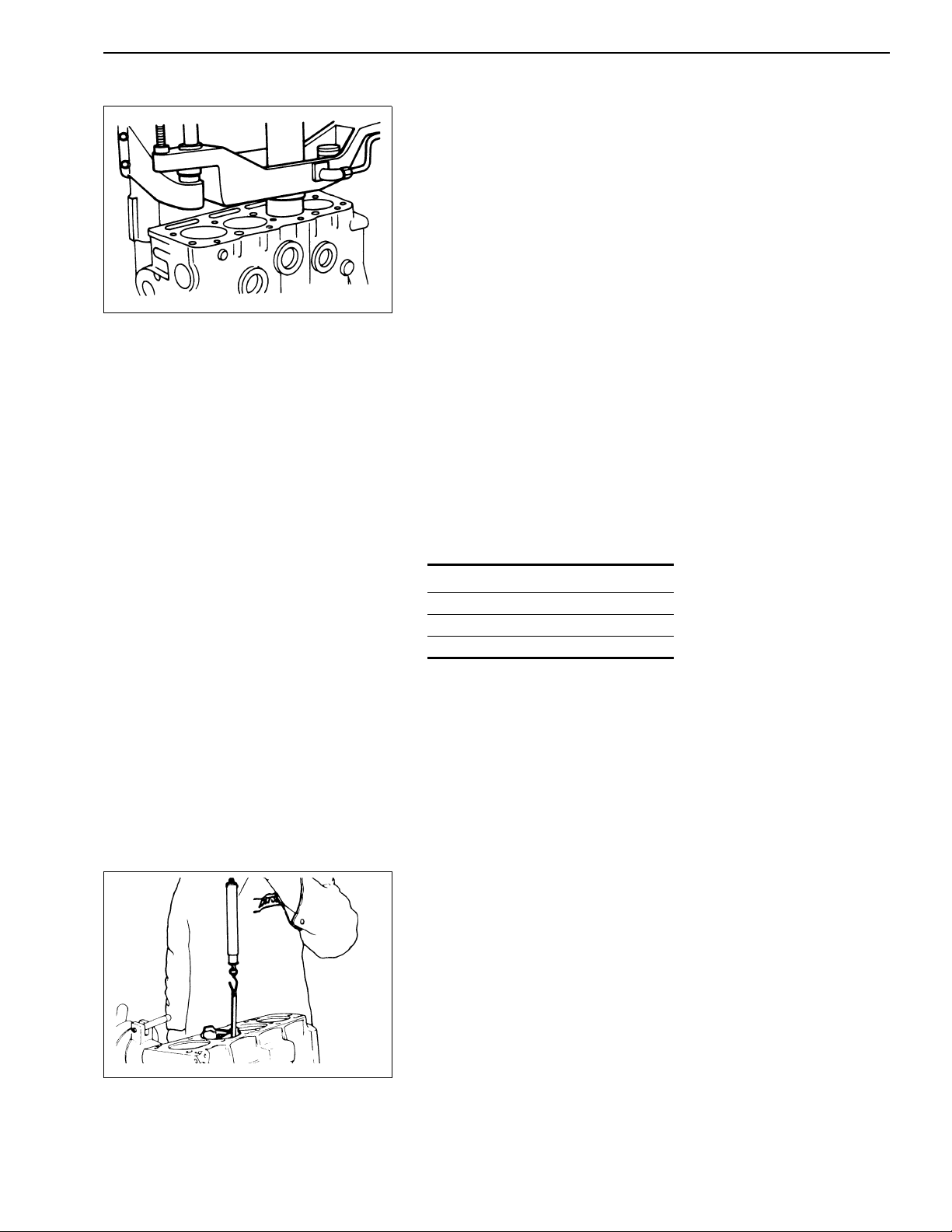
FEM035
ENGINE SERVICE
Inspection and Correction (Cont’d)
• Ensure that the piston-to-cylinder clearance is between
0.025 and 0.045 (0.0010 and 0.0018 in). Make sure to
perform measurement in ordinary temperature. If even one
cylinder requires boring, all cylinders must be bored at
once.
(2) Calculating cylinder inner diameter
• Measure the skirt diameter (dimension H) of the oversize
piston.
• Based on the dimension H of the piston, determine the
cylinder boring diameter.
Boring diameter: R = H + C – M
Boring margin: M = 0.02 mm
Piston-to-cylinder clearance
: C = 0.025 to 0.045 mm (20°C)
∴R= H + (0.005 to 0.025) mm
• Bore the cylinder to the dimension R.
Piston service part list
Oversize
STD
0.50 (0.0197)
1.00 (0.0394)
Unit: mm (in)
(3) Boring precautions
• Make sure to bore the cylinder step-by-step with the boring
depth of each step limited to 0.05 mm (0.0020 in).
• Notice that the cylinder inner diameter is affected by the
cutting heat.
• To prevent deformation due to cutting heat, bore the
cylinders in the order of No. 2, No. 4, No. 1 and No. 3.
• Apply an appropriate mark to each piston so that which
piston is for which cylinder is easily identifiable.
(4) After horning, measure the taper and roundness of the bore.
(5) Measuring piston-to-cylinder clearance
Pull off the piston pin from the piston and put the piston into the
cylinder upside down. Insert a filler gauge of 0.04 mm (0.0016
in) in the piston-to-cylinder clearance from the piston sliding
side and pull the filler gauge with a spring scale. If the spring
scale reads 0.5 kg to 1.5 kg (1.1 to 3.3 lb), the clearance is normal.
EMM0329
EM-25
Page 85
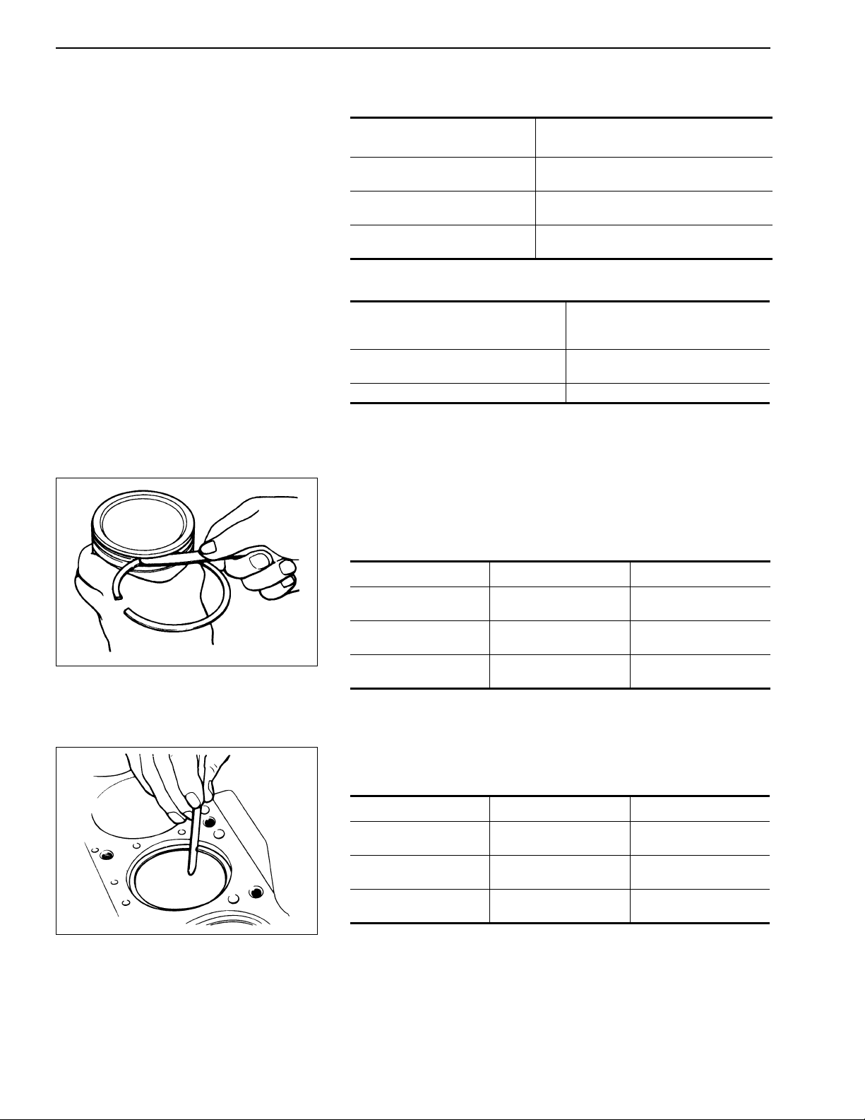
ENGINE SERVICE
Inspection and Correction (Cont’d)
Oversize piston
EM423
Piston size
STD 88.965 - 89.015
0.50 (0.0197) OS 89.465 - 89.515
1.00 (0.0394) OS 89.965 - 90.015
Diameter
mm (in)
(3.5026 - 3.5045)
(3.5222 - 3.5242)
(3.5419 - 3.5439)
Standard measurements for piston and cylinder
Specified clearance mm (in) 0.025 - 0.045
Filler gauge N (kg, lb) Drawing force 4.9 to 14.7
Filler gauge in use Thickness mm (in) 0.04 (0.0016)
(0.0010 - 0.0018)
[20°C (68°F)]
(0.5 - 1.5, 1.1 - 3.3)
7. Measuring piston wear
• Inspect the piston sliding face. Replace it if significant
sticking damage or wear is observed.
• Measuring piston ring-to-groove clearance
Measure the clearance between the piston ring groove and
the piston ring. If excessive wear is observed, replace the
piston ring along with the piston.
Standard Limit
Top 0.045 - 0.080
(0.0018 - 0.0031)
Second 0.030 - 0.070
(0.0012 - 0.0028)
Oil 0.065 - 0.135
(0.0026 - 0.0053)
0.1
(0.004)
0.1
(0.004)
—
Unit: mm (in)
EM542
8. Piston ring
• Measuring piston ring closed gap
• Put the piston ring into the cylinder bore and measure the
ring closed gap.
Standard
Top 0.28 - 0.43
(0.0110 - 0.0169)
Second 0.45 - 0.60
(0.0177 - 0.0236)
Combined rail 0.20 - 0.60
(0.0079 - 0.0236)
limit
1.0
(0.039)
1.0
(0.039)
1.0
(0.039)
Measure the end gap of the piston ring with a feeler gauge. If
the gap exceeds 1 mm, replace the piston ring. If the gap is
0.15 mm or less, correct the ring ends with an oil stone or
replace the piston ring.
EM-26
Unit: mm (in)
Page 86
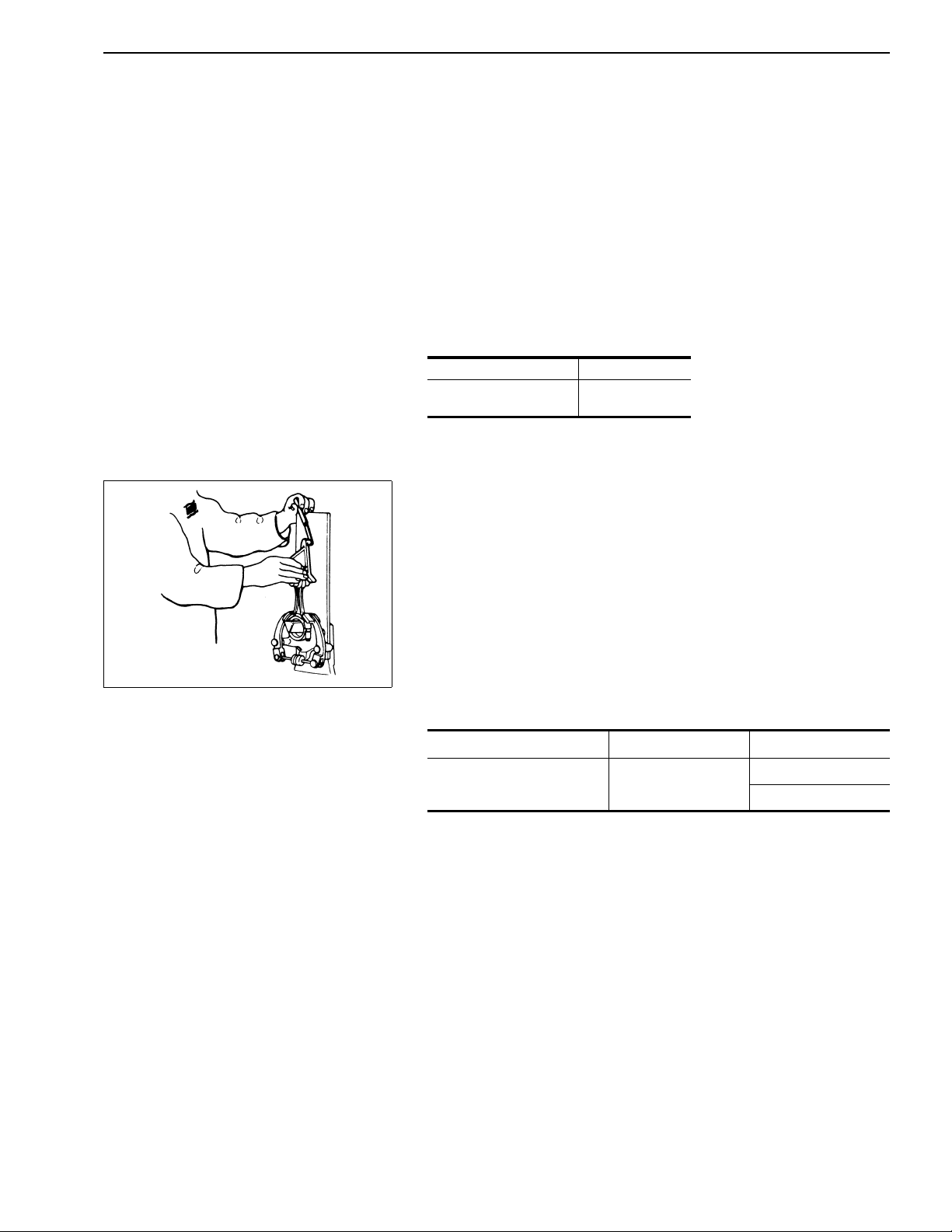
ENGINE SERVICE
Inspection and Correction (Cont’d)
CAUTION:
Always measure the ring gap near the bottom of the cylinder
where the wear is relatively small when replacing the piston
ring without correcting the cylinder bore.
9. Piston pin
FITTING PISTON PIN TO PISTON
• In ordinary temperatures, the piston pin should rotate when
turned by hand or the pin should go smoothly when
inserted.
• If the piston pin behavior is unusual, replace the piston and
piston assembly.
Unit : mm (in)
Engine type K21, K25
Piston pin outer diameter 19.993 - 19.998
(0.7871 - 0.7873)
10. Connecting rod
MEASURING BEND, TWIST
• Measure the bend and twist using a connecting rod aligner.
If the measured bend or twist is excessive, replace the
component.
Usable limit: Bend 0.05 mm (0.0020 in)
[per 100 mm (3.94 in)]
Twist 0.05 mm (0.0020 in)
[per 100 mm (3.94 in)]
EM133
CAUTION:
The center distance between both end holes must be
143.97 - 144.03 mm (5.6681 - 5.6705 in) (K25)
152.47 - 152.53 mm (6.0027 - 6.0051 in) (K21)
Unit : mm (in)
Standard Repair limit
Bend Twist Parallelism
[per 100 mm (3.94 in)]
for every 100 mm (3.94 in)
0.025 (0.0010) (B) 0.05 (0.0020)
(T) 0.05 (0.0020)
11. Connecting rod weight
WEIGHT ADJUSTMENT
• When replacing the connecting rod assembly, ensure that
the maximum difference in the connecting rod assembly
weight between any two cylinders does not exceed 4 g
(0.14 oz).
EM-27
Page 87
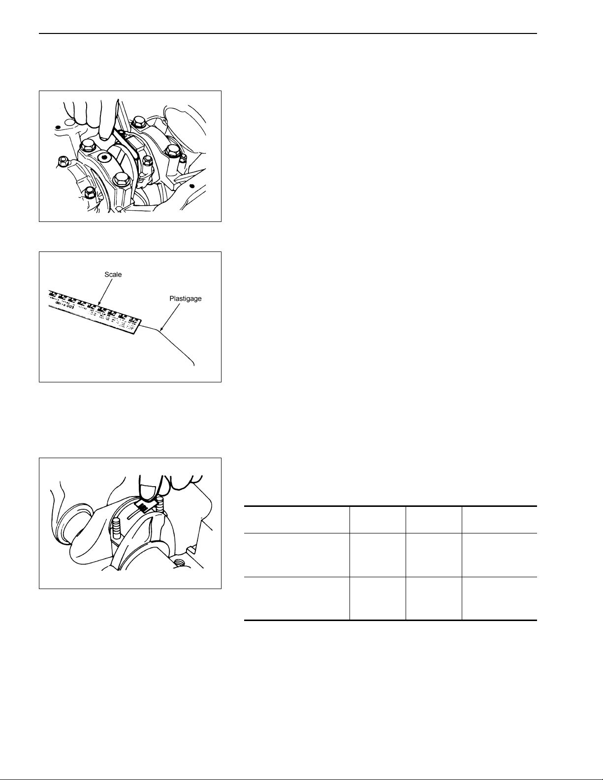
ENGINE SERVICE
Inspection and Correction (Cont’d)
MEASURING CONNECTING ROD THRUST CLEARANCE
• Measure the thrust clearance using a feeler gauge.
• Measure the connecting rod side clearance. If the
clearance exceeds the limit, replace the connecting rod.
Standard clearance: 0.2 - 0.3 mm (0.008 - 0.012 in)
Max. clearance: 0.4 mm (0.016 in)
EM134
EMM0330
FEM036
12. Connecting rod and bushings
• Check the bushings for bend, melting, or tearing and
replace them if damaged.
• Measure the oil clearance using a plastigage.
MEASURING OIL CLEARANCE
• The following paragraphs describe how to use a plastigage.
a. Remove any oil and dust from the bearing inner/outer
faces and journal faces. Cut off the plastigage to a
length slightly shorter than the bearing width. Place
the cut plastigage on the journal face so as not to
cover any oil holes.
b. Assemble the bearing cap and tighten it to the
specified torque.
CAUTION:
Do not turn the crankshaft while the plastigage is in the
bearing.
c. Remove the cap and read the plastigage width using
the scale printed on the bag.
d. If the clearance exceeds the limit, use an undersize
bearing. At that time, grind the journal or pin.
Standard
Items
Main bearing
Connecting rod bearing
Oil clearance
Standard
0.02 - 0.073
(0.0008 -
0.0029)
0.032 - 0.066
(0.0013 -
0.0026)
Oil clearance
Limit
0.1
(0.004)
0.1
(0.004)
Unit: mm (in)
Cap tightening
torque
Lubricated
83.4 - 93.2N•m
(8.51 - 9.51kg-m,
62 - 69 ft-lb)
Lubricated
31.4 - 37.3N•m
(3.2 - 3.81 kg-m,
23 - 28 ft-lb)
• If the oil clearance exceeds the limit, grind the journal or pin
with a surface grinder and use an undersize bearing.
EM-28
Page 88
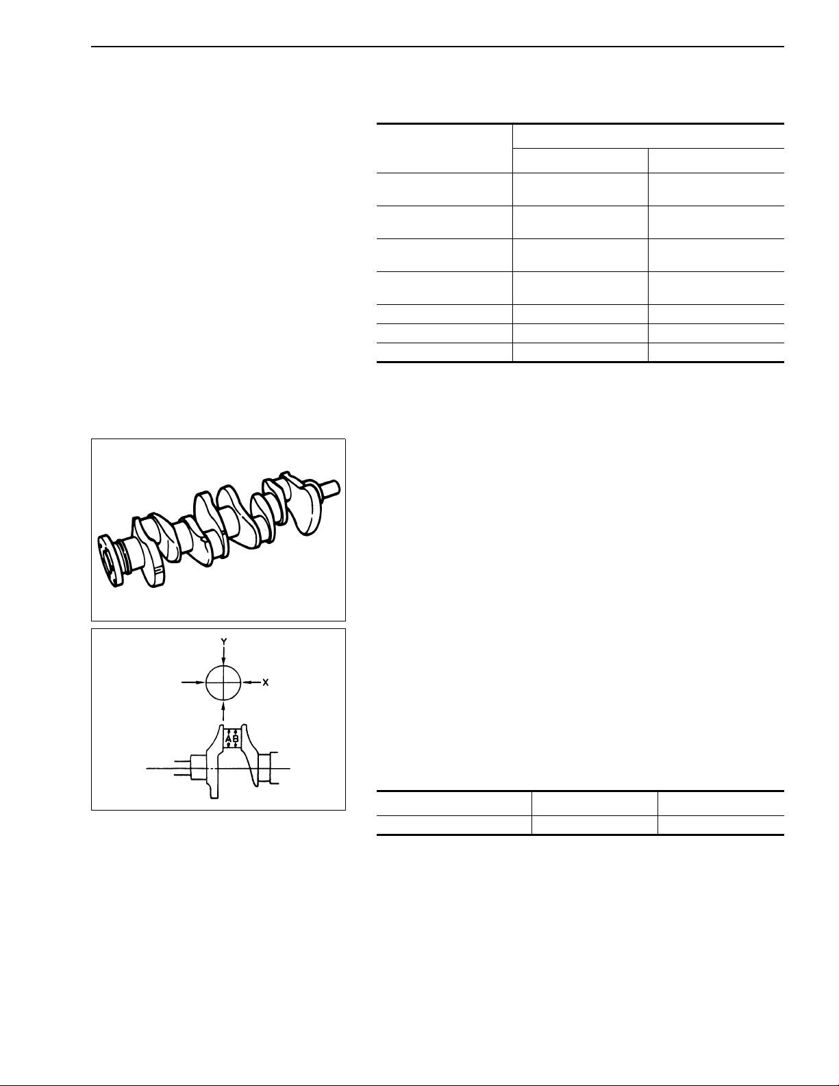
ENGINE SERVICE
Inspection and Correction (Cont’d)
Undersize bearing list Unit: mm (in)
Main bearing
STD STD 44.974 - 44.96
0.02 (0.0008) 0.12 (0.0047) 44.854 - 44.89
0.25 (0.0098) 0.25 (0.0098) 44.724 - 44.71
0.50 (0.0197)
0.75 (0.0295)
1.00 (0.0394)
13. Crankshaft and bearing
CRANKSHAFT INSPECTION
• Inspect the journal and pin for damage or wear and replace
them as necessary.
Connecting rod bearing
Pin diameter
(1.7706 - 1.7701)
0.08 (0.0031) 44.894 - 44.8
(0.1927 - 1.7638)
(1.7659 - 1.7673)
(1.7608 - 1.7602)
FEM037
EMM0331
To determine the diameter, measure the journal or pin at a
total of four points using a micrometer.
Roundness and taper of journal and pin:
Limit 0.03 mm (0.0012 in)
CAUTION:
The roundness is represented by the difference between the
dimensions X and Y in the left figure.
The taper is represented by the difference between the
dimensions A and B in the left figure.
Standard Repair limit Limit
Roundness and taper mm (in) 0.01 (0.0004) 0.03 (0.0012)
EM-29
Page 89
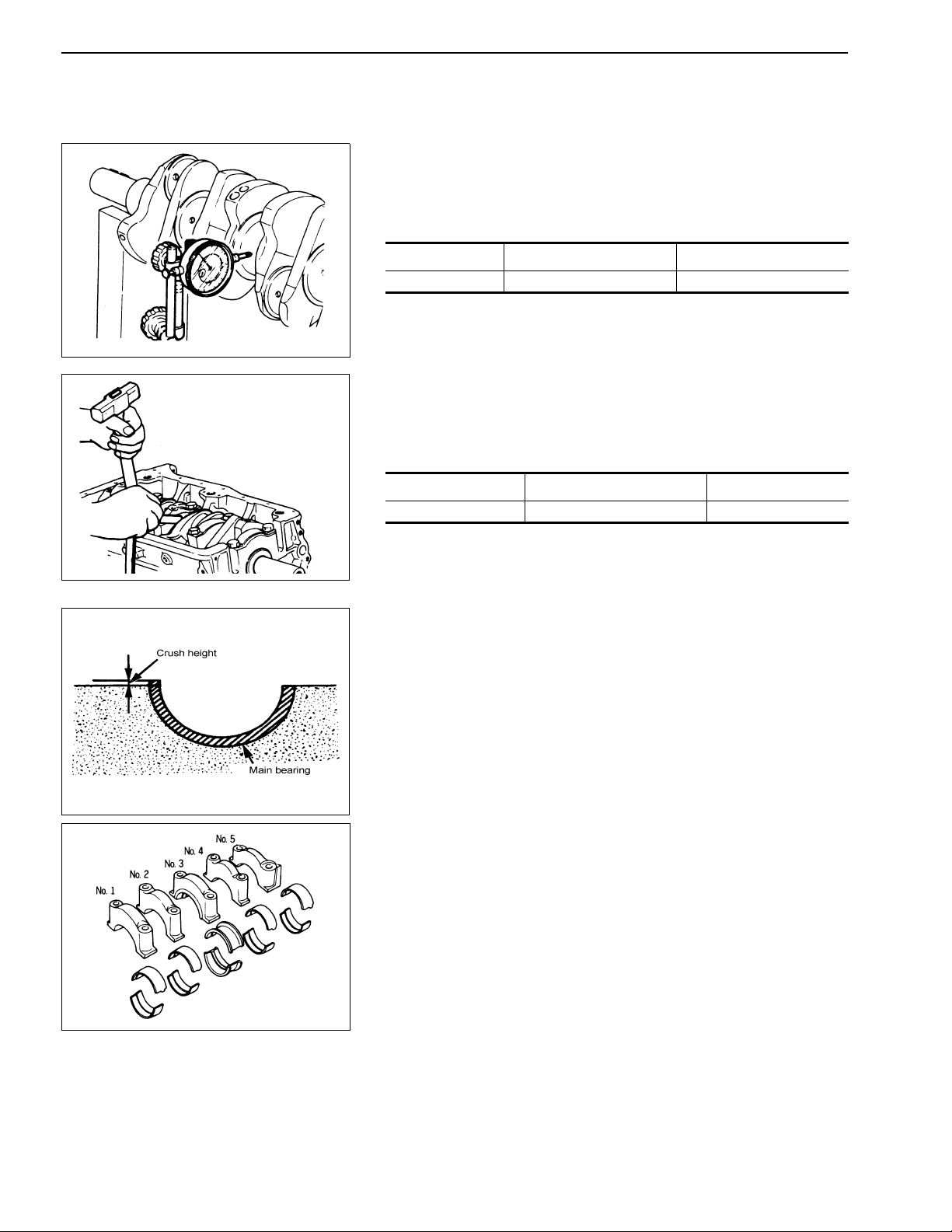
EM137
ENGINE SERVICE
Inspection and Correction (Cont’d)
MEASURING BEND
• Apply the probe of a dial gauge to the center journal and
take a reading while turning the crankshaft. Determine half
of the reading as the bend. If the bend exceeds the
specified limit, replace the crankshaft.
Bend limit: 0.05 mm (0.0020 in)
Standard mm (in) Usable limit mm (in)
Crankshaft bend 0.02 (0.0008) 0.05 (0.0020)
MEASURING CRANKSHAFT END PLAY
• Tighten to the specified torque. After that, measure end
play.
• Assemble the crankshaft and measure the end play.
• If the end play exceeds the limit, replace the main bearing
center bushing.
Measuring main bearing end play
Standard Limit
End play mm (in) 0.05 - 0.18 (0.0020 - 0.0071) 0.2 (0.0079)
EM138
EMA0558D
EMM0332
MAIN BEARING CRUSH HEIGHT
• With main bearing installed, tighten bearing cap to the
specified torque. Remove bearing cap and make sure that
the main bearing edges protrude.
Standard: There must be crush height
CRANKSHAFT MAIN BEARING
• Inspect the main bearing bushing.
• As shown below, the main bearing bushings in use are
classified in two types.
Nos. 1, 2, 4 and 5 are common.
No.3 (center) is provided with a thrust bushing.
Check the bearing for scratch, metal fatigue, peeling or bend
and replace the upper and lower bearings together as necessary.
EM-30
Page 90
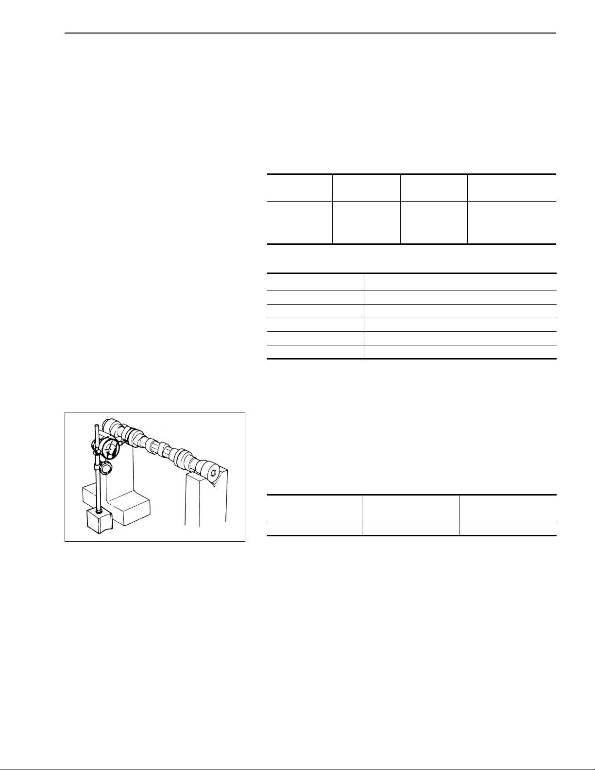
ENGINE SERVICE
Inspection and Correction (Cont’d)
MAIN BEARING CAP AND BEARING
Measuring oil clearance
(1) Remove the cap and read the plastigage width using the scale
printed on the bag.
(2) If the clearance exceeds the limit, use an undersize bearing. At
that time, grind the journal or pin.
Standard
Items
Main bearing 0.02 - 0.06
Oil clearance
Standard
(0.0008 - 0.0024)
Oil clearance
Limit
0.1
(0.004)
Cap tightening torque
Lubricated
83.4 - 93.2N•m
(8.51 - 9.51 kg-m,
61.6 - 68.8 ft-lb)
Main bearing specifications
Undersize mm (in) Crankshaft journal diameter mm (in)
0.02 (0.0008) 62.922 - 62.935 (2.4772 - 2.4778)
0.25 (0.0098) 62.692 - 62.705 (2.4682 - 2.4687)
0.50 (0.0197) 62.422 - 62.455 (2.4576 - 2.4589)
0.75 (0.0295) 62.192 - 62.205 (2.4485 - 2.4490)
1.00 (0.0394) 61.942 - 61.955 (2.4387 - 2.4392)
14. Camshaft
INSPECTION OF CAMSHAFT BEND
• Apply the probe of a dial gauge to the center journal and
measure the fluctuation while turning the camshaft.
Determine half of the reading as the camshaft bend.
Bend limit: 0.05 mm (0.0020 in)
• Replace if necessary.
Unit: mm (in)
EM122
Measuring camshaft bend
Standard (Shall not
exceed the value)
Camshaft bend mm (in) 0.02 (0.0008) 0.05 (0.0020)
Usable limit
EM-31
Page 91
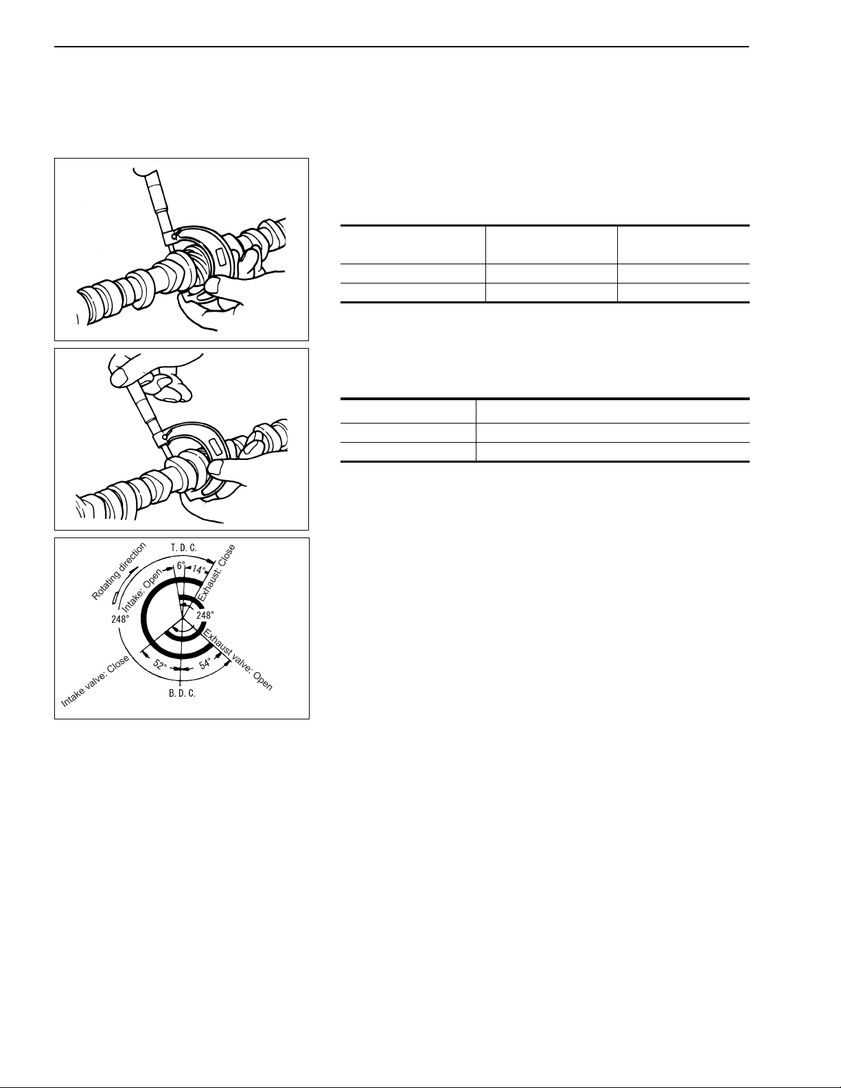
ENGINE SERVICE
Inspection and Correction (Cont’d)
CAMSHAFT JOURNAL INSPECTION
• Inspect the camshaft journal and replace it if any damage
or uneven wear is observed.
• If the wear is found to exceed the limit by measurement
with a micrometer, replace the camshaft.
Camshaft journal inspection
Camshaft journal
Taper Out-of-round mm (in) 0.01(0.0004) 0.03 (0.0012)
Journal wear mm (in) 0.05 (0.0020)
Standard (Shall not
exceed the value)
Usable limit
FEM039
FEM040
EMM0333
MEASURING CAMSHAFT HEIGHT
• Measure the camshaft height by applying calipers to the
camshaft nose.
Unit: mm (in)
Camshaft height
Standard Intake/exhaust 36.750 - 36.800 (1.4468 - 1.4488)
Usable limit 36.5 (1.437)
• Inspect the oil pump and distributor drive gear. If excessive
wear or damage is observed, replace the camshaft.
VALVE TIMING
The figure on the left is applicable to all cylinders.
If any of the valves deviate from the specifications, the camshaft
ridges may be worn out or damaged. The camshaft must be
replaced.
Camshaft bushing inspection
• Check for bend, melting, uneven contact or peeling.
• If any damage is found, replace the camshaft bushing.
Measuring camshaft journal clearance
EM-32
Page 92
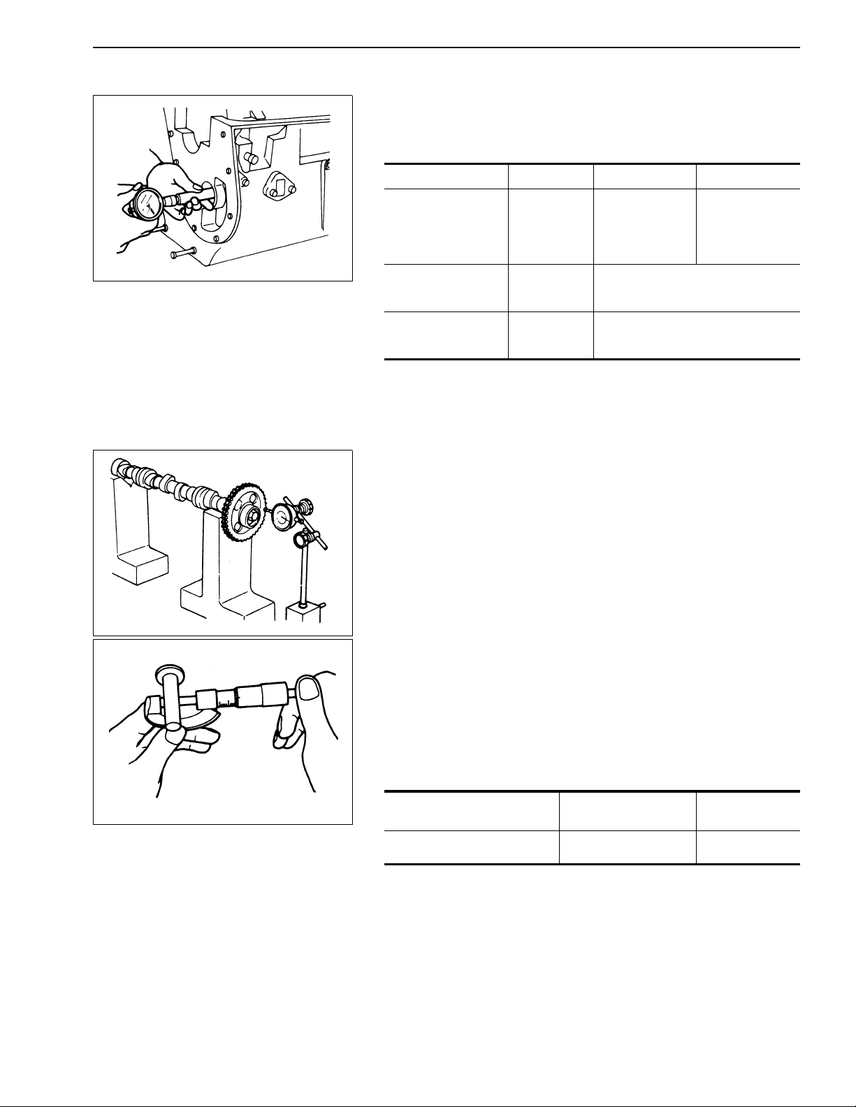
FEM041
ENGINE SERVICE
Inspection and Correction (Cont’d)
• Measure the inner diameter of the camshaft bushing and
the outer diameter of the camshaft journal. If any nonstandard condition is found, replace the camshaft bushing.
Journal No. Standard Usable limit
Clearance #1
#3
#2
Bushing inner diameter #1
#2
#3
Journal outer diameter #1
#2
#3
• When installing a new camshaft bushing, always align the
oil holes correctly.
15. Timing sprocket
• Check camshaft gear surface for flatness.
• Place the camshaft with camshaft sprocket on a V block
and measure the sprocket runout. If the deflection exceeds
0.1 mm, repair or replace the camshaft. Also inspect the
gear teeth and bosses. If any excessive wear or damage is
observed, replace the camshaft.
16. Front cover and timing chain housing
• Inspect the housing mounting faces and oil seal. If any
excessive damage is observed, replace the relevant
component(s).
0.025 - 0.051
(0.0010 - 0.0020)
0.038 - 0.064
(0.0015 - 0.0025)
45.472 - 45.485 (1.7902 - 1.9707)
43.948 - 43.961 (1.7302 - 1.7307)
41.256 - 41.269 (1.6242 - 1.6248)
45.434 - 45.447 (1.7887 - 1.7892)
43.897 - 43.910 (1.7282 - 1.7287)
41.218 - 41.231 (1.6228 - 1.6233)
Unit: mm (in)
0.1
(0.004)
0.15
(0.0059)
EM148
FEM042
17. Valve lifter
• Inspect the contact face between the valve lifter body and
camshaft. If excessive wear, damage or melting is
observed, replace the component. Also inspect the
installation status to the cylinder block and replace the
component.
• The valve lifter, if correctly installed and lubricated, should
seat into the hole slowly by its weight.
Measuring valve lifter
Valve lifter and cylinder block hole
Clearance mm (in)
Standard (Shall not
deviate from the range)
0.016 - 0.052
(0.0006 - 0.0020)
Repair limit
0.1(0.0039)
EM-33
Page 93
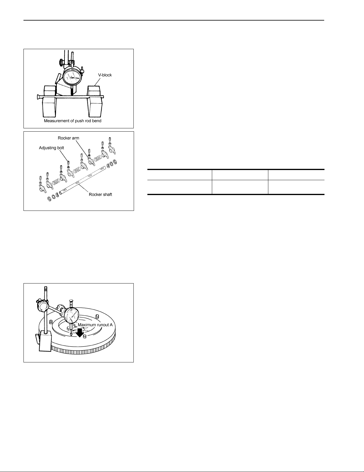
EMM0334
ENGINE SERVICE
Inspection and Correction (Cont’d)
18. Push rod
• Inspect the push rod and replace it if excessive wear, twist
or damage is observed. If a bend of 0.05 mm (0.0020 in) or
more is present, repair or replace the push rod.
19. Rocker shaft
• Check the rocker shaft for wear, damage or bend and
replace it if wear of 0.05 mm (0.0020 in) or more is
observed.
20. Rocker arm and adjusting bolt
• Inspect the valve stem-to-rocker shaft contact face of the
rocker arm and adjusting bolt. If excessive wear is found or
the rocker shaft clearance exceeds the specified limit,
replace the rocker arm (adjusting bolt).
Standard Repair limit
Rock arm/shaft
Clearance mm (in)
0.020 - 0.054
(0.0008 - 0.0021)
0.1 (0.0039)
EMM0335
EM156
21. Flywheel
• Inspect the flywheel sliding face and the ring gear teeth.
• If excessive damage or wear is observed, repair or replace
the relevant component.
• If the wear of the flywheel ring gear is relatively small,
reuse the ring gear by shifting the installation position by 45
degrees.
To install a new ring gear, heat it to 180°C (356°F) and use
a compression fitting method.
MEASURING FLATNESS
• Measure the flatness while turning the crankshaft using a
dial gauge.
• The flatness limit A is the maximum allowable flatness
measured vertically to the flywheel clutch sliding face.
Flywheel flatness limit
A: 0.1 mm (0.004 in) or less
EM-34
Page 94
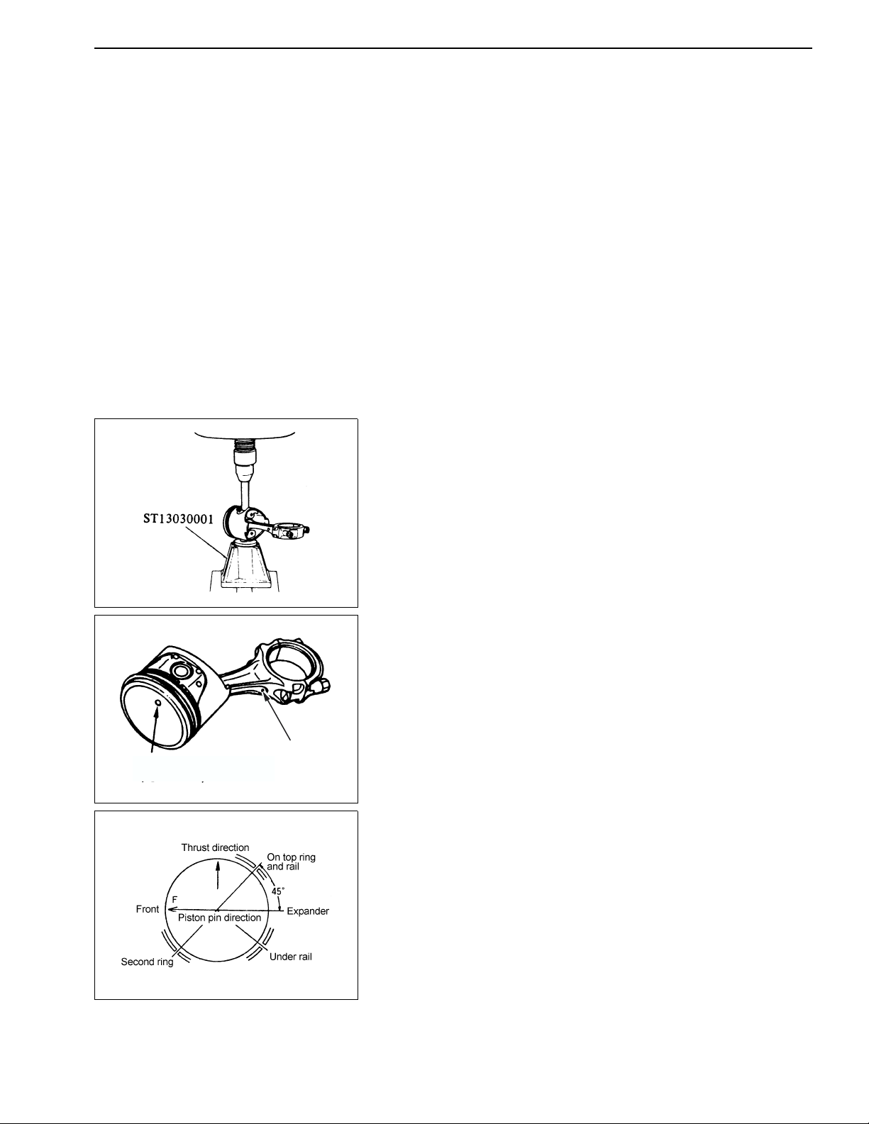
ENGINE SERVICE
Engine Assembly
1. General assembly precautions
• Apply an adequate amount of oil to the sliding faces.
• Clean the part completely. In particular, ensure that no oil
passages are plugged.
• As a rule, replace all gaskets, packing and oil seals with
new ones.
• Always replace the lock plates.
• Always follow the instructions about the tightening torque
and tightening order. While tightening, monitor the
clearance at each critical point.
• Always install the nuts, bolts and washers to their original
positions.
• For sealing, use liquid packing as necessary. Make sure to
apply liquid packing if so instructed.
• Always keep the tools and work benches clean from dust,
dirt and oil/greases.
2. Assemble the piston and connecting rod.
• Install the assembled connecting rod and piston to the
relevant cylinder.
• To install the piston pins, press-fit them into the relevant
pistons with a force of 0.5 to 1.5 t by using the piston pin
press stand (SST). When press-fitting, apply a small
amount of oil to the pin and the small end of the rod.
• A round recess on the piston top is the piston's front mark.
Mark (Front)
(Round dent)
Protrusion
EMM0337
EMM0525
EMM0338
• The front of the connecting rod is determined as follows:
When installed to the piston and viewed from the front, the
projection should come to the right.
3. Assembly of piston ring
• Securely assemble the top ring, second ring and oil ring to
their relevant positions.
• Make sure to assemble these parts in the following order:
oil ring, second ring, top ring.
EM-35
Page 95
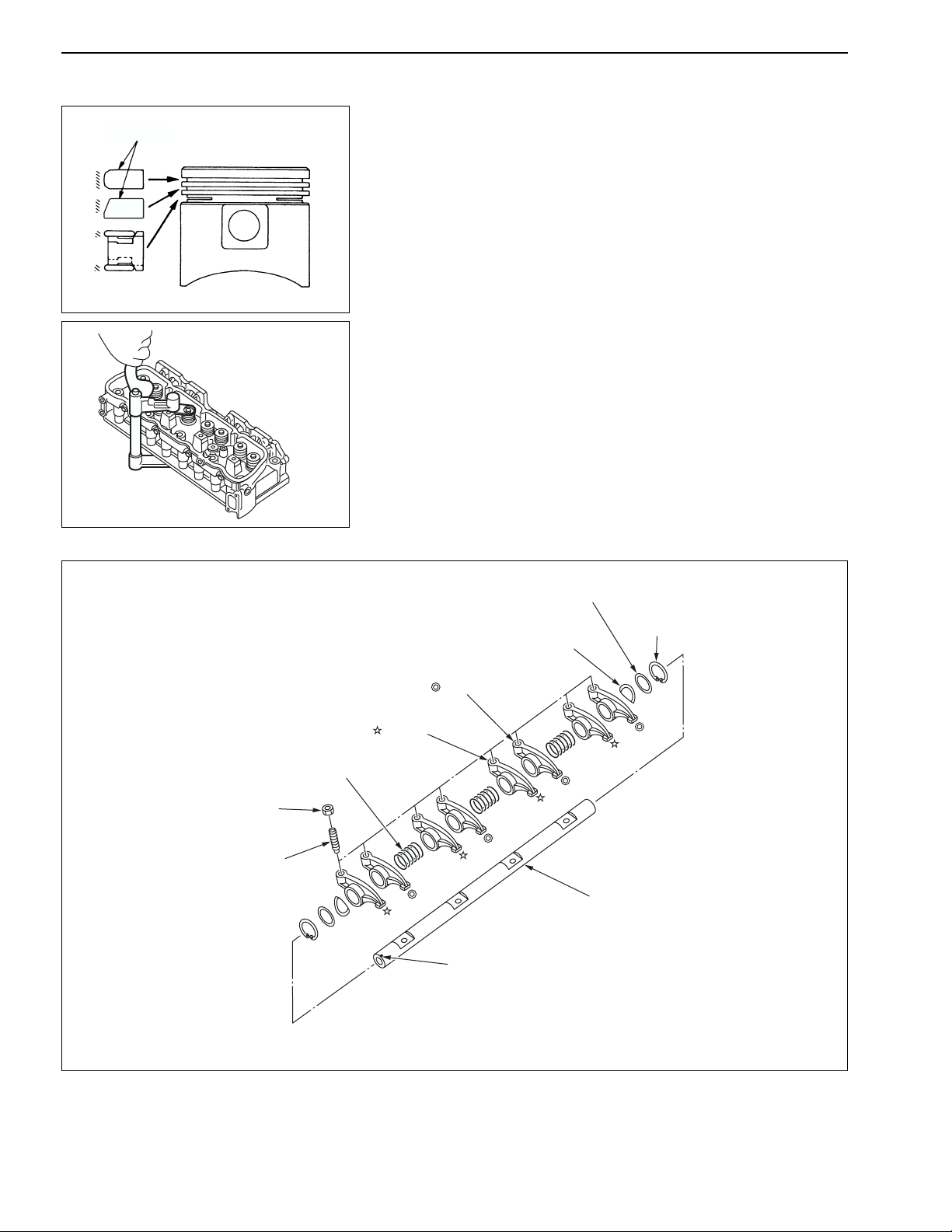
Mark side
ENGINE SERVICE
Engine Assembly (Cont’d)
• The top ring is plated with chrome on its sliding face.
• When installing the compression ring, turn the
manufacturer marking upward.
• The upper and lower combined rings are identical.
EMM0526
EMM0527
4. Assembly of valve and valve spring
• Set the lip seal with the valve oil seal drift (SST) and insert
the valve. Assemble the valve spring and valve spring
retainer in order and insert the collet by compressing the
spring with the valve lifter (SST).
CAUTION:
• Always assemble the valves to their original cylinders.
The wear level of the sliding face differs depending on the
cylinder.
• Face the narrower pitch side of valve spring (with
identification paint mark) toward cylinder head.
• Verify that the valves are seated securely and no foreign
objects are caught inside.
Rocker shaft washer (2)
Snap ring (2)
Valve rocker LH
(4 at
Valve rocker RH
(4 at mark)
mark)
Outside valve
spring (2)
Rocker shaft spring (3)
Adjusting nut (8)
Adjusting screw
Rocker shaft assembly
Mark (Upper, crankshaft pulley side)
EMM0528
5. Rocker shaft assembly
• Apply engine oil to sliding surfaces with rocker shaft of
valve rocker, and assemble it as shown in the figure.
EM-36
Page 96
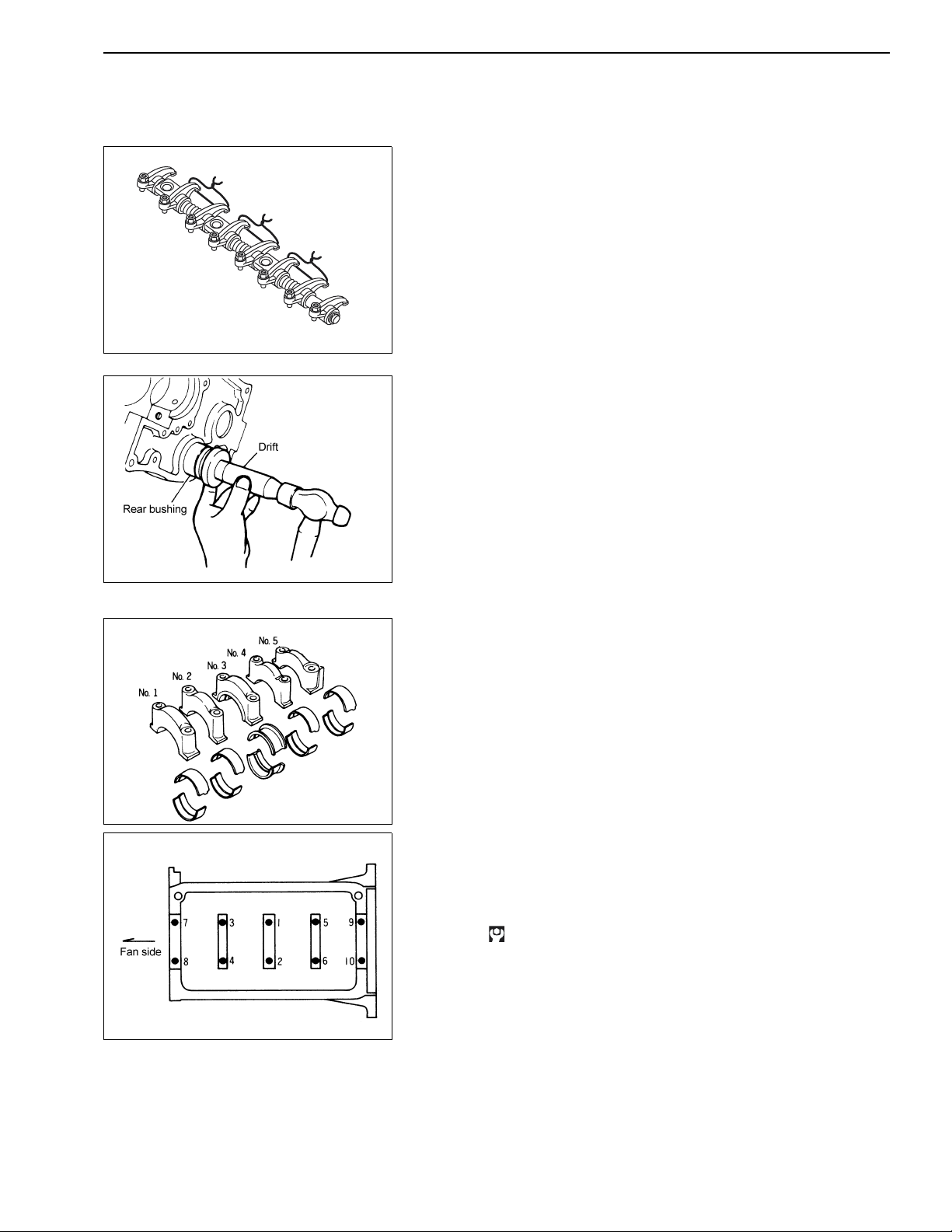
O
EMM0529
ENGINE SERVICE
Engine Assembly (Cont’d)
• There are 2 valve rockers. Be careful about the position
with the paint mark of rocker shaft.
• Compress the coil spring and tie the spring with a metal
wire after assembling. It is easy to assemble to cylinder
head. Wire diameter is 0.5 to 0.8 mm (0.020 to 0.031 in).
6. Assembly of camshaft bushing
• Assembly of rear bushing
Locate the bushing so that the arrow on the bushing faces
upward. Align the bushing to the oil hole on the cylinder
block and drive in the bushing as shown.
• The bushing has a slightly larger diameter toward its rear
end. This ensures that the bushing is press fit into the
cylinder block.
EMM0341
EMM0332
EMM0342
7. Assembly of crankshaft
• Assemble the main bearing bushing to the cap.
• As shown below, the main bearing bushings in use are
classified in two types.
Nos. 1, 2, 4 and 5 are common.
No.3 (center) is provided with a thrust bushing.
• Assemble crankshaft.
• Assemble main bearing caps.
• For the front bearing cap, align the cap to the cylinder block
so that they are flush with each other.
• Apply engine oil to the cap bolts and tighten them to the
specified torque from inside to outside as shown in the
figure on the left.
• Make sure that the crankshaft can be turned with a light
force every time one bolt is tightened.
: 83.4 - 93.2 N•m (8.5 - 9.5 kg-m, 61 - 69 ft-lb)
N
TE:
Cranking torque 15 N•m (1.5 kg-m, 11 ft-lb) or less
CAUTION:
For assembly, see the front of the part. An (embossed) arrow
and numbers indicating the assembly position can be seen.
EM-37
Page 97
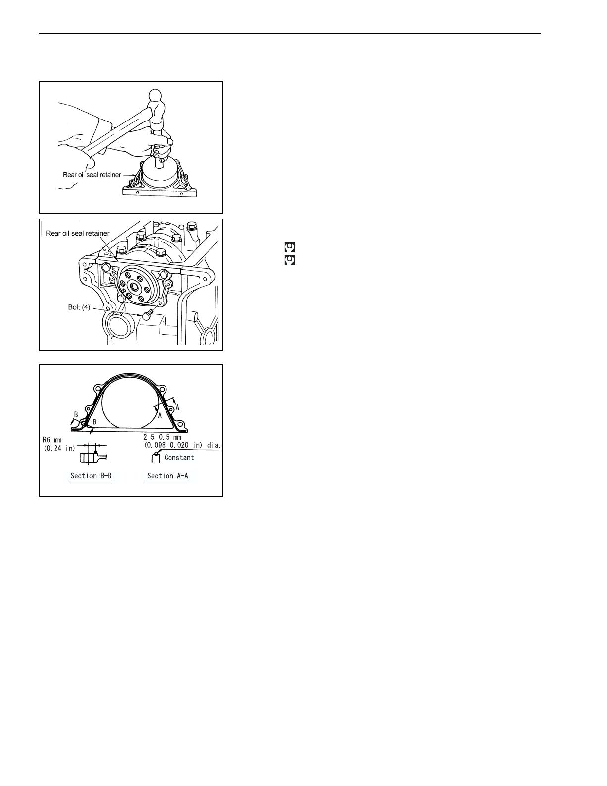
EMM0343
ENGINE SERVICE
Engine Assembly (Cont’d)
8. Assembly of rear oil seal retainer
• Assemble the oil seal to the rear oil seal retainer.
To drive in the oil seal, use the special service tool
(KV10105500).
• Install rear oil seal retainer to cylinder block.
Rear oil seal retainer retaining bolt:
21 - 36 N•m (2.1 - 3.7 kg-m, 15 - 27 ft-lb)
20.6 - 26.5 N•m (2.1 - 2.7 kg-m, 15 - 20 ft-lb)
EMM0345
CAUTION:
• Before installing the rear oil seal retainer, apply liquid
packing to the retainer as shown in the figure.
• Once attaching the retainer and tightening the bolts, do not
make additional tightening or remove the retainer (and
retighten).
• For the mounting face, apply a continuous bead of sealant
±
±
along the groove. For the bolt holes, apply sealant so that it
does not run off the inner edges.
• Make sure to finish the assembly within 5 minutes after
sealant application.
EMM0541
• After the assembly, leave the assembled parts as is for 30
minutes or more.
PRECAUTIONS BEFORE APPLICATION:
• The mounting faces (both sides) shall be free from moisture, oil,
grease, waste, dust and other foreign objects.
• Make sure to remove any sealant from the flange/mounting
faces and threads when reassembling the part that has once
been attached and disassembled.
9. Assembly of piston
(1) Assemble the bearing to the connecting rod.
(2) To each cylinder, assemble the corresponding connecting rod
and piston subassembly according to the cylinder number.
(3) When assembling, turn the front mark of the piston toward the
front.
(4) Set the crankshaft pin positions to TDC or BDC.
EM-38
Page 98
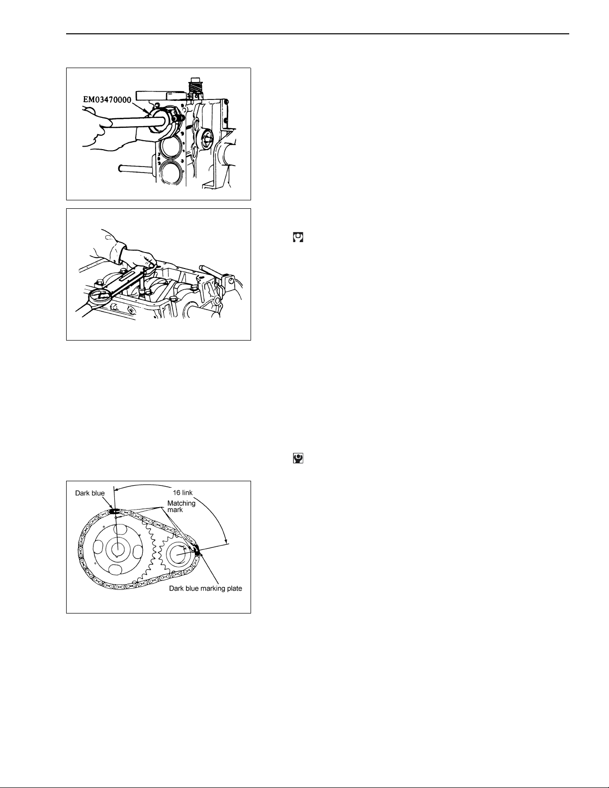
EM164
ENGINE SERVICE
Engine Assembly (Cont’d)
(5) Insert the pistons into the cylinder block using the piston ring
compressor (SST).
CAUTION:
Do not mistake the piston front.
(6) Assemble each connecting rod and connecting rod cap while
aligning their matching marks.
CAUTION:
Install silicon rubber tubes to tip of connecting rod bolt to
prevent crankshaft pin from being damaged.
(7) Tighten connecting rod cap.
Connecting rod cap bolt:
31 - 37 N•m (3.2 - 3.8 kg-m, 23 - 27 ft-lb) (K21, K25)
EM166
EMM0347
10. Assembly of valve lifter
• Fit the valve lifter in the correct position. Apply a small
amount of oil and press the valve lifter into the hole on the
cylinder block.
11. Assembly of camshaft
(1) Gently put the camshaft into the camshaft hole so that the bear-
ing bushings are not damaged.
(2) Tighten locating plate bolt to the specified torque.
M6 x 16 (thread length) 7T bolt:
: 8.43 - 10.8 N·m (0.86 - 1.1 kg-m, 72 -95 in-lb)
12. Assembly of timing chain/sprocket
(1) Tighten camshaft bolts.
Tightening torque: 39.2 - 49.0 N·m (4.0 - 5.0 kg-m, 29 - 36 ft-lb)
(2) Check the height of the camshaft gear and crankshaft gear end
faces, and adjust the height by adding shims to the crankshaft
side as necessary.
(3) Assemble the sprocket and timing chain simultaneously while
aligning their matching marks.
EM-39
Page 99
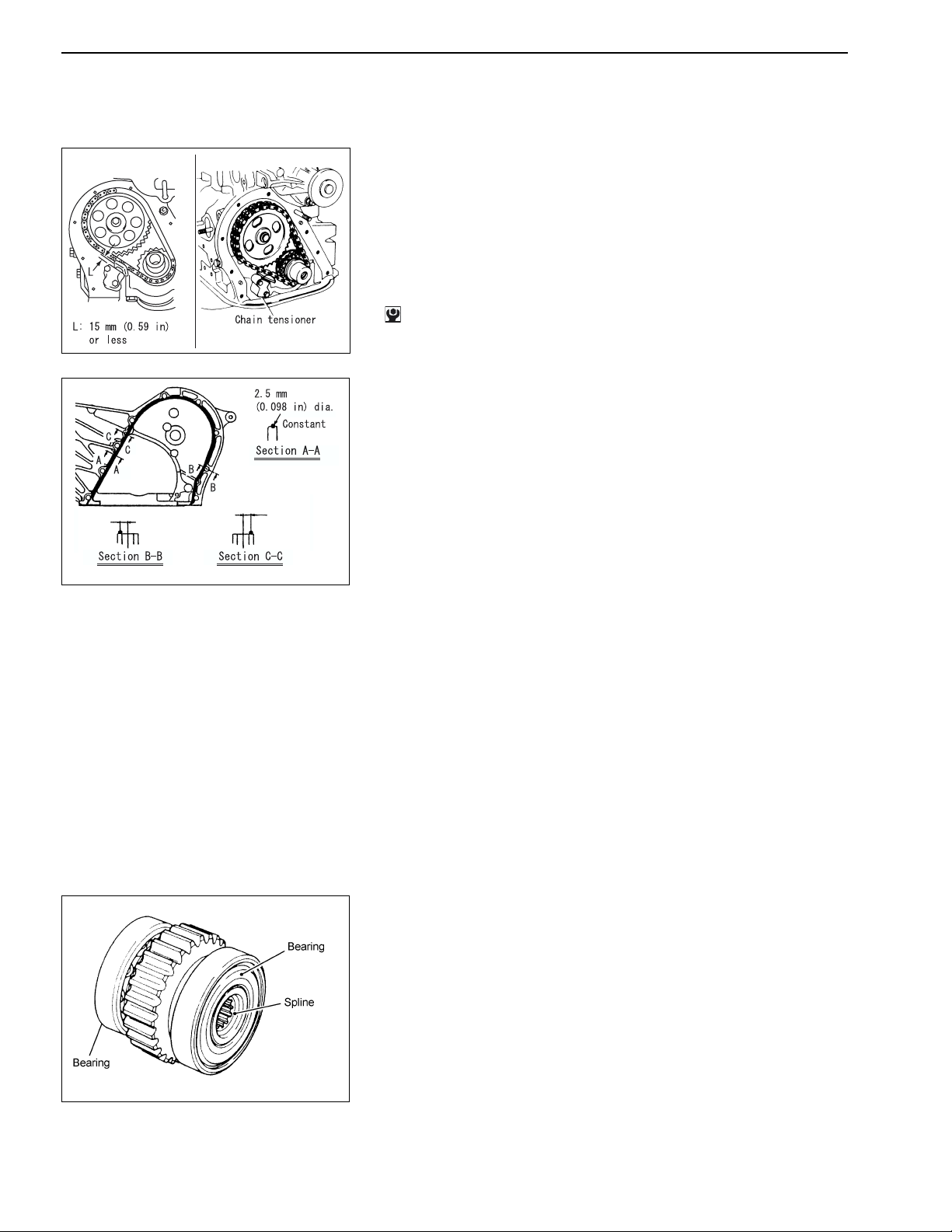
EMM0542
EMM0543
ENGINE SERVICE
Engine Assembly (Cont’d)
13. Installation of timing chain tensioner
• Assemble chain tensioner.
• When installing the chain tensioner, align the oil holes of
the tensioner body to those of the cylinder block to ensure
that the tensioner spindle shoe (synthetic rubber) is held
parallel with the chain.
CAUTION:
Assembling the shoe in the reverse position will prevent
tightening of the tensioner bolt, resulting in tensioner damage.
M6 x 35 (thread length) bolt:
: 8.43 - 10.8 N·m (0.86 - 1.1 kg-m, 75 - 95 in-lb)
14. Installation of timing chain housing
• Before installing the timing chain housing, apply liquid
packing to the housing as shown in the figure.
15. Inspection and installation of oil pump sprocket and chain
PTO DEVICE
Inspection
• Sprocket (Oil pump side)
If the gear teeth have significant scratches, excessive wear
or stepped wear at the spline, replace the sprocket.
• Sprocket (Crankshaft side)
If the gear teeth have significant scratches or wear,
replace the sprocket.
Ball bearing
• If the bearing is loose or drags, replace the sprocket.
• Chain
If the link has significant scratches, stretch (unusual
slapping noise is generated when tilt lever is operated) or
wear, replace the sprocket.
EMM0350
Assembly
• Assemble oil seal to front cover.
Drive in the sprocket using the front oil seal drift
(ST1524S000).
CAUTION:
First, apply grease to the lip of the oil seal. When driving in the
sprocket, ensure that the sprocket is not inclined.
• Install the bearing to the oil pump-side sprocket.
The bearings before and after the sprocket are identical.
To install them, use a press as done for disassembly.
EM-40
Page 100
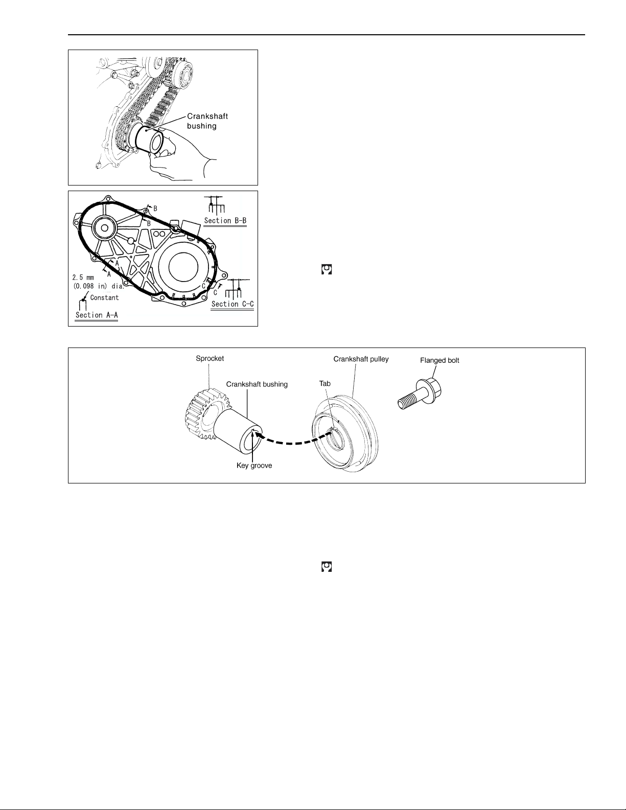
EMM0561
EMM0544
ENGINE SERVICE
Engine Assembly (Cont’d)
• Install the sprocket and chain as an assembly.
Install the chain to the sprocket, and then install the chain
and sprocket assembly to the crankshaft and timing chain
housing.
• Remove any old grease from the oil pump spline and apply
new molybdenum grease.
• Install front cover.
• Install the crankshaft bushing for the crankshaft position
sensor.
Before installing the front cover, apply liquid packing to the
cover as shown in the figure. (Refer to the rear oil seal
retainer installation procedure.)
M8 x 25 (thread length) 7T bolt:
: 20.6 - 26.5 N·m (2.1 - 2.7 kg-m, 15 - 20 ft-lb)
16. Installation of crankshaft pulley
EMM0559
(1) Set the crankshaft pulley by aligning the pulley claws to the
groove of the bushing.
(2) Attach the washer, apply engine oil to the crankshaft pulley bolt
and tighten the bolt.
Crankshaft pulley bolt:
: 220.5 - 240.1 N·m (22.5 - 24.5 kg-m, 163 - 177 ft-lb)
17. Installation of cylinder head
(1) Both ends of cylinder block top
Drive in dowels into the head bolt holes (two positions).
(2) Place the head gasket on the block top with the copper side fac-
ing up.
EM-41
 Loading...