

Page 1
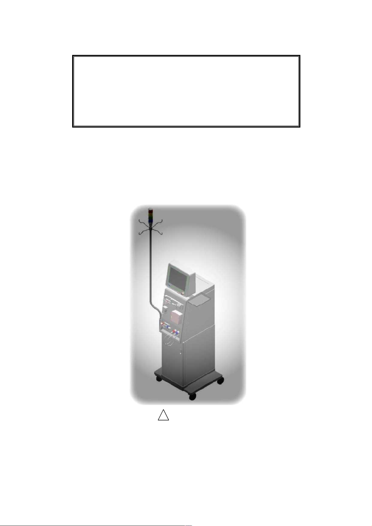
Single patient dialysis machine
SURDIAL 55Plus
Instruction Manual
-- M a i n t e n a n c e M a n u a l - -
!
CAUTION
Read this instruction manual carefully before use.
Improper handling can result in an accident or malfunction.
Use the unit in accordance with this manual.
Keep this manual in a safe place for future reference.
Original Instructions
Page 2

Page 3

Intended Use of This Machine
This machine should be used when physicians prescribe hemodialysis to patients with acute or
chronic renal failure.
Contraindications
This machine is not designed, manufactured, or sold for other use than hemodialysis on patients
with acute or chronic renal failure.
Attention should be paid to contraindications valid for extracorporeal treatment in general.
Safety
Equipment classification and handling precautions
This machine is classified as follows:
1
Type of protection from electric shock······Class I
2
Degree of protection from electric shock······Type B
Ensure to have a protective earth connection with the equipped power plug.
Precaution for fluid penetration
Keep the machine out of water.
Protection against water infiltration······Drip-proof equipment IPX1
Precaution for flammable atmospheres
Do no use this machine in flammable atmospheres..
Preface-1
Page 4

Safety Precautions
Appropriate operation and regular maintenance are essential for safe use of this machine.
Read and understand careful the safety precautions described in this manual before using or servicing
this machine.
The operating procedures and precautions described in this manual are effective only when this
machine is used for its intended purposes. Users shall be liable for all deeds and the safety measures
taken when the machine is used in methods other than specified in this manual.
(1) Degree of damage to health and property, and its indication (Alert symbols and signal words)
The degree of the foreseeable damage to health and property when the machine is misused is
classified into the following three categories, and each category is expressed by the following alert
symbol and signal word.
!
DANGER
This indicates an imminently hazardous situation which, if not avoided, will result
in death or serious injury.
!
WARNING
It indicates a potentially hazardous which, if not avoided, could result in death or
injury.
!
CAUTION
This indicates a potentially hazardous, if not avoided, may result in moderate
injury or damage in property.
(2) Note and its indication
NOTE
Indicates note sentences. Make reference when operating or servicing the
machine.
Due to our constant research and improvement, details of the design of the machine described in
this manual may be slightly different from those of the unit you purchased. If you have any question
about the unit you purchased or contents of this instruction manual, please contact the nearest branch
or agency.
Preface-2
Page 5

Table of Contents
Intended Use of This Machine
Contraindications
Safety
Safety Precautions
1.····Installation Environment············································································1-1
1.1. Installation environment ··································································································1-2
1.2. Workspace required········································································································1-2
1.3. Electric power equipment································································································ 1-3
1.4. Water supply and drainage requirements ·······································································1-3
2.····Precautions for Maintenance·····································································2-1
2.1. Precautions before handling·························································································· 2-2
2.2. Handling the equipment ································································································ 2-2
2.3. Replacement parts ········································································································ 2-2
2.4. Liability for readjustment and repair ··············································································2-2
3.····Daily Inspection ··························································································3-1
3.1 Daily inspection by operator ·························································································· 3-2
3.2 Monthly inspection ········································································································ 3-2
3.3 Maintenance and inspection by Service Technician······················································ 3-2
3.4 Maintenance by Service Technician·············································································· 3-2
3.5 Inspection after a long-term storage·············································································· 3-2
4.····Maintenance and Inspection Instructions ················································4-1
4.1. Maintenance and inspection instructions······································································· 4-2
4.2. Instructions on the maintenance and inspection log······················································ 4-3
5.····Maintenance and Inspection Log ······························································5-1
6.····Maintenance and Inspection Manual ························································6-1
Table of Contents-1
Page 6

7.····Parts Replacement ·····················································································7-1
7.1 List of parts to be maintained and replaced··································································· 7-2
7.2 Parts replacement during maintenance········································································· 7-9
7.3 Miscellaneous part ········································································································ 7-48
7.4 Powder Bicarbonate Assy (option) ················································································ 7-50
7.5 Hot disinfection with citric acid Assy (option)································································· 7-55
8.····Terminology ································································································8-1
9.····Other Adjustments ·····················································································9-1
9.1 Zero compensation of the blood leak detector (BLD-01) ··············································· 9-2
9.2 Adjustment of Overload Sensitivity in Heparin Pump Assembly···································· 9-5
Table of Contents-2
Page 7

1. Installation Environment
1.1. Surrounding environment
1.2. Workspace required
1.3. Electric power equipment ··············································································· 1-3
1.3.1. For the 230V (AC) unit··············································································1-3
1.3.2. For the 110V (AC) unit··············································································1-3
1.4. Water supply and drainage requirements······················································ 1-3
1.4.1. Water supply pressure ··············································································1-3
1.4.2. Water supply flow ······················································································ 1-3
1.4.3. Water supply temperature ········································································· 1-4
1.4.4. Drainage ···································································································· 1-4
················································································ 1-2
························································································ 1-2
1-1
Page 8
The following conditions are required for the installation environment in order to use this
equipment safely and properly.
1.1. Surrounding environment
During operation
Storage and shipping
(with internal fluid)
Storage and shipping
(without internal fluid)
Surrounding temperature
Surrounding humidity (%)
(°C) 15 to 35 5 to 50 -10 to 50
35 to 80
(non condensing)
Air pressure (hPa)
Do not expose this equipment to direct sunlight.
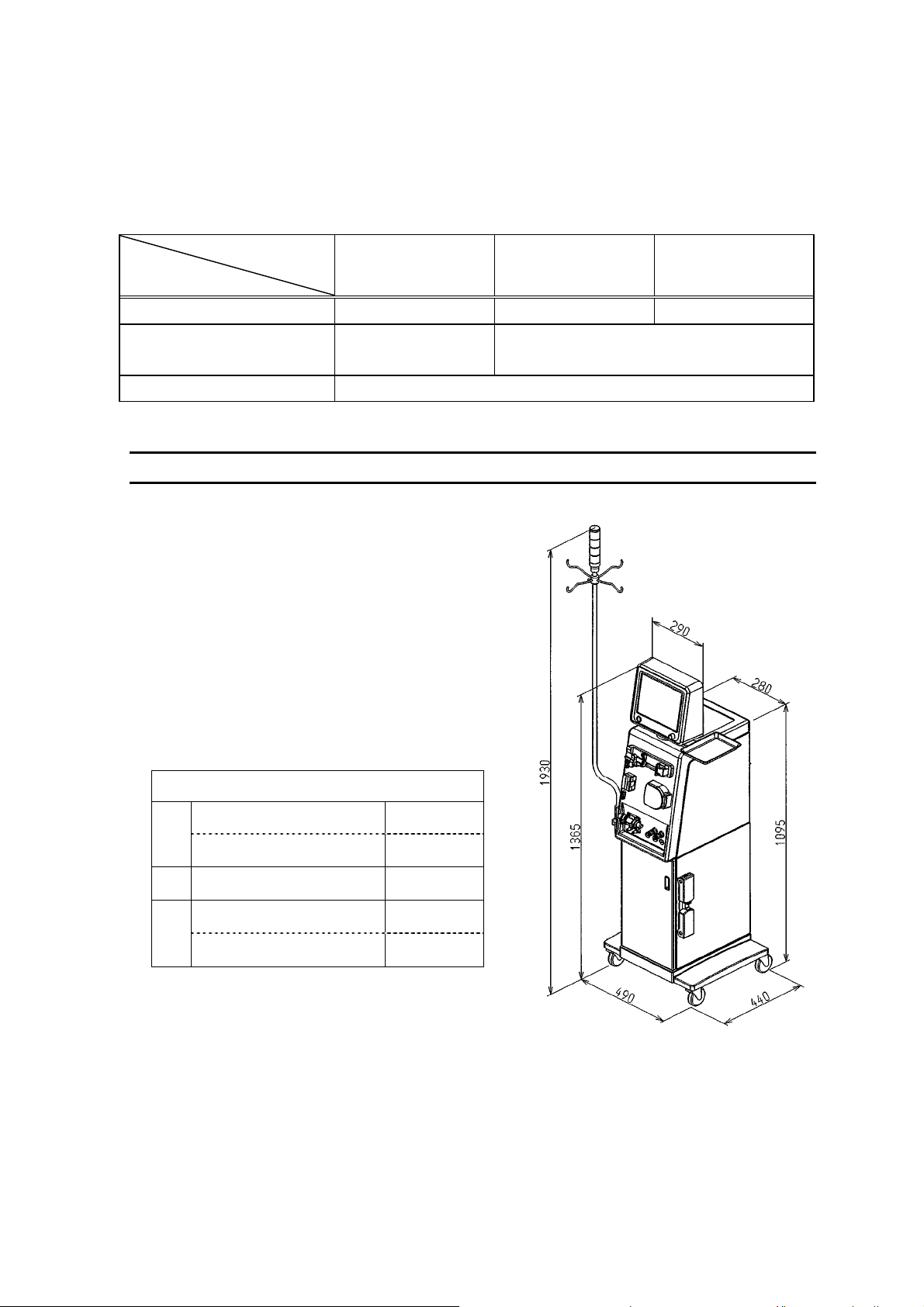
1.2. Workspace required
Prepare a space larger than 5cm, 10cm, and 20cm
above, each side, and back of the equipment,
respectively, with respect to the outside demension.
For ventilation, use a ventilation opening of larger
than φ20cm in diameter or avoid placing an object
next to at least one of the 5 open sides of the
equipment.
Outside demension of the equipment
35 to 85 (non condensing)
795 to 1062
NOTE
1-2
Top
290 mm
W
Wheel part
Wheel part
D
Excluding the infusion stand
490 mm
440 mm
1365 mm
H
Including the infusion stand
1930 mm
Figure 1-1 Outside dimensions of
the equipment
Page 9

1.3. Electric power equipment
1.3.1. For the 230V (AC) unit
The unit requires an 230 V (AC) ±10%, 50/60 Hz power source for proper operation.
A power outlet of 230 V (AC), 10 A or larger with protective earth is required for the standard
machine.
A power outlet of 230 V (AC), 15 A or larger with protective earth is required for the machine
with Hot Citric Option.
Be sure to connect the power plug properly.
1.3.2. For the 110V (AC) unit
The unit requires an 110 V (AC) ±10%, 50/60 Hz power source for proper operation.
A power outlet of 110 V (AC), 15 A or larger with protective earth is required for the standard
machine.
A power outlet of 110 V (AC), 20 A or larger with protective earth is required for the machine
with Hot Citric Option.
Be sure to connect the power plug properly.
!
WARNING
Do not use an AC power plug or adaptor that requires protective earth removal.
Do not use an adaptor for the equipment plug when connecting to the power outlet.
For any problem with the electric power equipment, contact an authorized electrician to check
the wiring.
1.4. Water supply and drainage requirements
Check the following to ensure the proper equipment operation.
1.4.1. Water supply pressure
The normal pressure between 0.05 and 0.74 MPa (0.5 to 7.5 kgf/cm2) is required.
1.4.2. Water supply flow
(1) Standard specification
The water supply flow must be 700 mL/min or higher.
(2) Hot Citric Assy, Variable Dialsate Flow Assy and Mass Flow Assy
The water supply flow must be 900mL/min or higher.
1-3
Page 10
1.4.3. Water supply temperature
(1) Standard specification
A range of 17 to 30°C is necessary.(4 to 30°C with the Heat Exchanger option)
The water supply temperature is minimum 5°C lower than the preset temperature of
dialysate.
(2) Hot disinfection with citric acid Assy, Variable control of dialysate flow Assy and high flow
Assy
A range of 14 to 30°C is necessary. (4 to 30°C with the Heat Exchanger option)
The water supply temperature is minimum 5°C lower than the preset temperature of
dialysate.
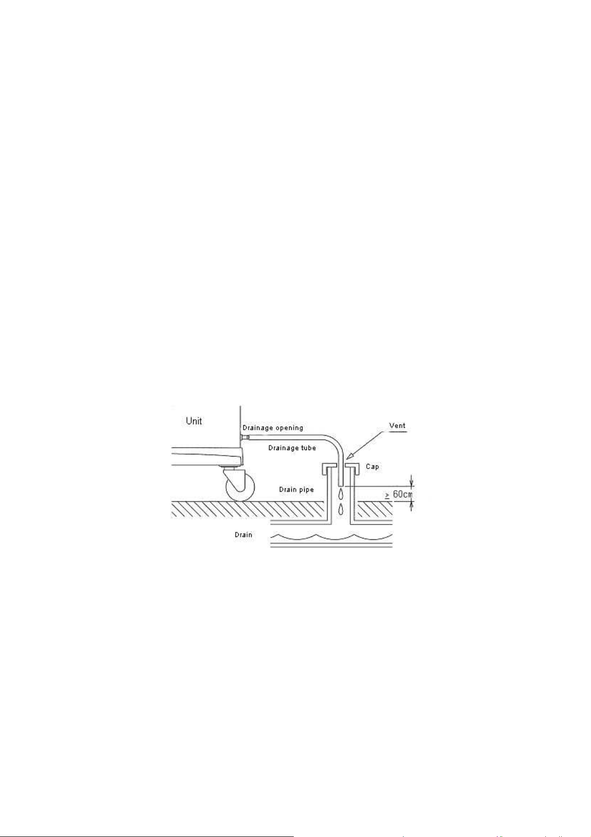
1.4.4. Drainage
Drainage flow must be 1500 mL/min or higher.
Keep the drainage tube 3 m or shorter.
The maximum height of the drain tube is 60 cm, with free outlet to avoid contamination.
1-4
Figure 1-2 Drainage
Page 11

2. Precautions for Maintenance
2.1. Precautions before handling··········································································· 2-2
2.1.1. Service technician····················································································2-2
2.1.2. Well-planned maintenance········································································ 2-2
2.1.3. Clothes ······································································································ 2-2
2.2. Handling the equipment·················································································· 2-2
2.3.
Replacement parts·························································································· 2-2
2.4. Liability for readjustment and repair·······························································2-2
2-1
Page 12

2.1. Precautions to be taken before handling
!
CAUTION
Do not connect the equipment to a patient during maintenance.
2.1.1. Service technician
Only Service technicians who received a technical training of dialysis machines from Nipro, are
allowed to maintain the machine.
Otherwise, a person who is being supervised by a trained technician , is allowed to maintain the
equipment.
2.1.2. Well-planned maintenance
Use of the equipment without planning maintenance, can decrease work efficiency and cause
injury, accident, and errors. It can also interfere with the original purpose, maintenance.
Schedule the time to maintain the equipment, and prepare necessary tools, parts, testing
equipment, and documents in advance.
2.1.3. Clothes
Try to minimize injury and accident by wearing appropriate clothes to work on the equipment.
Select clothes that do not attract a lot of electrostatics. Avoid exposing skin even if the
surrounding temperature is high.
2.2. Handling the equipment
Work in accordance with the instructions.
Read the attached Instruction Manual carefully.
Transport and handle the equipment in accordance with the Manual.
Be sure to check the electric power line, water supply/drainage line, and other connection lines
before working on the equipment.
2.3. Replacement parts
Use the parts specified by the manufacturer.
2.4. Liability for readjustment and repair
A person who readjusted or repaired is liable for consequential events.
2-2
Page 13

3. Daily Inspection
3.1 Daily inspection by operator··········································································· 3-2
3.2 Monthly inspection··························································································· 3-2
3.3 Maintenance and inspection by service technician······································· 3-2
3.4 Maintenance by service technician································································3-2
3.5 Inspection after a long-term storage······························································3-2
3-1
Page 14

!
CAUTION
Do not connect the equipment to a patient during maintenance.
3.1. Daily inspection by operator
Check the following items before and after using the equipment on the same day.
Ensure normal operation of the equipment.
Abnormality, such as leakage around the equipment.
Check loosening of clamps for the water supply opening and drainage opening hoses.
(1) There not being residual chemical solution.
(2) Residual quantities of disinfection or acetic acid solution being enough.
(3) Consumption of disinfection or acetic acid solution being reasonable.
(4) The real concentration of dialysate being reasonable.
(5) There not being abnormal sound, a bad smell, over heat.
(6) The filter of the fan not having blocking.
(7) Foreign substance such as disinfectant stain on the equipment exterior.
(8) Dialysate stain on the equipment. A dialysate stain can cause rust. Wipe it off
immediately.
(9) Abnormality when the start-up test is performed.
(10) If the equipment will be in operation overnight, ensure that the coupler is fit firmly on the
coupler holder.
(11) Confirm that the equipment detects the coupler switch signal.
(12) The syringe must be filled with the preset infusing volume.
3.2. Monthly inspection
Clean the air filter of the fan. (See 7.3.1., 7.3.2.)
3.3. Maintenance and inspection by service technician
Check the working hours. Perform a periodical inspection every 5000 hours or every 6 months.
See “5. Maintenance and Inspection Log” for items to be inspected.
3.4. Maintenance by service technician
Check the working hours. The service technician should maintain the hydrauric line and electrical
board every 5000 hours or every 6 months.
3.5. Inspection after long-term storage
Before starting dialysis treatment after more than 1 month of storage, a disinfection and a water
rinse of minimum 1 hour is required.
Also maintain and inspect the equipment in accordance with “4. Maintenance and Inspection
Instructions.”
3-2
Page 15

4. Maintenance and Inspection Instructions
4.1. Maintenance and inspection instructions······················································· 4-2
4.2. Instructions on the maintenance and inspection log····································· 4-3
4-1
Page 16

!
CAUTION
Do not connect the equipment to a patient during maintenance.
4.1. Maintenance and inspection instructions
The maintenance and inspection log shown in the next chapter is provided to record and keep
the results of maintenance and inspection. The log will help for the future maintenance and
management of the equipment. See “6. Maintenance and Inspection Manual” for the
maintenance and inspection methods. The person who maintains and inspects ( a service
technician or NIPRO personnel ) must record the results in accordance with the instructions
described in 4.2. Make a copy of this form before logging.
4-2
Page 17

4.2. Instructions on the maintenance and inspection log
(1) When to maintain and inspect
Items with the “6” symbol should be inspected every 6 months.
Items with the “6+” symbol should be inspected every 12 months.
(2) Record the model of the equipment.
(3) Record the serial number of the equipment.
(4) Record the duration of the equipment operation.
(5) Record the date when the equipment was installed.
(6) Record the date when the equipment was inspected.
(7) Record the name of the person who inspected.
(8) Enter the results of inspection into the boxes next to the inspection items, using the
following symbols:
Symbol Results of inspection Recording priority
No abnormalities found
X Exchanged 1
A Adjusted 2
T Tightened 3
C Cleaned 4
L Lubricated 5
If two or more maintenance works are performed per item, refer to the above table and use
the symbol with higher priority.
EXAMPLE) When an item is adjusted (A) and cleaned (C), enter “A” into the corresponding
box.
If inspection of an item requires disassembly, draw a circle around the symbol.
(9) Use the “Observation and Notes” column to write information, such as the part exchanged
during maintenance and inspection, when necessary.
Required disassembly for
inspection
NOTE
Execute maintenance and inspection, make sure to keep the maintenance record, and store the
record properly.
!
CAUTION
Dialysate and body fluid can cause infection. Never exchange parts before rinsing the hydraulic
lines.
4-3
Page 18

4-4
Page 19

5. Maintenance and Inspection Log
5-1
Page 20
)
2
)
2
9.Other items to inspect
6.Heparin pump area
6 Dialysate flow rate
(STANDBY, DIALYSIS, RINSING)
(calibration for blood-leak detection)
between displayed and infused volumes
6 Blood leak alarm Stain, leakage, or blockage in filters
alarm
leak
Blood
Observation and Notes
5-2
displayed and actual flow volumes
, or blockage in filters (calibration of the dialysate pressure gauge) 6 Damage/deformation that interfere with functions
leakage
Maintenance and Inspection: 6-month inspection => 6 12-month inspection => 6+
Equipment model: Serial No. of the equipment: Duration of equipment operation:
Date of equipment installation: / / Date of inspection: / / Inspector:
Results of inspection (Inspected: , Disassembled: , Exchanged: X, Adjusted: A, Tightened: T, Cleaned: C, Lubricated: L)
Inspector’s signature:
6 Conditions of connection tubes (bending, etc.) 6 Movement of the heparin pump 6 Bending, leakage, staining, etc of tubes
6 Connection to the drain pipe 6 Loosening of the heparin pump pulley 6 Abnormal sound/smell
6 Presence of damage and connection of cables Consistency
6 Conditions of the grounding conductor 6 Presence of air bubbles in the hydraulic line
6 Damage/deformation that interfere with functions 7.Movements of monitoring and indication alarms 6 Leakage from the hydraulic line
1.Externals, connection tubes, and cables
6 Conditions of the light indicator 6 Temperature-related alarms 6 Filling flow rate (660 to 680 mL/min)
6 Conditions of tubes (bending, etc.) (calibration of concentration indication) 6 Dialysate flow rate
6 Movement of the solenoid valve 6 Venous pressure alarm Tightening the terminal block
6 Movement of the reducing valve (calibration of the venous pressure gauge)
(calibration of temperature indication) 6 Filling complete pressure
2.Water supply, concentrate feeder, and drainage areas 6 Dialysate concentration alarm 0.093 to 0.098 MPa (0.95 to 1.0 kgf/cm
6 Check of the degassing part 6 Arterial pressure alarm 10.Powder Bicarbonate Assy (Option)
6 Movement of the degassing tank (calibration of the arterial pressure gauge) 6 Movement of the solenoid valve
Stain,
6 Conditions of rinse ports 6 Dialysate pressure alarm 6 Bending, leakage, staining, etc of tubes
6 Movement of the solenoid valve 6 Tube error alarm 11.Variable control of dialysate flow Assy and hi Flow Assy (Option)
6 Flow meter display (movement of the air bubble detector) 6 Filling flow rate (880 to 950 mL/min)
6 Movement and leakage in concentrates/UF pumps 6 Insufficient water supply 6 Filling complete pressure
6 Movement during gas purge 6 Alarm buzzer 0.113 to 0.118 MPa (1.15 to 1.2 kgf/cm
3.Closed line area (movement of the blood leak detector)
6 Movement and adjustment during BYPASS
6 Movement of the solenoid valve 6 Short circuit breaker operation
6 Residual disinfectant/acid solution (option) 6 Capacity of the battery for power failure backup
4.Disinfectant/acid solution (option) feeder areas 8.Electric tests
6 Conditions of the tube (bending, etc.) Leakage current
Conditions of the equipment with grounding
between
Consistency
6 Loosening and abnormal sound in the rotating part
5.Blood pump area
Page 21

6. Maintenance and Inspection Manual
6-1
Page 22

3 m
60 cm.
<
Height at the tip of the drain tube:
(2) Length of the drain tube: <
(2) OK if the equipment functions normally
(3) Must not be damaged
(4) Must be connected to a 3P outlet (5) Must not be damaged/deformed
opening and dialyzer coupler must
be closed with a metallic band and
binding band, respectively.
(1) The water supply opening / Drainage
(1) OK if the equipment functions normally
ndicator movements is preset to “1”.
(6) The criteria is applied when the light
conditions
(6) Must light / blinking under the following
Red: lights during the alarm emergence
Yellow: blinking during the standby
process
Green: blinking during the rinse
process
Blue: blinking when timer comp
Exchange the tube with leakage
(1) OK if the equipment functions normally
(2) Must have the movement sound
6-2
Inspection item Inspection method Criteria Note
1. Externals, connection tubes, and cables (1) Conditions of connection tubes.
(1) Visual inspection.
(bending, etc.)
(2) Visual inspection.
(2) Connection to the drain pipe.
(3) Visual inspection.
of cables.
(3) Presence of damage and connection
(4) Visual inspection. (5) Visual inspection.
(4) Conditions of the grounding conductor.
(6) Visual inspection.
with functions.
(5) Damage/deformation that interfere
(6) Conditions of the light indicator.
(1) Visual inspection.
drainage areas
2. Water supply, concentrate feeder, and
(1) Conditions of tubes. (bending, etc.)
(2) Check the movement from MAINTE4.
(2) Movement of the solenoid valve.
Page 23

specified
2
(2) Only a standard specification.
20 mL/min
(4) Adjust using a pinchcock.
(5) Adjust using a pinchcock.
Only a standard specification.
310 mmHg)
(3) Must be 0.037 to 0.041 MPa (280 to
turn on V1, V4, V10 and (V35) from
(3) While water is supplied to the equipment,
MAINTE4. Leave them for approx. 30 sec
and turn OFF V4. Measure the pressure
between the reducing valve and V1.
(4) Must be the PO
(4) Collect the dialysate from the sample port
(5) Water should not exit from the air side
in the standby process.
process.
(5) Visual inspection during the standby
(6) No fluid leakage (7) Must have no stain, leakage, or
(6) Visual inspection during the rinse process. (7) Visual inspection.
blockage
(1) Movement sound must be audible
(1) Operate the equipment manually from
20 mL/min.
between BYPASS and RELE must be
<
coupler line during BYPASS.
(2) Changes in flow must be <
(3) Pumps rotate smoothly
MAINTE4.
process.
(2) Visual inspection during the standby
(3) Perform UF and inspect visually.
(4) Dialysate pressure must be –100 to 0
(4) Short line the FSW connector during the
mmHg
standby process and operate gas purge.
(5) Dialysate must be flowing into the
process.
(5) Visual inspection during the standby
Difference in flow meter displays
Inspection item Inspection method Criteria Note
concentrates/UF pumps.
(3) Movement of the reducing valve.
(4) Check of the degassing part.
(5) Movement of the degassing tank.
(6) Conditions of rinse ports. (7) Stain, leakage, or blockage in filters. 3. Closed line area (1) Movement of the solenoid valve.
(2) Flow meter display.
(3) Movement and leakage in
(4) Movement during gas purge.
BYPASS.
(5) Movement and adjustment during
6-3
Page 24

0.1 ppm.
(2) Use water and measure the flow
volume per min with an electric
balance.
Grease No.: MOLYKOTE
(1) Apply grease on the feed screw part.
BR2 Plus Grease (Dow Corning)
(3) Adjust from MAINTE6 “SYRINGE
RATIO,” if the difference is larger.
10%.
(1) Movement sound must be audible.
MAINTE4.
(1) Operate the equipment manually from
have abnormal sound.
(2) Residual chlorine must be <
min before the water rinse ends in the
(2) Collect a sample from the drain opening 5
(3) OK if the equipment functions normally.
disinfection process.
(3) Visual inspection.
(1) The rotating part should not be loose or
(1) Check the externals and sound.
volume must be 126 to 154 mL/min.
(2) When the display is 140, actual flow
blood line.
(2) Measure the actual flow volume using the
When the display is 330, the actual flow
volume must be 297 to 363 mL/min.
(1) Must move smoothly.
system.
(1) Push the pusher manually to free the
(2) OK if not loose. (3) The difference between the actual and
(2) Tighten the set screw on the pulley. (3) Install a syringe pump with filled with water
preset infusing volumes must be <
and operate at 9.9 mL/hr for 60 min.
6-4
Inspection item Inspection method Criteria Note
areas
4. Disinfectant/acid solution (option) feeder
(1) Movement of the solenoid valve.
(option)
(2) Residual disinfectant/acid solution.
(3) Conditions of the tube. (bending, etc.)
5. Blood pump area (1) Loosening and abnormal sound in the
rotating part.
actual flow volumes.
(2) Consistency between displayed and
6. Heparin pump area
(1) Movement of the heparin pump.
(2) Loosening of the heparin pump pulley. (3) Consistency between displayed and
infused volumes.
Page 25

±0.5 °C.
(1) Difference must be <
2 mEq/L.
out of range.
(2) Difference must be <
(3) Alarm is active when the current level is
out of range.
(4) Alarm is active when the current level is
out of range.
(5) Alarm is active when the current level is
(6)Real Blood leak value must be <150.
(7) Alarm is active.
(8) Alarm is active
(9) OK if buzzer sound is normal. (10) The Real blood leak value is the total
of the specified value of the dummy
simulated filters ±80 ppm.
Turn on the BUBBLE
temperatures in the preparation process.
(1) Compare preset and displayed
(2) Compare displayed and actual
concentration in the preparation
process.
(3) Change the alarm range manually in
Dialysis waiting process.
(4) Change the alarm range manually in
Dialysis waiting process.
(5) Change the alarm range manually in
Dialysis waiting process.
(6) Set the temperature to 36.5 °C in the
preparation process. Read theReal blood
leak value in MAINTE MODE1.
detector.
(7) Remove the tube from the air bubble
DETECTOR switch.
(8) Operate the equipment after decreasing
the water supply to a insufficient level.
the Real blood leak value in MAINTE1.
(9) Check the buzzer sound. (10) Install a simulated blood leak filter. Read
Inspection item Inspection method Criteria Note
(calibration of blood-leak detection)
(calibration of temperature indication)
(1) Temperature-related alarms.
alarms
7. Movements of monitoring and indication
(calibration of concentration indication)
(2) Dialysate concentration alarm.
(calibration of the venous pressure gauge)
(3) Venous pressure alarm.
(calibration of the arterial pressure gauge)
(4) Arterial pressure alarm.
(calibration of the dialysate pressure gauge)
(5) Dialysate pressure alarm.
(movement of the blood leak detector)
(6) Blood leak alarm.
(movement of the air bubble detector)
(7) Tube error alarm.
(8) Insufficient water supply.
(9) Alarm buzzer. (10) Blood leak alarm.
6-5
Page 26

mL/min.
(2) Set the blood pump flow at 150
Set the heparin pump flow at 2.0
mL/h.
Start after charging for 48 hrs.
A new battery allows approx. 30 min
of operation with full charge. The
battery gradually deteriorates
although there is no power failure.
(3) The jig to measure leakage current is
necessary.
The standard of the jig must be in
accordance with JIS-T-1002.
OFF.
(4) The power breaker must be turned
(1) OK if power supply shuts off.
circuit breaker.
(1) Operate the switch to check the short
must operate for >20 min.
(2) The blood pump and heparin pump
and air bubble detector. Turn on the
(2) Attach the blood line on the blood pump
NOTE: It must operate for 20 min,
BLOOD PUMP, HEPARIN PUMP and
considering the time it takes to
complete blood collection in case of
BUBBLE DETECTOR switches. Turn off
the equipment breaker. Mute the buzzer by pressing the
0.5 mA.
The blood pump must stop when the
power failure. This time frame may
vary, depending on the age of the
battery. Exchange the battery if
necessary. Check the following function:
MUTE/RESET switch.
At the same time, check:
sensor detects air bubbles.
· Air bubble detector is on
Remove the blood line from the air bubble
detector.
· Air bubble detector
(3) OK if <
(3) Connect the jig to measure leakage
current to the equipment. Measure the
current in the protective earth conductor
(the grounding conductor of the power
1 Ω.
(4) OK if <
plug) during normal operation.
(4) Use a tester to measure the resistance
between the chamber frame and the
grounding terminal.
6-6
Inspection item Inspection method Criteria Note
backup.
8. Electric tests (1) Short circuit breaker operation.
(2) Battery capacity for power failure
(3) Leakage current.
grounding.
(4) Conditions of the equipment with
Page 27

) when filling is
2
Inspection item Inspection method Criteria Note
tubes. Exchange the tube with leakage.
9. Other items to inspect
(1) Bending, leakage, staining, etc. of (1) Visual inspection. (1) OK if the equipment functions normally.
DIALYSIS, RINSING) present.
(2) Abnormal sound/smell. (STANDBY, (2) Check sounds and smells. (2) OK if no abnormal sounds/smell are
hydraulic line. process.
(3) Presence of air bubbles in the (3) Visual inspection during the standby (3) No air bubbles in the hydraulic line
(4) Leakage from the hydraulic line. (4) Perform the start-up test or the CHECK (4) Test must be completed without a
operation from MAINTE7. problem.
(5) Filling flow rate. (5) In the standby process, measure the (5) Drainage flow rate must be 660 to (5) The system should not complete
drainage flow rate after installing the 680 mL/min. filling within 40 sec.
flow gauge onto the drainage line. Only a standard specification.
(Drainage flow rate: 500 mL/min)
(6) Filling complete pressure. (6) Measure the pressure on the P4- (6) The pressure must be 0.093 to 0.098 (6) Only a standard specification.
discharge side. (FS1-OUT side) Mpa (0.95 to 1.0 kgf/cm
complete.
(7) Dialysate flow rate. (7) Measure the MAX dialysate flow rate. (7) The MAX dialysat flow must be (7) Only a standard specification.
700 mL/min.
(8) Tightening the terminal block. (8) Check the tightening. (8) OK if not loose. (8) The power breaker must be turned
OFF.
6-7
Page 28

) when filling
2
6-8
Inspection item Inspection method Criteria Note
tubes. Exchange the tube with leakage.
10. Powder Bicarbonate Assy (Option)
(1) Movement of the solenoid valve. (1) Check the movement from MAINTE4. (1) Must have the movement sound
(2) Bending, leakage, staining, etc. of (2) Visual inspection. (2) OK if the equipment functions normally.
with functions.
(3) Damage/deformation that interfere (3) Visual inspection. (3) Must not be damaged/deformed
(4) Stain, leakage, or blockage in filters. (4) Visual inspection. (4) Must have no stain, leakage, or
and hi flow Assy (Optional)
blockage
11. Variable control of dialysate flow Assy
(1) Filling flow rate. (1) In the standby process, measure the (1) Drainage flow rate must be 890 to (1) The system should not complete
drainage flow rate after installing the 950 mL/min. filling less than 32 sec.
flow gauge onto the drainage line.
(Drainage flow rate: 500 mL/min)
(2) Filling complete pressure. (2) Measure the pressure on the P4- (2) The pressure must be 0.113 to 0.118
discharge side. (FS1-OUT side) Mpa (1.15 to 1.2 kgf/cm
is complete.
(3) Dialysate flow rate. (3) Measure the MAX level of the dialysate (3) The MAX level must be 800 mL/min.
flow rate.
Page 29

7-1
7. Parts Replacement
7 Parts Replacement ······················································································7-1
7.1 List of parts to be maintained and replaced·················································7-3
7.2 Parts replacement during maintenance·······················································7-8
7.2.1 Water supply filter Assy (F1) ································································7-8
7.2.2 Two-way solenoid valve (V1,V4,V5a,V5b,V6a,V6b,V7a,V7b,V8a
V8b,V9a,V9b,V10,V11,V19,V21)·················7-9
7.2.3 Two-way solenoid valve (V12) ·····························································7-10
7.2.4 Temperature sensor Assy (T) ·······························································7-11
7.2.5 Dialysate pressure sensor Assy (PD)···················································7-12
7.2.6 Conductivity sensor Assy (CD)·····························································7-13
7.2.7 Degassing tank Assy (AS1)··································································7-14
7.2.8 Air elimination tank Assy (AS2) ····························································7-15
7.2.9 Buffer tank Assy····················································································7-17
7.2.10 Magnet gear pump (P1/P2)··································································7-19
7.2.11 Heparin pump Assy (HP)······································································7-23
7.2.12 Blood pump Assy (BP) ·········································································7-26
7.2.13 Sample port Assy (SL)··········································································7-27
7.2.14 Rinse port ·····························································································7-28
7.2.15 Joint of concentrate tank ······································································7-30
7.2.16 Flow sensor Assy (FS1) ·······································································7-32
7.2.17 Flow sensor Assy (FS2/FS4)································································7-33
7.2.18 Coupler Assy ························································································7-34
7.2.19 Blood leak detector Assy (BLD) ···························································7-35
7.2.20 Chamber Assy (Ca/Cb) ········································································7-36
7.2.21 Ultrafiltration pump Assy (UFP)····························································7-37
7.2.22 Pump for A concentrate Assy (P3) ·······················································7-39
7.2.23 Pump for B concentrate Assy (P4) ·······················································7-41
7.2.24 Relief valve Assy (RV)··········································································7-43
7.2.25 Clamp Assy (CLV) ················································································7-44
7.2.26 Other hydraulic components ································································7-46
7.3 Miscellaneous part·······················································································7-47
7.3.1 Air filter··································································································7-47
7.3.2 Air filter 2 ······························································································7-48
7.4 Powder Bicarbonate Assy (option) ······························································7-49
7.4.1 Powder Bicarbonate Cartridge Holder Assy·········································7-49
7.4.2 B powder concentrate air elimination tank Assy (AS3) ························7-51
7.4.3 Pump for B concentrate Assy (P4)·······················································7-52
7.5 Hot disinfection with citric acid Assy (option)···············································7-54
7.5.1 Two-way solenoid valve (V4,V9a,V9b,V11,V19,(V34),(V35))··············7-54
7.5.2 Two-way solenoid valve (V5b,V6a,V6b,V7b,V8a,V8b) ························7-55
7.5.3 Two-way solenoid valve (V5a,V7a)······················································7-56
7.5.4 Two-way solenoid valve (V10) ·····························································7-57
7.5.5 Relief solenoid valve ((V33)) ································································7-58
7.5.6 Conductivity sensor Assy (CD)·····························································7-59
7.5.7 Degassing tank Assy (AS1)··································································7-60
7.5.8 Air elimination tank Assy (AS2) ····························································7-61
7.5.9 Buffer tank Assy····················································································7-63
7.5.10 Magnet gear pump (P1/P2)··································································7-65
7.5.11 Sample port Assy (SL)··········································································7-69
7.5.12 Rinse port ·····························································································7-70
7.5.13 Joint of concentrate tank ······································································7-71
7.5.14 Chamber Assy (Ca/Cb) ········································································7-72
Page 30

7-2
7.5.15 Ultrafiltration pump Assy (UFP)····························································7-74
7.5.16 Pump for A concentrate Assy (P3) ·······················································7-76
7.5.17 Pump for B concentrate Assy (P4) ·······················································7-78
7.5.18 Relief valve Assy (RV)··········································································7-79
7.5.19 Other hydraulic components ································································7-80
7.5.20 Air filter 3 ······························································································7-81
Page 31

7-3
7.1. List of parts to be maintained and replaced
Approximate time to
replace
Code Name of ASSY/Part
Model No. Code No. qty
2 yr Ad libitum
Note
Water supply filter
Assy
93532000 4-030-060 1
1) Filter FI116ATERP265A00 0-201-213 1
F1
2) Packing 01939900124 4-030-066 1
CL filter SSM-3010 0-501-112 1
F2
Coupler line filter SAS-08061 0-501-218 (1)
Option <H>
Two- way s olenoid valve SV2-322-S 2-006-008 2
1) Diaphragm D3A540 0-501-117 2
Best if replace yearly.
V1
V21
2) Valve body D3B1810 0-501-118 2
Two- way s olenoid valve SV2-322-S 2-006-008 1
1) Diaphragm D3A540 0-501-117 1
Best if replace yearly.
2) Valve body D3B1810 0-501-118 1
Two- way s olenoid valve SV2-322-SHW 0-501-126 (1)
Option <H>
1) Diaphragm D3A540 0-501-117 (1)
Best if replace yearly.
V10
2) Valve body D3B1810 0-501-118 (1)
Two- way s olenoid valve SV2-322-S 2-006-008 5 (8)
Option <P><C>
1) Diaphragm D3A540 0-501-117 5 (8)
Best if replace yearly.
2) Valve body D3B1810 0-501-118 5 (8)
Two- way s olenoid valve SV2-422-S 0-501-120 5 (8)
Option <H><P><C>
1) Diaphragm D4A350 0-501-121 5 (8)
Best if replace yearly.
2) Valve body D4B1000 0-501-122 5 (8)
V4
V9a
V9b
V11
V19
(V22)
(V27a)
(V27b)
(V28a)
(V28b)
(V29)
(V30)
(V31)
Two- way s olenoid valve SV2-322-S 2-006-008 6
1) Diaphragm D3A540 0-501-117 6
Best if replace yearly.
2) Valve body D3B1810 0-501-118 6
Two- way s olenoid valve SV2-422-SH 0-501-123 (6)
Option <H>
1) Diaphragm D4A350
0-501-121 (6)
Best if replace yearly.
V5b
V6a
V6b
V7b
V8a
V8b
2) Valve body D4B1021
0-501-124 (6)
Two- way s olenoid valve SV2-322-S 2-006-008 2
1) Diaphragm D3A540 0-501-117 2
Best if replace yearly.
2) Valve body D3B1810 0-501-118 2
Two- way s olenoid valve SV2-422-SHP 0-501-125 (2)
Option <H>
1) Diaphragm D4A350
0-501-121 (2)
Best if replace yearly.
V5a
V7a
2) Valve body D4B1021
0-501-124 (2)
Two- way s olenoid valve SV2-422-S 0-501-120 1 (1)
Option <A>
1) Diaphragm D4A350 0-501-121 1 (1)
Best if replace yearly.
V12
(V17)
2) Valve body D4B1000 0-501-122 1 (1)
Two- way s olenoid valve SV2-322-S 2-006-008 (1)
Option <P>
1) Diaphragm D3A540 0-501-117 (1)
Best if replace yearly.
2) Valve body D3B1810 0-501-118 (1)
Relief solen oid valve
SV2-322S13-SRHW 0-501-127 (1)
Option <H>
1) Diaphragm D3A540 0-501-117 (1)
Best if replace yearly.
(V33)
2) Valve body D3B1810 0-501-118 (1)
*1) Hot disinfection with citric acid Assy : <H>
*2) Powder Bicarbonate Assy : <P>
*3) Acid-Rinsing Port Assy : <A>
*4) CF flashing unit : <C>
Page 32

7-4
Approximate time to
replace
Code Name of ASSY/Part
Model No. Code No. qty
2 yr Ad libitum
Note
Two- way s olenoid valve SV2-422-S 0-501-120 (1)
Option <H>
1) Diaphragm D4A350 0-501-121 (1)
Best if replace yearly.
(V34)
2) Valve body D4B1000 0-501-122 (1)
Two- way s olenoid valve SV2-322-S 2-006-008 (1)
Option <P>
1) Diaphragm D3A540 0-501-117 (1)
Best if replace yearly.
2) Valve body D3B1810 0-501-118 (1)
Two- way s olenoid valve SV2-422-S 0-501-120 (1)
Option <H>
1) Diaphragm D4A350 0-501-121 (1)
Best if replace yearly.
(V35)
2) Valve body D4B1000 0-501-122 (1)
SAS-08019 0-504-170 1
T1
SAS-08020 0-504-171 1
T2
SAS-08021 0-504-172 1
T3
Temperature sensor
Assy TYPE A
SAS-08022 0-504-173 (1)
T7 Option <H>
T1
T2
T3
(T7)
1) Sensor holder 9389 2511 0-504-022 3 (1)
Dialysate pressure
sensor Assy
PD-02 0-504-024 1
1) O-ring S-16 0-504-026 1
Replace when disassembled
PD
2) Manifold 93882911 0-504-025 1
SAS-08027 0-504-156 1
CD1
SAS-08028 0-504-157 1
CD2
Conductivity sensor
Assy
SAS-08029 0-504-158 (1)
CD3 Option <P>
1) O-ring P3 2-002-058 6 (3)
2) Sensor holder 9366 3814 0-504-002 2 (1)
9036V336100 0-504-159 1
T4
9036V337100 0-504-160 1
T5
3) Temperature
sensor
9036V453100 0-504-161 (1)
T6
4) O-ring P4 0-504-006 2 (1)
SAS-08030 0-504-161 1
CD1 Option <H>
SAS-08031 0-504-162 1
CD2 Option <H>
Conductivity sensor
Assy
SAS-08032 0-504-163 (1)
CD3 Option <H><P>
1) O-ring P3 2-002-058 6 (3)
2) Sensor holder 90403814001 0-504-164 2 (1)
9036V336100 0-504-167 1
T4
9036V337100 0-504-168 1
T5
3) Temperature
sensor
9036V453100 0-504-169 (1)
T6
CD1
CD2
(CD3)
T4
T5
(T6)
4) O-ring P4 0-504-006 2 (1)
Degassing tank Assy 93612300 0-501-015 1
1) O-ring G50 9-001-121 1
Replace when disassembled
Degassing tank Assy 90402300 0-501-149 (1)
Option <H>
AS1
1) O-ring G50 9-001-121 (2)
Replace when disassembled
Air eliminati on tank Assy 93532400 0-501-024 1
1) Float OLV-2P-1 (special) 0-201-018 1
Best if replace yearly.
2) O-ring G50 9-001-121 2
3) Packing 01930200088 0-201-016 1
Air eliminati on tank Assy 90402400 0-501-149 (1)
Option <H>
1) Float OLV-5 (special) 0-501-153 (1)
Best if replace yearly.
2) O-ring G50 9-001-121 (2)
AS2
3) Packing 01930200088 0-201-016 (1)
*1) Hot disinfection with citric acid Assy : <H>
*2) Powder Bicarbonate Assy : <P>
Page 33

7-5
Approximate time to
replace
Code Name of ASSY/Part
Model No. Code No. qty
2 yr Ad libitum
Note
B powder c onc entrate
air elimin ation tank As sy
90369700 0-501-154 (1)
Option <P>
(AS3)
1) Packing 90364413001 0-501-156 (1)
Replace when disassembled
BTW Assy 93613500 0-501-037 1
1) O-ring G70 9-001-123 1
Replace when disassembled
BTW Assy 90403500 0-501-164 (1)
Option <H>
BTW
1) O-ring G70 9-001-123 (1)
Replace when disassembled
BTD Assy 93613500 0-501-037 1
1) O-ring
G70
9-001-123 1
Replace when disassembled
BTD Assy 90404500 0-501-165 (1)
Option <H>
BTD
1) O-ring G70 9-001-123 (1)
Replace when disassembled
BTB Assy 90364400 0-501-159 1
BTB
1) Packing 90364413001 0-501-156 1
Replace when disassembled
Magnet gear pump MDG-R2RA24H-57 0-501-010 1
1) Spare kit SK-R2N-34A 0-501-012 1
2) Hose connector 93742611 4-023-030 2
Magnet gear pump MDG-R2RA24H-63A 0-501-128 (1)
Option <H>
1) Spare kit 4A400105 0-501-132 (1)
P1
2) Hose connector 93742611 4-023-030 (2)
Magnet gear pump MDG-R2RA24H-57 0-501-010 1
1) Spare kit SK-R2N-34A 0-501-012 1
2) Hose connector 93742611 4-023-030 2
Magnet gear pump MDG-R2BA24H-65A 0-501-129 (1)
Option <H>
1) Spare kit 4A400105 0-501-132 (1)
P2
2) Hose connector 93742611 4-023-030 (2)
Heparin pump Assy 93896500 0-504-035 1 – –
HP
1) Half nut 91936519 0-504-070 1
Blood pump Assy MRP22-011 0-504-200 1
BP
1) Rotor Assy AS49898-01 0-504-179 1
Sample port Assy 93893400 0-501-067 1
1) Packing (B) 01939800472 0-000-060 1
Sample port Assy 90403400 0-501-179 (1)
Option <H>
SL
1) Packing (B) 01939800472 0-000-060 (1)
QJ-2P-H-2
Red silicone rubber
(sleeve: red)
0-501-091 1
Rinse port
(For concentrate)
QJ-NE2P-H-2
Red silicone rubber
(sleeve: blue)
0-501-092 1
1) O-ring QJR22 9-001-103 2
2) Gasket QJR21 9-001-102 2
SAS-08016 0-501-200
(1)
Option <H>
For A concentrate
Rinse port
(For concentrate)
SAS-08017 0-501-201
(1)
Option <H>
For B concentrate
1) O-ring QJR22 9-001-103 (2)
–
2) Gasket QJR21 9-001-102 (2)
Rinse port
(For disinfectant)
SAS-08018 0-501-095 1
1)Tube connector S 93663311001 0-501-096 1
–
2) Packing (A) 91936944004 2-002-066 1
*1) Hot disinfection with citric acid Assy : <H>
Page 34

7-6
Approximate time to
replace
Code Name of ASSY/Part
Model No. Code No. qty
2 yr Ad libitum
Note
QJ-2PNV-H-2
Red silicone rubber
(sleeve: red)
0-501-082 1
Joint of concentrate
tank (Side of the
dialysate)
QJ-NE2PNV-H blue
Red silicone rubber
(sleeve: blue)
0-501-083 1
1) O-ring QJR22 9-001-103 2
2) Gasket QJR21 9-001-102 2
SAS-08013 0-501-189 (1)
Option <H>
For A concentrate
Joint of concentrate
tank (Side of the
dialysate)
SAS-08014 0-501-190 (1)
Option <H>
For B concentrate
1) O-ring QJR22 9-001-103 (2)
–
2) Gasket QJR21 9-001-102 (2)
Joint of concentrate
tank (Side of the
disinfectant)
SAS-08015 0-501-084 1
–
1) Packing (A) 91936944004 2-002-066 1
Flow sensor Assy
SAS-08004 0-504-181 1
FS1
1) Packing 93614615001 0-504-120 2
Flow sensor Assy
SAS-08005 0-504-184 1
(FS2)
FS4
1) Packing 93614615001 0-504-120 2(2)
Option<H>
SAS-08033 0-501-206 1
Red
Coupler Assy
SAS-08034 0-501-207 1
Blue
–
1) Packing 90363014001 0-501-209 2
Blood leak detector Assy
BLD-01 4-030-078 1
BLD
1) Cartridge holder 93444823100 0-504-034 1
Chamber Assy 90361000 0-501-181 1
1) Diaphragm 0193 0700 083 0-501-184 2
2) Hose connector SYKG-002 0-501-011 4
3) O-ring SSM-07046 0-501-016 4
Chamber Assy 90401000 0-501-186 1
Option<H>
1) Diaphragm 0193 0700 083 0-501-184 2
2) Hose connector SYKG-002 0-501-011 4
Ca
Cb
3) O-ring SSM-07046 0-501-016 4
Ultrafiltration pump
Assy
V-10AUM-P1 0-501-048 1
1) Back sheet 1615001500 0-501-049 1
2) Lip seal 1615003300 0-501-050 3
Ultrafiltration pump
Assy
V-10AUM-P1H 0-501-168 (1)
Option <H>
1) Back sheet 1615001500 0-501-049 (1)
UFP
2) Lip seal 1615003300 0-501-050 (3)
Pump for A
concentrate Assy
V-07AUM-P2A 0-501-051 1
1) Back sheet 1640450500 0-501-052 1
2) Lip seal 1640450400 0-501-053 3
Pump for A
concentrate Assy
V-07AUM-P2AH 0-501-169 (1)
Option <H>
1) Back sheet 1640450500 0-501-052 (1)
P3
2) Lip seal 1640450400 0-501-053 (3)
*1) Hot disinfection with citric acid Assy : <H>
Page 35

7-7
Approximate time to
replace
Code Name of ASSY/Part
Model No. Code No. qty
2 yr Ad libitum
Note
Pump for B
concentrate Assy
V-10AUM-P2B 0-501-057 1
1) Back sheet 1615001500 0-501-049 1
2) Lip seal 1615003300 0-501-050 3
discharge rate
0.60[mL/r]
Pump for B
concentrate Assy
V-10AUM-P3B 0-501-170 (1)
1) Back sheet 1615001500 0-501-049 (1)
2) Lip seal 1615003300 0-501-050 (3)
Option <P>
discharge rate
0.30[mL/r]
Pump for B
concentrate Assy
V-10AUM-P2BH 0-501-171 (1)
1) Back sheet 1615001500 0-501-049 (1)
2) Lip seal 1615003300 0-501-050 (3)
Option <H>
discharge rate
0.60[mL/r]
Pump for B
concentrate Assy
V-10AUM-P3BH 0-501-172 (1)
1) Back sheet 1615001500 0-501-049 (1)
P4
2) Lip seal 1615003300 0-501-050 (3)
Option <H><P>
discharge rate
0.30[mL/r]
Powder Bicarbonate
Cartridge Holder
Assy
90369300 0-507-007 (1)
Option<P>
1)Check valve
90369326001
0-507-020
(1)
2)Nozzle packing
90369324001
0-507-023
(2)
–
3)Packing 90369323001 0-507-024 (2)
Other hydraulic
component
– – – – –
1) L-shaped tube B 01930200077 0-501-221 2(8)
Option<P>
2) L-shaped tube C 93893911001 0-501-222 11(4)
Option<P>
3) Reducer hose
connector
90403911001 0-501-223 1(7)
Option<P>
4) T-shaped
connector S
93663916100 0-501-220 3(3)
Option<P>
5) T-shaped
connector
93613911100 0-501-114 23(4)
Option<P>
6) Hose
connector
01930600070 0-501-116 8(3)
Option<H><P><HE>
7) CL filter SSM-3010 0-501-112 1
8) Filter 93663321100 0-501-217 3 (2)
Option <P><A>
9) Silicone tube ø5×ø11 9-004-038 –
30m of Silicon tube
has been used per
one machine.
If you change whole
tube, you need 30m.
10) Silicone tube ø3 ×ø6 2-002-071 –
6.5m of Silicon tube
has been used per
one machine.
If you change whole
tube, you need 6.5m.
11) Plug 93893020004 0-501-216 (1)
Option <H>
–
12) Concentrate
line filter
SAS-08062 0-501-219 (4)
Option <H><P><A>
Lithium battery CR2032 0-502-220 1
Use something which
has no conductivity
for removal.
–
Ni-cd battery 20KR-CH(3AH) 0-502-085 1
*1) Hot disinfection with citric acid Assy : <H>
*2) Powder Bicarbonate Assy : <P>
*3) Acid-Rinsing Port Assy : <A>
*4) Heat Exchanger Assy : <HE>
NOTE 1) This list doesn’t guarantee the performance of parts within the indicated time frame.
The time to exchange parts, is especially depending on the used concentration of disinfectants.
2) This list shows approximate time when parts have to be replaced except for electric components.
Page 36

7.2 Parts replacement during maintenance
7.2.1 Water supply filter Assy (F1)
7.2.1.1 Overall configuration
6
Assy
7.2.1.2 List of components
No. Name Model No. Code No. Note
1 Cap 93619318 0-201-210
2 Hose connector 93619319 0-201-212
3 Packing 01939900124 4-030-066
4 Filter FI116ATERP265A00 0-201-213
5 Body 93619320 0-201-211
6 Water supply filter Assy 93532000 4-030-060
7.2.1.3 How to replace parts
(1) Disassemble the Water supply filter Assy by turning the cap
(2) Replace the filter
(3) Reassemble by turning the cap
4
and packing
3
.
1
clockwise.
1
counterclockwise.
7-8
Page 37

9
8
6
8
9
8
6
7.2.2. Two-way solenoid valve
(V1,V4,V5a,V5b,V6a,V6b,V7a,V7b,V8a,V8b,V9a,V9b,V10,V11,V19,V21)
7.2.2.1 Overall configuration
11
Assy
7.2.2.2 List of components
No. Name Model No. Code No. Note
1 Actuator Assy – –
2 Core – –
3 Pacless pipe – –
4 Sound damp sheet – –
5 Spring – –
6 Plunger – –
7 Diaphragm support – –
8 Diaphragm D3A540 0-501-117
9 Valve body D3B1810 0-501-118
10 Screw M3×45P2 0-501-119
11 Two-way solenoid Valve SV2-322-S 2-006-008
7.2.2.3 How to replace parts
(1) Unscrew the 2 screws
(2) Remove the diaphragm
(3) Replace the diaphragm
plunger
.)
(4) Reassemble and tighten the screws (
10
. to remove the valve body
from the plunger
and valve body
10
) to the torque of 0.69 N.m (7 kgf.cm).
.
.
. (Enchase the diaphragm
firmly to the
7-9
Page 38

8
8
8
6
2
7.2.3. Two-way solenoid valve (V12)
7.2.3.1 Overall configuration
1
7.2.3.2 List of components
Assy
No. Name Model No. Code No. Note
1 Actuator Assy – –
2 Core – –
3 Pacless pipe – –
4 Sound damp sheet – –
5 Spring – –
6 Plunger – –
7 Diaphragm support – –
8 Diaphragm D4A350 0-501-121
9 Ring – –
10 Valve body D4B1000 0-501-122
11 Screw – –
12 Two-way solenoid Valve
TYPE B
SV2-422-S 0-501-120
7.2.3.3 How to replace parts
(1) Unscrew the 2 screws
(2) Remove the diaphragm
(3) Replace the diaphragm
plunger
.)
11
to remove the valve body
from the plunger 6.
and valve body
(4) Reassemble and tighten the screws
11
to the torque of 0.69 N.m (7 kgf.cm).
10
.
10
. (Enchase the diaphragm
firmly to the
7-10
Page 39

7.2.4 Temperature sensor Assy (T)
7.2.4.1 Overall configuration
Assy
4
7.2.4.2 List of components
No. Name Model No. Code No. Note
1 Sensor holder 93892511 0-504-022
T1 harness 9036V333100 0-504-174
2
T2 harness 9036V334100 0-504-175
T3 harness 9036V335100 0-504-176
T7 harness 9036V426100 0-504-177
3 Hose connector 01930600070 0-501-116 Use arbitrarily.
4 Temperature sensor
Assy
SAS-08019 0-504-170 T1
SAS-08020 0-504-171 T2
SAS-08021 0-504-172 T3
SAS-08022 0-504-173 T7
7.2.4.3 How to replace parts
(1) Pull out the thermistor 2 . (Pull to the right by
referring to the figure on the right.)
(2) The flange part of the thermistor 2 should stop at
the bump located inside of the sensor holder 1.
(See the figure on the right.)
(3) Insert the Hose connector 3 .
Sensor holder
1
Thermistor
2
Bump
7-11
Page 40

7.2.5. Dialysate pressure sensor Assy (PD)
7.2.5.1 Overall configuration
7.2.5.2 List of components
9
Assy
No. Name Model No. Code No. Note
1 Manifold 93882911 0-504-025
2 O-ring S-16 0-504-026
3 Pressure transducer – –
4 Base plate – –
5 Spacer – –
6 Dialysate pressure
sensor board
7 Screw M3×12 0-504-031 With a plain washer and
8 Board cover 93882914 0-504-032
9 Dialysate pressure
sensor Assy
– –
a spring lock washer
PD-02 0-504-024
7.2.5.3 How to replace parts
!
CAUTION
Do not touch the surface of the pressure transducer of the dialysate pressure sensor. It can
cause malfunction.
(1) Remove the board cover 8 .
(2) Unscrew the 2 screws 7 .
(3) Remove the pressure transducer 3 from the manifold 1, using a precision flathead
screwdriver, etc.
(4) Replace the manifold
(5) Reassemble and tighten the screws
1
and O-ring 2.
7
to the torque of 0.69 N.m (7 kgf.cm).
7-12
Page 41

7.2.6 Conductivity sensor Assy (CD)
7.2.6.1 Overall configuration
11
Assy
7.2.6.2 List of components
No. Name Model No. Code No. Note
1 Sensor holder 93663814 0-504-002
2 O-ring P3 2-002-058 Silicone rubber
3 Pin 93153812 2-002-060
4 Screw M3×8 0-201-085 With a plain washer and
a spring lock washer
5 CD1/CD2 harness - -
6 O-ring P4 0-504-006 Silicone rubber
7 Collar 93733820 0-504-007
T4 harness 9036V336100 0-504-159
8
T5 harness 9036V337100 0-504-160
T6 harness 9036V453100 0-504-161
9 Pressor - -
10 Screw M3×8 0-201-085 With a plain washer and
a spring lock washer
5
11 Conductivity sensor
Assy
SAS-08027 0-504-156
SAS-08028 0-504-157
SAS-08029 0-504-158
CD1,
CD2,
CD3,
excluded
5
excluded
5
excluded
7.2.6.3 How to replace parts
(1) Unscrew the 6 screws 4 and 2 screws 10.
(2) Remove the pin 3 and temperature sensor 8 from the sensor holder 1 .
(3) Remove the O-ring 2 from the pin 3 and replace.
(4) Remove the O-ring 6 from the temperature sensor 8 and replace.
(5) Reassemble and tighten the screws 4 to the torque of 0.39 N.m (4 kgf.cm).
O-ring
Chamfering
!
CAUTION
The chamfer side of the collar 7 should be inserted
to direction of the O-ring 6. Inserting into the wrong
side can cause leakage.
7-13
Page 42

7.2.7 Degassing tank Assy (AS1)
7.2.7.1 Overall configuration
×4
7.2.7.2 List of components
9
Assy
×4
×4
No. Name Model No. Code No. Note
1 Case (1) 91933411 0-201-010
2 Wire net 91933015 0-201-013
3 O-ring G50 9-001-121 fluoro rubber
4 Float 93442313 0-201-012
5 Case(2)-L 91933412 0-201-011
6 Screw M4×15 0-201-126 With a plain washer and
7 Plain washer For M4 0-201-132
8 Nut For M4 0-201-127
9 Degassing tank Assy 93612300 0-501-015
7.2.7.3 How to replace parts
(1) Unscrew the 4 screws
(2) Replace the O-ring
(3) Reassemble in the reverse order.
6
.
3
.
7-14
a spring lock washer
Page 43

7.2.8 Air elimination tank Assy (AS2)
7.2.8.1 Overall configuration
18
Assy
7.2.8.2 List of components
No. Name Model No. Code No. Note
1 Case (1) 91933411 0-201-010
2 Wire net 91933015 0-201-013
3 O-ring G50 9-001-121
4 Plate 01939700069 0-201-017
5 Ring – –
6 Float – –
7 Float switch shaft – –
8 Mesh 01930200089 0-501-030
9 Packing 01930200088 0-201-016
10 Case 93312412 0-201-015
11 Nut – –
12 Screw M4×20 0-201-133
13 Nut
14 Tube – –
15 Pin – –
For M4
0-201-127
fluoro rubber
With a plain washer and
a spring lock washer
7-15
Page 44

No. Name Model No. Code No. Note
16 Connector – –
17 Float switch Assy OLV-2P-1 (Special) 0-201-018
18 Air elimination tank Assy 93532400 0-501-024
Consists of
5 , 6 , 7 , 11
7.2.8.3 How to replace parts
(1) Unscrew the 4 screws
(2) Remove the ring 5 and float 6.
(3) Replace the float 6 and 2 O-rings 3. (Bring the float with the insert side up.)
(4) Reassemble in the reverse order.
12
.
7-16
Page 45

7.2.9 Buffer tank Assy
7.2.9.1 Overall configuration
×4
×4
×4
11
BTW Assy
×4
12
BTD Assy
13
BTB Assy
7-17
Page 46

7.2.9.2 List of components
No. Name Model No. Code No. Note
1 Lower tank 91936937 0-201-020
2 O-ring G70 9-001-123 fluoro rubber
3 Upper tank (B) 91936955 0-201-021
4 Screw M4×15 0-201-126
5 Nut For M4 0-201-127
6 Case 90364411001 0-501-160
7 Packing 90364413001 0-501-156
8 BTB lid 90364412001 0-501-162
9 BTB bracket 90364414001 0-501-163
10 Screw
11 BTW Assy 93613500 0-501-037
12 BTD Assy 93613500 0-501-037
13 BTB Assy 90364400 0-501-159
M4×15
0-201-126
With a plain washer and
a spring lock washer
With a plain washer and
a spring lock washer
7.2.9.3 How to replace parts
BTW Assy
11
/ BTD Assy
(1) Unscrew the 4 screws
(2) Replace the O-ring 2 .
(3) Reassemble in the reverse order.
13
BTB Assy
(1) Unscrew the 4 screws
(2) Replace the
Packing
(3) Reassemble in the reverse order.
12
4
.
10
.
7
.
7-18
Page 47

7.2.10 Magnet gear pump (P1/P2)
7.2.10.1 Overall configuration
7.2.10.2 List of components
40
Assy
No. Name Model No. Code No. Note
1 Motor 1430101300 0-501-130
2 Magnet retaining ring MDG0519 0-501-131
5 Rear casing – –
6 Magnet can – –
7 Mounting plate – –
8 Bracket – –
9 Driven gear – –
10 Idler gear – –
11 Gear case – –
12 Straight pin – –
13 Front bearing – –
14 Rear bearing – –
15 Front plate – –
16 Rear plate – –
17 Pump head – –
18 Gasket A – –
7-19
Page 48

No. Name Model No. Code No. Note
8
7
9
2
5
r
19 Gasket B – –
20 Packing B – –
21 Packing C – –
22 Retainer spring – –
23 O-ring – –
32 Small screw – –
35 Small screw – –
36 Small screw – –
37 Hose connector 93742611 4-023-030
38 Spare kit SK-R2N-34A 0-501-012 Consists of
9
10 , 13
,
39 Pump body set MDG-R2RA100-34B 0-201-167 Consists of
2 , 5
to 23,
40 Magnet gear pump MDG-R2RA24H-57 0-501-010
to16,
1
32 , 36
7.2.10.3 How to replace parts
18
.
Driven gea
Forceps
35
to remove the pump part from the motor 1 .
32
to remove the pump head
2
using a forceps, etc. Remove the retainer spring
1
.
!
CAUTION
Remove the magnet retaining ring 2 gently
and slowly. It can deform when excessive force
is applied.
20
, bracket 8,
(1) Unscrew the 3 small screws
(2) Unscrew the 4 small screws
(3) Remove the gasket A
(4) Unscrew the 3 small screws 36. Remove the mounting plate 7, packing B
and gasket B
1
from the pump part.
(5) Remove the rear casing 5 while leaving the packing C 21 on the rear casing 5 . (Liquid
may be present inside the rear casing 5.)
To remove the rear casing 5 , turn the front bearing 13 and rear casing 5 . If the rear
bearing
14
is retained inside the rear casing 5, hold the shaft of the driven gear 9 and
pull it out.
(6) Remove the magnet retaining ring
also.
Hang around the
magnet retaining
ring
Magnet
retaining ring
23
,
2
(7) Remove the magnet can 6 from the driven gear 9. Store the magnet can 6 in a place
where no iron powder, etc. will come in contact.
14
(8) Disassemble in the order of rear bearing
gear case
11
, straight pin
12
, front plate
, rear plate 16, driven gear 9 , idler gear 10,
1
, and front bearing
13
. Handle these parts
carefully. Clean and store them in a place where no dust, etc. will come in contact.
7-20
Page 49

5
23
(9) Attach the O-ring
to the front bearing 13 and rear bearing 14. Apply a thin layer of
silicone grease on the O-ring 23 in advance.
(10) Attach the straight pin
12
to the front bearing 13.
(11) Assemble in the order of front plate
plate
16
, and rear bearing
14
and mount them to (10). Holes of these parts should align.
Be sure to insert the driven gear 9 and the idler gear 10 in the direction shown below:
Driven gear (9)
1
, gear case 11, driven gear 9 , idler gear 10, rear
Front bearing side
Idler gear (10)
Rear bearing side
(12) Insert the magnet can 6 into the driven gear 9 and place the magnet retaining ring 2
using a forceps, etc.
Forceps
!
CAUTION
If the magnet retaining ring 2 is loose, it can
Squeeze in advance.
Magnet
retaining ring
Driven
gear
come out. Enchase while squeezing it.
Enchase the magnet retaining ring 2 firmly
into the gap of the projected driven gear.
(13) Insert the retainer spring
5
firmly. Do not turn the rear casing
22
into the gap of the rear bearing 14, and attach the rear casing
5
when attaching. It should be positioned straight
ahead.
(14) Put the gasket B
19
on the front bearing 13, so that the holes align. Attach the bracket 8
so that the two gaps are aligned.
(15) Install the gasket A
screws
32
to tack.
18
to the front bearing 13 and attach the pump head
17
. Use the 4 small
7-21
Page 50

8
2
Convex
Check the
Check the
direction.
Align the
shapes.
Convex
!
CAUTION
When installing the gasket
18
, check the
direction, so that the holes in the front bearing
13
and gasket
1
match, as shown in the
figure on the left.
Installing in the wrong directory can cause
pump malfunction or water leakage.
Concave
(16) Install the packing B
36
. Tighten with a torque of 0.59 N.m (6 kgf.cm).
(17) Install the pump head
0.78 N.m (8 kgf.cm).
Tighten the small screws
specified torque at the end.
Order of tightening
Concave
Body
20
and mounting plate 7 on the bracket 8 using the 3 small screws
17
using the 4 small screws
32
slowly and diagonally, using equivalent force. Tighten up to the
3
. Tighten the screws to the torque of
!
CAUTION
Pump head
When installing the pump head
17
, do not
tighten with a higher torque than specified or
Small screw
avoid tightening only one side. It can damage
the screw part of the front bearing
13
.
(18) Install the reassembled pump part to the motor 1 using the 3 small screws
35
.
7-22
Page 51

7-23
7.2.11 Heparin pump Assy (HP)
7.2.11.1 Overall configuration
7.2.11.2 List of components
No.
Name Model No. Code No Note
1 Pusher E 93896511 0-504-036
2 Button 93896538 0-504-037
3 Coil spring No.1043 0-504-038
4 Pin 93896537 0-504-039
5 Screw M3×8 0-201-091
With a plain washer and
a spring rock washer
6 Metal fitting 93896533 0-504-041
7 Harness holder B 93886530 0-504-042
8 Screw M3×8 0-201-091
With a plain washer and
a spring rock washer
9 Sensor blacket 93886536 0-504-044
10 Limit switch SS-01 0-504-045
11 Screw M2.3×12 0-201-096
With a plain washer and
a spring rock washer
12 Screw M3×8 0-201-091
With a plain washer and
a spring rock washer
13 Syringe holder 93886513 0-504-048
14 Shaft A 93896524 0-504-049
15 Screw M4×8 0-504-050
50
Assy
Page 52

7-24
No.
Name Model No. Code No Note
16 Coil spring No.1145 0-504-051
17 Stopper 93886535 0-504-052
18 Screw M3×8 0-201-091
With a plain washer and
a spring rock washer
19 Syringe base 93896532 0-504-054
20 Packing 93146537 0-504-055
21 Screw M4×16 0-504-056
With a spring rock
washer
22 Chassis 93886514 0-504-057
23 Motor plate 93886515 0-504-058
24 Screw M4×8 0-201-071
With a plain washer and
a spring rock washer
25 Stepping motor KT42JM4-004 4-028-013
26 Screw M3×8 0-201-091
With a plain washer and
a spring rock washer
27 Timing pulley 10XL037 0-504-062
28 Timing pulley 12XL037 0-504-063
29 Timing belt 70-XL-025U 0-204-043
30 Setscrew M4×4 0-504-065
31 Screw M3×8 0-504-066
32 Plate 93886520 0-504-067
33 Plate 2 93886529 0-504-068
34 Shaft 93896519 0-504-069
35 Half nut 91936519 0-504-070
36 Clutch spring 91936523 0-504-071
37 Spring case 93146521 0-504-072
38 Screw M3×10 0-504-073
With a plain washer and
a spring rock washer
39 Rotation detection
sensor
– –
40 Dog 93896534 0-504-075
41 Bearing RF-1450ZZ 0-504-076
42 Feed screw 93896517 0-504-077
43 Housing 93896516 0-504-078
44 Guide shaft 93896518 0-504-079
45 Limit switch SS-01 0-504-045
46 Screw M2.3×12 0-201-096
With a plain washer and
a spring rock washer
47 Nut 93886523 0-504-082
48
Lever 91936927 0-504-083
49
O.L spring 01930600121 0-504-084
50
Heparin pump Assy 93896500 0-504-035
Page 53

7-25
7.2.11.3 How to replace parts
(1) Loosen the setscrews
30
(4 in total). Remove the pulley
28
from the feed screw
42
and the
pulley
27
from the stepping motor
25
.
(2) Unscrew the 4 screws
24
and disassemble into chassis
22
, motor plate
23
, and housing
43
.
(3) Push the shaft
34
in the housing
43
part to remove the feed screw
42
.
(4) Unscrew the 4 screws
31
.
(5) Open a space between the lever
48
(resin part) and the metal part of the housing
43
part by
inserting a flathead screw driver, etc. Insert a screwdriver, etc. while pressing and squeezing the
spring inside the housing by hand.
(6) Rotate the shaft
34
by 90 degrees, and replace the half nut
35
.
(7) Reassemble in the reverse order.
Page 54

7-26
7.2.12 Blood pump Assy (BP)
7.2.12.1 Overall configuration
7.2.12.2 List of components
No.
Name Model No. Code No. Note
1 Housing Assy AR02672-01 0-504-178
2 Rotor Assy AS49898-01 0-504-179 Rotational handle built-in
3 Screw M5×10 0-504-180
With a plain washer and
a spring rock washer
4 BP cover Assy SAS-08035 0-504-190
With pin
5 Motor FY6PF6G-303 0-504-191
6 Blood pump Assy MRP22-011 0-504-200
7.2.12.3 How to replace parts
[How to replace Rotor Assy]
(1)
Pull open the handle of the Rotor Assy
2
.
(2) Remove the Hex socket head cap screw with captive washer
3
.
(3) Pull out the Rotor Assy
2
.
(4) Reverse above procedure when mounting parts.
[How to replace BP cover Assy]
(1)
Remove carefully the pin
4
to upper side (the knurling side of the pin) of the BP cover Assy.
(2)
Insert the pin
4
(the knurling side is upper) when mounting the BP cover Assy.
!
CAUTION
Replace maximum 3 times the BP cover Assy to prevent a decline of fixed power of the pin.
Remove the pin very carefully because holes of the Housing are sometimes transformed
when the pin is removed by force.
6
Assy
Page 55

7.2.13 Sample port Assy (SL)
7.2.13.1 Overall configuration
6
7.2.13.2 List of components
Assy
No. Name Model No. Code No. Note
1 Body 01930400069 0-201-044
2 Spring 919388670041 2-002-063
3 Valve 90403411001 0-201-043
4 Packing (B) 01939800472 0-000-060
5 Syringe holder 01930400085 0-201-042
6 Sample port Assy 93893400 0-501-067
7-27
Page 56

7.2.14 Rinse port
7.2.14.1 For concentrate
7.2.14.1.1Overall configuration
9
Socket
7.2.14.1.2 List of components
. Name Model No. Code No. Note
1 Body - -
2 O-ring QJR22 9-001-103 Silicone rubber (red)
3 Washer - -
4 Gasket QJR21 9-001-102 Silicone rubber (red)
5 Valve QJT24 0-201-137
6 Valve ring QJS23 0-201-138
7 Adapter body - -
8 Adapter nut - -
QJ-2P-H-2
Red silicone rubber
(sleeve: red)
QJ-NE2P-H Blue
Red silicone rubber
(sleeve: blue)
P-13P (Red) 0-501-198 For A concentrate 10 Plug
P-NE13P 0-501-199 For B concentrate
0-501-091 For A concentrate 9 Socket
0-501-092 For B concentrate
Note) Be aware of the direction of the notch during the parts replacement of
4
Be aware of the direction of the parts replacement
3
side
.)
. (The flat side of 4 must be the washer
3
.
7-28
Page 57

7.2.14.2For disinfectant
7.2.14.2.1 Overall configuration
6
Rinse port (For disinfectant)
7.2.14.2.2 List of components
No. Name Model No. Code No. Note
1 Tube connector S 93663311001 0-501-096
2 Connecter holder 91936940004 2-002-068
3 Packing(A) 91936944004 2-002-066
4 Holder base 91936941004 2-002-067
5 Silicone tube ø5×ø11×L500 9-004-038
6 Rinse port
(For disinfectant)
SAS-08018 0-501-095
7-29
Page 58

7.2.15 Joint of concentrate tank
7.2.15.1 Side of the dialysate
7.2.15.1.1 Overall configuration
10
Joint of concentrate tank
(Side of the dialysate)
7.2.15.1.2 List of components
9
Soket
No. Name Model No. Code No. Note
1 Body - -
2 O-ring QJR22 9-001-103
3 Washer - -
4 Gasket QJR21 9-001-102
5 Adapter body - -
6 Nut - -
7 Silicone tube ø5×ø11×L35 0-501-089
8 JUNFLON FEP tube TF185 0-201-048
QJ-2PNV-H-2
red silicone rubber
QJ-NE2PNV-H blue
red silicone rubber
SAS-08007 0-501-078 For A concentrate 10 Joint of concentrate tank
(Side of the dialysate)
SAS-08008 0-501-079 For B concentrate
0-501-082 For A concentrate 9 Socket
0-501-083 For B concentrate
3
Note) Be aware of the direction of the notch during the parts replacement of
.
Be aware of the direction of the parts replacement 4. (The flat side of 4 must be the washer
3
side
.)
7-30
Page 59

7.2.15.2 Side of the disinfectant
7.2.15.2.1 Overall configuration
7
Joint of concentrate tank
(Side of the disinfectant)
7.2.15.2.2 List of components
No. Name Model No. Code No. Note
1 Connecter holder 91936940004 2-002-068
2 Packing(A) 91936944004 2-002-066
3 Holder base 91936941004 2-002-067
4 Nut 91933311010 0-000-075
5 Silicone tube ø5×ø11×L35 0-501-089
6 JUNFLON FEP tube TF185 0-201-048
7 Joint of concentrate tank
(Side of the disinfectant)
SAS-08015 0-501-084
7-31
Page 60

7.2.16. Flow sensor Assy (FS1)
7.2.16.1Overall configuration
11
7.2.16.2 List of components
Assy
No. Name Model No. Code No. Note
1 Block 01930500018 0-504-134
2 Packing 93614615001 0-504-120
3 Pipe 93614617001 0-504-182
4 Screw M3×16 0-201-090 With a plain washer and
a spring lock washer
5 Photo sensor EE-SPX303 0-504-127
6 Hexagon bolt M4×8 0-504-130
7 Nut For M4 0-201-127
8 Screw M4×10 0-201-128 With a plain washer and
a spring lock washer
9 Bracket 90404611101 0-504-183
10 Teflon ball Spare 1/4 (precision 50µ) 0-504-122
11 Flow sensor Assy SAS-08004 0-504-181
7-32
Page 61

7.2.17. Flow sensor Assy (FS2/FS4)
7.2.17.1Overall configuration
12
Assy
7.2.17.2 List of components
No. Name Model No. Code No. Note
1 Block 01930500018 0-504-134
2 Packing 93614615001 0-504-120
3 Pipe SSM-08030 0-504-185
4 Screw M3×16 0-201-090 With a plain washer and
a spring lock washer
5 Photo sensor EE-SPX303 0-504-127
6 Hexagon bolt M4×8 0-504-130
7 Nut For M4 0-201-127
8 Screw M4×10 0-201-128 With a plain washer and
a spring lock washer
9 FS bracket 90404612101 0-504-186
10 Teflon ball Spare 1/4 (precision 50µ) 0-504-122
11 Nut For M4 0-201-127
12 Flow sensor Assy SAS-08005 0-504-184
7-33
Page 62

7.2.18 Coupler Assy
7.2.18.1 Overall configuration
7.2.18.2 List of components
7
Assy
No. Name Model No. Code No. Note
1 Socket 90363011001 0-501-208
2 Packing 90363014001 0-501-209
Slider R 90363013001 0-501-210 Red 3
Slider B 90363012001 0-501-211 Blue
4 Spring 91933314001 0-501-212
5 Steel ball MDM-3006 0-501-213
6 Stop ring 91933312001 0-501-214
SAS-08033 0-501-206 Red 7 Coupler Assy
SAS-08034 0-501-207 Blue
7-34
Page 63

7.2.19 Blood leak detector Assy (BLD)
7.2.19.1 Overall configuration
1
7.2.19.2 List of components
2
4
Assy
3
No. Name Model No. Code No. Note
1 Body – –
2 Cartridge 93444823100 0-504-034
3 Screw – –
4 Blood leak detector
Assy
BLD-01 4-030-078
With a plain washer and
a spring lock washer
7-35
Page 64

7.2.20 Chamber Assy (Ca/Cb)
7.2.20.2 Overall configuration
7.2.20.2 List of components
11
Assy
No. Name Model No. Code No. Note
1 Two-way solenoid valve SV2-322-S 2-006-008
2 Chamber flame 01930700276 0-501-182
3 Hose connector SYKG-002 0-501-011
4 O-ring SSM-07046 0-501-016 Silicone rubber
5 Valve bracket A 9388 2712 0-501-077
6 Tap plate SYKG-003 0-501-183
7 Casing R SYKG-001R 0-501-017
8 Casing L SYKG-001L 0-501-018
9 Diaphragm 0193 0700 083 0-501-184
10 Liquid chamber SAS-08006 0-501-185 Consists of
3 ,4 ,6
11 Chamber Assy 90361000 0-501-181
to 9
7-36
Page 65

7.2.21 Ultrafiltration pump Assy (UFP)
7.2.21.1 Overall configuration
7.2.21.2 List of components
10
Assy
No. Name Model No. Code No. Note
1 3-phase Stepping motor – –
2 Drive joint – –
3 Back sheet 1615001500 0-501-049 For φ10
4 Lip seal 1615003300 0-501-050 For φ10
5 Hexagon cap nut – 0-501-224
6 Pump head Assy – –
7 Fixed screw – –
8 Fixed plate – –
9 Set screw – –
10 Ultrafiltration pump Assy
(Piston pump)
V-10AUM-P1 0-501-048
3 ,4 ,5
included
7-37
Page 66

7.2.21.3 How to replace Lip Seal and Back Sheet
(1) Unscrew the set screw
(2) Unscrew the fixed screw
(3) Remove the body of the pump head Assy
(4) Remove the hexagon cap nut
(5) Reassemble in the opposite procedure. Hold the lip seals
9
.
7
and remove the fixed plate
5
and replace the back sheet
6
from the drive joint
8
.
2
.
3
and lip seal 4 .
4
in the direction as the
diagram below indicates, and insert them carefully into back of the plunger one by one
turning around slightly.
4
Note. 1) Do not bend or damage the lip seals
2) After attaching the lip seals
4
, wipe the plunger off with alcohol, etc. so that
.
any adhesion of finger trace or dust does not remain.
(6) When fixing the pump head Assy
9
so that angle of A measurement in the figure becomes approximately 20°.
(7) After the reassemble, the discharge rate of the pump should be confirmed to be
6
, in the case of Ultrafiltration pump, fasten set screw
7.5 mL/10 rev±3 % in the case of Ultrafiltration pump.
6
(8) If the discharge rate is out of the rage, adjust the angle of the pump head Assy
of
(6).
Plunger
Back sheet
Lip seals
Fitting
Hexagon cap nut
7-38
Page 67

7.2.22 Pump for A concentrate Assy (P3)
7.2.22.1 Overall configuration
11
7.2.22.2 List of components
(Right-side projected×2)
(Left-side projected×1)
Details of section B
Assy
No. Name Model No. Code No. Note
1 3-phase Stepping motor – –
2 Drive joint – –
3 Back sheet 1640450500 0-501-052 For φ7
4 Lip seal 1640450400 0-501-053 For φ7
5 Adapter – 0-501-226
6 Hexagon cap nut – 0-501-224
7 Pump head Assy – –
8 Fixed screw – –
9 Fixed plate – –
10 Set screw – –
11 Pump for A concentrate
Assy (Piston pump)
V-07AUM-P2A 0-501-051
3 ,4 ,5 ,6
included
7-39
Page 68

7.2.22.3 How to replace Lip Seal and Back Sheet
(1) Unscrew the set screw
(2) Unscrew the fixed screw
(3) Remove the body of the pump head Assy
(4) Remove the hexagon cap nut
4
and lip seal
(5) Reassemble in the opposite procedure. Hold the lip seals
.
10
.
8
and remove the fixed plate
6
and the adapter 5, and replace the back sheet
7
from the drive joint
9
.
2
.
4
in the direction as the
3
diagram below indicates, and insert them carefully into the back of the plunger one by
one turning around slightly.
4
Note. 1) Do not bend or damage the lip seals
.
2) After attaching the lip seals 4, wipe the plunger off with alcohol, etc. so that
any adhesion of finger trace or dust does not remain.
(6) When fixing the pump head Assy
10
screw
(7) After the reassemble, the discharge rate of the pump should be confirmed to be 1.3 mL/
so that angle of A measurement in the figure becomes approximately 7°.
7
, in the case of pump for A concentrate, fasten set
10 rev±7 % in the case of pump for A concentrate.
7
(8) If the discharge rate is out of the rage, adjust the angle of the pump head Assy
of
(6).
Plunger
Back sheet
Lip seals
Fitting
Hexagon cap nut
7-40
Page 69

7.2.23 Pump for B concentrate Assy (P4)
7.2.23.1 Overall configuration
7.2.23.2 List of components
10
Assy
No. Name Model No. Code No. Note
1 3-phase stepping motor – –
2 Drive joint – –
3 Back sheet 1615001500 0-501-049 For φ10
4 Lip seal 1615003300 0-501-050 For φ10
5 Hexagon cap nut – 0-501-224
6 Pump head Assy – –
7 Fixed screw – –
8 Fixed plate – –
9 Set screw – –
10 Pump for B concentrate
Assy (Piston pump)
V-10AUM-P2B 0-501-057 0.60mL/r
3 ,4 ,5
included
7-41
Page 70

7.2.23.3 How to replace Lip Seal and Back Sheet
(1) Unscrew the set screw
(2) Unscrew the fixed screw
(3) Remove the body of the pump head
(4) Remove the hexagon cap nut
(5) Reassemble in the opposite procedure. Hold the lip seals
9
.
7
and remove the fixed plate
Assy
5
and replace the back sheet 3 and lip seal 4 .
6
from the drive joint
8
.
2
.
4
in the direction as the
diagram below indicates, and insert them carefully into back of the plunger one by one
turning around slightly.
4
Note. 1) Do not bend or damage the lip seals
4
2) After attaching the lip seals
, wipe the plunger off with alcohol, etc. so that
.
any adhesion of finger trace or dust does not remain.
(6) When fixing the pump head Assy
9
screw
(7) After the reassemble, the discharge rate of the pump should be confirmed to be 6.0 mL/
so that angle of A measurement in the figure becomes approximately 16°.
6
, in the case of pump for B concentrate, fasten set
10 rev±7 % in the case of pump for B concentrate.
6
(8) If the discharge rate is out of the rage, adjust the angle of the pump head Assy
of
(6).
Plunger
Back sheet
Lip seals
Fitting
Hexagon cap nut
7-42
Page 71

7.2.24 Relief valve Assy (RV)
7.2.24.1 Overall configuration
7
Assy
7.2.24.2 List of components
No. Name Model No. Code No. Note
1 Valve body ACB060 0-501-173
2 Seat holder ACY040 0-501-174
3 Spring ACK420 0-501-175
4
Lock nut – –
5
O-ring P9DC 0-201-222
6
Sub body – –
7
Relief valve Assy AC-2200-53B 4-042-011
7-43
Page 72

7.2.25 Clamp Assy (CLV)
7.2.25.1 Overall configuration
7.2.25.2 List of components
23
Assy
No. Name Model No. Code No. Note
1 Solenoid 7SC AWG.25X3X4 long life 0-504-094
2 Solenoid BKT 9389 6211 0-504-095
3 Cooling plate 9389 6214 0-504-096
4 Screw M3×4 0-201-175
5 Nut For M6 0-504-098 With spring rock /
6 Spring BKT 9389 6213 0-504-099
7 Sensor BKT 9389 6218 0-504-100
8 Micro limit SW SS-01GL13 0-504-101
9 Spring No.4068 0-504-102
10 O-ring P10 4-023-027
11 Lod 9389 6217 0-504-104
12 Seat 9389 6220 0-504-105
13 Fan EUDC24B8S 0-504-106
14 Nut For M6 0-504-098 With spring rock washer
15 Head 9389 6215 0-504-108
plain washers
7-44
Page 73

No. Name Model No. Code No. Note
16 Flange bush 80F-1212 0-504-109
17 Solenoid base 9389 6212 0-504-110
18 Screw(S tight) M4×8 0-504-111
19 Screw M3×20 0-504-112
20 Screw M3×6 0-201-095
21 Screw(S tight) M3×8 0-504-114
22 Screw M2.3×12 0-201-096
23 Clamp Assy SAS-08003 0-504-093
With a plain washer and
a spring rock washer
With a plain washer and
a spring rock washer
With a plain washer and
a spring rock washer
7-45
Page 74

7.2.26 Other hydraulic components
7.2.26.1 Overall configuration
7.2.26.2 List of components
No. Name Model No. Code No. Note
1 L-shaped tube B 01930200077 0-501-221
2 L-shaped tube C 93893911001 0-501-222
3 Reducer hose connector 90403911001 0-501-223
4 T-shaped connector S 93663916100 0-501-220
5 T-shaped connector 93613911100 0-501-114
6 Hose connector 01930600070 0-501-116
7 CL filter SSM-3010 0-501-112
8 Filter 93663321100 0-501-217
– Silicone tube ø5×ø11 9-004-038
– Silicone tube ø3×ø6 2-002-071
30m of Silicon tube has been
used per one machine.
If you change whole tube,
you need 30m.
6.5m of Silicon tube has
been used per one machine.
If you change whole tube,
you need 6.5m.
7-46
Page 75

1
2
3
7.3 Miscellaneous part
7.3.1 Air filter
7.3.1.1 Overall configuration
7.3.1.2 List of components
No. Name Model No. Code No. Note
1 Guard – –
2 Air filter FLM8 0-505-002
3 Cover – –
7.3.1.3 How to replace parts
!
CAUTION
Turn off the power of this equipment before cleaning the air filter. It can cause injury.
(1) Remove the cover 3 .
(2) Take out the air filter 2 .
(3) To clean the air filter 2 , rinse with water or remove dust. Dry well if it is rinsed with water.
(4) Reassemble in the reverse order.
NOTE
Air is aspirated into the fan of this equipment.
7-47
Page 76

7.3.2 Air filter 2
7.3.2.1 Overall configuration
7.3.2.2 List of components
No. Name Model No. Code No. Note
1 Filter 2 93897229 0-507-003
2 Filter case 2 93897224 0-507-004
3 Screw M4×10 0-507-005
7.3.2.3 How to replace parts
!
CAUTION
Turn off the power of this equipment before cleaning the air filter. It can cause injury.
(1) Unscrew the screw 3 to remove the filter case 2 2.
(2) Take out the filter 2 1 .
(3) To clean the filter 2 1 , rinse with water or remove dust. Dry well if it is rinsed with water.
(4) Reassemble in the reverse order.
NOTE
7-48
Air is aspirated into the fan of this equipment.
Page 77

7.4 Powder Bicarbonate Assy (option)
7.4.1 Powder Bicarbonate Cartridge Holder Assy
7.4.1.1 Overall configuration
35
Assy
7-49
Page 78

7.4.1.2 List of components
No. Name Model No. Code No. Note
1 Base BKT 90369311001 0-507-008
2 Base 90369312001 0-507-009
3 Arm A 90369313001 0-507-010
4 Arm B 90369314001 0-507-011
5 Arm A cover 90369315001 0-507-012 With a magnet
6 Arm B cover 90369316001 0-507-013 With a magnet
7 Button 90369317001 0-507-014
8 Nozzle A 90369319001 0-507-015
9 Nozzle B 90369320001 0-507-016
10 Case 90369321001 0-507-017
11 Sealing ring 90369322001 0-507-018
12 Nozzle support 90369325001 0-507-019
13 Check valve 90369326001 0-507-020
(14) Stopper 90369318001 0-507-021 It's possible to install it.
15 Shaft 90369327001 0-507-022
16 Nozzle packing 90369324001 0-507-023
17 Packing 90369323001 0-507-024
18 Spring 5172 0-507-025
19 Spring 5626 0-507-026
20 Screw M2.5×4 0-507-027 SUS
21 Screw M6×10 0-507-028 SUS
(22) Screw M3×10 0-507-029
23 Plain washer For M8 0-507-030
24 Grip retaining ring Nominal size 8 0-507-031
25 Hexagon socket head
cap screws
26 proximity sensor RS-901S-500 0-507-033
27 Sensor bracket 90369328001 0-507-034
28 Nut plate 90333016001 0-507-035
29 P tite M3×8 0-507-036
30 screw M4×8 0-507-037
31 Silicone tube ø3×ø6 2-002-071 L=135mm
32 Silicone tube ø3×ø6 2-002-071 L=140mm
33 Hose connector 01930800124 0-507-038
34 Insulok T18R 9-001-025 L=100mm, W=2.5mm
35 Powder Bicarbonate
Cartridge Holder Assy
M2×6 0-507-032 SUS
90369300 0-507-007
With a plain washer and
a spring lock washer.
It's needed to install (14).
With a plain washer and
a spring lock washer.
7-50
Page 79

7.4.2 B powder concentrate air elimination tank Assy (AS3)
7.4.2.1 Overall configuration
7.4.2.2 List of components
6
Assy
No. Name Model No. Code No. Note
1 AS3 lid 90369712001 0-501-155
2 Packing 90364413001 0-501-156
3 Case 90364411001 0-501-157
4 AS3 bracket 90369714001 0-501-158
5 Screw M4×15 0-501-126 With a plain washer and
a spring lock washer
6 B powder concentrate
air elimination tank Assy
90369700 0-501-154
7.4.2.3 How to replace parts
(1) Unscrew the 4 screws
(2) Replace the packing 2
(3) Reassemble in the reverse order.
5
.
7-51
Page 80

7.4.3 Pump for B concentrate Assy (P4)
7.4.3.1 Overall configuration
7.4.3.2 List of components
10
Assy
No. Name Model No. Code No. Note
1 3-phase stepping motor – –
2 Drive joint – –
3 Back sheet 1615001500 0-501-049 For φ10
4 Lip seal 1615003300 0-501-050 For φ10
5 Hexagon cap nut – –
6 Pump head Assy – –
7 Fixed screw – –
8 Fixed plate – –
9 Set screw – –
10 Pump for B concentrate
Assy (Piston pump)
V-10AUM-P3B 0-501-057 0.30 mL/rev
③,④,⑤ included
7-52
Page 81

7.4.3.3 How to replace Lip Seal and Back Sheet
(1) Unscrew the set screw
(2) Unscrew the fixed screw
(3) Remove the body of the pump head Assy
(4) Remove the hexagon cap nut
(5) Reassemble in the opposite direction. Hold the lip seals
9
.
7
and remove the fixed plate
5
and replace the back sheet 3 and lip seal 4 .
6
from the drive joint
8
.
2
.
4
in the direction as the
diagram below indicates, and insert them carefully into back of the plunger one by one
turning around slightly.
4
Note. 1) Do not bend or damage the lip seals
4
2) After attaching the lip seals
, wipe the plunger off with alcohol, etc. so that
.
any adhesion of finger trace or dust does not remain.
(6) When fixing the pump head Assy
9
screw
(7) After the reassemble, the discharge rate of the pump should be confirmed to be 3.0 mL/
so that angle of A measurement in the figure becomes approximately 7.9°.
6
, in the case of pump for B concentrate, fasten set
10 rev±7 % in the case of pump for B concentrate.
6
(8) If the discharge rate is out of the rage, adjust the angle of the pump head Assy
of
(6).
Plunger
Back sheet
Lip seals
Fitting
Hexagon cap nut
7-53
Page 82

7.5 Hot disinfection with citric acid Assy (option)
8
8
8
6
2
7.5.1 Two-way solenoid valve (V4,V9a,V9b,V11,V19,(V34),(V35))
7.5.1.1 Overall configuration
7.5.1.2 List of components
1
Assy
No. Name Model No. Code No. Note
1 Actuator Assy – –
2 Core – –
3 Pacless pipe – –
4 Sound damp sheet – –
5 Spring – –
6 Plunger – –
7 Diaphragm support – –
8 Diaphragm D4A350 0-501-121
9 Ring – –
10 Valve body D4B1000 0-501-122
11 Screw – –
12 Two-way solenoid Valve SV2-422-S 0-501-120
7.5.1.3 How to replace parts
(1) Unscrew the 2 screws
(2) Remove the diaphragm
(3) Replace the diaphragm
plunger
.)
11
to remove the valve body
from the plunger 6.
and valve body
(4) Reassemble and tighten the screws
11
to the torque of 0.69 N·m (7 kgf·cm).
10
.
10
. (Enchase the diaphragm
firmly to the
7-54
Page 83

8
8
8
6
2
7.5.2 Two-way solenoid valve (V5b,V6a,V6b,V7b,V8a,V8b)
7.5.2.1 Overall configuration
1
Assy
7.5.2.2 List of components
No. Name Model No. Code No. Note
1 Actuator Assy – –
2 Core – –
3 Pacless pipe – –
4 Sound damp sheet – –
5 Spring – –
6 Plunger – –
7 Diaphragm support – –
8 Diaphragm D4A350 0-501-121
9 Ring – –
10 Valve body D4B1021 0-501-124
11 Screw – –
12 Two-way solenoid Valve SV2-422-SH 0-501-123
7.5.2.3 How to replace parts
(1) Unscrew the 2 screws
(2) Remove the diaphragm
(3) Replace the diaphragm
plunger
.)
11
to remove the valve body
from the plunger 6.
and valve body
(4) Reassemble and tighten the screws
11
to the torque of 0.69 N.m (7 kgf.cm).
10
.
10
. (Enchase the diaphragm
firmly to the
7-55
Page 84

8
8
8
6
2
7.5.3 Two-way solenoid valve (V5a,V7a)
7.5.3.1 Overall configuration
1
Assy
7.5.3.2 List of components
No. Name Model No. Code No. Note
1 Actuator Assy – –
2 Core – –
3 Pacless pipe – –
4 Sound damp sheet – –
5 Spring – –
6 Plunger – –
7 Diaphragm support – –
8 Diaphragm D4A350 0-501-121
9 Ring – –
10 Valve body D4B1021 0-501-124
11 Screw – –
12 Two-way solenoid Valve SV2-422-SHP 0-501-125
7.5.3.3 How to replace parts
(1) Unscrew the 2 screws
(2) Remove the diaphragm
(3) Replace the diaphragm
plunger
.)
11
to remove the valve body
from the plunger 6.
and valve body
(4) Reassemble and tighten the screws
11
to the torque of 0.69 N.m (7 kgf.cm).
10
.
10
. (Enchase the diaphragm
firmly to the
7-56
Page 85

8
8
8
6
7.5.4 Two-way solenoid valve (V10)
7.5.4.1 Overall configuration
11
7.5.4.2 List of components
Assy
No. Name Model No. Code No. Note
1 Actuator Assy – –
2 Core – –
3 Pacless pipe – –
4 Sound damp sheet – –
5 Spring – –
6 Plunger – –
7 Diaphragm support – –
8 Diaphragm D3A540 0-501-117
9 Valve body D3B1810 0-501-118
10 Screw – –
11 Two-way solenoid Valve SV2-322-SHW 0-501-126
7.5.4.3 How to replace parts
(1) Unscrew the 2 screws
(2) Remove the diaphragm
(3) Replace the diaphragm
plunger
.)
10
to remove the valve body
from the plunger 6.
and valve body
(4) Reassemble and tighten the screws
10
to the torque of 0.69 N.m (7 kgf.cm).
9
.
9
. (Enchase the diaphragm
firmly to the
7-57
Page 86

9
8
8
9
8
6
7.5.5 Relief solenoid valve ((V33))
7.5.5.1 Overall configuration
7.5.5.2 List of components
11
Assy
No. Name Model No. Code No. Note
1 Actuator Assy – –
2 Core – –
3 Pacless pipe – –
4 Sound damp sheet – –
5 Spring – –
6 Plunger – –
7 Diaphragm support – –
8 Diaphragm D3A540 0-501-117
9 Valve body D3B1810 0-501-118
10 Screw – –
11 Relief solenoid Valve SV2-322S13-SRHW 0-501-127
7.5.5.3 How to replace parts
(1) Unscrew the 2 screws
(2) Remove the diaphragm
(3) Replace the diaphragm
plunger
.)
(4) Reassemble and tighten the screws
10
to remove the valve body
from the plunger 6.
and valve body
10
to the torque of 0.69 N.m (7 kgf.cm).
.
. (Enchase the diaphragm
firmly to the
7-58
Page 87

7.5.6 Conductivity sensor Assy (CD)
7.5.6.1 Overall configuration
13
Assy
7.5.6.2 List of components
No. Name Model No. Code No. Note
1 Sensor holder 90403814001 0-504-164
2 O-ring P3 2-002-058 Silicone rubber
3 Pin 93153812 2-002-060
4 Screw M3×30 0-504-165 With a plain washer and
a spring lock washer
5 CD1/CD2 harness – –
6 Nut plate 90403812001 0-504-166
7 O-ring P4 0-504-006 Silicone rubber
8 Collar 93733820 0-504-007
T4 harness 9036V336100 0-504-167
9
T5 harness 9036V337100 0-504-168
T6 harness 9036V453100 0-504-169
10 Pressor – –
11 Screw M3×30 0-504-165 With a plain washer and
a spring lock washer
12 Nut For M3 0-201-121
13 Conductivity sensor
Assy
SAS-08030 0-504-161 CD1,
SAS-08031 0-504-162 CD2,
SAS-08032 0-504-163 CD3,
5
excluded
5
excluded
5
excluded
7.5.6.3 How to replace parts
(1) Unscrew the 6 screws
(2) Remove the pin
(3) Remove the O-ring
(4) Remove the O-ring
(5) Reassemble and tighten the screws
O-ring
4
and 2 screws 11.
3
and temperature sensor 9 from the sensor holder 1 .
2
from the pin 3 and replace.
7
from the temperature sensor 9 and replace.
4
to the torque of 0.39 N.m (4 kgf.cm).
Chamfering
!
CAUTION
The chamfer side of the collar 8 should be inserted
to direction of the O-ring 7. Inserting into the wrong
side can cause leakage.
7-59
Page 88

7.5.7 Degassing tank Assy (AS1)
7.5.7.1 Overall configuration
7.5.7.2 List of components
12
Assy
No. Name Model No. Code No. Note
Case (1) 93282311
1
Wire net 91933015
2
O-ring G50
3
AO1 spacer 93898214
4
Float 93898213
5
Case(2)-L 93282312
6
Screw M4×30
7
Plain washer For M4
8
Nut For M4
9
Steel ball Class 28 for 1/8
10
Stopper 90402316001
11
Degassing tank Assy 90402300
12
0-501-142
0-201-013
9-001-121
0-201-013
0-501-143
0-501-145
0-501-146
0-201-132
0-201-127
0-501-147
0-501-148
0-501-149
fluoro rubber
With a plain washer and
a spring lock washer
SUS316
7.5.7.3 How to replace parts
(1) Unscrew the 4 screws 7 .
(2) Replace the 2 O-ring
(3) Reassemble in the reverse order.
3
.
7-60
Page 89

7.5.8 Air elimination tank Assy (AS2)
7.5.8.1 Overall configuration
18
Assy
7.5.8.2 List of components
No. Name Model No. Code No. Note
1 AS Case (1) 93282311 0-501-150
2 Wire net 91933015 0-201-013
3 O-ring G50 9-001-121 fluoro rubber
4 Plate 93898215 0-501-151
5 Ring – –
6 Float – –
7 Float switch shaft – –
8 Mesh 01930200089 0-501-030
9 Packing 01930200088 0-201-016
10 AS Case (3) 93282411 0-501-152
11 Nut – –
12 Screw M4×20 0-201-133
13 Nut M4 0-201-127
14 Tube – –
15 Pin – –
With a plain washer and
a spring lock washer
7-61
Page 90

No. Name Model No. Code No. Note
16 Connector – –
17 Float switch Assy OLV-5(Special) 0-501-153 Consists of 5 ,6 ,7,
18 Air elimination tank
Assy
90402400 0-501-149
7.5.8.3 How to replace parts
(1) Unscrew the 4 screws
(2) Remove the ring
(3) Replace the float
(4) Reassemble in the reverse order.
12
.
5
and float 6.
6
and 2 O-rings 3.
11
7-62
Page 91

7.5.9 Buffer tank Assy
7.5.9.1 Overall configuration
×4
×4
×4
11
BTW Assy
×4
12
BTD Assy
7-63
Page 92

7.5.9.2 List of components
No. Name Model No. Code No. Note
1 Lower tank 93283511001 0-501-166
2 O-ring G70 9-001-123 fluoro rubber
3 Upper tank (1) 93283512001 0-501-167
4 Screw M4×15 0-201-126
5 Nut For M4 0-201-127
6 BTW Assy 90403500 0-501-164
7 BTD Assy 90404500 0-501-165
With a flat washer and
a spring washer
7.5.9.3 How to replace parts
(1) Unscrew the 4 screws
(2) Replace the O-ring
(3) Reassemble in the reverse order.
4
.
2
.
7-64
Page 93

7.5.10 Magnet gear pump (P1/P2)
7.5.10.1 Overall configuration
7.5.10.2 List of components
40
Assy
No. Name Model No. Code No. Note
1 Motor 1430101300 0-501-130
2 Magnet retaining ring MDG0519 0-501-131
5 Rear casing – –
6 Magnet can – –
7 Mounting plate – –
8 Bracket – –
9 Driven gear – –
10 Idler gear – –
11 Gear case – –
12 Straight pin – –
13 Front bearing – –
14 Rear bearing – –
15 Front plate – –
16 Rear plate – –
17 Pump head – –
18 Gasket A – –
7-65
Page 94

No. Name Model No. Code No. Note
7
9
2
r
19 Gasket B – –
20 Packing B – –
21 Packing C – –
22 Retainer spring – –
23 O-ring – –
32 Small screw – –
35 Small screw – –
36 Small screw – –
37 Hose connector 93742611 4-023-030
38 Spare kit 4A400105 0-501-132
39 Pump body set
4A301739 0-501-133
4A301741 0-501-134
MDG-R2RA24H-63A 0-501-128 P1 40 Magnet gear pump
MDG-R2BA24H-65A 0-501-129 P2
Consists of
9
10 ,13
,
to16,
P1
Consists of
2 ,5
to23,
P2
Consists of
2 ,5
to23,
32 ,36
32 ,36
18
,23
7.5.10.3 How to replace parts
(1) Unscrew the 3 small screws
(2) Unscrew the 4 small screws
(3) Remove the gasket A
(4) Unscrew the 3 small screws
and gasket B
1
(5) Remove the rear casing
may be present inside the rear casing
To remove the rear casing
14
bearing
is retained inside the rear casing 5, hold the shaft of the driven gear 9 and
pull it out.
(6) Remove the magnet retaining ring
also.
Hang around the
magnet retaining
ring
Magnet
retaining ring
18
.
from the pump part.
5
while leaving the packing C 21 on the rear casing 5 . (Liquid
Driven gea
Forceps
35
to remove the pump part from the motor 1 .
32
to remove the pump head
36
. Remove the mounting plate 7, packing B
5
.)
5
, turn the front bearing 13 and rear casing 5 . If the rear
2
using a forceps, etc. Remove the retainer spring
1
.
20
, bracket 8,
!
CAUTION
Remove the magnet retaining ring 2 gently
and slowly. It can deform when excessive force
is applied.
2
(7) Remove the magnet can 6 from the driven gear 9. Store the magnet can 6 in a place
where no iron powder, etc. will come in contact.
7-66
Page 95

5
5
(8) Disassemble in the order of rear bearing
gear case
11
, straight pin
12
, front plate
carefully. Clean and store them in a place where no dust, etc. will come in contact.
(9) Attach the O-ring
23
to the front bearing 13 and rear bearing 14. Apply a thin layer of
silicone grease on the O-ring 23 in advance.
(10) Attach the straight pin
12
to the front bearing 13.
(11) Assemble in the order of front plate
16
plate
, and rear bearing
Be sure to insert the driven gear
14
and mount them to (10). Holes of these parts should align.
9
and the idler gear 10 in the direction shown below:
Driven gear (9)
14
, rear plate 16, driven gear 9 , idler gear 10,
1
, and front bearing
1
, gear case 11, driven gear 9 , idler gear 10, rear
13
. Handle these parts
Front bearing side
Idler gear (10)
(12) Insert the magnet can
using a forceps, etc.
Squeeze in advance.
Magnet
retaining ring
(13) Insert the retainer spring
5
firmly. Do not turn the rear casing
(14) Put the gasket B
ahead.
19
so that the two gaps are aligned.
(15) Install the gasket A
screws
32
to tack.
Rear bearing side
6
into the driven gear 9 and place the magnet retaining ring 2
Forceps
!
CAUTION
If the magnet retaining ring 2 is loose, it can
Driven
gear
come out. Enchase while squeezing it.
Enchase the magnet retaining ring 2 firmly
into the gap of the projected driven gear.
22
into the gap of the rear bearing 14, and attach the rear casing
5
when attaching. It should be positioned straight
on the front bearing 13, so that the holes align. Attach the bracket 8
18
to the front bearing 13 and attach the pump head
17
. Use the 4 small
7-67
Page 96

8
2
Convex
Check the
Check the
direction.
Align the
shapes.
Convex
!
CAUTION
When installing the gasket
18
, check the
direction so that the holes in the front bearing
13
and gasket
1
match, as shown in the
figure on the left.
Installing in the wrong directory can cause
pump malfunction or water leakage.
Concave
(16) Install the packing B
36
. Tighten with a torque of 0.59 N.m (6 kgf.cm).
(17) Install the pump head
0.78 N.m (8 kgf.cm).
Tighten the small screws
specified torque at the end.
Order of tightening
Concave
Body
20
and mounting plate 7 on the bracket 8 using the 3 small screws
17
using the 4 small screws
32
slowly and diagonally, using equivalent force. Tighten up to the
3
. Tighten the screws to the torque of
!
CAUTION
Pump head
When installing the pump head
17
, do not
tighten with a higher torque than specified or
Small screw
avoid tightening only one side. It can damage
13
the screw part of the front bearing
.
(18) Install the reassembled pump part to the motor
1
using the 3 small screws
35
.
7-68
Page 97

7.5.11 Sample port Assy (SL)
7.5.11.1 Overall configuration
6
Assy
7.5.11.2 List of components
No. Name Model No. Code No. Note
1 Body 01930400069 0-201-044
2 Spring 919388670041 2-002-063
3 Valve 90403411001 0-501-180
4 Packing (B) 01939800472 0-000-060
5 Syringe holder 01930400085 0-201-042
6 Sample port Assy 90403400 0-501-179
7-69
Page 98

7.5.12 Rinse port
7.5.12.1 Overall configuration
10
Socket
7.5.12.2 List of components
No. Name Model No. Code No. Note
Plug S 90403311001 0-501-202 For A concentrate 1
Plug L 90403312001 0-501-203 For B concentrate
SAS-08009 0-501-191 For A concentrate 2 Body
SAS-08010 0-501-192 For B concentrate
3 O-ring QJR22 9-001-103 Silicone rubber (red)
4 Washer 90403321001 0-501-193
5 Gasket QJR21 9-001-102 Silicone rubber (red)
6 Valve 90403317001 0-501-204
7 Cone spring 90403348001 0-501-205
8 Adapter A 90403313001 0-501-194
9 Nut 90403318001 0-501-195
10 Socket
SAS-08016 0-501-200
SAS-08017 0-501-201
Note) Be aware of the direction of the notch during the parts replacement of
Be aware of the direction of the parts replacement 5. (The flat side of 5 must be the washer
4
side
.)
For A concentrate,
Consists of
For B concentrate,
Consists of
4
.
2 to9
2 to9
7-70
Page 99

7.5.13 Joint of concentrate tank (Side of the dialysate)
7.5.13.1 Overall configuration
9
Socket
7.5.13.2 List of components
No. Name Model No. Code No. Note
SAS-08009 0-501-191 For A concentrate 1 Body
SAS-08010 0-501-192 For B concentrate
2 O-ring QJR22 9-001-103 Silicone rubber (red)
3 Washer 90403321001 0-501-193
4 Gasket QJR21 9-001-102 Silicone rubber (red)
5 Adapter A 90403313001 0-501-194
6 Nut 90403318001 0-501-195
7 Silicone tube ø5×ø11×L35 0-501-089
8 Pure chlorofluorocarbon
FEP tube
9 Socket
10 Joint of concentrate tank
(Side of the dialysate)
Note) Be aware of the direction of the notch during the parts replacement of
Be aware of the direction of the parts replacement
3
side
.)
TF185 0-201-048
SAS-08011 0-501-196
SAS-08012 0-501-197
SAS-08013 0-501-189
SAS-08014 0-501-190
4
. (The flat side of 4 must be the washer
For A concentrate,
Consists of
For B concentrate,
Consists of
For A concentrate,
Consists of
For B concentrate,
Consists of
3
.
1 to6
1 to6
7 ,8 ,9
7 ,8 ,9
7-71
Page 100

2
7.5.14 Chamber Assy (Ca/Cb)
7.5.14.1 Overall configuration
7.5.14.2 List of components
1
Assy
No. Name Model No. Code No. Note
1 Two-way solenoid valve SV2-422-SH 0-501-123
2 Two-way solenoid valve SV2-422-SHP 0-501-125
3 Chamber frame 93891012102 0-501-187
4 Hose connector SYKG-002 0-501-011
5 O-ring SSM-07046 0-501-016 Silicone rubber
6 Valve bracket A 93891013100 0-501-188
7 Tap plate SYKG-003 0-501-183
8 Casing R SYKG-001R 0-501-017
9 Casing L SYKG-001L 0-501-018
10 Diaphragm 0193 0700 083 0-501-184
11 Liquid chamber SAS-08006 0-501-185
12 Chamber Assy 90401000 0-501-186
Consists of
4 ,5 ,7
to
10
7-72
 Loading...