

Page 1

OPERATION MANUAL
SINGLE PATIENT DIALYSIS MACHINE
SURDIAL
Manufacturer
NIPRO CORPORATION
3-9-3, Honjo-Nishi, Kita-Ku, OSAKA
531-8510, JAPAN
PHONE +81-6-6372-2331
Version No.0R1121-0801
Page 2

PREFACE
Thank you for purchase of Single Patient Dialysis Machine, SURDIAL.
The Operation Manual is intended to be prepared for correct and safe use of the machine
and not to be intended for description how to manage patient medically.
Be familiar with features of the machine and instructions how to operate it contained in this
manual before use.
Description in this manual is protected by copyright of the manufacturer. Copy, reproduction
or preparation of version in any foreign language of the description partially or wholly shall not
be allowed without obtaining prior approval by the manufacturer.
The life time of this machine is 7 years.
Machine description Life time
Single Patient Dialysis Machine, SURDIAL 7 years
PREFACE
Page 3

Revision table of SURDIAL OPERATION MANUAL
We revised the following contents in operation manual.
Kindly refer the following contents in operation manual compare as manual from your side.
Page Contents Revision Previous
11-1 11.1.1.Cleaning and
disinfection of machine
enclosure
※ Delete cleaning procedure
using alcohol.
11-1 11.1.2.Cleaning and
disinfection of dialysate
concentrate connectors
and rinse ports
※ Delete cleaning procedure
using alcohol.
21-3 21.2.1.Dialysate flow
Remove blood and/or organic substances from
the machine enclosure using soft cloth wetted
with tepid water or w ater. DO NOT use organic
solvents such as thinner and benzene to
prevent patient damage.
After long term use of dialysate concentrate
connectors and rinse ports, solutes in the
concentrates may isolated to form harmful
crystals and may cause the machine failure.
Clean them using cloth wetted with tepid water
or water regularly. Pull out the ports to this
side to allow easy cleaning.
UFR is≦2.70L/h when dialysate flow rate is
300mL/min.
Remove blood and/or organic substances from
the machine enclosure using soft cloth wetted
with alcohol or water. DO NOT use organic
solvents such as thinner and benzene to
prevent patient damage.
After long term use of dialysate concentrate
connectors and rinse ports, solutes in the
concentrates may isolated to form harmful
crystals and may cause the machine failure.
Clean them using cloth wetted with alcohol or
water regularly. Pull out the ports to this side to
allow easy cleaning.
UFR is≦4.00L/h when dialysate flow rate is
30L/min.
0R1A01-0105
Page 4

PREFACE
CONTENTS
CAUTIONS FOR SAFETY
1. INTENDED USE
2. CONTRAINDICATION
3. CAUTIONS
4. DEFINITIONS
5. SYMBOL FOR SAFETY
・・・・・・・・・・・・・・・・・・・・・・・・・・・・・・・・・・・・・・・・・・・・・・・・・・・・・・・・・・・・・・・・・・
・・・・・・・・・・・・・・・・・・・・・・・・・・・・・・・・・・・・・・・・・・・・・・・・・・・・・・・・・・・・・・・・・・・・・・
・・・・・・・・・・・・・・・・・・・・・・・・・・・・・・・・・・・・・・・・・・・・・・・・・・・・・・・・・・・・・・・・・・・・
6. INSTALLATION
6.1. Installation environment
6.1.1. Ambient conditions
6.1.2. Power supply
6.1.2.1. When machine power rating is AC 230V
6.1.2.2. When machine power rating is AC 100V
6.1.3. Necessary space requirements to use the machine
6.1.4. Water supply and drainage conditions
6.1.4.1. Water supply pressure
6.1.4.2. Water supply flow rate
6.1.4.3. Water supply temperature
6.1.4.4. Water quality
6.1.4.5. Concentrate line pressure
6.1.4.6. Drainage
・・・・・・・・・・・・・・・・・・・・・・・・・・・・・・・・・・・・・・・・・・・・・・・・・・・・・・・・・・・・・・・・・
・・・・・・・・・・・・・・・・・・・・・・・・・・・・・・・・・・・・・・・・・・・・・・・・・・・
・・・・・・・・・・・・・・・・・・・・・・・・・・・・・・・・・・・・・・・・・・・・・・・・・・・・・・・・・・・・・
・・・・・・・・・・・・・・・・・・・・・・・・・・・・・・・・・・・・・・・・・・・・・・・・・・・・・・・・・・・
・・・・・・・・・・・・・・・・・・・・・・・・・・・・・・・・・・・・・・・・・・・・・・・・・・・・・・・・・
・・・・・・・・・・・・・・・・・・・・・・・・・・・・・・・・・・・・・・・・・・・・・・・・・・・・・・・・・・
・・・・・・・・・・・・・・・・・・・・・・・・・・・・・・・・・・・・・・・・・・・・・・・・・・・・・・・・・・・・・・・
・・・・・・・・・・・・・・・・・・・・・・・・・・・・・・・・・・・・
・・・・・・・・・・・・・・・・・・・・・・・・・・・・・・・・・・・・
・・・・・・・・・・・・・・・・・・・・・・・・・・・・・・
・・・・・・・・・・・・・・・・・・・・・・・・・・・・・・・・・・・・・・・・・・
・・・・・・・・・・・・・・・・・・・・・・・・・・・・・・・・・・・・・・・・・・・・・・・・・・・
・・・・・・・・・・・・・・・・・・・・・・・・・・・・・・・・・・・・・・・・・・・・・・・・・・・
・・・・・・・・・・・・・・・・・・・・・・・・・・・・・・・・・・・・・・・・・・・・・・・・
・・・・・・・・・・・・・・・・・・・・・・・・・・・・・・・・・・・・・・・・・・・・・・・・・・・・・・・・・・・・
・・・・・・・・・・・・・・・・・・・・・・・・・・・・・・・・・・・・・・・・・・・・・・・・
・・・・・・・・・・・・・・・・・・・・・・・・・・・・・・・・・・・・・・・・・・・・・・・・・・・・・・・・・・・・・・・
CAUTION-1~6
1-1~2
2-1~2
3-1~2
4-1~4
5-1~2
6-1~12
6-1
6-1
6-1
6-1
6-1
6-2
6-2
6-2
6-2
6-2
6-2
6-3
6-3
6.2. Unpacking and check of contents
6.3. Procedure for assembling
6.3.1. Cautions
6.3.2. Attachment of I.V. pole, hanger and main lamp
6.3.3. Connector for each concentrate container
6.4. Procedures for tube and plug connections
6.4.1. Connections of fluid supply and drain lines, coupler and power plug
6.4.1.1. Connection of dialysate coupler tubes
6.4.1.2. Connections of drain port of machine side
6.4.1.3. Connection of water supply port
6.4.1.4. Connection of power plug
・・・・・・・・・・・・・・・・・・・・・・・・・・・・・・・・・・・・・・・・・・・・・・・・・・・・・・・・・・・・・・・・・・・
・・・・・・・・・・・・・・・・・・・・・・・・・・・・・・・・・・・・・・・・・・・・・・・・・・・・・・・・
・・・・・・・・・・・・・・・・・・・・・・・・・・・・・・・・・・・・・・・・・・・・・・・・・
・・・・・・・・・・・・・・・・・・・・・・・・・・・・・・・・・・
・・・・・・・・・・・・・・・・・・・・・・・・・・・・・・・・・・・・・・
・・・・・・・・・・・・・・・・・・・・・・・・・・・・・・・・・・・・・・・・・・
・・・・・・・・・・・・・・・・・・・・・・・・・・・・・・・・・・・・・・
・・・・・・・・・・・・・・・・・・・・・・・・・・・・・・・・・・
・・・・・・・・・・・・・・・・・・・・・・・・・・・・・・・・・・・・・・・・・・・
・・・・・・・・・・・・・・・・・・・・・・・・・・・・・・・・・・・・・・・・・・・・・・・・・
・・・・・・・・・・・・・・・・
CONTENTS-1
6-4
6-6
6-6
6-6
6-7
6-8
6-8
6-8
6-8
6-8
6-8
Page 5

6.4.2. Connection of each concentrate
6.4.2.1. Connection to execute dialysis operation(before blood line connection)
6.4.2.2. Connection for water rinsing
6.4.2.3. Connection for disinfection
6.4.2.4. Connection for acetic acid rinsing (when acid rinse option is not used)
6.4.2.5. Connection for acetic acid rinsing (when acid rinse option is used)
6.4.2.6. Connection for automatic rinsing (1 or 2)(when acid rinse option is used)
6.4.3. Air purge
・・・・・・・・・・・・・・・・・・・・・・・・・・・・・・・・・・・・・・・・・・・・・・・・・・・・・・・・・・・・・・・・・・
・・・・・・・・・・・・・・・・・・・・・・・・・・・・・・・・・・・・・・・・・・・・・・・
・・・・・・・・・・・・・・・・・・・・・・・・・・・・・・・・・・・・・・・・・・・・・・
・・・・・・・・・・・・・・・・・・・・・・・・・・・・・・・・・・・・・・・・・・・・・・・・
・・・・・・・・・
・・・・・・・・・
・・・・・・・・・・・・
・・・・・・・
6-9
6-9
6-9
6-9
6-10
6-10
6-10
6-11
6.5. Disinfection of the dialysate circuit
6.6. Disposal of used machine
6.7. Disposal of used packaging materials
6.8. Disposal of blood lines and dialyzer
7. MAIN FUNCTIONS AND COMPONENTS
8. CONSTRUCTION OF MACHINE
8.1. Overall construction
8.1.1. Overall views
8.1.2. Components of machine and their purposes and functions
8.2. Operation panel
8.2.1. Construction of operation panel
8.2.2. Components of operation panel and their purposes and functions
・・・・・・・・・・・・・・・・・・・・・・・・・・・・・・・・・・・・・・・・・・・・・・・・・・・・・・・・・・・・・・・
・・・・・・・・・・・・・・・・・・・・・・・・・・・・・・・・・・・・・・・・・・・・・・・・・・・・・・・・・・・・・・・・
・・・・・・・・・・・・・・・・・・・・・・・・・・・・・・・・・・・・・・・・・・・・・・・・・・・・・・・
・・・・・・・・・・・・・・・・・・・・・・・・・・・・・・・・・・・・・・・・・・・・・・・・・・・
・・・・・・・・・・・・・・・・・・・・・・・・・・・・・・・・・・・・・・・・・・・・・・・・・・・・・・・・・・・・・
・・・・・・・・・・・・・・・・・・・・・・・・・・・・・・・・・・・・・・・・・・・・・・・
・・・・・・・・・・・・・・・・・・・・・・・・・・・・・・・・・・・・・・・・・・・・
・・・・・・・・・・・・・・・・・・・・・・・・・・・・・・・・・・・・・・・・・・・・・・
・・・・・・・・・・・・・・・・・・・・・・・・・・・・・・・・・・・・・・・・・・・・
8-1~14
・・・・・・・・・・・・・・・・・・・・・・・・
・・・・・・・・・・・・・・・・・・・・・・・・・・・・・・・・・・・・・・・・・・・・・・・
・・・・・・・・・・・・・・・・・・
6-12
6-12
6-12
6-12
7-1~2
8-1
8-1
8-3
8-5
8-5
8-6
8.3. Blood line setting panel
8.3.1. Construction of blood line setting panel
8.3.2. Components of blood line setting panel and their purposes and functions
8.4. Power box
8.4.1. Construction of power box
8.4.2. Components of power box and their purposes and functions
8.5. Main lamp assembly
8.5.1. Construction of main lamp assembly
8.5.2. Components of main lamp assembly and their purposes and functions
CONTENTS-2
・・・・・・・・・・・・・・・・・・・・・・・・・・・・・・・・・・・・・・・・・・・・・・・・・・・・・・・・・・
・・・・・・・・・・・・・・・・・・・・・・・・・・・・・・・・・・・・・・・・・
・・・・・・・・・・
・・・・・・・・・・・・・・・・・・・・・・・・・・・・・・・・・・・・・・・・・・・・・・・・・・・・・・・・・・・・・・・・・・・・
・・・・・・・・・・・・・・・・・・・・・・・・・・・・・・・・・・・・・・・・・・・・・・・・・・・
・・・・・・・・・・・・・・・・・・・・・
・・・・・・・・・・・・・・・・・・・・・・・・・・・・・・・・・・・・・・・・・・・・・・・・・・・・・・・・・・・
・・・・・・・・・・・・・・・・・・・・・・・・・・・・・・・・・・・・・・・・・・
・・・・・・・・・・・・
8-9
8-9
8-10
8-11
8-11
8-12
8-13
8-13
8-14
Page 6

9. DISPLAY
・・・・・・・・・・・・・・・・・・・・・・・・・・・・・・・・・・・・・・・・・・・・・・・・・・・・・・・・・・・・・・・・・・・・・・・
9-1~18
9.1. Layout of display
9.2. Wake up screen
9.3. Rinse screen
9.3.1. Rinse menu
9.3.2. Rinse wait
9.3.2.1. RINSE1: WATER
9.3.2.2. RINSE2:CHEMICAL
9.3.2.3. RNSE3:AUTO1 C&D
9.3.2.4. RINSE4: AUTO2 C&D
9.3.3. Rinse execution
9.3.3.1. RINSE1: WATER
9.3.3.2. RINSE2: CHEMICAL
9.3.3.3. RINSE3: AUTO1 C&D
9.3.3.4. RINSE4: AUTO2 C&D
9.3.4. Rinse end
9.3.4.1. RINSE1: WATER
9.3.4.2. RINSE2:CHEMICAL
9.3.4.3. RINSE3:AUTO1 C&D
9.3.4.4. RINSE4:AUTO2 C&D
・・・・・・・・・・・・・・・・・・・・・・・・・・・・・・・・・・・・・・・・・・・・・・・・・・・・・・・・・・・・・・・
・・・・・・・・・・・・・・・・・・・・・・・・・・・・・・・・・・・・・・・・・・・・・・・・・・・・・・・・・・・・・・・・
・・・・・・・・・・・・・・・・・・・・・・・・・・・・・・・・・・・・・・・・・・・・・・・・・・・・・・・・・・・・・・・・・・・
・・・・・・・・・・・・・・・・・・・・・・・・・・・・・・・・・・・・・・・・・・・・・・・・・・・・・・・・・・・・・・・・
・・・・・・・・・・・・・・・・・・・・・・・・・・・・・・・・・・・・・・・・・・・・・・・・・・・・・・・・・・・・・・・・・・
・・・・・・・・・・・・・・・・・・・・・・・・・・・・・・・・・・・・・・・・・・・・・・・・・・・・・・・・・・・・・・・・・
・・・・・・・・・・・・・・・・・・・・・・・・・・・・・・・・・・・・・・・・・・・・・・・・・・・・・・・・
・・・・・・・・・・・・・・・・・・・・・・・・・・・・・・・・・・・・・・・・・・・・・・・・・・・・・
・・・・・・・・・・・・・・・・・・・・・・・・・・・・・・・・・・・・・・・・・・・・・・・・・・・・・
・・・・・・・・・・・・・・・・・・・・・・・・・・・・・・・・・・・・・・・・・・・・・・・・・・・
・・・・・・・・・・・・・・・・・・・・・・・・・・・・・・・・・・・・・・・・・・・・・・・・・・・・・・・・・・・・・
・・・・・・・・・・・・・・・・・・・・・・・・・・・・・・・・・・・・・・・・・・・・・・・・・・・・・・・・
・・・・・・・・・・・・・・・・・・・・・・・・・・・・・・・・・・・・・・・・・・・・・・・・・・・・・
・・・・・・・・・・・・・・・・・・・・・・・・・・・・・・・・・・・・・・・・・・・・・・・・・・・
・・・・・・・・・・・・・・・・・・・・・・・・・・・・・・・・・・・・・・・・・・・・・・・・・・・
・・・・・・・・・・・・・・・・・・・・・・・・・・・・・・・・・・・・・・・・・・・・・・・・・・・・・・・
・・・・・・・・・・・・・・・・・・・・・・・・・・・・・・・・・・・・・・・・・・・・・・・・・・・・
・・・・・・・・・・・・・・・・・・・・・・・・・・・・・・・・・・・・・・・・・・・・・・・・・・・
・・・・・・・・・・・・・・・・・・・・・・・・・・・・・・・・・・・・・・・・・・・・・・・・・・・
9-3
9-5
9-6
9-6
9-7
9-7
9-7
9-7
9-8
9-9
9-9
9-9
9-9
9-9
9-10
9-10
9-10
9-10
9-10
9.4. Dialysis screen
9.4.1. Dialysis
9.4.2. Priming
9.4.3. Test mode
9.5. SettingⅠ screen
9.6. SettingⅡ screen
9.7. Maintenance menu screen
9.8. Alarm screen
10. ALARM FUNCTIONS AND
10.1. Description of alarms
10.1.1. Functions when error is alerted
10.1.2. Procedure for resetting
10.1.3. Actions to respond to alarm (flow)
10.2. Table of alarms
10.2.1. Meanings of terms contained in “Table of alarms”
10.2.2. Table of alarms
・・・・・・・・・・・・・・・・・・・・・・・・・・・・・・・・・・・・・・・・・・・・・・・・・・・・・・・・・・・・・・・・
・・・・・・・・・・・・・・・・・・・・・・・・・・・・・・・・・・・・・・・・・・・・・・・・・・・・・・・・・・・・・・・・・・・
・・・・・・・・・・・・・・・・・・・・・・・・・・・・・・・・・・・・・・・・・・・・・・・・・・・・・・・・・・・・・・・・・・・
・・・・・・・・・・・・・・・・・・・・・・・・・・・・・・・・・・・・・・・・・・・・・・・・・・・・・・・・・・・・・・・・
・・・・・・・・・・・・・・・・・・・・・・・・・・・・・・・・・・・・・・・・・・・・・・・・・・・・・・・・・・・・・・
・・・・・・・・・・・・・・・・・・・・・・・・・・・・・・・・・・・・・・・・・・・・・・・・・・・・・・・・・・・・・・
・・・・・・・・・・・・・・・・・・・・・・・・・・・・・・・・・・・・・・・・・・・・・・・・・・・・・・・・・・・・・・・・・・
・・・・・・・・・・・・・・・・・・・・・・・・・・・・・・・・・・・・・・・・・・・・・・・・・・・・・・・・・・・・・・・
・・・・・・・・・・・・・・・・・・・・・・・・・・・・・・・・・・・・・・・・・・・・・・・・・・・・・・
RESETTING
・・・・・・・・・・・・・・・・・・・・・・・・・・・・・・・・・・・・・・・・・・・・・・・・・・・・・・・・・・
・・・・・・・・・・・・・・・・・・・・・・・・・・・・・・・・・・・・・・・・・・・・・・・・・・・・・・・
・・・・・・・・・・・・・・・・・・・・・・・・・・・・・・・・・・・・・・・・・・
・・・・・・・・・・・・・・・・・・・・・・・・・・・・・・・・・・・・・・・・・・・・・
・・・・・・・・・・・・・・・・・・・・・・・・・・・・・・・・・・・・・・・・・・・・・・・・・・・・
・・・・・・・・・・・・・・・・・・・・・・・・・・・・・・・・・・・・・・・・・・・
・・・・・・・・・・・・・・・・・・・・・・・・・・・・・
9-11
9-11
9-12
9-13
9-14
9-15
9-16
9-17
10-1~14
10-1
10-1
10-2
10-2
10-3
10-3
10-3~14
CONTENTS-3
Page 7

11. CLEANING AND DISINFECTION
・・・・・・・・・・・・・・・・・・・・・・・・・・・・・・・・・・・・・・・・・・・・・・・・・
11-1~8
11.1. Cleaning and disinfection of machine outside
11.1.1. Machine enclosure
11.1.2. Dialysate concentrate connectors and rinse ports
11.2. Cleaning and disinfection of fluid lines
11.3. Disinfection of fluid line inside
11.3.1. Concentration of disinfectant concentrate
11.3.2. Diluted disinfectant concentration and disinfection time
11.3.3. Method to set dilution rate of disinfectant concentrate
11.3.4. Check of residual disinfectant
11.4. Removal of calcium deposit from fluid line inside
11.4.1. Concentration of acetic acid concentrate
11.4.2. Diluted disinfectant concentration and disinfection time
11.4.3. Concentration of acetic acid to be diluted
11.4.4. Method to set dilution rate of acetic acid concentrate
11.4.5. Check of residual acetic acid
11.5. Removal of protein deposit from fluid line inside
11.5.1. Concentration of sodium hypochlorite
11.5.2. Diluted disinfection concentration and disinfection time
11.5.3. Concentration of sodium hypochlorite to be diluted
11.5.4. Check of residual sodium hypochlorite
・・・・・・・・・・・・・・・・・・・・・・・・・・・・・・・・・・・・・・・・・・・・・・・・・・・・・・・・
・・・・・・・・・・・・・・・・・・・・・・・・・・・・・・・・・・・・・・・・・・・
・・・・・・・・・・・・・・・・・・・・・・・・・・・・・・・・・・・・・・・・・・・・・・・・・・
・・・・・・・・・・・・・・・・・・・・・・・・・・・・・・・・・・・・・・・・・・・・・・・
・・・・・・・・・・・・・・・・・・・・・・・・・・・・・・・・・・・・・・・・・・・・・・・
・・・・・・・・・・・・・・・・・・・・・・・・・・・・・・・・・・・・・
・・・・・・・・・・・・・・・・・・・・・・・・・・・・・・・・・・・・・
・・・・・・・・・・・・・・・・・・・・・・・・・・・・・・・・・・
・・・・・・・・・・・・・・・・・・・・・・・・・・・・・・・・・・・・・
・・・・・・・・・・・・・・・・・・・・・・・・・・・・・・・・・・・・・
・・・・・・・・・・・・・・・・・・・・・・・・・・・・・・・・・・・
・・・・・・・・・・・・・・・・・・・・・・・・・・・・・・・・・・・・・・・・
・・・・・・・・・・・・・・・・・・・・・・・・・・・・・・・・・・・・・・・
・・・・・・・・・・・・・・・・・・・・・・・・・・・・・・
・・・・・・・・・・・・・・・・・・・・・・・・・
・・・・・・・・・・・・・・・・・・・・・・・・・・
・・・・・・・・・・・・・・・・・・・・・・・・・
・・・・・・・・・・・・・・・・・・・・・・・・・・・
・・・・・・・・・・・・・・・・・・・・・・・・・
・・・・・・・・・・・・・・・・・・・・・・・・・・・・
11-1
11-1
11-1
11-1
11-2
11-2
11-2
11-3
11-3
11-4
11-4
11-4
11-4
11-5
11-5
11-6
11-6
11-6
11-7
11-7
12. PROCESS FLOW
12.1. Process flow
12.2. Description of process flow
12.2.1. Rinse wait process
12.2.2. Rinse process
12.2.2.1. Water rinse mode
12.2.2.2. Disinfection/rinse mode
12.2.2.3. Acid rinse mode
12.2.2.4. Dwelling mode
12.2.2.5. Prerinse mode
12.2.3. Rinse end process
12.2.4. Dialysis wait process
12.2.5. Prepa
12.2.6. Preparation end process
12.2.7. Dialysis process
12.2.8. Recovery process
12.2.9. Air purge process
・・・・・・・・・・・・・・・・・・・・・・・・・・・・・・・・・・・・・・・・・・・・・・・・・・・・・・・・・・・・・・
・・・・・・・・・・・・・・・・・・・・・・・・・・・・・・・・・・・・・・・・・・・・・・・・・・・・・・・・・・・・・・・・・
ration process
12-1~4
・・・・・・・・・・・・・・・・・・・・・・・・・・・・・・・・・・・・・・・・・・・・・・・・・・・・・
・・・・・・・・・・・・・・・・・・・・・・・・・・・・・・・・・・・・・・・・・・・・・・・・・・・・・・・・
・・・・・・・・・・・・・・・・・・・・・・・・・・・・・・・・・・・・・・・・・・・・・・・・・・・・・・・・・・・・
・・・・・・・・・・・・・・・・・・・・・・・・・・・・・・・・・・・・・・・・・・・・・・・・・・・・・
・・・・・・・・・・・・・・・・・・・・・・・・・・・・・・・・・・・・・・・・・・・・・・・・
・・・・・・・・・・・・・・・・・・・・・・・・・・・・・・・・・・・・・・・・・・・・・・・・・・・・・・・
・・・・・・・・・・・・・・・・・・・・・・・・・・・・・・・・・・・・・・・・・・・・・・・・・・・・・・・・
・・・・・・・・・・・・・・・・・・・・・・・・・・・・・・・・・・・・・・・・・・・・・・・・・・・・・・・・
・・・・・・・・・・・・・・・・・・・・・・・・・・・・・・・・・・・・・・・・・・・・・・・・・・・・・・・・
・・・・・・・・・・・・・・・・・・・・・・・・・・・・・・・・・・・・・・・・・・・・・・・・・・・・・・
・・・・・・・・・・・・・・・・・・・・・・・・・・・・・・・・・・・・・・・・・・・・・・・・・・・・・・・
・・・・・・・・・・・・・・・・・・・・・・・・・・・・・・・・・・・・・・・・・・・・・・・・・・・
・・・・・・・・・・・・・・・・・・・・・・・・・・・・・・・・・・・・・・・・・・・・・・・・・・・・・・・・・・
・・・・・・・・・・・・・・・・・・・・・・・・・・・・・・・・・・・・・・・・・・・・・・・・・・・・・・・・・
・・・・・・・・・・・・・・・・・・・・・・・・・・・・・・・・・・・・・・・・・・・・・・・・・・・・・・・・・
12-1
12-2
12-2
12-2
12-2
12-2
12-2
12-2
12-2
12-3
12-3
12-3
12-3
12-3
12-3
12-3
CONTENTS-4
Page 8

13. OPERATION OF MACHINE
・・・・・・・・・・・・・・・・・・・・・・・・・・・・・・・・・・・・・・・・・・・・・・・・・・・・・・
13-1~4
13.1. Check and action before turning on power breaker
13.2. Procedures for machine operation
13.2.1. Machine SW ON
13.2.2. Prerinse
13.2.3. Dialysis
13.2.4. Postrinse
13.2.5. Machine power breaker OFF
14. RINSING
14.1. Selection of rinsing mode
14.2. Setting of rinsing pattern (example: RINSE4 (AUTO2 C&D))
14.3. Connection of concentrates
14.3.1. Connection of concentrates when acid rinse port (option) is not used
・・・・・・・・・・・・・・・・・・・・・・・・・・・・・・・・・・・・・・・・・・・・・・・・・・・・・・・・・・・・・・・・・・・・・・
14.3.1.1. Connection at water rinse
14.3.1.2. Connection at disinfection/rinse
14.3.1.3. Connection at acid rinse
・・・・・・・・・・・・・・・・・・・・・・・・・・・・・・・・・・・・・・・・・・・・・・・・・・・・・・・・・・・・・・・・・
・・・・・・・・・・・・・・・・・・・・・・・・・・・・・・・・・・・・・・・・・・・・・・・・・・・・・・・・・・・・・・・・・・
・・・・・・・・・・・・・・・・・・・・・・・・・・・・・・・・・・・・・・・・・・・・・・・・・・・・・・・・・・・・・・・・
・・・・・・・・・・・・・・・・・・・・・・・・・・・・・・・・・・・・・・・・・・・・・・・・・・・・・・・・・・
・・・・・・・・・・・・・・・・・・・・・・・・・・・・・・・・・・・・・・・・・・・・・・・・・・・・・・
・・・・・・・・・・・・・・・・・・・・・・・・・・・・・・・・・・・・・・・・・・・・・・・・・・・・
・・・・・・・・・・・・・・・・・・・・・・・・・・・・・・・・・・・・・・・・・・・・・・
・・・・・・・・・・・・・・・・・・・・・・・・・・・・・・・・・・・・・・・・・・・・・・・
・・・・・・・・・・・・・・・・・・・・・・・・・・・・・・・・・・・・・・・・・・・・・・
・・・・・・・・・・・・・・・・・・・・・・・・・・・・・・・・・・・・・・・・・
・・・・・・・・・・・・・・・・・・・・・・・・・・・・・・・・・・・・・・・・・・・・・・・・
・・・・・・・・・・・・・・・・・・・・・・・・・・・・・・・・
・・・・・・・・・・・・・・・・・・・・・・・
14-1~6
・・・・・・・・・・・
13-1
13-3
13-3
13-3
13-4
13-4
13-4
14-2
14-2
14-3
14-3
14-3
14-3
14-3
14.3.2. Connection of concentrates when acid port unit (option) is used
14.3.2.1. Connection at water rinse
14.3.2.2. Connection at disinfection/rinse
14.3.2.3. Connection at acid rinse
14.3.2.4. Connection at auto rinse 1 or 2
14.4. Start of rinsing (example: RINSE4(AUTO2 C&D))
14.5. Completion of rinsing
14.6. Discontinuance of rinsing
15. DOUBLE NEEDLE DIALYSIS
15.1. Setting of dialysate related parameters
15.1.1. Setting of dialysis mode
15.1.2. Setting of dialysate concentration
15.1.2.1. Bicarbonate dialysate
15.1.2.2. Acetate dialysate
15.1.3. Setting of dialysate temperature
・・・・・・・・・・・・・・・・・・・・・・・・・・・・・・・・・・・・・・・・・・・・・・・・・・・・・・・・・・
・・・・・・・・・・・・・・・・・・・・・・・・・・・・・・・・・・・・・・・・・・・・・・・・・・・・・・
・・・・・・・・・・・・・・・・・・・・・・・・・・・・・・・・・・・・・・・・・・・・・・・・・・・
・・・・・・・・・・・・・・・・・・・・・・・・・・・・・・・・・・・・・・・・・・・・・・・・・・・・
・・・・・・・・・・・・・・・・・・・・・・・・・・・・・・・・・・・・・・・・・・・・・・・・・・・・・・
・・・・・・・・・・・・・・・・・・・・・・・・・・・・・・・・・・・・・・・・・・・・・・
・・・・・・・・・・・・・・・・・・・・・・・・・・・・・・・・・・・・・・・・・
・・・・・・・・・・・・・・・・・・・・・・・・・・・・・・・・・・・・・・・・・・・・・・・・
・・・・・・・・・・・・・・・・・・・・・・・・・・・・・・・・・・・・・・・・・・
・・・・・・・・・・・・・・・・・・・・・・・・・・・・・・・・
・・・・・・・・・・・・・・・・・・・・・・・・・・・・・・・・・・・・・・・・・・
・・・・・・・・・・・・・・・・・・・・・・・・・・・・・・・・・・・・・・・・・・・
・・・・・・・・・・・・・・・・・・・・・・・・・・・・・・・・・・・・・・・・・・・・・・・・・・
・・・・・・・・・・・・・・・・・・・・・・・・・・・・・・・・・・・・・・・・・・・・・
・・・・・・・・・・・・・・・・・
15-1~20
14-4
14-4
14-4
14-4
14-4
14-5
14-5
14-6
15-2
15-2
15-2
15-2
15-3
15-3
CONTENTS-5
Page 9

15.2. Connection of concentrates
15.2.1. Connection of concentrates to prepare bicarbonate dialysa t e
15.2.2. Connection of concentrate to prepare acetate dialysate
・・・・・・・・・・・・・・・・・・・・・・・・・・・・・・・・・・・・・・・・・・・・・・・・・・・・
・・・・・・・・・・・・・・・・・・・・
・・・・・・・・・・・・・・・・・・・・・・・・
15-4
15-4
15-4
15.3. Setting of blood line, dialyzer and syringe
15.3.1. Setting of blood line
15.3.2. Setting of dialyzer
15.3.3. Setting of syringe
15.3.4. Setting of syringe pump
15.3.4.1. Setting of cross-section ratio of syringe
15.3.4.2. Setting of syringe operation stop time
15.3.4.3. Setting of fast-forward volume
15.4. Preparation of machine (preparation process)
15.5. Check of preparation completion of machine (preparation end process)
15.6. Priming process
15.6.1. Setting of saline vial
15.6.2. Priming of saline
15.6.3. Priming of dialyzer with dialysate
15.6.4. Rinsing of blood line and dialyzer
15.6.4.1. When priming function is used
15.6.4.2. When priming function is not used
・・・・・・・・・・・・・・・・・・・・・・・・・・・・・・・・・・・・・・・・・・・・・・・・・・・・・・・・・・・・・・
・・・・・・・・・・・・・・・・・・・・・・・・・・・・・・・・・・・・・・・・・・・・・・・・・・・・・・・
・・・・・・・・・・・・・・・・・・・・・・・・・・・・・・・・・・・・・・・・・・・・・・・・・・・・・・・・・
・・・・・・・・・・・・・・・・・・・・・・・・・・・・・・・・・・・・・・・・・・・・・・・・・・・・・・・・・
・・・・・・・・・・・・・・・・・・・・・・・・・・・・・・・・・・・・・・・・・・・・・・・・・・・・
・・・・・・・・・・・・・・・・・・・・・・・・・・・・・・・・・・・・・・・・・・・・・・・・・・・・・・・
・・・・・・・・・・・・・・・・・・・・・・・・・・・・・・・・・・・・・・・・・・・・・・・・・・・・・・・・・・
・・・・・・・・・・・・・・・・・・・・・・・・・・・・・・・・・・・・・・・・
・・・・・・・・・・・・・・・・・・・・・・・・・・・・・・・・・・・
・・・・・・・・・・・・・・・・・・・・・・・・・・・・・・・・・・・・
・・・・・・・・・・・・・・・・・・・・・・・・・・・・・・・・・・・・・・・・・・・
・・・・・・・・・・・・・・・・・・・・・・・・・・・・・・・・・・・・
・・・・・・・・・・・・・・・・・・・・・・・・・・・・・・・・・・・・・・・・・・
・・・・・・・・・・・・・・・・・・・・・・・・・・・・・・・・・・・・・・・・・
・・・・・・・・・・・・・・・・・・・・・・・・・・・・・・・・・・・・・・・・
・・・・・・・・・・・・・・・・・・・・・・・・・・・・・・・・・・・・・
・・・・・・・・・・・・・・
15-5
15-5
15-5
15-5
15-5
15-5
15-7
15-7
15-8
15-8
15-9
15-9
15-9
15-10
15-10
15-10
15-11
15.7. Check of dialysate conductivity
15.8. Setting of UF related parameters
15.9. Connection of patient
15.10. Start of dialysis (dialysis process)
15.10.1. Start of dialysis
15.10.2. Setting of upper and lower venous pressure alarm limits
15.10.3. Setting of upper and lower arterial pressure alarm limits
15.10.4. Setting of upper and lower dialysate pressure alarm limits
15.11. Completion of dialysis (recovery process)
15.11.1. Check of UF completion
15.11.2. Start of blood recovery
15.11.3. Execution of blood recovery
15.11.4. Removal of coupler
15.11.5. Cle
15.11.6. Completion of blood recovery
15.12. Discontinuance of dialysis
15.12.1. Discontinuance of UF
15.12.2. Discontinuance of dialysis
aring away
・・・・・・・・・・・・・・・・・・・・・・・・・・・・・・・・・・・・・・・・・・・・・・・・・・・・・・・
・・・・・・・・・・・・・・・・・・・・・・・・・・・・・・・・・・・・・・・・・・・・・・・・・・・・・・・・
・・・・・・・・・・・・・・・・・・・・・・・・・・・・・・・・・・・・・・・・・・・・・・・・・・・・・・・・・
・・・・・・・・・・・・・・・・・・・・・・・・・・・・・・・・・・・・・・・・・・・・・・・
・・・・・・・・・・・・・・・・・・・・・・・・・・・・・・・・・・・・・・・・・・・・・
・・・・・・・・・・・・・・・・・・・・・・・・・・・・・・・・・・・・・・・・・・・・
・・・・・・・・・・・・・・・・・・・・・・・・・・・・・・・・・・・・・
・・・・・・・・・・・・・・・・・・・・・・・・・・・・・・・・・・・・・・・・・・・・・・・・
・・・・・・・・・・・・・・・・・・・・・・・・・・・・・・・・・・・・・・・・・・・・・・・・・・
・・・・・・・・・・・・・・・・・・・・・・・・・・・・・・・・・・・・・・・・・・・・・
・・・・・・・・・・・・・・・・・・・・・・・・・・・・・・・・・・・・・・・・・・・・・・・・・・・・
・・・・・・・・・・・・・・・・・・・・・・・・・・・・・・・・・・・・・・・・・・・・
・・・・・・・・・・・・・・・・・・・・・・・・・・・・・・・・・・・・・・・・・・・・・・・・・・
・・・・・・・・・・・・・・・・・・・・・・・・・・・・・・・・・・・・・・・・・・・・・・・・・・・
・・・・・・・・・・・・・・・・・・・・・・・・・・・・・・・・・・・・・・・・・・・・・・・
・・・・・・・・・・・・・・・・・・・・・
・・・・・・・・・・・・・・・・・・・・・
・・・・・・・・・・・・・・・・・・・
15-12
15-12
15-13
15-14
15-14
15-14
15-14
15-15
15-16
15-16
15-16
15-17
15-17
15-18
15-18
15-19
15-19
15-19
CONTENTS-6
Page 10

16. SINGLE NEEDLE DIALYSIS
・・・・・・・・・・・・・・・・・・・・・・・・・・・・・・・・・・・・・・・・・・・・・・・・・・・・
16-1~20
16.1. Setting of dialysate related parameters
16.1.1. Setting of dialysis mode
16.1.2. Setting of dialysate concentration
16.1.2.1. Bicarbonate dialysate
16.1.2.2. Acetate dialysate
16.1.3. Setting of dialysate temperature
16.2. Connection of concentrates
16.2.1. Connection of concentrates to prepare bicarbonate dialysa t e
16.2.2. Connection of concentrate to prepare acetate dialysate
16.3. Setting of blood line, dialyzer and syringe
16.3.1. Setting of blood line
16.3.2. Setting of dialyzer
16.3.3. Setting of syringe
16.3.4. Setting of syringe pump
16.3.4.1. Setting of cross-section ratio of syringe
16.3.4.2. Setting of syringe operation stop time
16.3.4.3. Setting of fast-forward volume
・・・・・・・・・・・・・・・・・・・・・・・・・・・・・・・・・・・・・・・・・・・・・・・・・・・・
・・・・・・・・・・・・・・・・・・・・・・・・・・・・・・・・・・・・・・・・・・・・・・・・・・
・・・・・・・・・・・・・・・・・・・・・・・・・・・・・・・・・・・・・・・・・・・・・・・・・・・・・・
・・・・・・・・・・・・・・・・・・・・・・・・・・・・・・・・・・・・・・・・・・・・・・・・・・・・
・・・・・・・・・・・・・・・・・・・・・・・・・・・・・・・・・・・・・・・・・・・・・・・・・・・・・・・
・・・・・・・・・・・・・・・・・・・・・・・・・・・・・・・・・・・・・・・・・・・・・・・・・・・・・・・・・
・・・・・・・・・・・・・・・・・・・・・・・・・・・・・・・・・・・・・・・・・・・・・・・・・・・・・・・・・
・・・・・・・・・・・・・・・・・・・・・・・・・・・・・・・・・・・・・・・・・・・・・・・・・・・・
・・・・・・・・・・・・・・・・・・・・・・・・・・・・・・・・・・・・・・・・・・
・・・・・・・・・・・・・・・・・・・・・・・・・・・・・・・・・・・・・・・・・・・
・・・・・・・・・・・・・・・・・・・・・・・・・・・・・・・・・・・・・・・・・・・・・
・・・・・・・・・・・・・・・・・・・・・・・・・・・・・・・・・・・・・・・・
・・・・・・・・・・・・・・・・・・・・・・・・・・・・・・・・・・・
・・・・・・・・・・・・・・・・・・・・・・・・・・・・・・・・・・・・
・・・・・・・・・・・・・・・・・・・・・・・・・・・・・・・・・・・・・・・・・・・
・・・・・・・・・・・・・・・・・・・・
・・・・・・・・・・・・・・・・・・・・・・・・
16-2
16-2
16-2
16-2
16-3
16-3
16-4
16-4
16-4
16-5
16-5
16-5
16-5
16-6
16-6
16-7
16-7
16.4. Preparation of machine (preparation process)
16.5. Check of preparation completion of machine (preparation end process)
16.6. Priming process
16.6.1. Setting of saline vial
16.6.2. Priming of saline
16.6.3. Priming of dialyzer with dialysate
16.6.4. Rinsing of blood line and dialyzer
16.6.4.1. When priming function is used
16.6.4.2. When priming function is not used
16.7. Check of dialysate conductivity
16.8. Setting of UF related parameters
16.9. Connection of patient
16.10. Setting of single needle dialysis related parameters
16.10.1. Single needle SW ON
16.10.2. Setting of single needle changeover values
16.11. Start of dialysis (dial
16.11.1. Start of dialysis
・・・・・・・・・・・・・・・・・・・・・・・・・・・・・・・・・・・・・・・・・・・・・・・・・・・・・・・・・・・・・・
・・・・・・・・・・・・・・・・・・・・・・・・・・・・・・・・・・・・・・・・・・・・・・・・・・・・・・・
・・・・・・・・・・・・・・・・・・・・・・・・・・・・・・・・・・・・・・・・・・・・・・・・・・・・・・・・・・
・・・・・・・・・・・・・・・・・・・・・・・・・・・・・・・・・・・・・・・・・・
・・・・・・・・・・・・・・・・・・・・・・・・・・・・・・・・・・・・・・・・・
・・・・・・・・・・・・・・・・・・・・・・・・・・・・・・・・・・・・・・・・
・・・・・・・・・・・・・・・・・・・・・・・・・・・・・・・・・・・・・・・・・・・・・・・
・・・・・・・・・・・・・・・・・・・・・・・・・・・・・・・・・・・・・・・・・・・・・
・・・・・・・・・・・・・・・・・・・・・・・・・・・・・・・・・・・・・・・・・・・・・・・・・・・・・・・
・・・・・・・・・・・・・・・・・・・・・・・・・・・・・・・・・・・・・・・・・・・・・・・・・・
ysis process)
・・・・・・・・・・・・・・・・・・・・・・・・・・・・・・・・・・・・・・・・・・・・・・・・・・・・・・・・
・・・・・・・・・・・・・・・・・・・・・・・・・・・・・・・・・・・・・・・・・・・・
・・・・・・・・・・・・・・・・・・・・・・・・・・・・・・・・・・・・
・・・・・・・・・・・・・・・・・・・・・・・・・・・・・・・・・・・・・
・・・・・・・・・・・・・・・・・・・・・・・・・・・・
・・・・・・・・・・・・・・・・・・・・・・・・・・・・・・・・
・・・・・・・・・・・・・・
16-8
16-8
16-9
16-9
16-9
16-10
16-10
16-10
16-11
16-12
16-12
16-13
16-14
16-14
16-14
16-15
16-15
CONTENTS-7
Page 11

16.11.2. Setting of upper and lower arterial pressure alarm limits
16.11.3. Setting of upper and lower dialysate pressure alarm limits
・・・・・・・・・・・・・・・・・・・・・
・・・・・・・・・・・・・・・・・・・
16-15
16-16
16.12. Completion of dialysis (recovery process)
16.12.1. Check of UF completion
16.12.2. Start of blood recovery
16.12.3. Execution of blood recovery
16.12.4. Removal of coupler
16.12.5. Clearing away
16.12.6. Completion of blood recovery
16.13. Discontinuance of dialysis
16.13.1. Discontinuance of UF
16.13.2. Discontinuance of dialysis
17. SEQUENTIAL DIALYSIS
17.1. ON setting of sequential dialysis
17.2. OFF setting of sequential dialysis
・・・・・・・・・・・・・・・・・・・・・・・・・・・・・・・・・・・・・・・・・・・・・・・・・・・・・・・・・
・・・・・・・・・・・・・・・・・・・・・・・・・・・・・・・・・・・・・・・・・・・・・・・・・・・・・・・・
・・・・・・・・・・・・・・・・・・・・・・・・・・・・・・・・・・・・・・・・・・・・・・・・
・・・・・・・・・・・・・・・・・・・・・・・・・・・・・・・・・・・・・・・・・・・・・・・・・・
・・・・・・・・・・・・・・・・・・・・・・・・・・・・・・・・・・・・・・・・・・・・・・・・・・・・
・・・・・・・・・・・・・・・・・・・・・・・・・・・・・・・・・・・・・・・・・・・・・・・・・・
・・・・・・・・・・・・・・・・・・・・・・・・・・・・・・・・・・・・・・・・・・・・・・・・・・・
・・・・・・・・・・・・・・・・・・・・・・・・・・・・・・・・・・・・・
・・・・・・・・・・・・・・・・・・・・・・・・・・・・・・・・・・・・・・・・・・・・・
・・・・・・・・・・・・・・・・・・・・・・・・・・・・・・・・・・・・・・・・・・・・
・・・・・・・・・・・・・・・・・・・・・・・・・・・・・・・・・・・・・・・・・・・・・・・
・・・・・・・・・・・・・・・・・・・・・・・・・・・・・・・・・・・・・・・・・・・・・・・・
・・・・・・・・・・・・・・・・・・・・・・・・・・・・・・・・・・・・・・・・・・・・・・・
16-17
16-17
16-17
16-18
16-18
16-19
16-19
16-20
16-20
16-20
17-1~2
17-1
17-1
18. CHECK AND MAINTENANCE
18.1. Check and maintenance by operator
18.1.1. Check and maintenance before and after operation
18.1.1.1. Test mode
18.1.2. Cleaning and disinfection of machine outside
18.1.3. Disinfection and rinsing of fluid line inside
18.1.4. Acetic acid rinsing of fluid lines
18.2. Regular check by engineer
18.2.1. Check before power ON
18.2.2. Check of leakage current
18.2.3. Check of accuracy of pressure sensor
18.2.4. Check of syringe pump
18.2.4.1. Check for fixation of pulley
18.2.4.2. Check for accuracy of syringe pump
18.2.5. Check of accuracy of UF
18.2.6. Check of accuracy of blood leak sensor
18.2.6.1. Visual check of blood leak sensor
18.2.6.2. Zero revisions of blood leak sensor
18.2.7. Che
18.2.7.1. When electronic balance is used
18.2.7.2. When measuring cylinder is used
ck of accuracy of blood pump flow rate
・・・・・・・・・・・・・・・・・・・・・・・・・・・・・・・・・・・・・・・・・・・・・・・・・・・
・・・・・・・・・・・・・・・・・・・・・・・・・・・・・・・・・・・・・・・・・・・・・・・・・・・・・・・・・・・・
18-1~22
・・・・・・・・・・・・・・・・・・・・・・・・・・・・・・・・・・・・・・・・・・・・
・・・・・・・・・・・・・・・・・・・・・・・・・・・・
・・・・・・・・・・・・・・・・・・・・・・・・・・・・・・・・・
・・・・・・・・・・・・・・・・・・・・・・・・・・・・・・・・・・・・
・・・・・・・・・・・・・・・・・・・・・・・・・・・・・・・・・・・・・・・・・・・・・・
・・・・・・・・・・・・・・・・・・・・・・・・・・・・・・・・・・・・・・・・・・・・・・・・・・・・・
・・・・・・・・・・・・・・・・・・・・・・・・・・・・・・・・・・・・・・・・・・・・・・・・・・・
・・・・・・・・・・・・・・・・・・・・・・・・・・・・・・・・・・・・・・・・・・・・・・・・・・・
・・・・・・・・・・・・・・・・・・・・・・・・・・・・・・・・・・・・・・・
・・・・・・・・・・・・・・・・・・・・・・・・・・・・・・・・・・・・・・・・・・・・・・・・・・・
・・・・・・・・・・・・・・・・・・・・・・・・・・・・・・・・・・・・・・・・・・・・・・
・・・・・・・・・・・・・・・・・・・・・・・・・・・・・・・・・・・・・
・・・・・・・・・・・・・・・・・・・・・・・・・・・・・・・・・・・・・・・・・・・・・・・・・・・
・・・・・・・・・・・・・・・・・・・・・・・・・・・・・・・・・・・・・・
・・・・・・・・・・・・・・・・・・・・・・・・・・・・・・・・・・・・・・・・
・・・・・・・・・・・・・・・・・・・・・・・・・・・・・・・・・・・
・・・・・・・・・・・・・・・・・・・・・・・・・・・・・・・・・
・・・・・・・・・・・・・・・・・・・・・・・・・・・・・・・・・・・・・・
・・・・・・・・・・・・・・・・・・・・・・・・・・・・・・・・・・・・・・
18-1
18-1
18-1
18-2
18-2
18-2
18-3
18-4
18-5
18-6
18-7
18-7
18-7
18-8
18-9
18-9
18-10
18-11
18-11
18-11
CONTENTS-8
Page 12

18.2.8. Check of accuracy of bubble sensor
18.2.8.1. Preferable method
18.2.8.2. Simple method
18.2.9. Check of accuracy of temperature sensor
18.2.10. Check of accuracy of conductivity cell
18.2.11. Replacement of components of GVS filter (Supply water line)
18.2.12. Replacement of components of electromagnetic valve
18.2.13. Replacement of component of pump
18.2.13.1. Overall views of pump
18.2.13.2. Contents parts list
18.2.13.3. Replace method
・・・・・・・・・・・・・・・・・・・・・・・・・・・・・・・・・・・・・・・・・・・・・・・・・・・
・・・・・・・・・・・・・・・・・・・・・・・・・・・・・・・・・・・・・・・・・・・・・・・・・・・・・・
・・・・・・・・・・・・・・・・・・・・・・・・・・・・・・・・・・・・・・・・・・・・・
・・・・・・・・・・・・・・・・・・・・・・・・・・・・・・・・・・・・・・・・・・・・・・・・・・
・・・・・・・・・・・・・・・・・・・・・・・・・・・・・・・・・・・・・・・・・・・・・・・・・・・
・・・・・・・・・・・・・・・・・・・・・・・・・・・・・・・・・・・・・・・
・・・・・・・・・・・・・・・・・・・・・・・・・・・・・・・・・・
・・・・・・・・・・・・・・・・・・・・・・・・・・・・・・・・・・・・・
・・・・・・・・・・・・・・・・・・・・・・
・・・・・・・・・・・・・・・・・・・・・・・・・・・・・・・・・・・・・・
・・・・・・・・・・・・・・・・
18-12
18-12
18-12
18-13
18-14
18-15
18-16
18-18
18-18
18-18
18-20
18.3. Maintenance by qualified engineer
19. STORAGE
19.1. Actions before storing machine
19.1.1. Cleaning of enclosure
19.1.2. Priming of formalin solution
19.2. Environmental conditions required to store machine
19.3. Check and test before re-operation of machine
・・・・・・・・・・・・・・・・・・・・・・・・・・・・・・・・・・・・・・・・・・・・・・・・・・・・・・・・・・・・・・・・・・・・・
・・・・・・・・・・・・・・・・・・・・・・・・・・・・・・・・・・・・・・・・・・・・・・・・・・・・・
・・・・・・・・・・・・・・・・・・・・・・・・・・・・・・・・・・・・・・・・・・・・
・・・・・・・・・・・・・・・・・・・・・・・・・・・・・・・・・・・・・・・・・・・・・・・・・
・・・・・・・・・・・・・・・・・・・・・・・・・・・・・・・・・・・・・・・・・・・・・・・・・
20. MACHINE MOVING AND CAUTIONS
21. SPECIFICATIONS
・・・・・・・・・・・・・・・・・・・・・・・・・・・・・・・・・・・・・・・・・・・・・・・・・・・・・・・・・・・・・
・・・・・・・・・・・・・・・・・・・・・・・・・・・・・・・・・・・・・・・・・・・・・
19-1~2
・・・・・・・・・・・・・・・・・・・・・・・・・・・・・・・
・・・・・・・・・・・・・・・・・・・・・・・・・・・・・・・・・・・
20-1~2
21-1~12
18-22
19-1
19-1
19-1
19-2
19-2
21.1. Specifications for machine
21.1.1. Dimension and weight
21.1.2. Power source
21.1.3. Electric safety
21.1.4. Environment
21.2. Performance of machine
21.2.1. Dialysate flow rate
21.2.2. Deaeration
21.2.3. UFR control
21.2.4. Temperature control
21.2.5. Conductivity control (BICARBONATE)
21.2.6. Conductivity control (ACETATE)
21.2.7. Disinfection control
・・・・・・・・・・・・・・・・・・・・・・・・・・・・・・・・・・・・・・・・・・・・・・・・・・・・・・・・・・・・
・・・・・・・・・・・・・・・・・・・・・・・・・・・・・・・・・・・・・・・・・・・・・・・・・・・・・・・・・・・・
・・・・・・・・・・・・・・・・・・・・・・・・・・・・・・・・・・・・・・・・・・・・・・・・・・・・・・・・・・・・・
・・・・・・・・・・・・・・・・・・・・・・・・・・・・・・・・・・・・・・・・・・・・・・・・・・・・・・・・・・・・・・・
・・・・・・・・・・・・・・・・・・・・・・・・・・・・・・・・・・・・・・・・・・・・・・・・・・・・・・・・・・・・・・
・・・・・・・・・・・・・・・・・・・・・・・・・・・・・・・・・・・・・・・・・・・・・・・・・・・・・
・・・・・・・・・・・・・・・・・・・・・・・・・・・・・・・・・・・・・・・・・・・・・・・・・・・・・
・・・・・・・・・・・・・・・・・・・・・・・・・・・・・・・・・・・・・・・・・・・・・・・・・・・・・・・
・・・・・・・・・・・・・・・・・・・・・・・・・・・・・・・・・・・・・・・・・・・・・・・・・・・・・・・・
・・・・・・・・・・・・・・・・・・・・・・・・・・・・・・・・・・・・・・・・・・・・・・・・・・・・・・・
・・・・・・・・・・・・・・・・・・・・・・・・・・・・・・・・・・・・・・・・・・・・
・・・・・・・・・・・・・・・・・・・・・・・・・・・・・・・・・・・・・・・・・・・・・・・・・・・・・・・・
・・・・・・・・・・・・・・・・・・・・・・・・・・・・・・・・・・・・・・
CONTENTS-9
21-1
21-1
21-1
21-1
21-2
21-3
21-3
21-3
21-3
21-3
21-4
21-4
21-5
Page 13

21.2.8. Acid rinse control
21.2.9. Water rinse control
21.2.10. Blood pump
21.2.11. Syringe pump
・・・・・・・・・・・・・・・・・・・・・・・・・・・・・・・・・・・・・・・・・・・・・・・・・・・・・・・・・・・・・
・・・・・・・・・・・・・・・・・・・・・・・・・・・・・・・・・・・・・・・・・・・・・・・・・・・・・・・・・・・
・・・・・・・・・・・・・・・・・・・・・・・・・・・・・・・・・・・・・・・・・・・・・・・・・・・・・・・・・
・・・・・・・・・・・・・・・・・・・・・・・・・・・・・・・・・・・・・・・・・・・・・・・・・・・・・・・・
21-5
21-5
21-6
21-6
21.3. Safety monitors
21.3.1. Venous pressure monitor
21.3.2. Dialysate pressure monitor
21.3.3. Bubble detector
21.3.4. Blood leak detector
21.3.5. Temperature monitor
21.3.6. Conductivity monitor
21.4. Specifications for options
21.4.1. Arterial pressure sensor
21.4.2. Backup unit of blood pump for power failure
21.4.2.1. Machine specification
21.4.2.2. Energy cell specification
21.4.3. Heat exchanger
21.4.4. Acid rinse port unit
21.4.5. Hot rinse Assy
21.4.5.1. Hot chemical disinfectant rinse control
21.4.5.2. Hot water rinse
21.4.6. Large single lump assy
・・・・・・・・・・・・・・・・・・・・・・・・・・・・・・・・・・・・・・・・・・・・・・・・・・・・・・・・・・・・・・
・・・・・・・・・・・・・・・・・・・・・・・・・・・・・・・・・・・・・・・・・・・・・・・・・・
・・・・・・・・・・・・・・・・・・・・・・・・・・・・・・・・・・・・・・・・・・・・・・・・・
・・・・・・・・・・・・・・・・・・・・・・・・・・・・・・・・・・・・・・・・・・・・・・・・・・・・・・・・・・・
・・・・・・・・・・・・・・・・・・・・・・・・・・・・・・・・・・・・・・・・・・・・・・・・・・・・・・・・
・・・・・・・・・・・・・・・・・・・・・・・・・・・・・・・・・・・・・・・・・・・・・・・・・・・・・・
・・・・・・・・・・・・・・・・・・・・・・・・・・・・・・・・・・・・・・・・・・・・・・・・・・・・・・・
・・・・・・・・・・・・・・・・・・・・・・・・・・・・・・・・・・・・・・・・・・・・・・・・・・・・・・
・・・・・・・・・・・・・・・・・・・・・・・・・・・・・・・・・・・・・・・・・・・・・・・・・・・・
・・・・・・・・・・・・・・・・・・・・・・・・・・・・・・・・・・・・・・・・・・・・・・・・・・
・・・・・・・・・・・・・・・・・・・・・・・・・・・・・・・・・・・・・・・・・・・・・・・・
・・・・・・・・・・・・・・・・・・・・・・・・・・・・・・・・・・・・・・・・・・・・・・・・・・・・・・・・・
・・・・・・・・・・・・・・・・・・・・・・・・・・・・・・・・・・・・・・・・・・・・・・・・・・・・・・
・・・・・・・・・・・・・・・・・・・・・・・・・・・・・・・・・・・・・・・・・・・・・・・・・・・・・・・・・・
・・・・・・・・・・・・・・・・・・・・・・・・・・・・・・・・・・・・・・・・・・・・・・・・・・・・・・
・・・・・・・・・・・・・・・・・・・・・・・・・・・・・・・・・・・・・・・・・・・・・・・・・・
・・・・・・・・・・・・・・・・・・・・・・・・・・・・・・・・・・
・・・・・・・・・・・・・・・・・・・・・・・・・・・・・・・・・・
21-7
21-7
21-7
21-7
21-8
21-8
21-8
21-9
21-9
21-9
21-9
21-9
21-10
21-10
21-10
21-10
21-11
21-11
21.5. Special note
21.5.1. Language
・・・・・・・・・・・・・・・・・・・・・・・・・・・・・・・・・・・・・・・・・・・・・・・・・・・・・・・・・・・・・・・
・・・・・・・・・・・・・・・・・・・・・・・・・・・・・・・・・・・・・・・・・・・・・・・・・・・・・・・・・・・・・・
22. DATA FOR USE
22.1. Blood tubing set applicable to SURDIAL
22.1.1. A065(A067) / V643
22.1.2. A064(A066) / V643
22.2. Layouts of blood tubing
22.2.1. Model A065(A067) / V643
22.2.2. Model A064(A066) / V643
22.3. Flow chart and components of SURDIAL
22.3.1. Flow chart
22.3.2. Component of SURDIAL
・・・・・・・・・・・・・・・・・・・・・・・・・・・・・・・・・・・・・・・・・・・・・・・・・・・・・・・・・・・・・・・・
・・・・・・・・・・・・・・・・・・・・・・・・・・・・・・・・・・・・・・・・・・・・・・・・・・・・・・・・
・・・・・・・・・・・・・・・・・・・・・・・・・・・・・・・・・・・・・・・・・・・・・・・・・・・・・・・・
・・・・・・・・・・・・・・・・・・・・・・・・・・・・・・・・・・・・・・・・・・・・・・・・・・・・・・・・
・・・・・・・・・・・・・・・・・・・・・・・・・・・・・・・・・・・・・・・・・・・・・・・・・・
・・・・・・・・・・・・・・・・・・・・・・・・・・・・・・・・・・・・・・・・・・・・・・・・・・
・・・・・・・・・・・・・・・・・・・・・・・・・・・・・・・・・・・・・・・・・・・・・・・・・・・・・・・・・・・・・・・
・・・・・・・・・・・・・・・・・・・・・・・・・・・・・・・・・・・・・・・・・・・・・・・・・・・
22-1~8
・・・・・・・・・・・・・・・・・・・・・・・・・・・・・・・・・・・・・・・・・
・・・・・・・・・・・・・・・・・・・・・・・・・・・・・・・・・・・・・・・・・
21-11
21-11
22-1
22-1
22-2
22-4
22-4
22-5
22-6
22-6
22-7
CONTENTS-10
Page 14

CAUTIONS FOR SAFETY
To use the machine (SURDIAL) safely, it shall be operated in
accordance with specified procedures and shall be maintained
regularly after reading and full understanding cautions included in
this Operation Manual.
Procedures for operation and cautions for safety contained in the
manual are only applicable to the case when the machine is used
for specified purpose. It shall be noted that any danger caused by
use of the machine based on any procedures not specified in the
manual shall be responsible for user.
(1) Messages with symbol for safety are classified into the following
three categories:
DANGER
Cases critically causing death or severe injury of user by
misuse of the machine
WARNING
Cases potentially causing death or severe injury of user by
misuse of the machine
CAUTION
Cases potentially causing injury of user and/or loss of property
by misuse of the machine
(2) NOTE
Reference to operation of the machine
Design of the machine may be changed partially based on
improvement of it at any progressive step and the partially
improved design may be different from that contained in the manual.
If you have any question, please contact our branch or agency near
your place without hesitation.
CAUTION-1
Page 15

DANGER
■ Before use of the machine, read and full understand this Operation Manual.
• The machine can be used safely and reliably when operated and
maintained as specified in the manual.
• Before operating the machine, read and full understand the manual to
avoid human injury and the machine damage.
■ Be familiar with procedure how to stop the machine without delay.
• Be familiar with procedure how to stop the machine without delay in
emergency to avoid serious problem occurrence.
• The machine shall be operated by well trained and qualified person only
unless otherwise instructed formally.
Be familiar with procedure how to correct the machine when it is stopped
accidentally.
• Correct the machine as prescribed in the manual after checking the
stopped machine conditions.
DO NOT touch any board, wiring and terminal with hand in all the cases
other than maintenance mode.
• DO NOT touch any non-insulated wiring and terminal.
• DO NOT touch any board with wet hand.
• Disconnect plug from receptacle when any terminal bed is manipulated.
■ Take care of the following when patient is connected to the machine or
disconnect from it.
• DO NOT allow air ingress into patient body.
• DO NOT connect blood line to patient before starting priming operation.
• DO NOT connect blood line to patient during rinsing operation.
• Take care for patient not to be contaminated with harmful virus or
chemical.
• DO NOT connect bloodline to patient during releasing any alarm function.
It may critically causing death or severe injury of patient in this case.
■ Check frequently whether blood line is connected correctly to avoid danger
to patient due to blood leak caused by disconnection of the line when
incorrectly connected, and due to rupture of the line caused by excess
pressure application.
CAUTION-2
Page 16

WARNING
■ DO NOT use any electric wave generating electronic devices in room or
building where the machine is operated.
• DO NOT use electric wave generating electronic devices such as portable
telephone, transceiver and radio controlled toy in hospital to avoid
malfunction of the machine.
• Manage and instruct for the devices not to be brought in and not to be
used in hospital to prevent trouble occurrence.
DO NOT change parameter setting during dialysis excluding the case of
emergency.
• Change parameter setting before connecting the machine to patient.
• Set parameter as intended after full understanding its function.
■ Provide drain port at floor.
• Keep power cord away from floor to avoid electric shock if short-circuit is
caused by water leak.
• Provide drain port at floor near the machine.
Read the manual before starting check and maintenance of the machine.
• Read and full understand the manual before starting check and
maintenance.
• Check and maintain the machine as prescribed in the manual.
• Entrust check and maintenance not prescribed in the manual to
authorized specialist.
■ DO NOT touch any SW unnecessary for the machine operation during
dialysis.
■ DO NOT place the machine at an angle of ≧5°against vertical line under
loading any object on any container support or hunger to prevent falling
down of the machine.
■ DO NOT load any object on any container support or hunger during
transport of the machine.
■ DO NOT place the machine at an angle of ≧10°against vertical line under
unloaded condition to prevent falling down of the machine.
■ DO NOT connect any devices other than approved ones to the machine.
Otherwise, the total leakage current may exceed the acceptable limit.
CAUTION-3
Page 17

■ Injury or death of patient may be caused if the machine is operated,
maintained or calibrated based on any procedure not specified in this
operation manual or if any accessory device not approved by us is used. In
such case, the injury or death is out of our control. The machine shall be
operated, maintained or calibrated by well trained and qualified specialist
based on the procedure specified in this operation manual.
■ Check actual dialysate concentration by meter.
• Check whether dialysate concentration is correct by the test using
osmometer, conductivity meter or flame photometer.
• Check whether dialysate concentration is correctly displayed.
■ Check no residual disinfectant and acid after rinsing completion.
• After disinfection using sodium hypochlorite or peracetic acid; or after
acid rinsing, check whether residue of the disinfectant or acid is
contained in fluid supply and drain lines by the test using test paper or
reagent.
■ DO NOT apply hot rinse without hot rinse option. It might cause breakdown
of the machine.
CAUTION-4
Page 18

CAUTION
■ Before starting the machine installation, read and full understand the
instructions specified in “6. INSTALLATION" of this Operation Manual.
• The machine shall be installed by well trained and qualified person only.
■ Before connecting any optional device to the machine, read and full
understand “Handling Manual” of the device.
• The connection shall be performed by well trained and qualified person
only.
■ DO NOT give shock or impact to display and operation panel.
• Take care not to give shock or impact to display and operation panel
during cleaning.
■ Clean the machine thoroughly before use of it.
• If the machine is used after long term of storage, rinse using water for one
hour or longer.
• If the machine is used after long term of storage without removing water,
rinse well until dirty water is not drained.
■ Take care for the machine to be kept clean.
• If the machine is contaminated with blood, dialysate or rinsing fluid,
remove it by wiping without delay.
• Perform regular cleaning and disinfection.
■ There are the cases that display and process do not respond to operation of
some SW’s under certain conditions. DO NOT operate the SW’s forcibly.
■ Use the color coded dialysate concentrate container. Non- color coded one
is not applicable to the machine.
■ Take care to avoid infection during handling of disposables because there is
possibility of contact with hepatitis virus and/or contaminated drug or
chemical.
■ Use water, dialysate concentrates and substitute of acceptable qualities for
safe and effective operation of the machine.
■ Gap between rollers and housing of blood pump can be adjusted within
allowable range. The adjustment may be required according to size of
rolling tube.
CAUTION-5
Page 19

Chapter 1
APPLICATION
(a) Single patient dialysis machine, SURDIAL is applied to treatment of
patients with acute or chronic renal failure by dialysis when the application
is instructed by doctor.
(b) SURDIAL can be used at both hospital and home.
1-1
Page 20

Chapter 2
CONTRAINDICATION
Any application other than dialysis is contraindicated.
2-1
Page 21

Chapter 3
CAUTIONS
Take care of the followings in use of the machine:
1. The machine shall be operated by well trained technician only.
2. Cautions for installation
(1) Install the machine at place without fear of contact with water.
(2) Install the machine at place without fear of adverse effects caused by abnormal
atmospheric pressure, temperature and/or humidity; insufficient ventilation,
direct exposure to sunlight; and dust, salt and/or sulfur containing air.
(3) Handle the machine under avoiding slant placement, vibration and shock during
installation and transportation.
(4) DO NOT install the machine at chemical storing or gas generating place.
(5) Frequency, voltage and amperage (power consumption) of power supply should
be as specified.
(6) Connect the machine with earth correctly.
3. Cautions prior to starting operation
(1) Check SW contacts, polarity, dial settings, meters and the like to assure correct
operation of the machine.
(2) Check correct connection of the machine with earth.
(3) Check correct connections of all wires.
(4) Take care that operation of the machine combined with other device may cause
adverse effects.
(5) Recheck integrity of lines connected to patient directly.
3-1
Page 22

Cautions during operation
4.
(1) Monitor always whether the machine and patient are maintained normally.
(2) If trouble of the machine or patient is detected, take appropriate actions such as
the machine stop so that the patient is kept safe.
(3) Take care that there is no direct contact of the machine to patient.
5. Cautions after operation
(1) Turn off power after returning operation SW’s, dials and the like to original
positions based on prescribed procedures.
(2) DO NOT forcibly pull any cord and the like to disconnect..
(3) Take care the followings to store or transport the machine:
1) Store the machine at place without fear of contact with water.
2) Store the machine at place without fear of adverse effects caused by
abnormal atmospheric pressure, temperature and/or humidity; insufficient
ventilation, direct exposure to sunlight; and dust, salt and/or sulfur
containing air.
3) Handle the machine under avoiding slant placement, vibration and shock
during storage and transportation.
4) DO NOT store the machine at chemical storing or gas generating place.
(4) Clean accessories, cords, and the like in order and clean them to store.
(5) Store the machine after cleaning it for the next use without any trouble.
6.
If the machine is damaged, indicate the damaged conditions to request
repair by specialist.
7.
DO NOT remodel or modify the machine.
8.
Check and maintenance
(1) Perform regular check and maintenance of the machine and its components.
(2) When the machine is used after storage for some time, check and maintain so that
it can be operated normally and safely.
9.
Read and understand other CAUTIONS contained in the operation manual.
3-2
Page 23

Chapter 4
DEFINITION
Terms contained in this Operation Manual shall be defined as follows:
z “Acetate” means salt required to prepare acetate dialysate which is used for acetate
dialysis.
z “Acid rinsing” means process to rinse dialysate line by passing dilute acetic acid
through it.
z "Arterial pressure (option)" means pressure in arterial drip chamber determined by
pressure sensor connected with the chamber through detection line.
z “Back siphon” means back flow of waste dialysate toward the machine due to
pressure in dialysate drain line is higher than that in the machine, can be caused by
any reason when machine is stopped.
z "Bicarbonate" means salt required to prepare bicarbonate dialysate which is used
for bicarbonate dialysis.
z “Blood leak detector” means device used to detect blood leak to dialysate optically.
z “Blood line” means the circuit used to circulate extracorporeal blood through
dialyzer.
z “Blood pump” means pump used to circulate blood through dialyzer and blood line.
Roller type pump is used in SURDIAL.
z “Bubble detector” means device used to detect air bubble in blood passing through
venous line.
z “Bypass” means process to drain dialysate through bypass line without passing
dialysate through dialyzer.
z “Clamp” means device used to close blood line by clamping when air bubble is
detected in venous line.
z "Concentration" means Na+ concentration in dialysate derived from measurement
of dialysate conductivity.
z “Conductivity sensor” means the sensor used to measure conductivity of dialysate.
z "Dialysate" means solution dissolving various salt used to remove metabolic waste
and excess fluid from blood through dialyzer membrane.
z “Dialysate concentrate connection ports” means those provided with male
connectors each used to connect with each of acetate or A and B concentrates.
z "Dialysate pressure: DP" means pressure at dialyzer inlet determined by referring to
pressure measured at dialysate line by pressure sensor.
z "Dialysis" means process to remove metabolic waste and excessive fluid from a
circulating extracorporeal blood by diffusion.
z “Dialyzer” means device containing membrane through which metabolic waste and
4-1
Page 24

excess fluid are removed.
z DIALYSIS screen : PREPARATION COMPLETION, DIALYSIS and RECOVERY are
enabled by the mode.
z “Disinfection” means process to disinfect dialysate line by passing disinfectant
such as
dilute sodium hypochlorite or peracetic acid solution through it.
z “Disinfectant concentrate connection port” means that provided with male
connector used to connect with disinfectant.
z "Double needle dialysis" means dialysis performed by puncturing artery and vein
using respective needles to circulate blood.
z “Earth” means ground connection.
z PREPARATION screen : message to operator is displayed during preparation
process.
z “Priming” means process to prime dialyzer with saline or the like.
z RINSING (AUTOMATIC RINSING 1) screen : pattern of the disinfection and current
time are displayed.
z RINSING (AUTOMATIC RINSING 2) screen : pattern of the disinfection and current
time are displayed.
z “Rinsing program” means program to allow automatic implementation of water
rinsing, disinfection, acid rinsing and the like in accordance with previously set
sequence and pattern.
z RINSING WAITING screen : list of rinsing patterns is displayed and desired rinsing
mode is selected by the mode.
z RINSING (WATER RINSING) screen : the mode is displayed.
z "Sequential dialysis" means execution of ultrafiltration only without passing
dialysate through dialyzer.
z "Single pump-single needle dialysis" means dialysis performed by puncturing
arteriovenous fistula using single needle under operating of single pump.
z “Syringe pump” means pump designed to load syringe containing heparin which is
infused to blood line at a preset infusion rate through heparin line communicated
with the syringe.
z “Temperature sensor” means the sensors used to measure temperature of supply
water at 2 locations and dialysate at 1 locations.
z "Transmembrane pressure: TMP" means [venous pressure] - [DP].
z TMP is for reference only.
z “TMP off-set” means pressure difference between Venous pressure sensor and
dialysate pressure sensor caused by the setting height difference between both
pressure sensor and other environmental factor. This machine calculate TMP off-set
value as the average pressure difference value (TMP off set = dialysate pressure –
Venus pressure) during 1 round of before first ultra filtration process of beginning
of dialysis, and after 1 hour of dialysis treatment started.
z "Ultrafiltration" means process to remove fluid from a circulating extracorporeal
blood through dialyzer membrane.
z "Venous pressure" means pressure in venous drip chamber determined by
pressure sensor connected with the chamber through detection line.
z “Viscous control system” means system used to prepare dialysate and to control
UF. The principle are next section.
4-2
Page 25

z “Viscous pump” means bellowphragm pump receiving viscous silicone used to
control ultrafiltration (UF) and to prepare dialysate.
z “Water rinsing” means process to rinse dialysate line by passing water through it.
4-3
Page 26
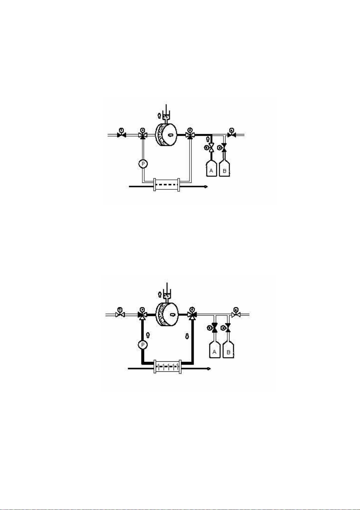
z The principle of VCS (Viscous Control System)
Dialysate mixing
As shown in the below Fig., water is supplied to the right side of the viscous chamber.
By upward movement of piston of the viscous pump during temporally stop of the water
supply, A concentrate (for bicarbonate dialysis) of a volume corresponding to the piston
stroke is aspirated in the right side. By changing the piston stroke, dialysate
concentration can be changed. During the supply and aspiration, used dialysate is
drained from the left side.
UF control
As shown in the below Fig., fresh dialysate prepared in the right side is transferred to
the left side through dialyzer by operating the pump. By upward movement of piston of
the viscous pump, capacity of closed circuit (shown as bold lines) is increased,
generating negative pressure in dialysate compartment of the dialyzer. As the result,
fluid of a volume corresponding to the piston movement is removed from blood. By
changing the piston stroke, it is possible to change UF.
The system is build up so that dialysate preparation and UF control cycle is alternating,
which means that two sets are provided in the system.
【US and JAPAN PATENTS】
4-4
Page 27

5. SPECIFICATIONS
Specification Required condition
Allowable set range
Allowable indication
range
Accuracy of indicated
value
-400~+400mmHg
Digital indication -400 to
+400mmHg
Indicator indication - -400 ~
+400mmHg
Actual pressure±10mmHg、
or ±10% (F.S.) whichever greater
No
No
Excluding indicator
5-1
Page 28

Chapter 6
INSTALLATION
Environmental condition and methods of unpacking, assembling, connection and wiring required to
install the machine and methods of disposal of used machine and packaging materials are specified
below. These operations should be performed by trained and qualified person(s) only.
6.1. Installation environment
The following requirements should be fulfilled to assure safe and effective use of the machine.
6.1.1. Ambient conditions
During :
Use Daily storage
Temp. (°C)
15 to 35 10 to 40 5 to 50 -10 to 50
Storage for one month
or more; and Transport
with contained fluid
Transport
without fluid
Relative humidity
(%)
Atmospheric
pressure (hPa)
35 to 80 15 to 85 15 to 85 15 to 85
No condensing
795 to
1062
795 to 1062 795 to 1062 700 to 1062
NOTE
Avoid direct exposure of the machine to sunlight
6.1.2. Power supply
6.1.2.1. When machine power rating is AC 230V
The machine is designed to be operated by power supply of AC 230V ± 10%, 50 Hz.
Receptacle conforming to protective earth type plug of AC rating of 230V, ≧ 10 A is required
to connect with the machine. Connect the plug with the receptacle correctly.
6.1.2.2. When machine power rating is AC 110V
The machine is designed to be operated by power supply of AC 110V ± 10%, 50 Hz.
Receptacle conforming to protective earth type plug of AC rating of 110V, ≧ 20 A is required
to connect with the machine. Connect the plug with the receptacle correctly.
6-1
Page 29

WARNING
DO NOT use AC power plug or adapter disconnecting safety earth.
DO NOT connect the machine plug to receptacle through adapter.
If power installation is suspected to have any problem, request check of wiring by electric
engineer.
6.1.3. Necessary space requirements to use the machine
Space above the top of the machine should be ≧ 5 cm, that at each of right and left sides
should be ≧ 10 cm and that at rear side should be ≧ 20 cm.
A ventilation port with a diameter ≧ 20 cm should be provided or any side other than bottom
should be cleared so that the side is completely exposed to atmosphere.
6.1.4. Water supply and drainage conditions
Water supply and drainage conditions should be checked for normal operation of the machine.
6.1.4.1. Water supply pressure
2
Pressure : 0.049 to 0.74 MPa (0.5 to 7.5 kgf/cm
)
6.1.4.2. Water supply flow rate
Flow rate : ≧ 750 mL/min
6.1.4.3. Water supply temperature
Temperature : 17 to 30 °C.
The temperature should be lower than the set dialysate temperature by ≧ 5 °C.
If heat exchanger is used, the temperature should be 5-30 °C which should be lower than the
set dialysate temperature by ≧ 5 °C.
6.1.4.4. Water quality
Supply water must be filtered through a 25 µm filter and the quality must be soft. The quality
must be monitored by regular analysis to maintain the acceptable quality.
WARNING
6-2
Use water of quality meeting AAMI - approved American National Standard for
Haemodialysis System, RD5, 1981, Section 3.2.
Otherwise, patient may suffer from seriously adverse effects.
Page 30

6.1.4.5. Concentrate line pressure
Pressure :
Min : -100 mmHg (136 cm below inlet)
Max : +100 mmHg (136 cm above inlet)
6.1.4.6. Drainage
Drain flow rate : ≧ 1500 mL/min
Drain tube tip must be placed above the machine floor by 0 to 60cm and it should not be
contacted with waste fluid level in drain groove.
6-3
Page 31

6.2. Unpacking and check of contents
WARNING
Unpacking should be performed by at least 2 operators. Otherwise bone fracture may be
caused by drop of the machine on body.
NOTE
Tightening components such as screws and nuts are mm size. If missed, use those of the
same mm size.
(1) Just after unpacking, check conformance of manufacturing No. indicated on the package to
that on the machine.
(2) Check whether the following accessories are provided and whether the machine and
accessories are not damaged.
(a) Hanger (×1)
(b) Main lamp (×1)
(c) Tray (×1)
(e) IV pole (×1)
+O-ring (×2) (d) Main lamp cap (×1)
Fig. 6-1 Accessories
6-4
Page 32

(f) Blood pump handle (×1)
(g) Coupler set (×1)
(h) Disinfectant concentrate
container connection set (×1)
(i) Dialysate concentrate container
connection set
(One for each of A and B)
(j) Dialyzer holder (×1)
(k) Tube holder (×2)
Fig.6-1 Accessories
(L) CL filter (×1)
6-5
Page 33

6.3. Procedure for assembling
6.3.1. Cautions
Take care of the followings at assembling.
(a) Place the machine on horizontal and stable floor.
(b) Sufficient space to assemble should be provided.
(c) Use accessories packaged with the machine and/or designated option to assemble.
6.3.2. Attachment of I.V. pole, hanger and main lamp
6-6
Fig. 6-2 Attachment of I.V. pole
Attach the pole to the machine as shown in Fig. 6-2. Harness can be easily passed through the pole
by binding strand to the machine side connector followed by passing the connector bound strand
through the pole. Engage the connector with the lamp side connector securely.
Wires of the both connectors are colored as shown in the below Table:
Machine side (Letters on tube) Lamp side
Black or white (LAMP) Black or white
Red Red
Page 34

6.3.3. Connector for each concentrate container
Drill concentrate container cap to prepare hole as shown in the below Fig. 6-3.
Then cut off suction port by a depth suitable for the container to make notch as shown in the
below Fig. 6-4.
Concentrate container cap
(Prepare hole of φ18.5mm)
For disinfectant concentrate For A or B concentrate
container container
Fig. 6-3 Connectors for concentrate containers
Fig. 6-4 Preparation of suction port
Cut off
Suction port
NOTE
If the container is provided with 2 ports closed with respective caps, engage the
connector with one of the ports and loosen the cap of the other port to allow air
introduction.
If the container is provided with only one port closed by one cap, engage the connector
with the port and loosen the cap to allow air introduction.
The caps (L and S) are not provided with the machine. Use L or S cap of the containers.
Prepare 3 or 4 connectors for containers receiving A, B and disinfectant concentrates;
and for container receiving acetic acid concentrate as option.
6-7
Page 35

6.4. Procedures for tube and plug connections
6.4.1. Connections of fluid supply and drain lines, coupler and power plug
CAUTION
Before and after tube and plug connection, check whether installation environment
conforms to the requirements specified in 6.1.1 of this operation manual.
Connect dialysate coupler tubes to ports “To dialyzer” and “From dialyzer” securely by
full advancing the tubes followed by banding them.
6.4.1.1. Connection of dialysate coupler tubes
(1) Connect tube at blue band side of coupler to dialysate port “To dialyzer” securely by full
advancing the tube followed by banding.
(2) Connect tube at red band side of coupler to dialysate port “From dialyzer” securely by full
advancing the tube followed by banding.
(3) Cut red band any position. Connect CL filter to cutting point followed by banding.
Connect the side of inject port for CL filter to the edge “From dialyzer”.
6.4.1.2. Connections of drain port of machine side
Use tube of an internal diameter of 8 mm and a length of 2 m or shorter to connect to the port.
Fix the connection securely by strapping with metal clip.
CAUTION
By change of height of the tube free end from drain port placed at floor, dialysate
conductivity may be changed due to change of drain pressure. If the height is changed,
check the conductivity.
6.4.1.3. Connection of water supply port
Use pressure resistant tube of an internal diameter of 8 mm.
Fix the connection securely by strapping with metal clip.
6.4.1.4. Connection of power plug
Insert power plug of the machine in receptacle securely by full advancing the plug.
6-8
Page 36

6.4.2. Connection of each concentrate
6.4.2.1. Connection to execute dialysis operation (before blood line connection)
(1) Load container of A concentrate (or acetate concentrate) and that of B concentrate on
respective container supports.
(2) Connect connectors of the machine for A and B concentrates to respective connectors of the
containers.
(3) Check whether connector of the machine for disinfectant concentrate is connected to rinse
port correctly.
(4) If acid rinse option is used, check whether connector for acetic acid concentrate is
connected to rinse port correctly.
CAUTION
Connect each concentrate connector, rinse port and the like securely. Otherwise, trouble
such as water leak or air aspiration may be caused.
During acetate dialysis (B concentrate is not used), connect connector for B concentrate
to corresponding rinse port placed at upper part of the machine.
6.4.2.2. Connection for water rinsing
(1) Check whether all connectors are connected to rinse ports.
CAUTION
Connect each concentrate connector, rinse port and the like securely. Otherwise, trouble
such as water leak or air aspiration may be caused.
Connect all 3 connectors of the machine for A, B and disinfectant concentrates to
respective rinse ports. If acid rinse option is used, connect acetic acid concentrate
connector to corresponding rinse port.
6.4.2.3. Connection for disinfection
(1) Connect connector placed at rear side of the machine for disinfectant concentrate to
container for disinfectant concentrate.
(2) Check whether connectors of the machine for A and B concentrates are connected to
respective rinse ports securely.
(3) If acid rinse option is used, check whether connector for acetic acid concentrate is
connected to rinse port correctly.
CAUTION
Connect each concentrate connector, rinse port and the like securely. Otherwise, trouble
such as water leak or air aspiration may be caused.
6-9
Page 37

6.4.2.4. Connection for acetic acid rinsing (when acid rinse option is not used)
(1) Connect connector placed at rear side of the machine for disinfectant concentrate to
container for acetic acid concentrate.
(2) Check whether connectors of the machine for A and B concentrates are connected to
respective rinse ports securely.
CAUTION
Connect each concentrate connector and the like securely. Otherwise, trouble such as
water leak or air aspiration may be caused.
6.4.2.5. Connection for acetic acid rinsing (when acid rinse option is used)
(1) Connect connector placed at rear side of the machine for acetic acid concentrate to
container for the concentrate.
(2) Check whether 3 connectors for A, B and disinfectant concentrates are connected to
respective rinse ports securely.
CAUTION
Connect each concentrate connector and the like securely. Otherwise, trouble such as
fluid leak or air aspiration may be caused.
6.4.2.6. Connection for automatic rinsing (1 or 2) (when acid rinse option is used)
(1) Connect connector placed at rear side of the machine for disinfectant concentrate to
container for the concentrate.
(2) Connect connector placed at rear side of the machine for acetic acid concentrate to
container for the concentrate.
(3) Check whether connectors of the machine for A and B concentrates are connected to
respective rinse ports securely.
CAUTION
Connect each concentrate connector, rinse port and the like securely. Otherwise, trouble
such as water leak or air aspiration may be caused.
Use disinfectant and acetic acid concentrates of specified concentrations.
6-10
Page 38

6.4.3. Air purge
The machine is shipped after filling fluid line with air. To install the machine, remove air in
accordance with the procedures shown in message screen of display. The air is removed
automatically within 7 to 10 minutes.
CAUTION
Before starting air purge, check whether water supply is enabled. If disabled, pump may
be damaged due to unloaded operation.
NOTE
When the machine is turned on after long term, date and time may be initialized and E50
RAM INITIALIZE error may be occurred to initialize SETTING 1 screen. Because RAM
back up battery is emptied. The check and re-input should be performed by well trained
person.
RAM back up battery is rechargeable. It is full charged by power on the machine about 22
hours continuously. It is emptied by turn off the machine about 7 - 10 days.
(1) Check whether all connectors are connected to respective rinse ports correctly.
(2) Check whether water can be supplied.
(3) The air purge process is enabled during rinse wait mode only. Select the mode.
(4) Press [F・5] SW to display maintenance mode menu.
(5) Press [F・3] or [F・4] SW to select "MODE9” followed by pressing [F・1] SW.
(6) After checking display of [MAINTE 9], press [F・1] SW to start the air purge process.
(7) To terminate the process forcibly during its execution, press [F・1] SW.
(8) Upon completion of the process, it is shown in the message screen.
[MAINTE MENU(4/5)]
MODE9:MACHINE FILLING PROCEDURE
MODE10:ALARM HISTORY
MODE9 MODE10 P.UP P.DOWN DISP.
F・1 F・2 F・3 F・4 F・5
[MAINTE 9]
GO TO RINSE WAITING MODE
PRESS START SW TO FILL MACHINE
STARTMENU
F・1 F・2 F・3 F・4 F・5
[MAINTE 9]
FILLING
STOP
F・1 F・2 F・3 F・4 F・5
[MAINTE 9]
END OF FILLING
MENU
F・1 F・2 F・3 F・4 F・5
6-11
Page 39

6.5. Disinfection of the dialysate circuit
Be sure to disinfect the dialysate circuit before use of the machine.
6.6. Disposal of used machine
Procedures how to dispose materials of the machine are described below:
(a) Resin such as electrical circuit board and silicone oil; rubber and electric wire should be
disposed as industrial waste. If the disposal is covered by regional regulation, dispose them
based on it.
(b) To distinguish iron from stainless steel, use magnet because the iron is attracted by it, while
the stainless steel is not so. The iron is surface finished by painting or plating to prevent rust
formation.
6.7. Disposal of used packaging materials
Dispose used packaging materials after separating to groups of wood, styrol foam, corrugated
board and the like.
6.8. Disposal of blood lines and dialyzer
Dispose used blood lines and dialyzer by suitable manners specified by hospital or medical
facilities to prevent risk of infection.
6-12
Page 40

Chapter 7
MAIN FUNCTIONS AND COMPONENTS
Main functions and components of the machine are as follows:
(1) Preparation of bicarbonate dialysate
(2) Preparation of acetate dialysate
(3) Ultrafiltration control by viscous control system (VCS)
(4) Sequential dialysis
(5) One clamp single needle dialysis
(6) Rinsing program
(7) Blood pump (three roller type)
(8) Bubble detector
(9) Clamp
(10) Auto self check
(11) Blood leak detector
(12) Auto gas purge
(13) Message screens of display
(14) Auto priming
(15) Drain from dialyzer
(16) Check of leak from closed circuit
(17) Main lamp
(18) Double syringe pump
(19) Arterial pressure sensor (option)
(20) Backup for blood pump at power failure (option)
(21) Heat exchanger (option)
(22) Acid rinse port (option)
(23) Hot rinse-programming (option)
7-1
Page 41

Chapter 8
CONSTRUCTION OF MACHINE
8.1 Overall construction
8.1.1 Overall views
Main
Operation
Blood line setting
Front view
Fig. 8-1-1 Front and right side views of SURDIAL
8-1
Right side
Page 42

y
Power suppl
Rear side view Left side view
Fig. 8-1-2 Rear and left side views of SURDIAL
8-2
Page 43

V
8.1.2 Components of machine and their purposes and functions
No. Component Purpose and function
1 Sampling port
2 Rinse port for A
concentrate
3 Connector for A
concentrate
4 Rinse port for B
concentrate
5 Connector for B
concentrate
6 Flow meter
7 Dialysate return tube Tube used to return used dialysate to port “From
8 Dialysate supply tube Tube used to supply fresh dialysate to port “To
9 Dialysate return coupler
10 Dialysate supply coupler Coupler used to connect fresh dialysate supply tube to
11 Bypass connector Connector used to bypass ports “From Dialyzer” and
12 Limit SW for bypass
connector
13 Coupler holder
14 Dialysate flow rate
regulating needle valve
15 Container support
16 Port “From Dialyzer”
17 Port “To Dialyzer”
Port used to take dialysate sample
Port used to connect to connector of A concentrate
container during rinsing operation
Connector used to connect connector of bicarbonate A
concentrate container
Port used to connect connector of B concentrate
container during rinsing operation
Connector used to connect connector of bicarbonate B
concentrate container
Meter use to indicate flow rate of dialysate supplied to
dialyzer
Dialyzer”
Dialyzer”
Coupler used to connect used dialysate return tube to
dialyzer
dialyzer
“To Dialyzer” when couplers Nos. 9 and 10 are set to
the machine during rinsing operation
SW used to detect whether coupler is received in
coupler holder
Holder used to receive coupler during rinsing operation
alve used to regulate dialysate flow rate in closed
circuit
Support used to load dialysate concentrate container
Port used to return used dialysate from dialyzer
Port used to supply fresh dialysate to dialyzer
8-3
Page 44

No. Component Purpose and function
18 Water supply port
19 Drain port
20 Port for connector of
disinfectant concentrate
connector
21 Connector for disinfectant
concentrate container
22 Blood leak sensor
23 Priming flow rate regulating
needle valve
24 Tray
Port used to connect hose for supplying purified water
to the machine
Port used to connect hose for draining used dialysate
Port use to connect connector of disinfectant
concentrate container when disinfectant or acid rinsing
is not executed
Connector used to connect disinfectant concentrate
container during disinfection/rinsing; or that used to
connect
acetic acid concentrate container during acid rinsing
Sensor used to detect blood leak
Valve used to regulate flow rate of priming solution
Tray used to hold tools during dialysis by placing it on
the machine top
8-4
Page 45

8.2 Operation panel
8.2.1 Construction of operation panel
Fig. 8-2 Operation panel
8-5
Page 46

8.2.2 Components of operation panel and their purposes and functions
No. Component Purpose and function
1 [DIALYSIS] SW with lamp SW used to start dialysis
“During dialysis preparation” and “enabled dialysis
start” is indicated by lamp lighting.
2 [PREP.] SW with lamp SW used to prepare dialysate and to prepare to start air
purge
“Preparation end” or “during recovery” is indicated b y
lamp lighting.
“During preparation” is indicated by lamp flashing.
3 [UF DIALYSE] SW with
lamp
4 [BYPASS] SW with lamp SW used to bypass dialysate without passing through
5 [DRAIN] SW
6 [RINSE] SW with lamp SW used to start rinsing of fluid lines of the machine
7 CONDITION lamp Lamp used to indicate operating condition
8 [MUTE] SW with lamp “Alarm actuation” is indicated by lamp lighting. By
9 [RESET] SW with lamp “Alarm actuation” is indicated by lamp lighting. By
10 POWER lamp
11 Display Display used to show dialysate temperature, VP, DP and
12 Venous pressure indicator Indicator used to show VP by bar graph
13 Set upper VP limit
increasing SW
14 Set upper VP limit
decreasing SW
SW used to start UF
“During UF” is indicated by lamp lighting.
dialyzer
“During manual bypassing” is indicated by lamp
lighting.
“During automatic bypassing” is indicated by lamp
flashing.
SW used to drain dialysate from dialyzer
“During rinsing” is indicated by lamp lighting.
“During UF” is indicated by green lighting and “during
alarm actuation” is indicated by red lighting.
pressing SW, buzzing is muted and lamp is OFF.
pressing SW after muting buzzer, alarm is released and
lamp is OFF.
“Power SW ON” is indicated by lamp lighting.
alerted condition, etc. for monitoring them.
Upper and lower limits of set VP range are also shown
by different colors.
SW used to increase set upper VP limit within
acceptable range
SW used to decrease set upper VP limit within
acceptable range
8-6
Page 47

No. Component Purpose and function
15 Set lower VP limit
increasing SW
16 Set lower VP limit
decreasing SW
SW used to increase set lower VP limit within
acceptable range
SW used to decrease set lower VP limit within
acceptable range
17 DP/AP indicator Indicator used to show DP or AP (option) by bar graph
Upper and lower limits of set DP or AP range are also
shown by different colors.
18 DP indication lamp Lamp used to indicate that DP is shown in DP/AP
indicator
19 AP indicator lamp Lamp used to indicate that AP is shown in DP/AP
indicator
20 Set upper DP/AP limit
increasing SW
21 Set upper DP/AP limit
decreasing SW
22 Set lower DP/AP limit
increasing SW
23 Set lower DP/AP limit
decreasing SW
SW used to increase set upper DP or AP limit within
acceptable range
SW used to decrease set upper DP or AP limit within
acceptable range
SW used to increase set lower DP or AP limit within
acceptable range
SW used to decrease set lower DP or AP limit within
acceptable range
24 Conductivity indicator Indicator used to show conductivity by bar graph
Upper and lower limits of set conductivity range are
also shown by different colors.
25 Total UF volume indicating
LED
26 [UF RESET] SW
LED used to indicate total UF volume at this time
digitally
SW used to reset total UF volume indicating LED
27 Target UF volume
LED used to indicate set target UF volume digitally
indicating LED
28 Set target UF volume
SW used to increase set target UF volume
increasing SW
29 Set target UF volume
SW used to decrease set target UF volume
decreasing SW
30 UFR indicating LED
LED used to indicate set UFR digitally
31 Set UFR increasing SW
SW used to increase set UFR
32 Set UFR decreasing SW
SW used to decrease set UFR
33 Left time indicating LED
LED used to indicate left dialysis time at this time
digitally
8-7
Page 48

No. Component Purpose and function
34 Set left time increasing SW SW used to increase displayed left dialysis time
digitally
35 Set left time decreasing SW SW used to decrease displayed left dialysis time
digitally
36 FUNCTION 1 SW SW used to set various parameters
Set data is indicated in message screen.
37 FUNCTION 2 SW SW used to set various parameters
Set data is indicated in message screen.
38 FUNCTION 3 SW SW used to set various parameters
Set data is indicated in message screen.
39 FUNCTION 4 SW SW used to set various parameters
Set data is indicated in message screen.
40 FUNCTION 5 SW SW used to set various parameters
Set data is indicated in message screen.
41 Bubble sensor activating
SW with lamp
42 Syringe pump fast infusion
SW use to activate bubble sensor
Sensor activation is indicated by lamp lighting.
SW use to operate syringe pump at fast infusion rate
SW
43 Syringe pump flow rate
LED used to indicate flow rate of syringe pump digitally
indicating LED
44 Set syringe pump flow rate
SW used to increase set syringe pump flow rate
increasing SW
45 Set syringe pump flow rate
SW used to decrease set syringe pump flow rate
decreasing SW
46 Syringe pump operating
SW with lamp
47 Blood pump flow rate
SW used to operate syringe pump
Pump operation is indicated by lamp lighting.
LED used to indicate BP flow rate digitally
indicating LED
48 Blood pump flow rate
Volume used to set BP flow rate
setting
volume
49 Blood pump operating SW
with lamp
SW used to operate blood pump
Pump operation is indicated by lamp lighting.
8-8
Page 49

8.3 Blood line setting panel
8.3.1 Construction of blood line setting panel
Fig. 8-3 Blood line setting panel
8-9
Page 50

8.3.2 Components of blood line setting panel and their purposes and
functions
No. Component Purpose and function
1 Blood pump rotor Rollers used to deliver blood by squeezing blood line
tube
2 Blood pump cover Cover used to protect rotating mechanism of BP
BP operation stop is caused by opening cover.
3 Blood pump cover SW SW used to monitor opening of BP cover
4 Bubble detector Detector used to detect bubble in blood line
5 Clamp Clamp used to close blood line tube for blood flow stop
6 Tube holder Holder used to set blood line tube
7 Venous pressure inlet port Port used to introduce venous pressure for its
measurement
8 Pusher Used to advance syringe plunger
Engageable with the plunger by receiving its flange in it
Release of lock by pushing in, enabling manual right or
left movement
9 Syringe holder Used to hold syringe
10 Syringe holding lever Used to hold syringe in syringe holder by rotation
Syringe holding by rotating it to cross syringe and
release of the holding by parallel placement of it with
syringe
8-10
Page 51

8.4 Power supply
8.4.1 Construction of power supply
Fig. 8-4 Power supply
8-11
Page 52

8.4.2 Components of power supply and their purposes and functions
No. Component Purpose and function
1 Power cord Cord having power plug at its distal end
2 Power SW Power SW of the machine
3 Buzzer Buzzer used to alert error audibly
4 DC24V OUT Service connector for manufacture
5 RS-232C Service connector for manufacture
6 BP BACKUP Volume used to set BP flow rate at power failure
(Enabled only when required option is used)
7 Fan Fan used to ventilate power box inside
8 Air filter Filter used to remove dust from air introduced into
Electrical POWER BOX.
8-12
Page 53

8.5 Main lamp assembly
8.5.1 Construction of main lamp assembly
Fig. 8-5 Main lamp assembly
8-13
Page 54

8.5.2 Components of main lamp assembly and their purposes and functions
No. Component Purpose and function
1 Main lamp
2 Hanger
3 I.V. pole
4 Set screw
O-ring (×2)
5
6 Main lamp cap
Lamp used to alert error visually
Hanger used to suspend vial and the like
Pole used to hold dialyzer and the like
Screw used to fix hanger to I.V. pole
Rings used to cushion fixed hanger
Cap used to support main lamp
8-14
Page 55

Chapter 9
DISPLAY
LCD is used to display various dialysis related information and parameter setting screens in
area of 40 letters×4 lines.
Many information and parameter setting screens are available. Desired mode screen can be
displayed by SW operation on operation panel.
[F・5] SW (DISP.) Rinsing operation screen (9.3) [F・5] SW (DISP.)
Dialysis operation screen (9.4)
SettingⅠscreen (9.5) Alarm screen (9.8)
※ Only when alarm is actuated
[F
5] SW (DISP.)
・
[F
・
5] SW (DISP.)
SettingⅡscreen (9.6) Maintenance
[F・5] (DISP.) SW menu screen (9.7)
[F
(MODE
1][F
2] SW
*
)
…See “Service Manual”. Maintenance
1-10 screens
Fig. 9-1 Screen flow
・
・
[F
5] SW (MENU)
・
9-1
Page 56

CAUTION
z LCD is easily damaged. Do not press or scratch its surface by pencil point or any hard
tool.
z LCD is mainly constructed by glass. Do not give impact to it.
z Do not press operation panel SW by pencil point or any hard tool.
9-2
Page 57

9.1. Layout of display
Areas from①to⑨are allocated to LCD screen to display information specified for each of
them.
① ② ③
④
⑤ ⑥ ⑦ ⑧ ⑨
Fig. 9.2 Layout of display
① Title display area
Title of currently selected mode is displayed.
② Operation display area 1
One of operation types such as SINGLE.N and SQHD is displayed as shown in the left
side of the below Table. Procedure to display each of the types is shown in the right side
of the Table.
SINGLE.N Turn on single needle SW.
SQHD Turn on sequential HD SW.
CONSOLE Select console mode in maintenance mode 7.
ERR FREE Release any of alarms in maintenance mode 3.
③ Operation display area 2
One of operation types such as draining and UF is displayed as shown in the left side of
the below Table. Condition required to display each of the types is shown in the right side
of it.
UF During UF execution.
BP Stop During BP SW is ON, while BP is stopped.
Drain During draining.
FlowStop During fluid flow stop due to alarm actuation.
GasParge During gas purging (excluding dialysis process).
Standby During preparation process
Bypass During bypassing (excluding auto bypass in dialysis wait
process)
MIN.UF During minimum UF execution
Wait During rinse wait process
Rinse During rinse process
End During rinse end process
④ Setting/information display area
Rinse screen (rinse wait, rinse, rinse end wait), dialysis screen (dialysis wait,
9-3
Page 58

preparation, preparation end, dialysis, recovery) and various setting screens (settingⅠ,
settingⅡ, maintenance) are displayed.
9-4
Page 59

⑤ [F・1] SW function display area
[F・1] SW functions are displayed.
⑥ [F・2] SW function display area
[F・2] SW functions are displayed.
⑦ [F・3] SW function display area
[F・3] SW functions are displayed.
⑧ [F・4] SW function display area
[F・4] SW functions are displayed.
⑨ [F・5] SW function display area
[F・5] SW functions are displayed.
9-5
Page 60

9.2 Wake up screen
This screen is displayed for several seconds by turning on power SW.
SINGLE PATIENT DIALYSIS MACHINE
SURDIAL TYPE Ⅱ
NIPRO CORPORATION RAM:OK
ROM Ver.3.00/01 ROM:OK
Fig. 9-3 Rise screen
INDICATION DESCRIPTION
SINGLE PATIENT DIALYSIS MACHINE Machine name
SURDIAL Machine type
NIPRO CORPORATION Manufacturer name
ROM Ver. ROM version No.
RAM RAM check result
ROM ROM check result
CAUTION
z Any specifications and functions may not be provided according to the machine version
No. To know the details, contact our branch or representative near your place.
9-6
Page 61

9.3 Rinse screen
9.3.1 Rinse menu
Rinse menu is used to select and register rinse mode.
Press any of [F・1] to[F・4] SW’s to select desired rinse mode.
Press [F・5] SW to display settingⅠscreen.
[RINSE MENU]
RINSE1:WATER RINSE3:AUTO1 C&D
RINSE2:CHEMICAL RINSE4:AUTO2 C&D
RINSE1 RINSE2 RINSE3 RINSE4 DISP.
Fig. 9-2 Rinse menu screen
INDICATION DESCRIPTION
RINSE1:WATER Mode to execute water rinse only
RINSE2:CHEMICAL Mode to execute disinfection/rinse only
RINSE3:AUTO1 C&D Mode to execute programmed rinse
RINSE4:AUTO2 C&D Mode to execute programmed rinse
9-7
Page 62

9.3.2 Rinse wait
When rinse wait mode is selected, rinse mode and time to be executed are displayed.
Information displayed together with the mode and time is defined by selected rinse mode.
9.3.2.1 RINSE1: WATER
Press [F・1] or [F・2] SW to change rinse time only.
Press [F・5] SW to display rinse menu.
[RINSE1] 20:15 < Wait >
WATER RINSE 30min
+ - MENU
Fig. 9-5 Rinse wait screen when RINSE1 is selected
9.3.2.2 RINSE2:CHEMICAL
Press [F・1] or [F・2] SW to change rinse time only.
[RINSE2] 20:15 < Wait >
CHEMICAL RINSE 30min
+ - MENU
Fig. 9-6 Rinse wait screen when RINSE2 is selected
9.3.2.3 RNSE3:AUTO1 C&D
Press [F・3] or [F・4] SW to shift blink to desired position and press [F・1] or [F・2] SW to
change setting.
Details are same as the case of『RINSE4:AUTO2 C&D』.
[RINSE3] 20:15 < Wait >
WTR30→CHM30→DWL30→PRE30→-----→-----
PRERINSE START TOMORROW 10:00
+ - < > MENU
Fig. 9-7 Rinse wait screen when RINSE3 is selected
9-8
Page 63

9.3.2.4 RINSE4: AUTO2 C&D
Press [F・3] or [F・4] SW to shift blink to desired position and press [F・1] or [F・2] SW to
change setting.
Rinse program and time can be changed.
[RINSE4] 20:15 < Wait >
WTR30→CHM30→DWL30→PRE30→-----→-----
PRERINSE START TOMORROW 10:00
+ - < > MENU
Fig. 9-8 Rinse wait screen when RINSE4 is selected
INDICATION DESCRIPTION
WTR※※ Execution of water rinse for ※※ min
CHM※※ Execution of disinfection/rinse for ※※ min
ACD※※ Execution of acid rinse for ※※ min
DWL※※ Execution of dwelling for ※※ min
PRE※※
-----
PRERINSE START Setting of prerinse start time within period from this
Start of prerinse at time set by PRERINSE START
No operation
time to 6 days after it
NOTE
z If acid rinse port unit (option) is not set to the machine, simultaneous setting of both
disinfection/rinse and acid rinse is disabled.
z If program adversely affecting the machine operation; for example, program to execute
disinfection/rinse and acid rinse in sequence; or that including no prerinse or no water
rinse step after rinse completion is set, rinsing operation can not be started even by
pressing RINSE SW.
z Refer to the option manual for setting hot rinse function. Set up hot water rinse (HWR)
and hot chemical disinfectant rinse require the machine already have hot rinse option.
9-9
Page 64

9.3.3 Rinse execution
During rinse progress, rinse step at that time is displayed. Displayed information is defined
by selected rinse mode.
NOTE
z If any SW on operation panel is not pressed for ≧30 minutes during prerinse wait
process, back light is automatically turned off. By pressing the SW or by starting prerinse,
the light is ON.
9.3.3.1 RINSE1: WATER
By rinse advancement, indicated rinse time is reduced to show left rinse time.
Press [F・5] SW to display settingⅠscreen.
[RINSE1] 20:30 < Rinse >
WATER RINSE 15min
DISP.
Fig. 9-9 Rinse execution screen when RINSE1 is selected
9.3.3.2 RINSE2: CHEMICAL
By rinse advancement, indicated rinse time is reduced to show left rinse time.
[RINSE2] 20:30 < Rinse >
CHEMICAL RINSE 15min
DISP.
Fig. 9-10 Rinse execution screen when RINSE2 is selected
9.3.3.3 RINSE3: AUTO1 C&D
Currently executed rinse step is double blinked. By rinse advancement, indicated rinse time
is reduced to show left rinse time.
[RINSE3] 21:00 < Rinse >
WTR00→CHM15→DWL30→PRE30
PRERINSE START TOMORROW 10:00
DISP.
Fig. 9-11 Rinse execution screen when RINSE3 is selected
9.3.3.4 RINSE4: AUTO2 C&D
Currently executed rinse step is double blinked. By rinse advancement, indicated rinse time
is reduced to show left rinse time.
[RINSE4] 21:00 < Rinse >
WTR00→CHM15→DWL30→PRE30
PRERINSE START TOMORROW 10:00
DISP.
9-10
Page 65

Fig. 9-12 Rinse execution screen when RINSE4 is selected
9-11
Page 66

9.3.4 Rinse end
During rinse end process, rinse result is displayed. Displayed information is defined by
selected mode.
NOTE
z If any SW on operation panel is not pressed for ≧30 minutes during rinse end screen is
displayed, back light is automatically turned off. By pressing the SW, the light is ON.
9.3.4.1 RINSE1: WATER
Rinse time of 00 min is displayed to indicate fluid line function stop.
Press [F・5] SW to display settingⅠscreen.
[RINSE1] 20:45 < End >
WATER RINSE 00min
DISP.
Fig. 9-13 Rinse end screen when RINSE1 is selected
9.3.4.2 RINSE2:CHEMICAL
Rinse time of 00 min is displayed to indicate fluid line function stop.
[RINSE2] 20:45 < End >
CHEMICAL RINSE 00min
DISP.
Fig. 9-14 Rinse end screen when RINSE2 is selected
9.3.4.3 RINSE3:AUTO1 C&D
Rinse time of 00 min is displayed to indicate fluid line function stop.
[RINSE3] 10:40 < End >
WTR00→CHM00→DWL00→PRE00
PRERINSE START TODAY 10:00
DISP.
Fig. 9-15 Rinse end screen when RINSE3 is selecetd
9.3.4.4 RINSE4:AUTO2 C&D
Rinse time of 00 min is displayed to indicate fluid line function stop.
[RINSE4] 10:40 < End >
WTR00→CHM00→DWL00→PRE00
PRERINSE START TODAY 10:00
DISP.
Fig. 9-16 Rinse end screen when RINSE4 is selected
9-12
Page 67

9.4 Dialysis screen
9.4.1 Dialysis
Part of dialysis related information is displayed during dialysis wait, preparation, preparation
end, dialysis and recovery processes.
Press [F・1] SW to select single needle dialysis mode.
Press [F・2] SW to select sequential HD mode.
Press [F・3] SW to select priming mode.
Press [F・4] SW to select test mode.
Press [F・5] SW to display settingⅠscreen.
[DIALYSIS]
VP: 140mmHg DP: 100mmHg COND:14.0mS/cm
AP:-100mmHg TMP: 40mmHg TEMP:37.0゜C
S.N. SQHD PRIM TEST DISP.
Fig. 9-17 Dialysis screen
INDICATION DESCRIPTION
VP Current venous pressure
AP Current arterial pressure
Displayed only when required option is used
DP Curr ent dialysate pressure
TMP Current TMP
COND Current conductivity
TEMP Current dialysate temperature
NOTE
z Select this screen during dialysis.
z Also refer to information found on operation panel.
z Information not found in this screen is shown in maintenance mode 1 screen.
9-13
Page 68

9.4.2 Priming
Priming screen is used to set auto priming conditions and to indicate each step during
priming operation.
Press [F・1] or [F・2] SW to change target priming volume. Press [F・4] SW to release from
priming mode.
Press [F・5] SW to display settingⅠscreen.
[PRIMING]
SOLUTION VOL.(l):5.00
ACCUMULATED VOL.(l):5.00 RATIO(%):100
+ - EXIT DISP.
Fig. 9-18 Priming screen
INDICATION DESCRIPTION
SOLUTION VOL. Setting of target priming solution volume
ACCUMULATED VOL. Display of used priming solution volume
RATIO Display of priming progress by ratio
9-14
Page 69

9.4.3 Test mode
Simple self diagnosis parameters and results are displayed.
Press [F・4] SW to release from test mode.
Press [F・5] SW to display settingⅠscreen.
[TEST]
BP:OK CLV:OK BD: VPa: VPb:
VP: AP:
EXIT DISP.
Fig. 9-19 Test mode screen
INDICATION DESCRIPTION
BP Display of BP test result by OK or NG
CLV Display of clamp test result by OK or NG
BD Display of bubble sensor test result by OK or NG
VPa Display of viscous pump a test result by OK or NG
VPb Display of viscous pump b test result by OK or NG
VP Display of venous pressure sensor test result by OK
or NG
AP Display of arterial pressure sensor test result by OK or
NG when required option is set
NOTE
z The self diagnosis is simple. Accordingly, all required checks can not be performed.
z The diagnosis is performed under specified conditions. If the conditions are not satisfied,
NG may be resulted.
9-15
Page 70

9.5 SettingⅠ screen
Part of required settings is displayed.
Press [F・3] or [F・4] SW to shift blink to desired position and press [F・1]or [F・2] SW to
change setting.
The setting change is enabled at any time required.
Press [F・5] SW to display settingⅡscreen.
[SETTING1]
1.TEMP (°C):37.0 2.BAR GRAPH :DP
3.S.STP(min): 0 4.BOLUS (ml):0.0
+ - < > DISP.
Fig. 9-20 SettingⅠ screen
INDICATION DESCRIPTION
1.TEMP Setting of dialysate temperature
2.BAR Changeover of DP and AP in DP/AP indicator
DP: Dialysate pressure AP: Arterial pressure
Blinking only when AP option is set
3.S.STP Setting of syringe stop time (from infusion end to UF
end)
Displayed only when required option is set.
4.BOLUS Setting of one shot infusion volume
Infusate of the set volume is infused automatically by
pressing FAST SW of syringe pump.
Displayed only when required option is set.
NOTE
z Settings not found in this screen are shown in settingⅡscreen and maintenance mode 2,
5, 6 and 7 screens.
9-16
Page 71

9.6 SettingⅡ screen
Part of required settings is displayed.
Press [F・3] or [F・4] SW to shift blink to desired position and press [F・1]or [F・2] SW to
change setting.
The setting change is enabled at any time required.
Press [F・5] SW to display maintenance mode menu.
[SETTING2]
1.BC(W+A+B) :140 2.BC(W+A) :110
3.AC(W+AC) :140 4.MODE :BC1
+ - < > DISP.
Fig. 9-21 SettingⅡscreen
INDICATION DESCRIPTION
1.BC(W+A+B) Setting of final bicarbonate dialysate at mmol/l unit
2.BC(W+A) Setting of [water + A concentrate] concentration in
bicarbonate dialysate at mmol/l unit
3.AC(W+AC) Setting of final acetate dialysate concentration at
mmol/l unit
4.MODE Selection of dialysis mode corresponding to actually
used concentrate. Information related to the
concentrate is shown in maintenance mode 5 screen.
BC1: Bicarbonate dialysis
BC2: Bicarbonate dialysis
AC: Acetate dialysis
NOTE
z Settings not found in this screen are shown in settingⅡscreen and maintenance mode 2,
5, 6 and 7 screens.
9-17
Page 72

9.7 Maintenance menu screen
The screen is used to select and register maintenance mode.
Press [F・3] or [F・4] SW to changeover screen and press [F・1] or [F・2] SW to select desired
mode.
Press [F・5] SW to display rinse or dialysis screen. During alarm is actuated, the alarm
screen is displayed.
[MAINTE MENU(1/5)]
MODE1:DATA
MODE2:ALARM SETTING
MODE1 MODE2 P.UP P.DOWN DISP.
Fig. 9-22 Maintenance mode menu screen
9-18
Page 73

9.8 Alarm screen
The screen is displayed when alarm is actuated.
Press [F・3] or [F・4] SW to find alarm characteristic.
Press [F・5] SW to display rinse or dialysis screen.
[ERROR](10)
1.E24 AIR BUBBLE ARE DETECTED
2.E26 SHORT WATER SUPPLY
UP DOWN DISP.
Fig. 9-23 Alarm screen
9-19
Page 74

Chapter 10
ALARM FUNCTIONS AND RESETTING
When any error is detected by the machine, it is alerted by lighting of condition and main
lamps with buzzing and the alarm related message is displayed in relevant screen. According
to severity of the alarm, corrective functions such as the machine stop is executed
automatically by safety system contained in the machine.
WARNING
z If any error is alerted repeatedly, stop the machine to discontinue dialysis immediately
and disconnect patient from the machine. Otherwise, the patient may suffer from serious
injury.
10.1 Description of alarms
10.1.1 Functions when error is alerted
If operation is notified of any error incidence, one or more of the following functions
(a) to (j) are executed according to alarm type.
In the case that plural functions are executed, see 10.2.2 “Table of Alarms” to know
the combined functions.
(a) Alarm message display
Alarm No. and message are displayed in alarm message screen. One message is
displayed as one line and 2 messages can be displayed simultaneously. If 3 or
more of errors are detected, scroll the screen to find other alarm No. and message
by pressing [F・3] or [F・4] SW.
(b) Audible alarm
Buzzing is caused together with lighting of [MUTE] SW and [RESET] SW lamps on
operation panel.
(c) Condition lamp
Red lighting
(d) Main lamp
Red flashing
(e) Fluid line stop
Fluid flow is disabled by stop of P1 and P2 pumps and heater is turned off.
(f) UF stop
UF operation is disabled by stop of viscous pump. (UF operation may be continued at
low UFR as “minimum UF” function.)
(g) Automatic bypassing
Coupler lines are bypassed to stop dialysate supply to dialyzer.
10-1
Page 75

(h) Blood or heparin pump stop
Blood or heparin pump is stopped.
(i) Clamping
When dialysate pressure related error or bubble in blood line is detected, the line
is clamped temporarily.
(j) Dialysate pressure release or air removal from dialysate
When dialysate pressure exceeds preset level, it is alerted and the pressure is
released automatically. When air is detected in dialysate lines during dialyzer
connection, the air is automatically removed.
10.1.2 Procedure for resetting
To return the machine functions to normal after removal of error causes, follow the
below procedures. See 10.2.2 “Table of Alarms” to find the error causes and the like.
① Press [MUTE] SW once.
• Audible alarm is muted.
• [MUTE] SW lamp is OFF.
② Remove error causes.
③ Press [RESET] SW once.
• [RESET] SW lamp is OFF.
• The machine functions are returned to normal.
10.1.3 Actions to respond to alarm (flow)
Error incidence
↓
Detection of error and execution of machine functions responding to the error
↓
Buzzing OFF by operator
↓
Removal of error causes by operator
↓
Resetting by operator
10-2
Page 76

10.2 Table of alarms
10.2.1 Meanings of terms contained in “Table of alarms”
(1) Alarm No.
Alarm No. indicated in alarm screen
(2) Alarm name
Alarm name indicated in alarm screen
(3) Detection condition
Condition to be detected. Unless otherwise specified, it is recognized as alarm when
the condition continues for specified time (1 to 5 seconds). The time is defined by alarm
type.
(4) Detection process
Process in which error is detected
(5) Audible alarm
When buzzing is caused after error detection, "○" is marked. If bussing is muted
after specified number of runs automatically, the number is indicated. If the alarm
condition is specified by any detection process, the condition and the process aligned
horizontally are marked with "・".
(6) Fluid line function
Fluid line function after error detection. If the function is specified by any detection
process, the function and the process aligned horizontally are marked with "・". If the
function is not changed after the detection, "-" is marked.
(7) BP/SP stop
When blood or syringe pump is stopped by error detection, "○" is marked. If the
pump is stopped for specified time, the time is indicated. When blood pump only is
stopped , "BP stop" and when syringe pump only is stooped, "SP stop" is indicated.
(8) CLV close
When blood line is clamped b y error detection, "○" is marked. If the line is clamped
for specified time, the time is indicated and if not clamped, "-" is marked.
(9) Alarm release
When alarm release is enabled, "○" is marked and when disabled, "-" is marked. In
the former case, the release is possible in maintenance mode 3 and part of alarms can
be released by erasing the set alarm value.
(10) Resetting and note
Alarm resetting method and note. Almost all alarms can be reset by pressing [RESET] SW.
10-3
Page 77

Part of alarms may be reset by release of the alarm from detection condition.
10-4
Page 78

10.2.2 Table of alarms
Alarm
No.
E01 RECOVER FROM
E02 T1 TEMPERATURE
E03 T2 TEMPERATURE
E04 T3 TEMPERATURE
E05 DIALYSATE
Alarm name
EMERGENCY STOP
SENSOR ERROR
SENSOR ERROR
SENSOR ERROR
TEMPERATURE
MAX ALARM
Return to normal after
power failure caused
during sequence
execution
T1 temperature exceeding
measurable temperature
T2 temperature exceeding
measurable temperature
T3 temperature exceeding
measurable temperature
Dialysate temperature (T3)
of ≧ set upper alarm limit
Detection
condition
Detection
process
•Rinse
•Preparation
•Preparation end
•Dialysis
•Recovery
•Rinse wait
•Rinse
•Rinse end
•Air purge
•Dialysis wait
•Preparation
•Preparation end
•Dialysis
•Recovery
•Rinse wait
•Rinse
•Rinse end
•Air purge
•Dialysis wait
•Preparation
•Preparation end
•Dialysis
•Recovery
•Rinse wait
•Rinse
•Rinse end
•Air purge
•Dialysis wait
•Preparation
•Preparation end
•Dialysis
•Recovery
•Preparation
•Preparation end
•Dialysis
•Recovery
Audible alarm
○(3 times)
•○(7 times)
•Same as above
•Same as above
•Same as above
•○(Continuous)
•Same as above
•Same as above
•Same as above
•Same as above
•○(7 times)
•Same as above
•Same as above
•Same as above
•○(Continuous)
•Same as above
•Same as above
•Same as above
•Same as above
•○(7 times)
•Same as above
•Same as above
•Same as above
•○(Continuous)
•Same as above
•Same as above
•Same as above
•Same as above
○(Continuous)
Fluid line
function
Execution of
sequence before
error detection
•Continuance
•Same as above
•Same as above
•Same as above
•Same as above
•Fluid line stop
•Same as above
•Same as above
•Same as above
•Continuance
•Same as above
•Same as above
•Same as above
•Same as above
•Fluid line stop
•Same as above
•Same as above
•Same as above
•Continuance
•Same as above
•Same as above
•Same as above
•Same as above
•Fluid line stop
•Same as above
•Same as above
•Same as above
Auto bypass
Heater OFF
BP
SP
stop
― ― ―
― ― ○
― ― ○
― ― ○
― ― ○
CLV
close
Alarm
release
Resetting and note
Automatic return to normal
Becoming error free of set upper and lower
VP/ AP/ DP alarm limits by alarm actuation
Return to normal by pressing [RESET] SW
Return to normal by pressing [RESET] SW
During rinse process, upper value of
measurable range could not be detected.
[Return to normal by pressing [RESET] SW
Return to normal by pressing [RESET] SW
Auto reset after release from detection
condition for 10 sec
10-4
Page 79

Alarm
No.
E06 DIALYSATE
E07 DIALYSATE PRESSURE
E08 DIALYSATE PRESSURE
E09 DIALYSATE PRESSURE
E10 DIALYSATE PRESSURE
E11 VENOUS PRESSURE
Alarm name
TEMPERATURE
MIN ALARM
MAX LIMIT
MIN LIMIT
MAX ALARM
MIN ALARM
MAX LIMIT
Detection
condition
Dialysate temperature (T3)
of ≦set lower alarm limit
Dialysate pressure of
≧+400mmHg
Dialysate pressure of
≦-400mmHg
Dialysate pressure of ≧
set upper alarm limit
Dialysate pressure of ≦
set lower alarm limit
Venous pressure of
≧+400mmHg
Detection
process
Dialysis
•Rinse wait
•Rinse
•Rinse end
•Air purge
•Dialysis wait
•Preparation
•Preparation end
•Dialysis
•Recovery
•Rinse wait
•Rinse
•Rinse end
•Air purge
•Dialysis wait
•Preparation
•Preparation end
•Dialysis
•Recovery
•Dialysis wait
•Preparation
•Preparation end
•Dialysis
•Recovery
•Dialysis wait
•Preparation
•Preparation end
•Dialysis
•Recovery
•Rinse wait
•Rinse
•Rinse end
•Air purge
•Dialysis wait
•Preparation
•Preparation end
•Dialysis
•Recovery
Audible alarm
○(3 times)
•○(7 times)
•Same as above
•Same as above
•Same as above
•○(Continuous)
•Same as above
•Same as above
•Same as above
•Same as above
•○(7 times)
•Same as above
•Same as above
•Same as above
•○(Continuous)
•Same as above
•Same as above
•Same as above
•Same as above
○(Continuous)
○(Continuous)
•○(7 times)
•Same as above
•Same as above
•Same as above
•○(Continuous)
•Same as above
•Same as above
•Same as above
•Same as above
Fluid line
function
Auto bypass
UF stop
V4,V10 ON for 2
sec
UF stop
V4,V10 ON for 2
sec
UF stop
V4,V10 ON for 2
sec
UF stop
V4,V10 ON for 2
sec
UF stop
BP
SP
stop
― ― ○
2 sec 2 sec
2 sec 2 sec
2 sec 2 sec
2 sec 2 sec
○ ― ○
CLV
close
release
Alarm
○
○
○
○
Resetting and note
Return to normal by pressing [RESET] SW
Auto reset after release from detection
condition for 10 sec
Auto return of BP/SP/CLV to normal
Return of UF stop to normal by pressing
[RESET] SW
Auto return of BP/SP/CLV to normal
Return of UF stop to normal by pressing
[RESET] SW
Auto return of BP/SP/CLV to normal
Return of UF stop to normal by pressing
[RESET] SW
Becoming error free of set upper and lower
VP alarm limits by alarm actuation
Auto return of BP/SP/CLV to normal
Return of UF stop to normal by pressing
[RESET] SW
Becoming error free of set upper and lower
VP alarm limits by alarm actuation
Return to normal by pressing [RESET] SW
10-5
Page 80

Alarm
No.
E12 VENOUS PRESSURE MIN
E13 VENOUS PRESSURE
E14 VENOUS PRESSURE MIN
E15 ARTERIAL PRESSURE
E16 ARTERIAL PRESSURE
Alarm name
LIMIT
MAX ALARM
ALARM
MAX LIMIT
MIN LIMIT
Detection
condition
Venous pressure of
≦-400mmHg
Venous pressure of ≧set
upper alarm limit
Venous pressure of ≦set
lower alarm limit
Arterial pressure of
≦+400mmHg
Arterial pressure of
≦-400mmHg
Detection
process
•Rinse wait
•Rinse
•Rinse end
•Air purge
•Dialysis wait
•Preparation
•Preparation end
•Dialysis
•Recovery
•Dialysis wait
•Preparation
•Preparation end
•Dialysis
•Recovery
•Dialysis wait
•Preparation
•Preparation end
•Dialysis
•Recovery
•Rinse wait
•Rinse
•Rinse end
•Air purge
•Dialysis wait
•Preparation
•Preparation end
•Dialysis
•Recovery
•Rinse wait
•Rinse
•Rinse 終了
•Air purge
•Dialysis wait
•Preparation
•Preparation end
•Dialysis
•Recovery
Audible alarm
•○(7 times)
•Same as above
•Same as above
•Same as above
•○(Continuous)
•Same as above
•Same as above
•Same as above
•Same as above
○(Continuous)
○(Continuous)
•○(7times)
•Same as above
•Same as above
•Same as above
•○(Continuous)
•Same as above
•Same as above
•Same as above
•Same as above
•○(7times)
•Same as above
•Same as above
•Same as above
•○(Continuous)
•Same as above
•Same as above
•Same as above
•Same as above
Fluid line
function
UF stop
UF stop
UF stop
UF stop
UF stop
BP
SP
stop
○ ― ○
○ ― ○
○ ― ○
○ ― ○
○ ― ○
CLV
close
Alarm
release
Resetting and note
Return to normal by pressing [RESET] SW
Return to normal by pressing [RESET] SW
Becoming error free of set upper and lower
DP alarm limits by alarm actuation
Return to normal by pressing [RESET] SW
Becoming error free of set upper and lower
VP alarm limits by alarm actuation
Return to normal by pressing [RESET] SW
[Return to normal by pressing [RESET] SW
10-6
Page 81

Alarm
No.
E17 ARTERIAL PRESSURE
E18 ARTERIAL PRESSURE
E19 TMP ALARM
E20 DIALYSATE
E21 DIALYSATE
E22 BLOOD LEAK SENSOR
E23 BLOOD LEAK ALARM
E24 AIR BUBBLES ARE
Alarm name
MAX ALARM
MIN ALARM
CONDUCTIVITY
MAX ALARM
CONDUCTIVITY MIN
ALARM
ERROR
DETECTED
Detection
condition
Arterial pressure of ≧set
upper alarm limit
Arterial pressure of ≦set
lower alarm limit
[VP-DP] of ≧ set alarm
limit
Dialysate conductivity of
≧set upper alarm limit
Dialysate conductivity of
≦set lower alarm limit
•Detection of absolute
blood leak REAL value of
≧ 201 in preparation or
preparation end process
•Detection of absolute
blood leak REAL value of
≦ 201 in dialysis or
recovery process
•Signaling of rinse alarm
Blood leak value of ≧set
alarm limit
Bubble detection during
ON of BUBBLE [ON/OFF]
SW
Detection
process
•Dialysis wait
•Preparation
•Preparation end
•Dialysis
•Recovery
•Dialysis wait
•Preparation
•Preparation end
•Dialysis
•Recovery
•Dialysis
•Recovery
Dialysis
Dialysis
•Preparation
•Preparation end
•Dialysis
•Recovery
Dialysis
•Rinse wait
•Rinse
•Rinse end
•Air purge
•Dialysis wait
•Preparation
•Preparation end
•Dialysis
•Recovery
Audible alarm
○(Continuous)
○(Continuous)
○(Continuous)
○(Continuous)
○(Continuous)
○(Continuous)
○(Continuous)
•○(7 times)
•Same as above
•Same as above
•Same as above
•○(Continuous)
•Same as above
•Same as above
•Same as above
•Same as above
Fluid line
function
UF stop
UF stop
UF stop
Auto bypass
Auto bypass
Fluid line stop
UF stop
Auto bypass
UF stop
BP
SP
stop
○ ― ○
○ ― ○
○ ○ ○
― ― ―
― ― ―
― ― ○
○ ― ○
○
SW-OF
F
CLV
close
○ ○
Alarm
release
Resetting and note
Return to normal by pressing [RESET] SW
Becoming error free of set upper and lower
DP alarm limits by alarm actuation
Return to normal by pressing [RESET] SW
Becoming error free of set upper and lower
DP alarm limits by alarm actuation
Return to normal by pressing [RESET] SW
Return to normal by pressing [RESET] SW
Auto reset after release from detection
condition for 10 sec
Return to normal by pressing [RESET] SW
Auto reset after release from detection
condition for 10 sec
Return to normal by pressing [RESET] SW
Return to normal by pressing [RESET] SW
Return of UF stop/CLV to normal by
pressing [RESET] SW
Return of BP/SP to normal by SW-ON
Error detection only when BUBBLE
[ON/OFF] SW is ON
10-7
Page 82

Alarm
No.
E25 HEATER OVER HEAT
E26 SHORT WATER SUPPLY Detection of no water
E27 SHORT DIALYSATE
E28 DIALYSATE FLOW STOP
E29 SN SWITCH TIME ALARM No arrival at changeover
E30 BLOOD PUMP ERROR
E31 BLOOD PUMP STOP
ALARM
FLOW
ERROR
Alarm name
Functioning of "LS1"
placed at heater outside
wall
supply pressure by
pressure SW "PS"
No functioning of "FS" for
85 sec after chamber
change-over
•Functioning of “FS”
within 20 sec after
chamber change-over
•Functioning of “FS” for
170 sec during dialysis
process other than SQHD
pressure after set SN
alarm time
• Overload
• Abnormal rotating
direction
• Abnormal rotating speed
• Opening of blood pump
over
• OFF of blood pump
[ON/OFF] SW
• 0 setting of blood pump
flow rate setting volume
Detection
condition
Detection
process
•Preparation
•Preparation end
•Dialysis
•Recovery
•Rinse
•Preparation
•Preparation end
•Dialysis
•Recovery
•Preparation
•Preparation end
•Dialysis
•Recovery
•Rinse(water
rinse)
•Preparation
•Preparation end
•Dialysis
•Recovery
Dialysis
•Rinse wait
•Rinse
•Rinse end
•Air purge
•Dialysis wait
•Preparation
•Preparation end
•Dialysis
•Recovery
Dialysis
Audible alarm
○(Continuous)
•○(7times)
•○(Continuous)
•Same as above
•Same as above
•Same as above
○(Continuous) ― ― ― ―
•○(7times)
•○(Continuous)
•Same as above
•Same as above
•Same as above
○(Continuous)
•○(7times)
•Same as above
•Same as above
•Same as above
•○(Continuous)
•Same as above
•Same as above
•Same as above
•Same as above
○(Continuous)
Fluid line
function
Heater OFF
Fluid line stop
Fluid line stop
UF stop
― ○
UF stop SPstop
BP
SP
stop
― ― ―
― ― ○
― ― ―
○ ○ ○
SW-OF
F
CLV
close
― ―
― ―
Alarm
release
Resetting and note
Return to normal by pressing [RESET] SW
[Return to normal by pressing [RESET] SW
[Return to normal by pressing [RESET] SW
[Return to normal by pressing [RESET] SW
[Return to normal by pressing [RESET] SW
Error detection only when SN SW is ON
Return to normal by pressing [RESET] SW
Return to normal by BP/SPSW-ON
Return to normal by pressing [RESET] SW
Auto reset by release from detection
condition
10-8
Page 83

Alarm
No.
E32 CLV POSITION ERROR Abnormal clamp position
E33 VISCOUS PUMP DRIVING
E34 VISCOUS PUMP DRIVING
E35 VP DRAWING VOLUME
E36 VPa CLOSED CIRCUIT
E37 VPa CLOSED CIRCUIT
E38 VPb CLOSED CIRCUIT
E39 VPb CLOSED CIRCUIT
Alarm name
ERROR(VPa)
ERROR(VPb)
IS AT MAX LIM.
LEAK ERROR
LEAK
ERROR
LEAK
ERROR
LEAK
ERROR
Error of viscous pump a
Error of viscous pump b
Viscous pump operation
out of allowable range
Insufficient negative
pressure in A chamber
No arrival at set pressure
within set time
Fluctuated negative
pressure in A chamber
Pressure fluctuation out of
set range during set time
Insufficient negative
pressure in B chamber
No arrival at set pressure
within set time
Fluctuated negative
pressure in B chamber
Pressure fluctuation out of
set range during set time
Detection
condition
Detection
process
•Rinse wait
•Rinse
•Rinse end
•Air purge
•Dialysis wait
•Preparation
•Preparation end
•Dialysis
•Recovery
•Rinse
•Preparation
•Preparation end
•Dialysis
•Recovery
•Rinse
•Preparation
•Preparation end
•Dialysis
•Recovery
•Rinse
•Preparation
•Preparation end
•Dialysis
•Recovery
Rinse(water
rinse)
Rinse(water
rinse)
Rinse(water
rinse)
Rinse(water
rinse)
Audible alarm
•○(7times)
•Same as above
•Same as above
•Same as above
•○(Continuous)
•Same as above
•Same as above
•Same as above
•Same as above
•○(7times)
•○(Continuous)
•Same as above
•Same as above
•Same as above
•○(7times)
•○(Continuous)
•Same as above
•Same as above
•Same as above
•○(7times)
•○(Continuous)
•Same as above
•Same as above
•Same as above
○(7times) ― ― ― ○
○(7times) ― ― ― ○
○(7times) ― ― ― ○
○(7times) ― ― ― ○
Fluid line
function
― ○
Fluid line stop
Fluid line stop
Fluid line stop
BP
SP
stop
SW-OF
F
― ― ○
― ― ○
― ― ○
CLV
close
― ―
Alarm
release
Resetting and note
Return to normal by pressing [RESET] SW
Return to normal by BP/SPSW-ON
Return to normal by pressing [RESET] SW
[Return to normal by pressing [RESET] SW
Return to normal by pressing [RESET] SW
Return to normal by pressing [RESET] SW
Possible alarm release in maintenance
mode 2
Return to normal by pressing [RESET] SW
Possible alarm release in maintenance
mode 2
Return to normal by pressing [RESET] SW
Possible alarm release in maintenance
mode 2
Return to normal by pressing [RESET] SW
Possible alarm release in maintenance
mode 2
10-9
Page 84

Alarm
No.
E40 VPa CLOSED CIRCUIT
E41 VPa CLOSED CIRCUIT
E42 VPb CLOSED CIRCUIT
E43 VPb CLOSED CIRCUIT
E44 AIR ELIMINATION TANK
E45 BLOWN-OUT FUSE
E46 WATCH-DOG ERROR System resetting after
Alarm name
LEAK ERROR
LEAK ERROR
LEAK ERROR
LEAK ERROR
ERROR
DETECTION
Insufficient positive
pressure in A chamber
No arrival at set pressure
within set time
Fluctuated positive
pressure in A chamber
Pressure fluctuation out of
set range during set time
Insufficient positive
pressure in B chamber
No arrival at set pressure
within set time
Fluctuated positive
pressure in B chamber
Pressure fluctuation out of
set range during set time
Functioning of "FSW" of
air elimination tank for ≧
15 sec in dialysis process
or for ≧ 30 sec in any
process other than
dialysis
Blown out of pump fuse
system error detection by
watch dog
Detection
condition
Detection
process
Rinse(water
rinse)
Rinse(water
rinse)
Rinse(water
rinse)
Rinse(water
rinse)
•Rinse
•Preparation
•Preparation end
•Dialysis
•Recovery
•Rinse wait
•Rinse
•Rinse end
•Air purge
•Dialysis wait
•Preparation
•Preparation end
•Dialysis
•Recovery
•Rinse wait
•Rinse
•Rinse end
•Air purge
•Dialysis wait
•Preparation
•Preparation end
•Dialysis
•Recovery
Audible alarm
○(7times) ― ― ― ○
○(7times) ― ― ― ○
○(7times) ― ― ― ○
○(7times) ― ― ― ○
•○(7 times)
•○(Continuous)
•Same as above
•Same as above
•Same as above
•○(7times)
•Same as above
•Same as above
•Same as above
•○(Continuous)
•Same as above
•Same as above
•Same as above
•Same as above
•○(7times)
•Same as above
•Same as above
•Same as above
•○(Continuous)
•Same as above
•Same as above
•Same as above
•Same as above
Fluid line
function
•―
•Same as above
•Same as above
•Fluid line stop
•―
Fluid line stop
― ― ― ―
BP
SP
stop
― ― ○
― ― ―
CLV
close
Alarm
release
Resetting and note
Return to normal by pressing [RESET] SW
Possible alarm release in maintenance
mode 2
Return to normal by pressing [RESET] SW
Possible alarm release in maintenance
mode 2
Return to normal by pressing [RESET] SW
Possible alarm release in maintenance
mode 2
Return to normal by pressing [RESET] SW
Possible alarm release in maintenance
mode 2
Return to normal by pressing [RESET] SW
Return to normal by pressing [RESET] SW
Return to normal by pressing [RESET] SW
RAM initialization after error detection
10-10
Page 85

Alarm
No.
E47 RAM ERROR RAM error
E48 EEPROM ERROR EEPROM error
E49 EPROM ERROR EPROM error
E50 RAM INITIALIZE RAM initialization
Alarm name
Detection
condition
Detection
process
•Rinse wait
•Rinse
•Rinse end
•Air purge
•Dialysis wait
•Preparation
•Preparation end
•Dialysis
•Recovery
•Rinse wait
•Rinse
•Rinse end
•Air purge
•Dialysis wait
•Preparation
•Preparation end
•Dialysis
•Recovery
•Rinse wait
•Rinse
•Rinse end
•Air purge
•Dialysis wait
•Preparation
•Preparation end
•Dialysis
•Recovery
•Rinse wait
•Rinse
•Rinse end
•Air purge
•Dialysis wait
•Preparation
•Preparation end
•Dialysis
•Recovery
Audible alarm
•○(7times)
•Same as above
•Same as above
•Same as above
•○(Continuous)
•Same as above
•Same as above
•Same as above
•Same as above
•○(7times)
•Same as above
•Same as above
•Same as above
•○(Continuous)
•Same as above
•Same as above
•Same as above
•Same as above
•○(7times)
•Same as above
•Same as above
•Same as above
•○(Continuous)
•Same as above
•Same as above
•Same as above
•Same as above
•○(7times)
•Same as above
•Same as above
•Same as above
•○(Continuous)
•Same as above
•Same as above
•Same as above
•Same as above
Fluid line
function
― ― ― ―
― ― ― ―
― ― ― ―
― ― ― ―
BP
SP
stop
CLV
close
Alarm
release
Resetting and note
Return to normal by pressing [RESET] SW
Error detection only when power SW is ON
or power failure is corrected
RAM initialization after error detection
Return to normal by pressing [RESET] SW
Error detection only when power SW is ON
or power failure is corrected
Return to normal by pressing [RESET] SW
Error detection only when power SW is ON
or power failure is corrected
RAM initialization after error detection
Return to normal by pressing [RESET] SW
Error detection only when power SW is ON
or power failure is corrected
Auto shift to dialysis wait process after
error detection
10-11
Page 86

Alarm
No.
E51 EEPROM INITIALIZE EEPROM initialization
E52 SWITCH ERROR ON of any SW on
E53 I/O PORT ERROR Error of I/O port on board
E54 CONNECTION ERROR
Alarm name
SBY0151-SBY0156
operation panel for 30 sec
continuously at power SW
ON
Disconnection of harness
used to connect main
board to operation board
Detection
condition
Detection
process
•Rinse wait
•Rinse
•Rinse end
•Air purge
•Dialysis wait
•Preparation
•Preparation end
•Dialysis
•Recovery
•Rinse wait
•Rinse
•Rinse end
•Air purge
•Dialysis wait
•Preparation
•Preparation end
•Dialysis
•Recovery
•Rinse wait
•Rinse
•Rinse end
•Air purge
•Dialysis wait
•Preparation
•Preparation end
•Dialysis
•Recovery
•Rinse wait
•Rinse
•Rinse end
•Air purge
•Dialysis wait
•Preparation
•Preparation end
•Dialysis
•Recovery
Audible alarm
•○(7times)
•Same as above
•Same as above
•Same as above
•○(Continuous)
•Same as above
•Same as above
•Same as above
•Same as above
•○(7times)
•Same as above
•Same as above
•Same as above
•○(Continuous)
•Same as above
•Same as above
•Same as above
•Same as above
•○(7times)
•Same as above
•Same as above
•Same as above
•○(Continuous)
•Same as above
•Same as above
•Same as above
•Same as above
•○(7times)
•Same as above
•Same as above
•Same as above
•○(Continuous)
•Same as above
•Same as above
•Same as above
•Same as above
Fluid line
function
― ― ― ―
― ― ― ―
Fluid line stop
Fluid line stop
BP
SP
stop
○ ― ―
○ ― ―
CLV
close
Alarm
release
Resetting and note
Return to normal by pressing [RESET] SW
Error detection only when power SW is ON
or power failure is corrected
Auto shift to dialysis wait process after
error detection
Return to normal by pressing [RESET] SW
Return to normal by power SW ON
Disabled all functions of the machine and
components on operation panel after error
detection
Return to normal by power SW ON
Disabled all functions of the machine and
components on operation panel after error
detection
10-12
Page 87

Alarm
No.
E55 BP BATTERY ERROR BP backup battery voltage
E56 COUPLER SW ON
E57 COUPLER SW ON
E58 COUPLER SW OFF
E59 UF MAX ALARM BP flow rate/UFR relation
E60 SYRINGE INFUSION
E61 COMPLETION OF
E62 PERFORMED PRIMING Priming completion with
E63 PREFORMED TARGET
Alarm name
ALARM ( DIALYSIS)
ALARM ( PREP.)
ALARM
COMPLETION
SYRINGE.P INFUSION
UF.
of ≦8.5V
"LS2" ON Dialysis
Pressing [UF DIALYSE]
SW during "LS2" is ON
"LS2" OFF Rinse
of ≧set upper UFR alarm
limit
Syringe pump SW ON; and
detection of the pump
over-load signal "LS3"
Arrival at preset syringe
operation stop time
preset solution volume
Achievement of target UF
volume
Detection
condition
Detection
process
•Rinse wait
•Rinse
•Rinse end
•Air purge
•Dialysis wait
•Preparation
•Preparation end
•Dialysis
•Recovery
•Preparation end
•Recovery
Dialysis
•Rinse wait
•Rinse
•Rinse end
•Air purge
•Dialysis wait
•Preparation
•Preparation end
•Dialysis
•Recovery
Dialysis
Priming
Dialysis
Audible alarm
•○(7times)
•Same as above
•Same as above
•Same as above
•○(Continuous)
•Same as above
•Same as above
•Same as above
•Same as above
○(Continuous)
○(3 times) ― ― ― ―
○(3 times)
○(Continuous)
•○(7times)
•Same as above
•Same as above
•Same as above
•○(Continuous)
•Same as above
•Same as above
•Same as above
•Same as above
○(3 times) ―
○(3 times) ―
○(Continuous)
Fluid line
function
― ― ― ○
Fluid line stop
Fluid line stop
UF stop
―
UF stop
BP
SP
stop
― ― ―
― ― ―
― ― ―
SP stop
SP stop
BP stop
SW-OF
F
― ― ―
CLV
close
― ―
― ―
○ ―
Alarm
release
Resetting and note
Return to normal by pressing [RESET] SW
Possible alarm release in maintenance
mode 7
Return to normal by pressing [RESET] SW
Return to normal by pressing [RESET] SW
Auto reset by release from detection
condition
Return to normal by pressing [RESET] SW
Auto reset by release from detection
condition
Return to normal by pressing [RESET] SW
Auto reset by release from detection
condition
Return to normal by pressing [RESET] SW
Auto reset by release from detection
condition
Error detection when SP SW is ON
Return to normal by pressing [RESET] SW
Auto reset by release from detection
condition
Return to normal by pressing [RESET] SW
Auto reset by release from detection
condition
Return to normal by pressing [RESET] SW
Auto reset by release from detection
condition
Becoming error free of set upper and lower
VP/DP alarm limits by alarm actuation
10-13
Page 88

Alarm
No.
E64 NO WATER RINSING Shift to dialysis wait
E65 PREPARE DIALYSATE
E66 CONC CONNECTOR TO
E67 RESET SW No press of [RESET] SW
E68 UF DIALYSE SW No press of [UF DI ALYSE]
E69 BYPASS SW No release from manual
Alarm name
CONC.
RINSING PORT.
process without executing
water rinse for specified
time after
disinfection/rinse, acid
rinse, hot water rinse or
hot chemical disinfectant
rinse.
Detection of no pressure
rise in A or B concentrate
line by "PS" and detection
of no connection of the
line to the machine
Detection of pressure rise
in A or B concentrate line
by "PS" and detection of
no connection of the line
to rinse port
for set time after alarm
actuation
SW for set time
ON of [BYPASS] SW
within set time
Detection
condition
Detection
process
Dialysis wait
Preparation
Rinse
Preparation
•Dialysis wait
•Preparation
•Preparation end
•Dialysis
•Recovery
Preparation end
Dialysis
Audible alarm
○(3 times) ― ― ― ―
○(Continuous)
○ (3 times)
○ (continuour)
○(Continuous) ― ― ― ○
○(3 times) ― ― ― ○
○(3 times) ― ― ― ○
Fluid line
function
Fluid line stop
Fluid line stop
BP
SP
stop
― ― ―
― ― ―
CLV
close
Alarm
release
Resetting and note
Return to normal by pressing [RESET] SW
Return to normal by water rinsing for
specified time
Return to normal by pressing [RESET] SW
Return to normal by pressing [RESET] SW
Return to normal by pressing [RESET] SW
Possible alarm release in maintenance
mode 2
Return to normal by pressing [RESET] SW
Possible alarm release in maintenance
mode 2
Return to normal by pressing [RESET] SW
Possible alarm release in maintenance
mode 2
10-14
Page 89

Chapter 11
CLEANING AND DISINFECTION
After use of the machine, clean and disinfect it for maintaining its high performance.
Refer to the optional manual of the optional hot water rinse and hot chemical disinfectant
rinse function.
11.1 Cleaning and disinfection of machine outside
11.1.1 Machine enclosure
Remove blood and/or organic substances from the machine enclosure using soft
cloth wetted with tepid water or water. DO NOT use organic solvents such as thinner
and benzene to prevent paint damage.
CAUTION
• Clean and disinfect venous and arterial pressure inlet ports carefully to prevent cross
infection among patients.
• Take care that any fluid is not introduced into venous and arterial pressure inlet ports to
prevent their pressure sensor damage.
11.1.2 Dialysate concentrate connectors and rinse ports
After long term use of dialysate concentrate connectors and rinse ports, solutes in
the concentrates may isolate to form harmful crystals and may cause the machine
failure. Clean them using cloth wetted with tepid water or water regularly. Pull out the
ports to this side to allow easy cleaning.
CAUTION
• DO NOT use disinfectant such as dilute NaClO solution because NaClO generates chlorine
by spontaneous decomposition. Chlorine is not only harmful to human body, but also
damages electric components, resulting the machine failure.
11.2 Cleaning and disinfection of fluid lines
(a) Remove dirt from the fluid line outside using cloth wetted with water.
(b) It the outside is contaminated with any concentrate, remove it by wiping to prevent
rust formation.
NOTE
z Clean and disinfect the fluid line outside after disconnecting power plug from receptacle.
11-1
Page 90

DANGER
z Cleaning of electric circuits in the machine is very dangerous and hazardous. The circuit
covers should be removed by authorized personnel only.
11.3 Disinfection of fluid line inside
Fluid line inside can be disinfected by executing disinfection/rinsing operation after
selecting rinse mode.
WARNING
z Disinfect dialysate line inside after each dialysis termination. If not disinfected for a long
time, the machine inside may be contaminated with proliferated microorganisms, which may
be introduced into patient body, threatening his/her life.
11.3.1 Concentration of disinfectant concentrate
Use of sodium hypochlorite solution is recommended to disinfect the machine.
Usable concentration of sodium hypochlorite concentrate is ≦6%. Check the
concentration indicated on its container and dilute to ≦6% if required.
CAUTION
z If Na hypochlorite concentrate of concentration exceeding 6% is used, fluid line materials
may be damaged.
z If the concentrate is required to be diluted, use haemodialyis-quality water specified by
AAMI.
z DO NOT connect the concentrate to the machine for a long time. The concentration may be
reduced by evaporation of Na hypochlorite, causing insufficient disinfection performance.
11.3.2 Diluted disinfectant concentration and disinfection time
After checking that Na hypochlorite concentrate is connected to the machine, set the
diluted concentration to 1000ppm and disinfection time to 50min≦Disinfection time
≦60min or diluted concentration to 300ppm and disinfection time to 6 hours≦
Disinfection time≦24 hours in maintenance mode 7.
WARNING
z If the diluted concentration is lower than 1000ppm and disinfection time is shorter than 50
minutes, sufficient disinfection performance can not be obtained. Therefore, fluid line inside
may be contaminated with proliferated microorganisms, which may be introduced into
patient body, threatening his/her life.
11-2
Page 91

11.3.3 Method to set dilution rate of disinfectant concentrate
It is necessary to release protect for setting based on the procedure specified in “Service
Manual” to set dilution rate of disinfectant concentrate.
(1) Press [F・5] SW to display maintenance mode menu screen.
(2) Press [F・3] or [F・4] SW to display "MODE7" and press [F・1] SW.
[MAINTE MENU(4/5)]
MODE7:SYSTEM
MODE8:SERVICE FREQUENCY
MODE7 MODE8 P.UP P.DOWN DISP.
F・1 F・2 F・3 F・4 F・5
(3) Press [F・3] or [F・4] SW to blink "4.DISINFECTION RATIO".
(4) Press [F・1] or [F・2] SW to set dilution rate of disinfectant concentrate.
[MAINTE 7]
4.DISINFECTION RATIO :1/300
5.ACID RATIO : 1/30
+ - UP DOWN MENU
F・1 F・2 F・3 F・4 F・5
(5) Press [F・5] SW to return to maintenance menu screen.
11.3.4 Check of residual disinfectant
WARNING
z If disinfectant remains in the machine even though the amount is small, patient life may
be threatened.
z Execute water rinse for 30 minute or more after disinfection. The time, however, is
changed according to diluted disinfectant concentration and dialysate flow rate. It is
recommended to check residual disinfectant amount using test paper or reagent.
11-3
Page 92

11.4 Removal of calcium deposit from fluid line inside
Execute acid rinse in rinse mode to remove calcium deposit from fluid line inside.
WARNING
z When bicarbonate dialysate is used, calcium salt is deposited in fluid line inside. The
deposition may cause microbial proliferation and malfunction of the machine
components. Remove the deposit once or more weekly.
11.4.1 Concentration of acetic acid concentrate
It is recommended to use acetic acid to remove the deposit.
Usable concentration of acetic acid concentrate is ≦50%.
Check the concentration indicated on the container and dilute to ≦50% if necessary.
CAUTION
z If acetic acid concentrate of concentration exceeding 50% is used, fluid line materials
may be damaged.
z If the concentrate is required to be diluted, use haemodialysis-quality water specified by
AAMI.
z DO not connect the concentrate to the machine for a long time. The concentration may be
reduced by evaporation of acetic acid, causing insufficient calcium deposit removing
performance.
11.4.2 Diluted disinfectant concentration and disinfection time
After checking that acetic acid concentrate is connected to the machine, set the diluted
concentration to 1-2% and acid rinse time to ≧30 minutes in maintenance mode
7.
11.4.2 Concentration of acetic acid to be diluted
WARNING
z If diluted acetic acid concentration is lower than 1% and acid rinse time is shorter than 30
minutes, microbial proliferation and malfunction of the machine components may be
caused.
11-4
Page 93

11.4.3 Method to set dilution rate of acetic acid concentrate
It is necessary to release protect for setting based on the procedure specified in “Service
Manual” to set dilution rate of acetic acid concentrate.
(1) Press [F・5] SW to display maintenance menu screen.
(2) Press [F・3] or [F・4] SW to display "MODE7" and press [F・1] SW.
[MAINTE MENU(4/5)]
MODE7:SYSTEM
MODE8:SERVICE FREQUENCY
MODE7 MODE8 P.UP P.DOWN DISP.
F・1
F・2
F・3
F・4
F・5
(3) Press [F・3] or [F・4] SW to blink "5.ACID RATIO".
(4) Press [F・1] or [F・2] SW to set dilution rate of acetic acid concentrate.
[MAINTE 7]
5.ACID RATIO : 1/30
6.HOT DISINFECTION RATIO : 1/26
+ - UP DOWN MENU
F・1
F・2
F・3
F・4
F・5
(5) Press [F・5] SW to return to maintenance menu screen.
11.4.4 Check of residual acetic acid
WARNING
z If acetic acid remains in the machine even though the amount is small, patient life may be
threatened.
z Execute water rinse for 30 minute or more after acid rinse. Th e time, however, is changed
according to diluted acetic acid concentration and dialysate flow rate. It is recommended
to check residual acetic acid amount using test paper or reagent.
11-5
Page 94

Chapter 12
PROCESS FLOW
12.1 Process flow
Rinsing operation is classified into 3 processes: “rinse wait”, “rinse” and “rinse end”.
Dialysis operation is classified into 5 processes: “dialysis wait”, “preparation”, “preparation
end”, “dialysis” and “recovery”.
Additionally, “air purge” process to be executed at the machine installation is found in
maintenance mode 9.
The process flow is as follows:
[DIALYSIS]SW_OFF
[FUNCTION]SW_ON
透析待機工程
Dialysis wait
[DIALYSIS]SW_ON
洗
浄待機工程
Rinse wait
エア抜き工程
Air purge
準備工程
Preparation Rinse
自動
Preparation
準備完了工程
end
[UF DIALYSE]SW_ON
Dialysis
透析工程
[PREP.]SW_ON [UF DIALYSE]SW_ON
R y ecover
回収工程
[RINSE]SW_ON[PRIP.]SW_ON
洗浄工程
洗浄終了
洗浄終了工程
Rinse end
Fig. 12-1 Process flow
12-1
Page 95

12.2 Description of process flow
By turning on power SW, rise screen is displayed followed by shifting to process executed
before turning off the SW previously. Then, each process is followed by relevant SW operation.
12.2.1 Rinse wait process
By turning off [DIALYSIS] SW, “rinse wait” process is followed and fluid line function is
disabled. In the process, it is possible to select and set rinse mode as desired in rinse menu
screen; and to activate “air purge” process.
12.2.2 Rinse process
When “rinse” mode is selected in “rinse wait” process, the process is shifted to “rinse”
process by pressing [RINSE] SW.
In the process, “water rinse”, “disinfection/rinse”, “acid rinse”, “dwelling” or “prerinse”
mode can be selected and executed as desired.
Addition of hot rinse option provide Hot water rinse and Hot chemical disinfectant rinse.
12.2.2.1 Water rinse mode
In the mode, each of fluid lines is water rinsed and leak from closed circuit is checked.
NOTE
z To check leak from closed circuit, positive pressure is applied to the circuit by operating
viscous pump for finding whether fluid is leaked from the circuit. If the leak is detected,
“E36~E43 VC CLOSED CIRCUIT LEAK ERROR" is displayed to alert.
12.2.2.2 Disinfection/rinse mode
In the mode, each of fluid lines is disinfected and rinsed. After rinsing for specified time,
disinfectant concentrate supply line is back flushed.
12.2.2.3 Acid rinse mode
In the mode, each of fluid lines is acid rinsed. After rinsing for specified time, acetic acid
concentrate supply line is back flushed.
12.2.2.4 Dwelling mode
In the mode, fluid lime function is disabled. The mode is used to disinfect each of fluid lines
sufficiently by dwelling disinfectant in it for specified time.
12.2.2.5 Prerinse mode
In the mode, fluid line function is disabled until arrival at preset prerinse start day and time.
By arrival at the day and time, water rinse is started automatically. It is possible to execute
“dwelling” mode before starting “prerinse” mode when “dwelling” mode is selected after
“disinfection/rinse” mode is completed.
12-2
Page 96

12.2.3 Rinse end process
When “rinse” process is completed, “rinse end” process is followed and fluid line function is
disabled. To repeat rinsing, turn off [DIALYSIS] SW to allow start of “rinse wait” process.
12.2.4 Dialysis wait process
When [DIALYSIS] SW is turned on, “dialysis wait” process is followed and fluid line function
is disabled.
12.2.5 Preparation process
In “dialysis wait” process, when [PREP.] SW is turned on, “preparation” process is followed
and dialysate preparation is started. During the preparation, <Standby> is displayed in screen.
The process is designed to execute fluid replacement in fluid lines.
12.2.6 Preparation end process
In “preparation” process, when the following conditions①to ③are satisfied, “preparation
end” process is followed. After shifting to the process, it is possible to shift to “dialysis”
process by pressing [UF DIALYSE] SW.
① Dialysate conductivity within allowable alarm limits
② Dialysate temperature within allowable alarm limits
③ Execution of 4 rounds of chamber change after start of dialysate preparation
Even in “preparation end” process, if any of the above conditions is not satisfied, dialysate
flow is auto-bypassed or any alarm is actuated, shift to “dialysis” process is disabled unless
the condition is satisfied; or the bypassing or the alarm is corrected.
12.2.7 Dialysis process
In “preparation end” or “recovery” process, when [UF DIALYSE] SW is turned on, “dialysis”
process is followed. In the process, UF is executed.
12.2.8 Recovery process
In “dialysis” process, when [PREP.] SW is turned on, “recovery” process is followed. In the
process, blood is recovered.
12.2.9 Air purge process
In “rinse wait” process, when maintenance mode 9 screen is displayed and [F・1] SW is
pressed, “air purge” process is followed. In the process, air is removed from fluid lines. The
process is executed at the machine installation and the like.
12-3
Page 97

Chapter 13
OPERATION OF MACHINE
13.1 Check and action before turning on power breaker
Before starting daily operation of the machine, check the following items specified in the
below Table and correct non-conformance immediately if detected.
WARNING
z If non-conformance can not be corrected, DO NOT operate the machine.
No. Item to be checked
Paint out □
1 Installation conditions
・ Ambient temperature should be 15~35℃.
・ Relative humidity should be 35~80%.
・ Atmospheric pressure should be 795~1062hPa.
・ Spaces should be ≧5cm above top of the machine, ≧
10cm from each of right and left sides of it and ≧20cm
from rear side of it.
・ Ventilation port of ≧φ20cm should be provided or at
least one side other than the machine bottom should be
exposed to atmosphere.
□OK □NG
□OK □NG
□OK □NG
□OK □NG
□OK □NG
13-1
Page 98

No. Item to be checked
2 Fluid supply and drainage
・ All tubes and lines such as supply and drain tubes
should be free from damages such as folding and
bending.
・ Water supply pressure should be 0.049 ~ 0.74MPa (0.5 ~
2
7.5kgf/cm
)
・ Supply water flow rate should be ≧750mL/min.
・ Supply water temperature should be 17~30℃.
(If heat exchanger is used, it should be 5~30℃.)
・ Water quality should be suitable for dialysis use.
・ Concentrate line pressure should be -100mmHg (136cm
below inlet) to +100mmHg (136cm above inlet).
・ Drain tube end should not be contacted with waste water
level.
3 Power supply
・ Rating of power supply should conform to that of the
machine.
・ Capacity of power supply should exceed that of the
machine.
4 Ground connection and equipotentialization
・ Pow er supply should be provided with protective ground
terminal.
・ Protective ground conductors of power cord and power
plug should be connected correctly.
5 Connection of power supply
・ Pow er cord plug of the machine should be connected to
receptacle of power supply correctly.
6 Cleaning
・ The machine enclosure should be cleaned.
Paint out □
□OK □NG
□OK □NG
□OK □NG
□OK □NG
□OK □NG
□OK □NG
□OK □NG
□OK □NG
□OK NG
□OK □NG
□OK □NG
□OK □NG
□ OK □NG
13-2
Page 99

No. Item to be checked
7 Residual disinfectant
・ Residual disinfectant should not be detected by testing
drain water using reagent or test paper.
※ Use copies of these sheets for daily check of the machine.
Paint out □
□OK □NG
13-3
Page 100

13.2 Procedures for machine operation
1. Turn on power breaker of the machine.
2. Execute prerinsing operation.
3. Execute dialysis.
4. Execute postrinsing.
5. Turn off power breaker of the machine.
13.2.1 Machine SW ON
(1) Check correct connection of power plug to receptacle.
(2) Check no lighting of power lamp.
(3) Turn on power breaker placed at rear side of the machine.
z Power lamp is ON.
z Information is displayed on operation panel.
SINGLE PATIENT DIALYSIS MACHINE
SURDIAL TYPE Ⅱ
NIPRO CORPORATION RAM:OK
ROM Ver.3.00/04 ROM:OK
F・1
F・2
NOTE
F・3
F・4
F・5
z When recovery from power failure is notified, press [MUTE] SW and [RESET] SW to reset
the machine functions.
13.2.2 Prerinse
(1) Check ON of [DIALYSIS] SW lamp.
(2) Press [DIALYSIS] SW.
z [DIALYSIS] SW lamp is OFF.
z Rinse menu screen is displayed.
(3) Follow the procedures specified in Chapter 14 to rinse the machine.
z Rinse the machine before starting dialysis to prevent cross infection among patients.
[RINSE MENU]
RINSE1:WATER RINSE3:AUTO1 C&D
RINSE2:CHEMICAL RINSE4:AUTO2 C&D
RINSE1 RINSE2 RINSE3 RINSE4 DISP.
F・1
CAUTION
F・2
F・3
F・4
F・5
13-4
 Loading...