Nipro Surdial Service manual (1004)

4.7 (10)

SERVICE MANUAL

SINGLE PATIENT DIALYSIS MACHINE

SURDIAL

Manufacturer NIPRO CORPORATION

3-9-3, Honjo-Nishi, Kita-Ku, OSAKA 531-8510, JAPAN

PHONE +81-6-6372-2331 / FAX +81-6-6371-7422

Version No.0R2133-1004

PREFACE

Thank you for purchasing NIPRO SINGLE PATIENT DIALYSIS MACHINE SURDIAL.

This Service Manual provides information for those who are engaged in inspection and repair of SURDIAL. Only qualified service personnel and technicians must conduct works described in this Manual. These service personnel and technicians must not only be competent to replace parts of electronic equipment based on the microprocessor but also be knowledgeable about basics of general dialysate circuit of the dialyzer. Before replacing parts of this equipment or maintaining the equipment, service personnel and technicians must read this Manual and understand the contents thoroughly.

This Service Manual is designed to be used together with the SURDIAL Instruction Manual. There are only minimum contents which are overlapping between this Service Manual and the Instruction Manual. In general, the Instruction Manual describes information required for operating SURDIAL (although some chapters contain technical information) and this Service Manual describes information about maintenance of the equipment, replacement of parts and setting of each item.

There are two types, Type I and Type II, of SURDIAL. When using this Service Manual, check the type of installed SURDIAL first.

Copyright of this instruction manual is protected and owned by the manufacturer.

Copying, duplicating, translating a part or a compete service manual without the manufacturer’s permission is prohibited.

PREFACE-1

PREFACE-2

SAFETY PRECAUTIONS

Proper operation and regular maintenance are essential for safe operation.

Thoroughly read and understand the safety precautions listed in this instruction manual before use. Operation and safety precautions listed in this manual are specific intended for the use of this unit. If this unit is used for other purposes, which are not listed in this instruction manual, the user will be responsible for the consequential safety issues.

(1) Degree of safety hazard, damage and displays (attention-attracting symbols and signaling terms)

Degree of safety hazard and damage that result from improper handling is classified into 3 levels. Each level will be indicated by a specific attention-attracting symbol and signaling term.

DANGER

This indicates an imminently hazardous situation which, if not avoided, will result in death or serious injury.

WARNING

This indicates a potentially hazardous which, if not avoided, could result in death or injury.

CAUTION

This indicates a potentially hazardous, if not avoided, may result in moderate injury or damage in property.

(2) Annotation and its display

NOTE

Annotation is displayed. Use this as a reference when handling the unit.

Because of our ceaseless research and improvement, details of the design of the unit described in this manual may be slightly different from those of the unit you purchased. If you have any question about the unit you purchased or contents of this instruction manual, please contact the nearest branch or agency.

SAFETY PRECAUTIONS-1

DANGER

z Read this instruction manual before using the unit.

• When this machine is operated and maintained in a proper way, a safe and reliable treatment is warranted.

• Before operating the unit, thoroughly read and understand this manual. Improper operation can lead to injury or abnormal operation. This unit should be operated by professionals only.

z Learn the methods to immediately stop the treatment.

• To avoid serious problems, know how to quickly stop the operation.

• Do not allow non-professionals to operate the unit without having proper instructions. z Know how to respond when the unit stops for any reason.

• Check the status of the unit and act in accordance with this manual.

z During the maintenance, special caution should be exercised for the electronic boards, electric wiring, and terminals.

• Do not touch non-isolated electric wiring and terminals.

• Do not touch the electronic boards with a wet hand.

• Before touching the terminal block, disconnect the power plug from the power supply.

z During the connection/disconnection of a patient, special attention should be taken to avoid the following risks that can harm the patient.

Avoid air entrance into the patient.

Do prime the blood circuit before connecting the patient.

Do not connect the patient blood circuit during rinsing/disinfection.

Prevent the contact of harmful viruses and chemicals with the patient.

z Inappropriate connection of the blood circuit is dangerous for the patient. A bad connection can cause extracorporeal leakages. Improper pressure can result in rupture of the circuit. Ensure that the blood circuit is connected properly at all times.

z Before connecting the patient, ensure that the alarm of the unit is not interrupted. Treatment without using the alarm functions can cause great risks for the patient.

z Mixing of chlorine and acid rinsing solutions generates chlorine gases. Inhalation of these toxic gases is very dangerous. Ventilate the room, and be careful not to inhale the generated gases.

SAFETY PRECAUTIONS-2

WARNING

zElectronic equipment producing radio waves should not be used in the same room or building as where this unit is used.

Avoid the use of electronic equipment that produces radio waves including cellular phones, transceivers, and radio-controlled toys. Use of this equipment inside of a hospital building can lead to malfunction of the machine.

To prevent a possible accident, inform and instruct people not to carry or use radio-wave producing equipment in the hospital building.

z Do not change the setting values during treatment if there is no emergency.

Change setting values, if any, before connection to the patient.

Before selecting a function, ensure to understand the function thoroughly. z Provide a drain opening in the floor.

The power cable should not touch the floor to prevent from electric shocks due to a technical failure and liquid leakages.

Provide a drain opening near to the unit.

z Make sure to read this Manual before starting maintenance and inspection.

Read and understand this Manual thoroughly before starting maintenance and inspection.

Exactly follow the described procedures for maintenance and inspection.

Maintenance and inspection out of a range described in this Manual must be entrusted to specialists.

zDo not choose unnecessarily functions during the treatment.

zDo not incline the equipment by more than 5 degrees with something placed on the tank base or hanger. Doing so may topple over the equipment.

zDo not relocate the equipment with something placed on the tank base or hanger.

zDo not tilt the unit more than 10 degrees. It can overturn.

zEquipment, not permitted to be used together with this machine, may not be connected. The total electric leakage current from the unit and other equipment together can exceed the maximum allowable value.

zThe operation and maintenance not specified by the manufacturer and the application of unspecified accessories may cause death or injury of the patient. The manufacturer is not responsible for the patient safety when the unit is operated, maintained, or calibrated by methods not specified by the manufacturer. Trained and authorized personnel must operate the unit in accordance with the methods established by the manufacturer.

zCheck the dialysate parameters with external testing equipment before starting any treatment.

Verify the actual dialysate concentration by an osmometer, conductivity meter, flame photometer, etc.

Check if the displayed concentration level is accurate.

z Verify, at the end of the cleaning, that there is no residual chemical or acid present.

Verify, at the end of the disinfection the presence of chemicals (sodium hypochlorite, citric acid, peracetic acid, or other chemicals) using a test paper or reagent.

SAFETY PRECAUTIONS-3

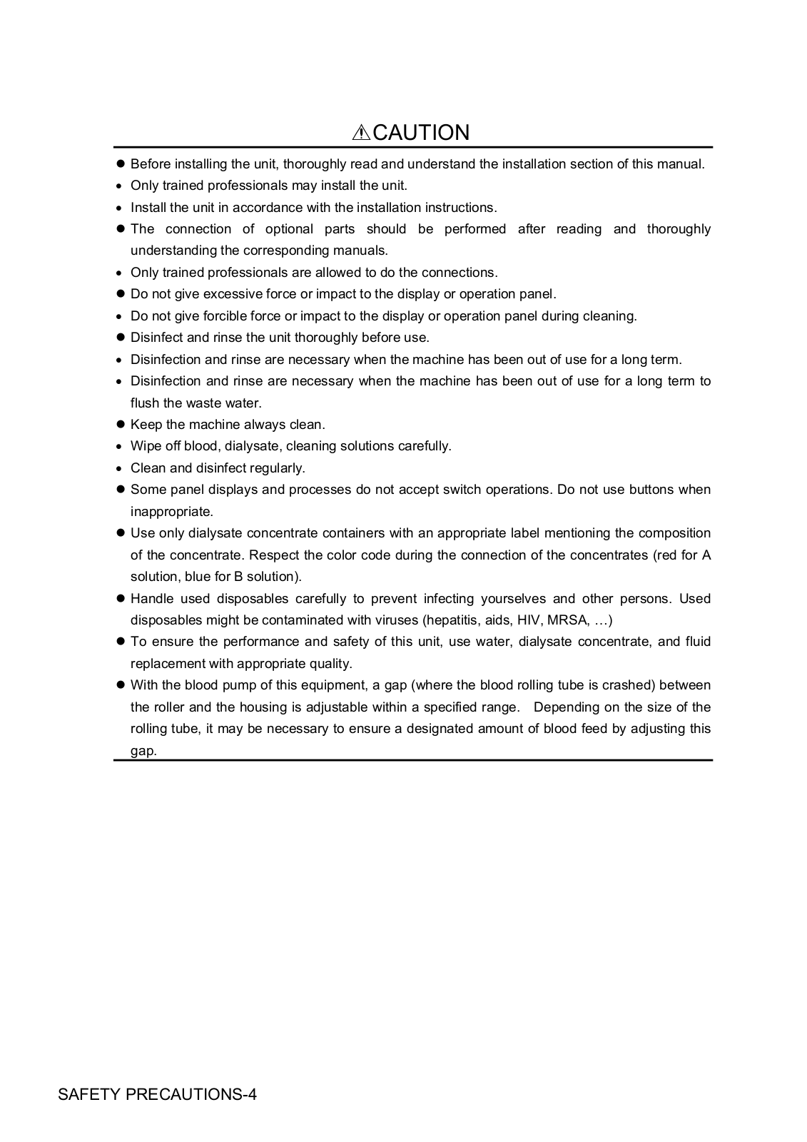
CAUTION

zBefore installing the unit, thoroughly read and understand the installation section of this manual.

• Only trained professionals may install the unit.

• Install the unit in accordance with the installation instructions.

zThe connection of optional parts should be performed after reading and thoroughly understanding the corresponding manuals.

• Only trained professionals are allowed to do the connections.

z Do not give excessive force or impact to the display or operation panel.

• Do not give forcible force or impact to the display or operation panel during cleaning. z Disinfect and rinse the unit thoroughly before use.

• Disinfection and rinse are necessary when the machine has been out of use for a long term.

• Disinfection and rinse are necessary when the machine has been out of use for a long term to flush the waste water.

z Keep the machine always clean.

• Wipe off blood, dialysate, cleaning solutions carefully.

• Clean and disinfect regularly.

z Some panel displays and processes do not accept switch operations. Do not use buttons when inappropriate.

z Use only dialysate concentrate containers with an appropriate label mentioning the composition of the concentrate. Respect the color code during the connection of the concentrates (red for A solution, blue for B solution).

z Handle used disposables carefully to prevent infecting yourselves and other persons. Used disposables might be contaminated with viruses (hepatitis, aids, HIV, MRSA, …)

z To ensure the performance and safety of this unit, use water, dialysate concentrate, and fluid replacement with appropriate quality.

zWith the blood pump of this equipment, a gap (where the blood rolling tube is crashed) between the roller and the housing is adjustable within a specified range. Depending on the size of the rolling tube, it may be necessary to ensure a designated amount of blood feed by adjusting this gap.

SAFETY PRECAUTIONS-4

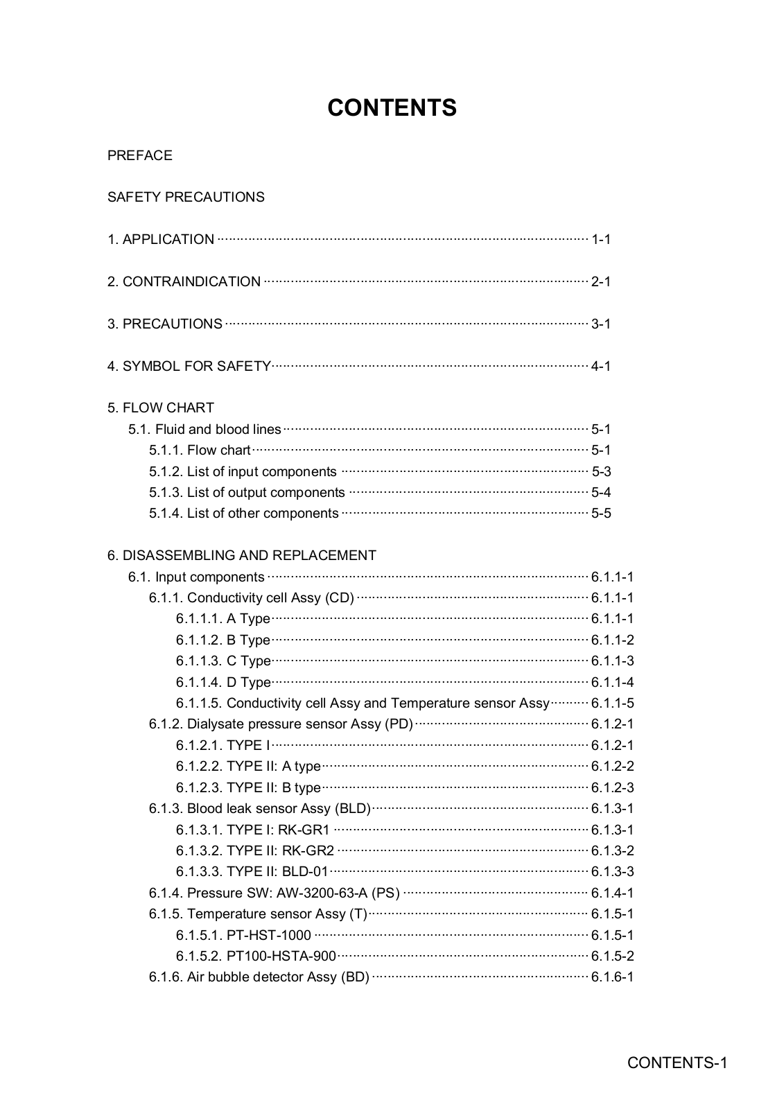
CONTENTS

PREFACE

SAFETY PRECAUTIONS

1.APPLICATION ································································································ 1-1

2.CONTRAINDICATION ···················································································· 2-1

3.PRECAUTIONS ······························································································ 3-1

4.SYMBOL FOR SAFETY·················································································· 4-1

5.FLOW CHART

5.1.Fluid and blood lines··············································································· 5-1

5.1.1.Flow chart······················································································· 5-1

5.1.2.List of input components ································································ 5-3

5.1.3.List of output components ······························································ 5-4

5.1.4.List of other components ································································ 5-5

6.DISASSEMBLING AND REPLACEMENT

6.1.Input components ··················································································· 6.1.1-1

6.1.1.Conductivity cell Assy (CD) ···························································· 6.1.1-1

6.1.1.1.A Type·················································································· 6.1.1-1

6.1.1.2.B Type·················································································· 6.1.1-2

6.1.1.3.C Type·················································································· 6.1.1-3

6.1.1.4.D Type·················································································· 6.1.1-4

6.1.1.5.Conductivity cell Assy and Temperature sensor Assy·········· 6.1.1-5

6.1.2.Dialysate pressure sensor Assy (PD)············································· 6.1.2-1

6.1.2.1.TYPE I·················································································· 6.1.2-1

6.1.2.2.TYPE II: A type····································································· 6.1.2-2

6.1.2.3.TYPE II: B type····································································· 6.1.2-3

6.1.3.Blood leak sensor Assy (BLD)························································ 6.1.3-1

6.1.3.1.TYPE I: RK-GR1 ·································································· 6.1.3-1

6.1.3.2.TYPE II: RK-GR2 ································································· 6.1.3-2

6.1.3.3.TYPE II: BLD-01··································································· 6.1.3-3

6.1.4.Pressure SW: AW-3200-63-A (PS) ················································ 6.1.4-1

6.1.5.Temperature sensor Assy (T)························································· 6.1.5-1

6.1.5.1.PT-HST-1000 ······································································· 6.1.5-1

6.1.5.2.PT100-HSTA-900································································· 6.1.5-2

6.1.6.Air bubble detector Assy (BD) ························································ 6.1.6-1

CONTENTS-1

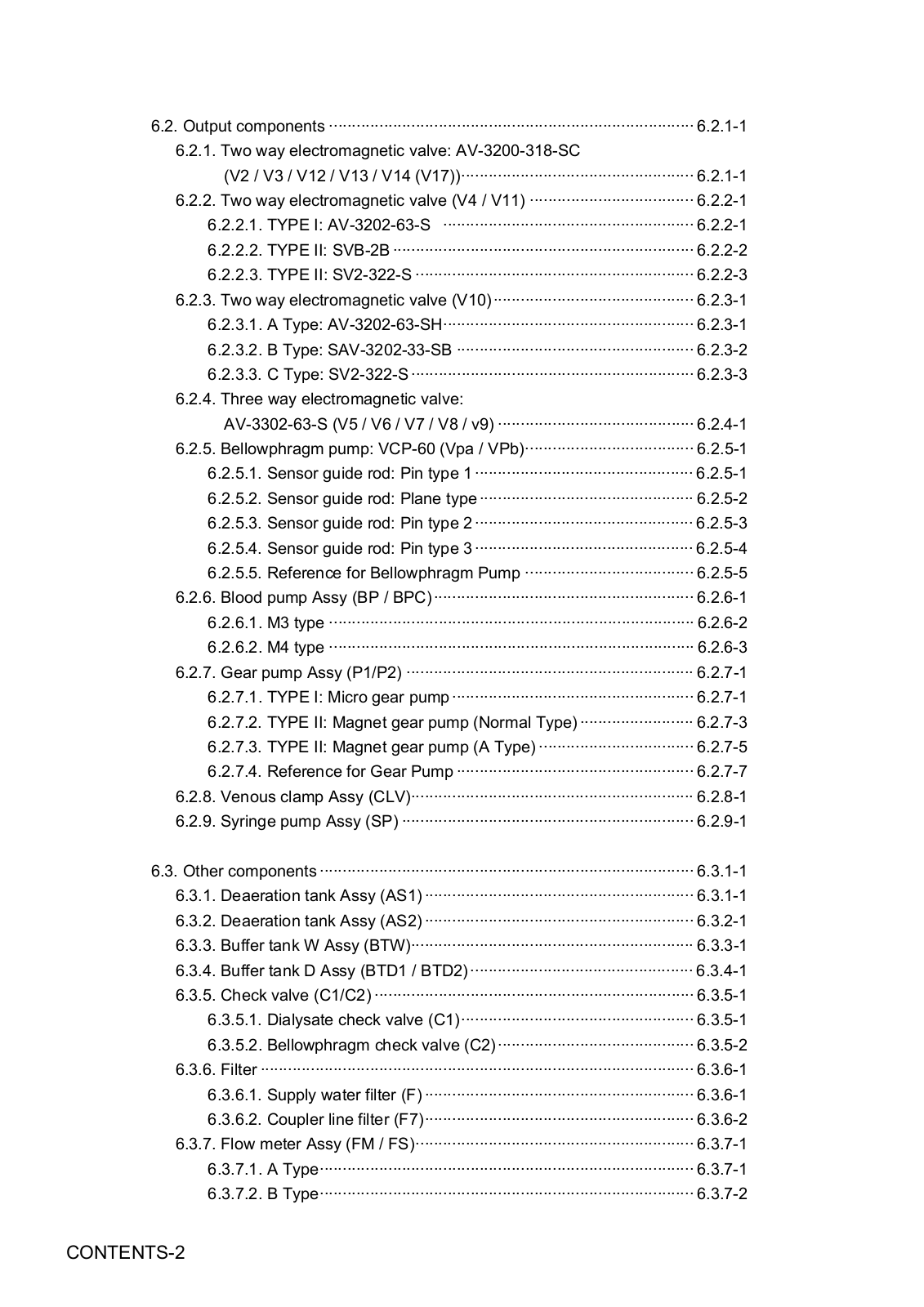
6.2.Output components ················································································ 6.2.1-1

6.2.1.Two way electromagnetic valve: AV-3200-318-SC

(V2 / V3 / V12 / V13 / V14 (V17))··················································· 6.2.1-1

6.2.2.Two way electromagnetic valve (V4 / V11) ···································· 6.2.2-1

6.2.2.1.TYPE I: AV-3202-63-S ······················································· 6.2.2-1

6.2.2.2.TYPE II: SVB-2B ·································································· 6.2.2-2

6.2.2.3.TYPE II: SV2-322-S ····························································· 6.2.2-3

6.2.3.Two way electromagnetic valve (V10)············································ 6.2.3-1

6.2.3.1.A Type: AV-3202-63-SH······················································· 6.2.3-1

6.2.3.2.B Type: SAV-3202-33-SB ···················································· 6.2.3-2

6.2.3.3.C Type: SV2-322-S ······························································ 6.2.3-3

6.2.4.Three way electromagnetic valve:

AV-3302-63-S (V5 / V6 / V7 / V8 / v9) ··········································· 6.2.4-1

6.2.5.Bellowphragm pump: VCP-60 (Vpa / VPb)····································· 6.2.5-1

6.2.5.1.Sensor guide rod: Pin type 1 ················································ 6.2.5-1

6.2.5.2.Sensor guide rod: Plane type ··············································· 6.2.5-2

6.2.5.3.Sensor guide rod: Pin type 2 ················································ 6.2.5-3

6.2.5.4.Sensor guide rod: Pin type 3 ················································ 6.2.5-4

6.2.5.5.Reference for Bellowphragm Pump ····································· 6.2.5-5

6.2.6.Blood pump Assy (BP / BPC)························································· 6.2.6-1

6.2.6.1.M3 type ················································································ 6.2.6-2

6.2.6.2.M4 type ················································································ 6.2.6-3

6.2.7.Gear pump Assy (P1/P2) ······························································· 6.2.7-1

6.2.7.1.TYPE I: Micro gear pump····················································· 6.2.7-1

6.2.7.2.TYPE II: Magnet gear pump (Normal Type) ························· 6.2.7-3

6.2.7.3.TYPE II: Magnet gear pump (A Type) ·································· 6.2.7-5

6.2.7.4.Reference for Gear Pump ···················································· 6.2.7-7

6.2.8.Venous clamp Assy (CLV)······························································ 6.2.8-1

6.2.9.Syringe pump Assy (SP) ································································ 6.2.9-1

6.3.Other components ·················································································· 6.3.1-1

6.3.1.Deaeration tank Assy (AS1) ··························································· 6.3.1-1

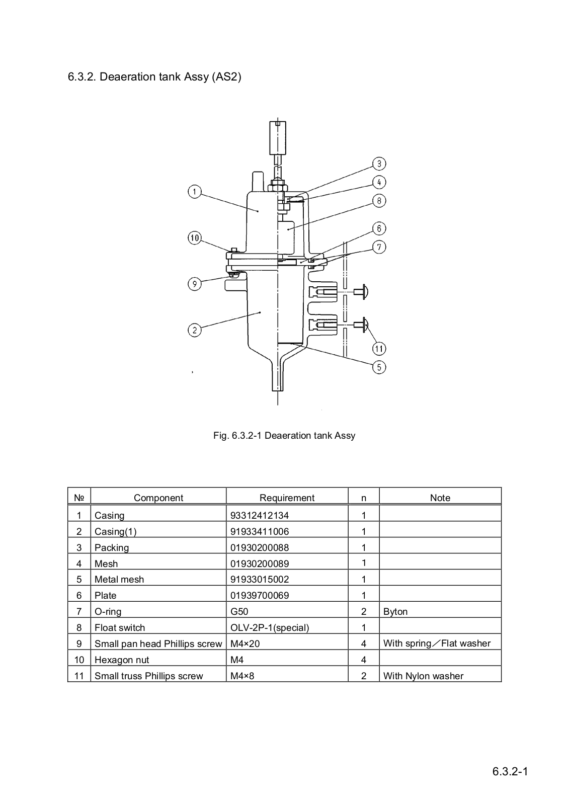
6.3.2.Deaeration tank Assy (AS2) ··························································· 6.3.2-1

6.3.3.Buffer tank W Assy (BTW)······························································ 6.3.3-1

6.3.4.Buffer tank D Assy (BTD1 / BTD2) ················································· 6.3.4-1

6.3.5.Check valve (C1/C2) ······································································ 6.3.5-1

6.3.5.1.Dialysate check valve (C1)··················································· 6.3.5-1

6.3.5.2.Bellowphragm check valve (C2)··········································· 6.3.5-2

6.3.6.Filter ······························································································· 6.3.6-1

6.3.6.1.Supply water filter (F) ··························································· 6.3.6-1

6.3.6.2.Coupler line filter (F7)··························································· 6.3.6-2

6.3.7.Flow meter Assy (FM / FS)····························································· 6.3.7-1

6.3.7.1.A Type·················································································· 6.3.7-1

6.3.7.2.B Type·················································································· 6.3.7-2

CONTENTS-2

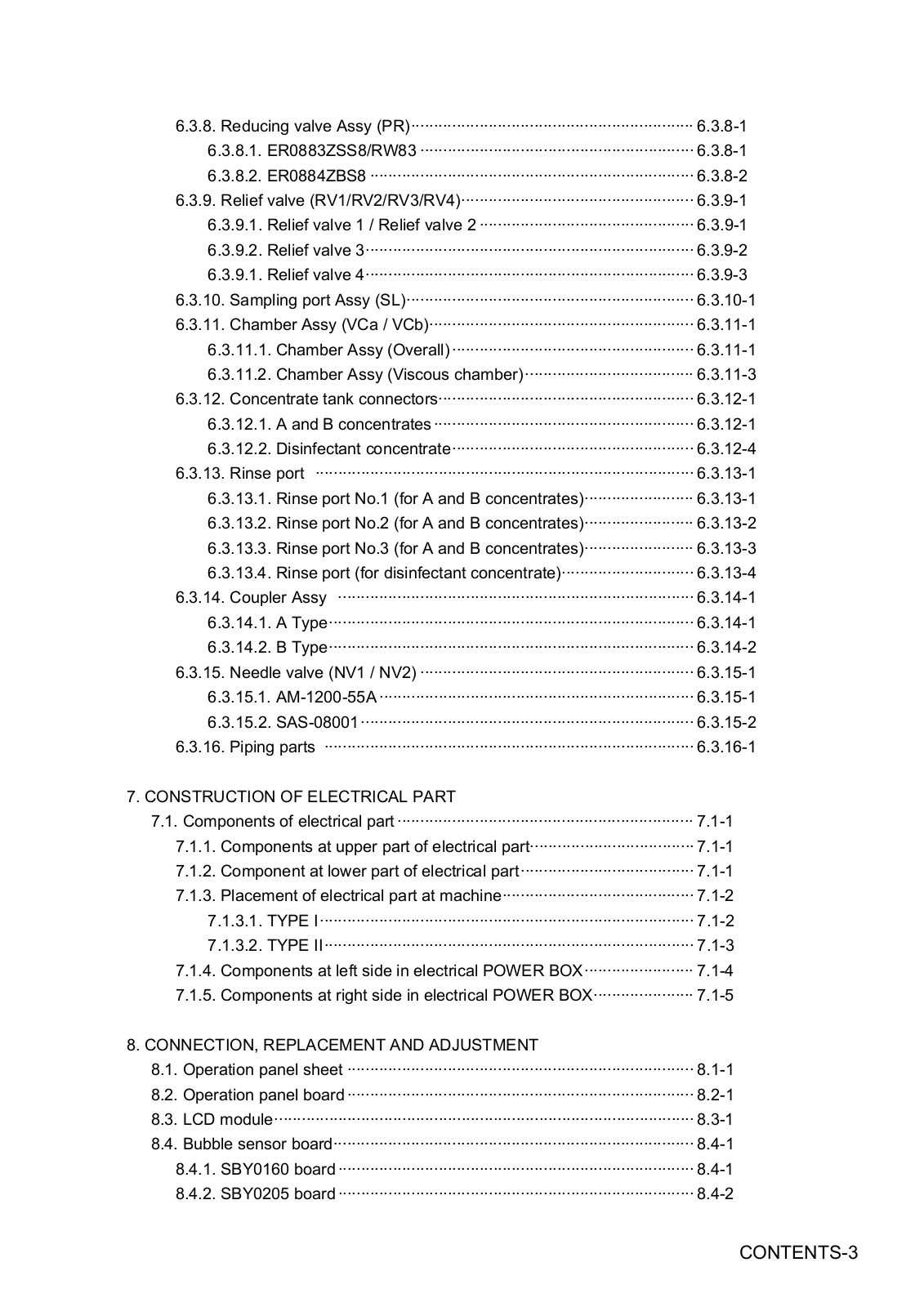
6.3.8.Reducing valve Assy (PR)······························································ 6.3.8-1

6.3.8.1.ER0883ZSS8/RW83 ···························································· 6.3.8-1

6.3.8.2.ER0884ZBS8 ······································································· 6.3.8-2

6.3.9.Relief valve (RV1/RV2/RV3/RV4)··················································· 6.3.9-1

6.3.9.1.Relief valve 1 / Relief valve 2 ··············································· 6.3.9-1

6.3.9.2.Relief valve 3········································································ 6.3.9-2

6.3.9.1.Relief valve 4········································································ 6.3.9-3

6.3.10.Sampling port Assy (SL)······························································· 6.3.10-1

6.3.11.Chamber Assy (VCa / VCb)·························································· 6.3.11-1

6.3.11.1.Chamber Assy (Overall)····················································· 6.3.11-1

6.3.11.2.Chamber Assy (Viscous chamber)····································· 6.3.11-3

6.3.12.Concentrate tank connectors························································ 6.3.12-1

6.3.12.1.A and B concentrates························································· 6.3.12-1

6.3.12.2.Disinfectant concentrate····················································· 6.3.12-4

6.3.13.Rinse port ··················································································· 6.3.13-1

6.3.13.1.Rinse port No.1 (for A and B concentrates)························ 6.3.13-1

6.3.13.2.Rinse port No.2 (for A and B concentrates)························ 6.3.13-2

6.3.13.3.Rinse port No.3 (for A and B concentrates)························ 6.3.13-3

6.3.13.4.Rinse port (for disinfectant concentrate)····························· 6.3.13-4

6.3.14. Coupler Assy ·············································································· 6.3.14-1

6.3.14.1.A Type················································································ 6.3.14-1

6.3.14.2.B Type················································································ 6.3.14-2

6.3.15.Needle valve (NV1 / NV2) ···························································· 6.3.15-1

6.3.15.1.AM-1200-55A ····································································· 6.3.15-1

6.3.15.2.SAS-08001········································································· 6.3.15-2

6.3.16.Piping parts ················································································· 6.3.16-1

7.CONSTRUCTION OF ELECTRICAL PART

7.1.Components of electrical part ································································· 7.1-1

7.1.1.Components at upper part of electrical part···································· 7.1-1

7.1.2.Component at lower part of electrical part······································ 7.1-1

7.1.3.Placement of electrical part at machine·········································· 7.1-2 7.1.3.1. TYPE I·················································································· 7.1-2 7.1.3.2. TYPE II················································································· 7.1-3

7.1.4.Components at left side in electrical POWER BOX························ 7.1-4

7.1.5.Components at right side in electrical POWER BOX······················ 7.1-5

8.CONNECTION, REPLACEMENT AND ADJUSTMENT

8.1.Operation panel sheet ············································································ 8.1-1

8.2.Operation panel board············································································ 8.2-1

8.3.LCD module···························································································· 8.3-1

8.4.Bubble sensor board··············································································· 8.4-1

8.4.1.SBY0160 board·············································································· 8.4-1

8.4.2.SBY0205 board·············································································· 8.4-2

CONTENTS-3

8.5.Dialysate pressure sensor board ···························································· 8.5-1

8.5.1.TYPE I···························································································· 8.5-1

8.5.2.TYPE II: A Type·············································································· 8.5-3

8.5.3.TYPE II: B Type·············································································· 8.5-4

8.6.Main board······························································································ 8.6-1

8.7.Venous and arterial pressure sensor boards ·········································· 8.7-1

8.8.DSUB board ··························································································· 8.8-1

8.9.Buzzer board: SBY0162 board / SBY0267 board··································· 8.9-1

8.10.Sub-board····························································································· 8.10-1

8.10.1.SBY0157 board / SBY0163 board················································ 8.10-1

8.10.2.SBY0270 board ············································································ 8.10-5

8.11.DC+5V, ±12V Power supply ································································· 8.11-1

8.11.1.Switching regulator: SWT30-522 / SWT30-522kai ······················· 8.11-1

8.11.2.Switching regulator: LDC30F-1-G / LDC30F-1-Gkai ···················· 8.11-3

8.11.3.DC+5V, ±12V converter board: SBY0254 ···································· 8.11-5

8.12.DC+24V switching regulator ································································· 8.12-1

8.12.1.PLEY24HSZ-C ············································································· 8.12-1

8.12.2.ZWS150PAF-24/J ········································································ 8.12-4

8.12.3.CME150-24 ·················································································· 8.12-6

8.13.Operation panel board, main board, sub-board ···································· 8.13-1

8.14.VR board: SBY0268 board ··································································· 8.14-1

8.15.FUSE···································································································· 8.15-1

9.MAINTENANCE MODES

9.1.Display···································································································· 9.1-1

9.2.Maintenance modes ··············································································· 9.2-1

9.2.1.ROM before Ver.2.40 ····································································· 9.2-1

9.2.2.ROM after Ver.3.00 ········································································ 9.2-3

9.3.Maintenance mode menu screen···························································· 9.3-1

9.4.Maintenance mode 1 screen ·································································· 9.4-1

9.4.1.ROM before Ver.2.40 ····································································· 9.4-1

9.4.2.ROM after Ver.3.00 ········································································ 9.4-2

9.5.Maintenance mode 2 screen ·································································· 9.5-1

9.6.Maintenance mode 3 screen ·································································· 9.6-1

9.7.Maintenance mode 4 screen ·································································· 9.7-1

9.8.Maintenance mode 5 screen ·································································· 9.8-1

9.8.1.When dialysis mode BC1 or BC2 is set·········································· 9.8-1

9.8.2.When dialysis mode AC is set························································ 9.8-2

9.9.Maintenance mode 6 screen ·································································· 9.9-1

9.9.1.ROM before Ver.3.70 ····································································· 9.9-2

9.9.2.ROM after Ver.3.84 ········································································ 9.9-4

9.10.Maintenance mode 7 screen ································································ 9.10-1

9.10.1.ROM before Ver.2.40 ··································································· 9.10-2

9.10.2.ROM after Ver.3.00 ······································································ 9.10-3

CONTENTS-4

9.11.Maintenance mode 8 screen ································································ 9.11-1

9.11.1.ROM before Ver.2.40 ··································································· 9.11-2

9.11.2.ROM after Ver.3.00 ······································································ 9.11-3

9.11.2.1.Monitor screen ······································································· 9.11-3

9.11.2.2.Input screen··········································································· 9.11-3

9.11.2.3.Zero cleared screen······························································· 9.11-3

9.12.Maintenance mode 9 screen ································································ 9.12-1

9.13.Maintenance mode 10 screen ······························································ 9.13-1

10.ADJUSTMENT

10.1.Measurement of chamber capacity

and adjustment of silicone volume······································ 10.1-1

10.1.1.Measurement of chamber capacity ·············································· 10.1-1

10.1.2.Adjustment of silicone oil volume ················································· 10.1-3

10.2.Adjustment of venous and arterial pressure sensors···························· 10.2-1

10.2.1.Adjustment of venous pressure sensor ········································ 10.2-1

10.2.2.Adjustment of arterial pressure sensor········································· 10.2-2

10.3.Adjustment dialysate pressure sensor ·················································· 10.3-1

10.3.1.TYPE I·························································································· 10.3-1

10.3.2.TYPE II························································································· 10.3-3

10.3.2.1.Adjustment dialysate pressure sensor ··································· 10.3-3

10.3.2.2.Adjustment of PD offset ························································· 10.3-5

10.4.Adjustment of temperature sensor························································ 10.4-1

10.5.Adjustment of pressure SW ·································································· 10.5-1

10.6.Adjustment of blood leak sensor··························································· 10.6-1

10.6.1.TYPE I: RK-GR1 ·········································································· 10.6-1

10.6.2.TYPE II: RK-GR2 ········································································· 10.6-3

10.6.2.1.Zero revision of blood leak detector······································· 10.6-3

10.6.2.2.Check of accuracy of blood leak sensor using pseudo filter ·· 10.6-4

10.6.3.TYPE II: BLD-01··········································································· 10.6-5

10.6.3.1.Zero offset of blood leak sensor············································· 10.6-5

10.6.3.2.Checking through pseudo blood leak filter····························· 10.6-6

10.6.3.3.Adjustment of blood leak sensor············································ 10.6-7

10.7.Adjustment of reducing valve································································ 10.7-1

10.8.Adjustment of priming end pressure ····················································· 10.8-1

10.9.Adjustment of closed circuit pressure ··················································· 10.9-1

10.10.Adjustment of priming flow rate··························································· 10.10-1

10.10.1.Adjustment by Flow meter·························································· 10.10-1

10.10.2.Adjustment by Discharge Flow Time ·········································· 10.10-2

10.11.Adjustment of bypass flow rate··························································· 10.11-1

10.12.Adjustment of gaps between housing

and rotor rollers of blood pump······································ 10.12-1

10.12.1.Adjustment by water head pressure ··········································· 10.12-1

10.12.2.Adjustment using syringe and manometer ································· 10.12-2

CONTENTS-5

10.13.Adjustment of blood pump flow rate···················································· 10.13-1

10.13.1.In case of you use Standard Rolling Tube (φ8×φ12mm)············ 10.13-1

10.13.2.In case of you use Small Rolling Tube (φ6.35×φ9.75mm) ········· 10.13-2

10.14.Leak test and gap adjustment of clamp ·············································· 10.14-1

10.14.1.Leak test of clamp ······································································ 10.14-1

10.14.2.Gap adjustment of clamp···························································· 10.14-2

10.15.Adjustment of bubble sensor ······························································ 10.15-1

10.15.1. SBY0160 board ········································································ 10.15-1

10.15.2.SBY0205 board ·········································································· 10.15-2

10.16.Adjustment of conductivity and concentration····································· 10.16-1

10.16.1.Selection of dialysis mode to be adjusted··································· 10.16-2

10.16.2.Input of concentration data························································· 10.16-3

10.16.3.Adjustment of dilution ratio ························································· 10.16-5

10.16.4.Calibration of indicated conductivity and concentration·············· 10.16-8

10.17.Adjustment of contrast ········································································ 10.17-1

10.18.Adjustment of gas purge pressure······················································ 10.18-1

10.19.Adjustment of flashing volume in concentrate line······························ 10.19-1

10.19.1.Confirmation of flushing volume ················································· 10.19-1

10.19.2.Adjustment of flushing volume···················································· 10.19-2

10.20.Adjustment of priming volume in concentrate line······························· 10.20-1

10.20.1.Confirmation of priming volume·················································· 10.20-1

10.20.2.Adjustment of priming volume ···················································· 10.20-2

10.21.Adjustment of syringe pump infusion flow··········································· 10.21-1

10.22.Adjustment of overload detection on Syringe pump Assy,

when other than Nipro syringe used ··················································· 10.22-1

10.23.Adjustment of conductivity sensor ······················································ 10.23-1

11.DIP SWITCHES

11.1Operation of dip SW’s············································································ 11.1-1

11.2.Functions of dip SW’s··········································································· 11.2-1 11.2.1. ROM before Ver.2.40 ··································································· 11.2-1 11.2.2. ROM after Ver.3.00 ······································································ 11.2-2 11.2.3. ROM after Ver.3.93 ······································································ 11.2-3

12.VARIOUS DATA

12.1.Loaded CPU and ROM········································································· 12.1-1

12.2.Wiring in POWER box ·········································································· 12.2-1 12.2.1. Electrical power box ····································································· 12.2-1 12.2.2. A Type·························································································· 12.2-3 12.2.3. B Type·························································································· 12.2-4 12.2.4. C Type·························································································· 12.2-5 12.2.5. D Type·························································································· 12.2-6

12.3.Record sheet of setting value ······························································· 12.3-1 12.3.1. ROM before Ver.2.40 ··································································· 12.3-2

CONTENTS-6

12.3.2.ROM after Ver.3.00 ······································································ 12.3-4

12.3.3.ROM after Ver.3.84 ······································································ 12.3-6

CONTENTS-7

CONTENTS-8

1.APPLICATION

(a)Single patient dialysis machine, SURDIAL is applied to treatment of patients with acute or chronic renal failure by dialysis when the application is instructed by doctor.

(b)SURDIAL can be used at both hospital and home.

1-1

1-2

2. CONTRAINDICATION

Any application other than dialysis using SURDIAL is contraindicated.

2-1

2-2

3. PRECAUTIONS

The following precautions should be noted when using this unit:

1.This unit should be operated by skilled personnel only.

2.Important notes concerning the installation of the machine:

(1)Keep the unit out of water.

(2)Only use the machine in normal conditions. Normal air pressure, temperature, humidity, wind, sunlight. No air containing dust, salt, sulfur…

(3)Stability in terms of tilt, vibration, or impact (including those during delivery) should be taken care of.

(4)Do not install the unit where chemicals are stored or gasses are generated.

(5)Take care about the frequency, voltage, and allowed current /power consumption of the power source.

(6)Connect the earth protection properly.

3.Important notes concerning the use of the machine:

(1)Inspect touch panel sensitivity, polarity, dial settings, and meters. Verify that the machine operates properly.

(2)Ensure that the earth protection is fully connected.

(3)Verify that all cable connections are intact.

(4)Exercise caution for concomitant use of equipment, since it can result in false diagnosis or danger.

(5)Re-examine the external circuit that will be connected directly to the patient.

4.Important notes concerning the operation of the machine:

(1)Monitor the unit and patient for any abnormality at all times.

(2)When an abnormality is discovered in the unit or patient, act appropriately (e.g., stop the operation after confirming the safety of the patient).

(3)Do not allow the patient to touch the unit.

5.Important notes concerning the end of the treatment:

(1)Turn the power off after returning operation buttons, dials, etc., to the original positions by the indicated processes.

(2)When removing cables, do not apply inappropriate force such as pulling them by holding the cables.

(3)Take care about the storage conditions:

1)Keep the unit out of water.

2)Store the unit in normal conditions. Normal air pressure, temperature, humidity, wind, sunlight. No air containing dust, salt, sulfur…

3)Stability in terms of tilt, vibration, or impact (including those during delivery) should be taken care of.

4)Do not store the unit where chemicals are stored or gasses are generated.

(4)Clean accessories, cables, electrodes, etc., and keep them in an organized way.

(5)Ensure to keep the unit clean to be ready for the next use.

6.When the unit fails, do not attempt to fix it. Note the failure description on the machine and look for professional help.

7.Do not modify the unit.

8.Maintenance (See Maintenance Manual.)

(1)Ensure to maintain the unit and its parts.

(2)Ensure that the machine operates normally and safely after a long period out of use.

9.Check other handling precautions listed on the instruction manual of the unit.

3-1

3-2

4.SYMBOL FOR SAFETY

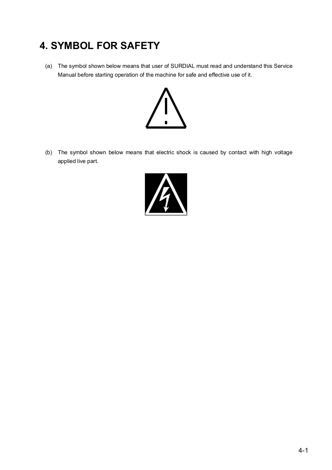
(a)The symbol shown below means that user of SURDIAL must read and understand this Service Manual before starting operation of the machine for safe and effective use of it.

(b)The symbol shown below means that electric shock is caused by contact with high voltage applied live part.

4-1

4-2

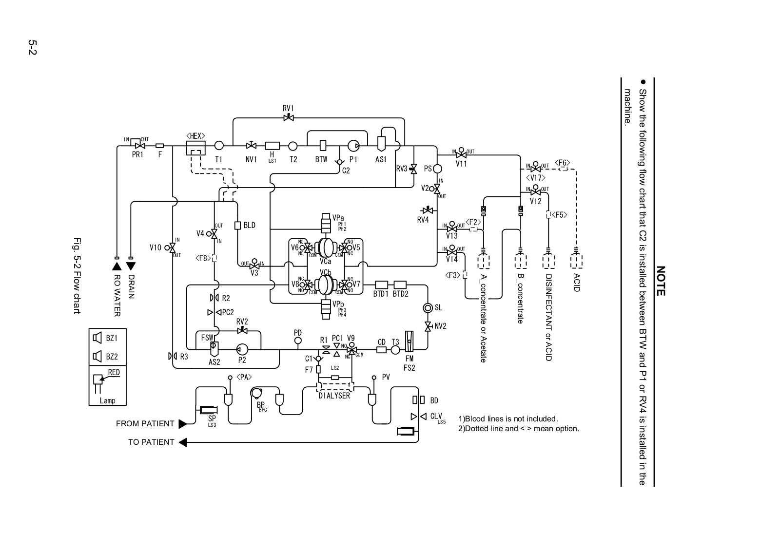
5. FLOW CHART

RV1


IN

OUT


<HEX>


PR1

F


T1

NV1

H

T2

BTW

P1


LS1


C2


BLD


VPa


OUT


PH1


V4


PH2


Fig


IN


IN


NO


NO


.


V10


V6


V5

-5


OUT

<F8>


NC

COM

COM

NC


OUT

IN


VCa


1


chartFlow

WATERRO

DRAIN


PC2

V3


V8NC


VCb

NCV7


PH4


R2


NO

COM

COM

NO


VPb


PH3


RV2


BZ1


FSW


PD

PC1 V9


R1


NO

BZ2

R3

AS2

P2

C1

NC COM


LS2

RED


F7


<PA>


AS1

RV3

BTD1 BTD2

CD T3

FM

FS2

PV

IN OUT

PS

V11


IN


V2


OUT


IN OUT<F2>


V13


IN OUT


V14


<F3>

concentrateA


SL


NV2

Acetate or


IN OUT <F6>

<V17>

IN OUT

V12

<F5>


concentrate B

DISINFECTANT

ACID


ACID or


Lamp


DIALYSER

BD


BP


BPC


FROM PATIENT

SP


CLV

1)Blood lines is not included.


LS5

LS3


2)Dotted line and < > mean option.


TO PATIENT

1-5


lines blood and Fluid .1.5 chart Flow .1.1.5

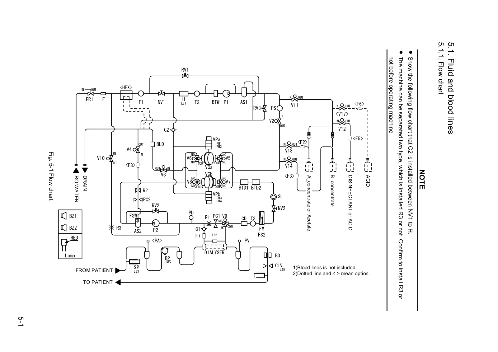
NV1 between installed is C2 that chart flow following the Show R3 installed is which type, two separated be can machine The machine operating before not

NOTE

not or

.H to


or R3 install to Confirm .


Nipro Surdial Service manual (1004)

2-5


RV1


IN

OUT


<HEX>


PR1

F


H


IN

OUT


T1

NV1

T2

BTW


P1

AS1


LS1


V11

IN

OUT

<F6>


C2


RV3

PS


<V17>


IN


V2


IN

OUT


OUT


V12


VPa


RV4


OUT<F2>


<F5>


BLD


OUT


PH1


IN


V4


PH2


Fig


IN


V13


V10


IN


V6NO


NOV5


.


NC


NC


IN

OUT


-5


OUT


<F8>


COM

VCa

COM


V14


OUT

IN


2


chartFlow


DRAIN


V3


VCb


<F3>

concentrateB

ACIDorDISINFECTANT

ACID

RO


AS2

P2


NC

C1


NC


FM


AcetateorconcentrateA


WATER


PC2


V8


PH4

V7


NO


NO


BTD1 BTD2


R2


COM


COM


VPb


SL


PH3


RV2


NV2


PD


BZ1


FSW


R1 PC1 V9


CD

T3


NO


BZ2


R3


F7


NC

COM


FS2


RED


LS2


<PA>


PV


Lamp


DIALYSER

BD


BP


BPC


CLV


FROM PATIENT

SP


1)Blood lines is not included.


LS5

LS3


2)Dotted line and < > mean option.


TO PATIENT

the Show .machine


between installed is C2 that chart flow following

NOTE

the in installed is RV4 or P1 and BTW


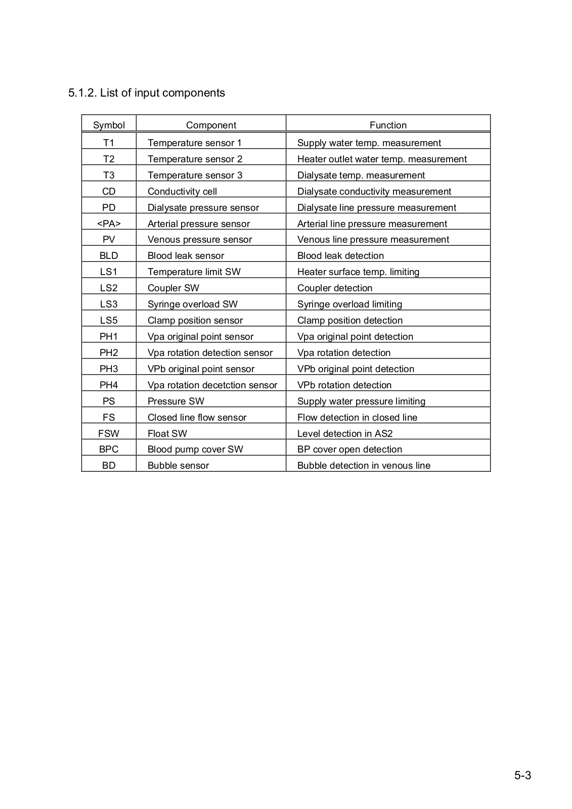
5.1.2. List of input components

Symbol

Component

Function


T1

Temperature sensor 1

Supply water temp. measurement

T2

Temperature sensor 2

Heater outlet water temp. measurement

T3

Temperature sensor 3

Dialysate temp. measurement

CD

Conductivity cell

Dialysate conductivity measurement

PD

Dialysate pressure sensor

Dialysate line pressure measurement

<PA>

Arterial pressure sensor

Arterial line pressure measurement

PV

Venous pressure sensor

Venous line pressure measurement

BLD

Blood leak sensor

Blood leak detection

LS1

Temperature limit SW

Heater surface temp. limiting

LS2

Coupler SW

Coupler detection

LS3

Syringe overload SW

Syringe overload limiting

LS5

Clamp position sensor

Clamp position detection

PH1

Vpa original point sensor

Vpa original point detection

PH2

Vpa rotation detection sensor

Vpa rotation detection

PH3

VPb original point sensor

VPb original point detection

PH4

Vpa rotation decetction sensor

VPb rotation detection

PS

Pressure SW

Supply water pressure limiting

FS

Closed line flow sensor

Flow detection in closed line

FSW

Float SW

Level detection in AS2

BPC

Blood pump cover SW

BP cover open detection

BD

Bubble sensor

Bubble detection in venous line

5-3

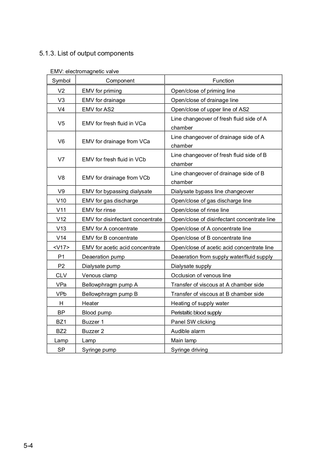
5.1.3. List of output components

EMV: electromagnetic valve

Symbol

Component

Function


V2

EMV for priming

Open/close of priming line

V3

EMV for drainage

Open/close of drainage line

V4

EMV for AS2

Open/close of upper line of AS2

V5

EMV for fresh fluid in VCa

Line changeover of fresh fluid side of A

chamber


V6

EMV for drainage from VCa

Line changeover of drainage side of A

chamber


V7

EMV for fresh fluid in VCb

Line changeover of fresh fluid side of B

chamber


V8

EMV for drainage from VCb

Line changeover of drainage side of B

chamber


V9

EMV for bypassing dialysate

Dialysate bypass line changeover

V10

EMV for gas discharge

Open/close of gas discharge line

V11

EMV for rinse

Open/close of rinse line

V12

EMV for disinfectant concentrate

Open/close of disinfectant concentrate line

V13

EMV for A concentrate

Open/close of A concentrate line

V14

EMV for B concentrate

Open/close of B concentrate line

<V17>

EMV for acetic acid concentrate

Open/close of acetic acid concentrate line

P1

Deaeration pump

Deaeration from supply water/fluid supply

P2

Dialysate pump

Dialysate supply

CLV

Venous clamp

Occlusion of venous line

VPa

Bellowphragm pump A

Transfer of viscous at A chamber side

VPb

Bellowphragm pump B

Transfer of viscous at B chamber side

H

Heater

Heating of supply water

BP

Blood pump

Peristaltic blood supply

BZ1

Buzzer 1

Panel SW clicking

BZ2

Buzzer 2

Audible alarm

Lamp

Lamp

Main lamp

SP

Syringe pump

Syringe driving

5-4

Loading...
+ 296 hidden pages