

Page 1
Mega Kitchen System
OWNER’S GUIDE
BL770NZ
®
®
HELP LINE
AUST: 1800 890 840
NZ: 0800 002 999
Page 2

1 2
AUST: 1800 89 0 840 NZ: 080 0 002 999
19. DO NOT expose containers to extreme
temperature changes.
20. CAUTION: DO NOT BLEND HOT LIQUIDS.
21. DO NOT over fill.
22. Extreme caution must be used when
moving an appliance containing hot
food, water or other liquids.
23. DO NOT operate the appliance empty.
24. To reduce the risk of burns, always allow
the appliance to cool before taking off
parts and before cleaning.
25. Max ON time is 30 seconds under
1500W load. If the appliance overheats,
a thermal switch will become activated
and shut off the motor. To reset, unplug
the appliance and let it cool down for
approximately 15 minutes before using
again.
26. In the event that the unit overloads, the
control panel lights will flash and the
unit will shut down. Unplug the unit and
wait 15 minutes to reset.
27. THIS PRODUCT IS INTENDED FOR
HOUSEHOLD USE ONLY. Do not use this
appliance for anything other than its
intended use. Do not use outdoors.
28. The maximum rating is based on
the 6-Blade Assembly (pitcher) that
drives the greatest power and other
recommended attachments may draw
significantly less power or current.
WARNING: Extension cords are
not recommended for use with this
product.
IMPORTANT SAFETY INSTRUCTIONS
For Household Use Only
WHEN USING ELECTRICAL APPLIANCES,
BASIC SAFETY PRECAUTIONS SHOULD
ALWAYS BE FOLLOWED, INCLUDING THE
FOLLOWING:
READ ALL INSTRUCTIONS BEFORE USING
YOUR NINJA® PROFESSIONAL BLENDER.
IMPO RTANT:
This appliance can be used
by children aged from 8 years and above
and persons with reduced physical, sensory
or mental capabilities or lack of experience
and knowledge if they have been given
supervision or instruction concerning use of
the appliance in a safe way and understand
the hazards involved. Children should be
supervised to ensure that they do not play
with the appliance. Cleaning and user
maintenance shall not be made by children
without supervision.
CAUTION: ln order to avoid a hazard due to
inadvertent resetting of the thermal cut-out,
this appliance must not be supplied through
an external switching device, such as a timer,
or connected to a circuit that is regularly
switched on and off by the utility.
8. Always use appliance on a dry, level
surface.
9. Keep hands, hair, clothing, as well as
utensils out of container while blending
to reduce the risk of severe injury to
persons or damage to the appliance. A
scraper may be used but only when the
appliance is not running.
10. CAUTION: Blade assembly is sharp,
handle with care. When handling the
blade assembly, always hold by the shaft.
11. Avoid contact with moving parts.
12. DO NOT attempt to sharpen blades.
13. DO NOT use the appliance if blade
assembly is bent or damaged.
14. To reduce risk of injury, never place the
blade assembly on base without pitcher
or bowl properly attached.
15. DO NOT operate this appliance on or
near any hot surfaces (such as gas or
electric burner or in a heated oven).
16. The use of attachments or accessories
including canning jars, not
recommended by the manufacturer may
result in fire, electric shock or personal
inj ur y.
17. DO NOT remove the container from the
motor base while the appliance is in
operation.
18. To reduce the risk of injury, NEVER
operate the appliance without the
lid in place; DO NOT try to defeat the
interlock mechanism; make sure that the
attachment is properly installed before
operating the appliance.
WARNING:
TO REDUC E THE RISK OF FIRE , ELEC TRIC
SHOCK OR I NJURY:
1. To protect against electrical shock, do
not submerge the appliance or allow the
power cord to come into contact with
water or any other liquid.
2. DO NOT allow young children to operate
the appliance or use as a toy. Close
supervision is necessary when any
appliance is used by or near children.
3. Never leave an appliance unattended
when in use.
4. Turn the appliance Off and remove the
power cord from the electrical outlet
when not in use, before assembling or
disassembling parts and before cleaning.
To unplug, grasp the plug and pull from
the electrical outlet. Never pull from the
power cord.
5. DO NOT abuse the power cord. Never
carry the appliance by the power cord
or yank it to disconnect from electrical
outlet; instead grasp the plug and pull to
disconnect.
6. DO NOT operate the appliance with a
damaged plug or cord, or if the unit has
been dropped, damaged or dropped in
water. To avoid the risk of electric shock,
do not disassemble or attempt to repair
the appliance on your own. If the supply
cord is damaged, it must be replaced by
a qualified electrician in order to avoid a
hazard. Incorrect re-assembly or repair
can cause a risk of electrical shock or
injury to persons when the appliance is
used.
7. DO NOT let the power cord hang over
the edge of table or counter or touch
hot surfaces such as the stove.
SAVE THESE INSTRUCTIONS
Page 3
3 4
AUST: 1800 89 0 840 NZ: 080 0 002 999
Contents
Thank you for
purchasing the
Ninja
®
Mega
Kitchen System.
Getting to Know Your Ninja® Mega Kitchen System .......................................5
Using the Ninja
®
Mega Kitchen System ........................................................7
Assembly and Use for the
2.15 L Pitcher .........................................................8
Assembly and Use for the Single Serve Cup ...................................................10
Assembly and Use for the
1.89 L Bowl ...........................................................11
Speed Setting & Uses .....................................................................................13
Care & Maintenance ......................................................................................14
Troubleshooting Guide ...................................................................................15
Warranty ........................................................................................................18
THIS BOOK COV ERS MODEL NUMBERS:
BL770NZ 30
TECHNICAL SPECIFICATIONS
Voltage: 220-240V., 50/60 Hz.
Power: 1500 Watts
Max ON time is 30 seconds under 1500W load
Pitcher Capacity: 2.15 L
Bowl Capacity: 1.89 L
Single Ser ve Capacity: 0.473 L
Z854
Page 4
5 6
AUST: 1800 89 0 840 NZ: 080 0 002 999
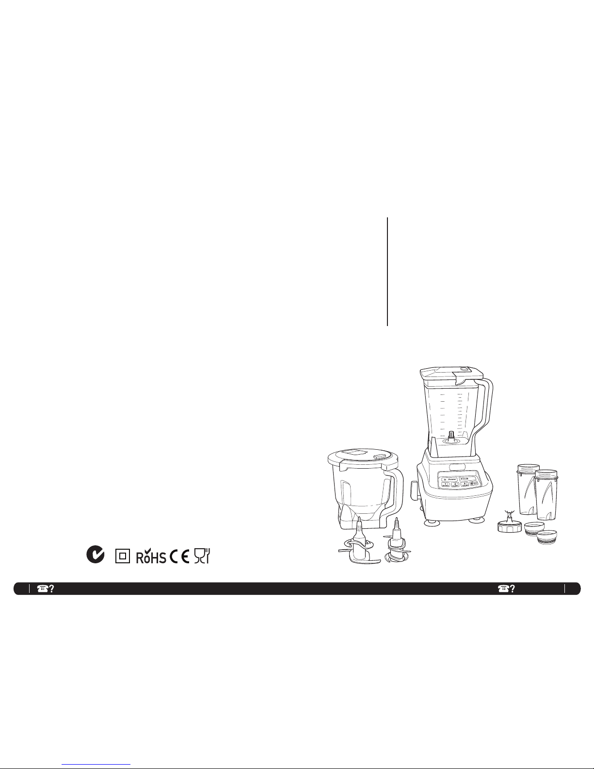
The Ninja® Mega Kitchen System is a professional, high powered innovative tool with a sleek design and
outstanding performance, a true asset to any kitchen. It is per fect for ice crushing, blending, foo d mixing,
and complete juicing. The Ninja
®
Mega Kitchen System also features a unique capabilit y to knead dough for
pizzas, breads, pretzels and cookie s! Create all of your favourite recipe s fast and easy with just one touch of a
button. For best results, be sure to carefully read all the instructions contained in the manual before using this
appliance.
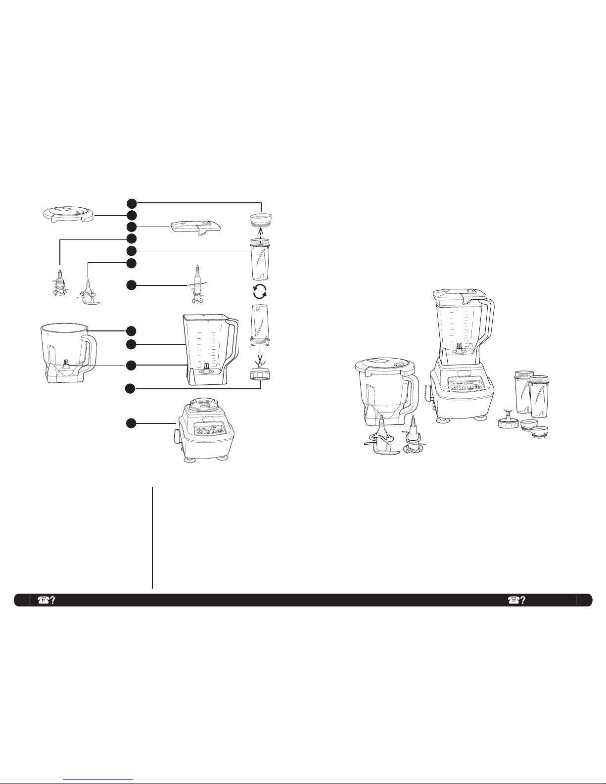
h 1.89 L Bowl
i 2.15 L Pitcher
j Gear Shaft
k Single Serve Blade
l Motor Base
m Power Cord (not shown)
a To-Go Single Serve Lid (x2)
b Bowl Lid with Locking Handle
c Pitcher Lid with Locking Handle
d 4-Blade Assembly (bowl)
e Single Serve Drink Cup (x 2)
f Dough Blade (bowl)
g 6-Blade Assembly (pitcher)
FEAT URES:
• Patented Pitcher
• 1.89 L Bowl with Driz zle Hole
• Single Serve Drink Cup
• Lock– In Lid, Fe aturing Pour Spout
• Easy to Clean Elec tronic Control Pan el
• Sturdy, Non-Slip Base
• Hidde n Drain Holes - prevent water build u p from dishwasher
NOTE: Attachments are not interchangeable.
Getting To Know Your Ninja® Mega Kitchen System
a
d
e
b
c
f
g
h
i
k
j
l
Page 5

7 8
AUST: 1800 89 0 840 NZ: 080 0 002 999
Using the Ninja® Mega Kitchen System
BEFORE FIRST USE
1 Remove all packaging material and labels
from the appliance.
2 Wash the lids, pitcher, bowl, single serve cups
and attachments in warm, soapy water with a
soft cloth. Use caution when washing the
blade assemblies as the blades are ver y
sharp.
3 Rinse and dry thoroughly.
4 The pitcher, bowl, single ser ve cups, lids and
attachments, are all dishwasher safe. It is
recommended that the lids and attachments
be placed on the top rack. Ensure that the
attachments are removed from the containers
before placing in the dishwasher.
5 Wipe the motor base clean with a damp cloth.
PLEASE KEEP THESE IMPORTANT
SAFEGUARDS IN MIND WHEN
USING THE APPLIANCE:
IMPORTANT: Never add ingredients
into the container before placing the
attachment in first.
IMPORTANT: Attachments are not
interchangeable.
CAUTION: Blades are sharp! Use
extreme caution when handling the blade
assemblies. Always hold them by the
shaft.
IMPORTANT: DO NOT attempt to
operate the appliance without the lid on.
IMPORTANT: Never run the appliance
empty.
CAUTION: Use extreme caution when
blending hot foods to avoid accidental
scalding or burns. Do not blend food
that is hotter than 82°C. Allow very hot
ingredients to cool before blending.
WARNING: Secure the appliance while in
use by pressing down on the lid with one
hand.
CAUTION: Never remove the container
while the appliance is still running.
WARNING: Never leave the appliance
unattended while in use.
Fig. 3b
Fig. 2
Fig. 1
Assembly and Use for the 2.15 L Pitcher
IMPORTANT: Make sure that the motor base is
plugged in for use.
1 Place the motor base on a clean, dry, level
surface such as a counter or table top.
2 Align and lower the Pitcher onto the motor
base. (Fig. 1) Handle should be aligned slightly
to the right of the “LOCK” symbol on the
motor base.
3 Rotate the pitcher clockwise as far as it will go
to lock in place. (Fig. 2)
4 The pitcher can be placed on the motor base
two ways; the handle can be on the front right
corner or the front left corner.
(Fig. 3a, Fig. 3b)
5 Holding the 6-Blade Assembly by the top of the
shaft, place it onto the drive gear inside the
pitcher. Ensure that the attachment is seated
properly and is standing upright. (Fig. 4)
NOTE: The blade will fit loosely on the drive
gea r.
6 Add the ingredients to the pitcher, making sure
not to overfill.
NOTE: Do not exceed the highest measured
marking line on the side of the pitcher.
NOTE: If you need to add additional ingredients
while the appliance is blending, open the pour
spout cap and pour the ingredients in through
the opening.
7 Plug the power cord into the electrical outlet
and press the power button (
).
NOTE: As a safety feature, the power
button (
) will flash and the motor will not
work if the pitcher and lid are not installed
correctly. When the pitcher and lid are
installed properly, the power button (
)
will be solid, indicating that the appliance
is ready for use.
8 Holding the lid by the handle in the upright
position, place it on top of the pitcher aligning
the arrow (
) located on the lid with the arrow
(
) located on the pitcher’s handle. (Fig. 5)
Press the handle down until you hear a click.
Fig. 4
Fig. 5
Assembly
Fig. 3a
Page 6

9 10
AUST: 1800 89 0 840 NZ: 080 0 002 999
9 Select the speed that best suits your needs.
(Fig. 6)
NOTE: Pulse ingredients for even blending by
pressing down in short intervals.
10 When you have reached your desired
consistency, stop the appliance by pressing
the power button
( ) and wait for the
attachment to stop turning. (Fig. 7)
11 To remove the lid, press the release button on
the lid, pull the lid handle up to a 90° angle
and lift the lid off. Turn the pitcher counter
clockwise and then lift off the base.
(Fig. 7, Fig. 8)
CAUTION: Never insert your hands in the
pitcher as the blades are sharp. Always use a
spatula to dislodge food that has stuck to the
sides of the pitcher.
Assembly and Use for the 2.15 L Pitcher - cont.
Fig. 7
USE
REMOVAL
Fig. 6
Fig. 8
12 Depending on the consistency of the contents
in the container, open the pour spout cap
and use the spout to empty liquid contents.
For thicker consistencies, remove the lid and
attachment carefully (by its shaft), then empty
contents from the container.
13 Make sure that the unit is unplugged when
not in use.
IMPORTANT: Make sure that the motor base
is plugged in for use.
1 Place the motor base on a clean, dry, level
surface such as a counter or table top.
2 Add ingredients to the single serve cup.
3 Place the single serve blade onto the cup and
screw it tightly until you have a good seal.
(Fig. 1)
4 Turn the single serve cup upside down and
place it onto the motor base, aligning the
tabs on the cup with the motor base. Turn the
single serve cup clockwise. (Fig. 2) Turn the
power button on, the single serve button will
illuminate.
5 Press down on the Single Serve but ton in
short intervals to activate. (Fig. 3)
Fig. 1
Fig. 2
Assembly and Use for the Single Serve Cup
Fig. 3
Fig. 4
Fig. 5
ASSEMBLY USE REMOVAL
For best results, use short “PULS ES”... Practice makes perfec t!!
6 Once you have reached your desired
consistency, turn the power button off. Turn
the single serve cup counter clockwise and
pull straight up to remove. (Fig. 4) (Fig. 5)
NOTE: Do not overfill! To avoid spilling, do
not add ingredients past the “Max” fill line.
7 Turn the cup upright and remove the single
serve blade by t wisting the blade assembly
clockwise.
8 Place the To-Go drinking lid onto the single
serve drink cup, twist to seal and enjoy!
9 Make sure that the motor base is unplugged
when not in use.
Page 7

11 12
AUST: 1800 89 0 840 NZ: 080 0 002 999
Fig. 1
Fig. 2
Assembly and Use for the 1.89 L Bowl
ASSEMBLY
Fig. 3a
Fig. 3b
USING THE 4-BLADE ASSEMBLY
1 Holding the 4-Blade assembly by the shaft, place it
onto the gear shaft inside the bowl. Ensure that the
attachment fits around the gear shaft and that it is
standing straight.
2 Add the ingredients and secure the bowl lid onto
the bowl. (Fig. 1)
3 Plug the power cord into the electrical outlet and
press on the power button (
).
4 Select the speed that best suits your needs. Pulse
ingredients evenly by pressing down in short
intervals.
NOTE: Please refer to “Speed Settings & Uses”
chart for suggested uses and speeds.
5 When you have reached your desired consistency,
stop the appliance by pressing the power button (
) and wait for the blade to stop turning.
6 To remove the lid, pull the lid handle up to a 90°
angle and lift the lid off. Turn the bowl counter
clockwise and then lift off the base. (Fig. 2, Fig. 3)
NOTE: Do not exceed the highest measured
marking. For meats, do not exceed 1.0L marking.
Fig. 1
Suction
Lever
Fig. 4
USE
Activat e
Suction
Release
Suction
Fig. 4a
Fig. 4b
IMPORTANT: Make sure that the motor base is
plugged in for use.
1 Place the motor base on a clean, dry, level surface
such as a counter or table top.
2 Align and lower the Bowl onto the motor base.
(Fig. 1) Handle should be aligned slightly to the
right of the “LOCK” symbol on the motor base.
3 Rotate the bowl clockwise as far as it will go to
lock in place. (Fig. 2)
4 The bowl can be placed on the motor base t wo
ways; the handle can be on the front right corner or
the front left corner. (Fig. 3a, Fig. 3b)
5 Holding the desired blade by the top of the shaft,
place it onto the drive gear inside the bowl. Ensure
that the attachment is seated properly and is
standing upright. (Fig. 4)
NOTE: The blade will fit loosely on the drive gear.
6 Add the ingredients to the bowl, making sure that
they do not exceed the highest measured marking
line on the side of the bowl.
7 Plug the power cord into the electrical outlet and
press the power button (
).
NOTE: As a safety feature, the power button
(
) will flash and the motor will not work if
the bowl and lid are not installed correctly.
When the bowl and lid are installed properly,
the power button (
) will be solid, indicating
that the appliance is ready for use.
8 Holding the lid by the handle in the upright
position, place it on top of the bowl aligning the
arrow (
) located on the lid with the arrow
( ) located on the bowl’s handle. (Fig. 5) Press the
handle down until you hear a click.
NOTE: The 1.89 L bowl is not intended for
blending drinks. Do not overfill.
NOTE: To add liquids during blending, open the
drizzle hole on the top of the lid and pour the liquid
slowly into the mixture.
NOTE: Do not exceed the
highest measured marking line
on the side of the bowl. For
meats do not exceed 1.0L bowl
mark.
Fig. 4
Fig. 5
USING THE DOUGH BLADE
IMPORTANT: Use only the “DOUGH” button when
using this attachment.
IMPORTANT: Use the suction lever when using the
dough blade on SPEED 1/DOUGH.
1 Place the motor base on a clean, dry, level surface
such as a counter or table top. (Fig. 4) Push the
suction lever on the side of the motor base down
to secure the suction feet to the sur face. (Fig. 4a)
If the suction feet have not totally adhered to the
surface, press down lightly on the base to give the
suction feet a better grip.
2 Secure the bowl onto the motor base.
3 Holding the dough blade by the shaft, place it onto
the gear shaft inside the bowl. Ensure that the
attachment fits around the gear shaft and that it is
standing straight.
4 Add the ingredients and secure the bowl lid onto
the bowl.
NOTE: For best results add wet ingredients first
and then add dry ingredients.
5 Plug the power cord into the electrical outlet and
press on the power button (
).
6 Once finished making dough, remove the bowl
from the motor base. (Fig. 2, Fig. 3)
7 To release the motor base from the counter or table
top, pull the suction lever up to release the suction
feet. (Fig. 4b)
NOTE: The suction lever activates the suction feet
for added stability.
Fig. 2
Fig. 3
REMOVAL
USE
Page 8

13 14
AUST: 1800 89 0 840 NZ: 080 0 002 999
HOW TO CLEAN
CAUTION: Make sure that the motor base
is unplugged from the power source before
inserting or removing any attachment and before
cleaning.
CAUTION: DO NOT immerse the motor base into
water or any other liquid.
1 Separate/remove all parts from each other.
2 Clean the motor base with a damp cloth and wipe
dry.
3 Place the pitcher, single serve cup and bowl in
the dishwasher. Place the lids and attachments
on the top rack. Use caution when handling
the blade assemblies as the blades are very
sharp.
NOTE: You may also wash the containers by
filling ¾ of the container with warm water and
a drop of dish washing detergent, placing the
corresponding lid on the container and pressing
the pulse button a few times. Once clean,
remove the container from the motor base. Rinse
the container, attachment and lid under running
water. Allow all the parts to dry before storing.
Care & Maintenance
HOW TO STORE
1 Store the Ninja® Mega Kitchen System upright
with the pitcher on the motor base, 6-Blade
assembly inside the pitcher and lid on the pitcher.
Do not place anything on top. Store the bowl with
the 4-Blade assembly inside and the lid on top.
S
tore the single ser ve cup and the rest of the
attachments along side the appliance or in a
cabinet where they will not be damaged and
won’t cause a hazard.
RESETTING THE MOTOR THERMOSTAT
The Ninja
®
Mega Kitchen System features a
unique safety system which prevents damage
to the unit’s motor and drive system should
you inadvertently overload your appliance. If
the appliance is being overloaded, the motor
will stop and the power light will remain lit
and speeds 1, 2 and 3 will flash. To reset the
appliance, follow the resetting procedure
below:
1 Unplug the appliance from the electrical
outlet.
2 Remove and empty the container and ensure
that no food is jamming the cutting blades or
attachments.
3 Allow the appliance to cool for approximately
30 minutes.
4 Re-install the container onto the base and re-
plug the appliance into the electrical outlet.
5 Proceed to use the appliance as before
making sure not to exceed the recommended
maximum capacities.
FUNCTION CONTAINER ATTACHMENT
SPEED
BUTTON
TYPE OF FOOD
Single Serve
Blending
Single Serve Cup Single Serve Blade Single Serve
Smoothies
Frappes
Milk Shakes
Mincing Single Serve Cup Single Serve Blade Single Serve
Onion
Garlic
Herbs
Kneading Bowl Dough Blade 1
Bread dough
Pie dough
Pizza dough
Pretzel dough
Dough Mixing Bowl Dough Blade 1 Cookie dough
Blending
Pitcher/Bowl
Single Serve Cup
Blade Assembly
Single Serve Blade
2
Pulse
Single Serve
Pâtés
Stewed fruits
Dips
Apple sauce
Spreads
Soups
Baby food
Emulsifying Bowl Blade Assembly 2
Salad Dressings
Dips
Sauces
Grinding Bowl Blade Assembly 2 Meat
Grating
Bowl
Single Serve Cup
Blade Assembly
Single Serve Blade
3 or Pulse
Single Serve
Grated cheese
Bread crumbs
Spices
Fine Blending
Bowl
Single Serve Cup
Pitcher
Blade Assembly
Single Serve Blade
Pulse
Single Serve
3
Salsa
Vegetables
Nuts
Mixing Bowl Dough Blade 1
Light cake mixes
Batters
Ice Crushing
Pitcher
Single Serve Cup
Blade Assembly
Single Serve Blade3 Single Serve
Ice
Pureeing
Pitcher
Single Serve Cup
Blade Assembly
Single Serve Blade3 Single Serve
Smoothies
Smooth soups
Milkshakes
Speed Setting & Uses
IMPORTANT: Use the suction lever when using the dough blade on SPEED 1/DOUGH.
Page 9

15 16
AUST: 1800 89 0 840 NZ: 080 0 002 999
PROBLEMS POSSIBLE REASONS & SOLUTIONS
Motor Doesn’t Start or
Attachment Doesn’t Rotate.
Make sure the container is se curely placed on motor base.
Make sure the lid is securely on container in the correc t position (align
arrows).
The applian ce is turned “Off”. Press the power button (
) to turn “O n”.
Check that th e plug is securely inser ted into the electrical outlet .
Check the fu se or circuit breaker.
The unit has overloaded. T he appliance will stop and the power ligh t
will remain on w hile speeds 1, 2 and 3 w ill flash. Unplug and wait
approximately 30 minutes before using again.
The unit has overheated. Unplug and wait a pproximate ly 30 minutes
before using again.
Check to make sure the unit is not ove rloaded.
Food is Unevenly Blended.
Either you are blending too much food at on e time, or the pieces are not of
even size and blending smaller a mounts per batch.
Food is Blended Too Fine or is
Too W ater y.
The food has b een over blended. Use pulse button for controlled blendin g.
Food Collects On Lid or On the
Sides of the Container.
The mixtu re is to thick. Add more liquid.
You Cannot Achieve Snow
From Solid Ice.
Do not use ice that has been sit ting out or has starte d to melt. Use ice
straight from the freezer.
Motor Base Won’t Stick to
Counter or Table Top.
Make sure surface and suct ion feet are wiped clean . Suction fe et will only
stick to smooth surface s. Suction feet WILL NOT stick on so me surface s
such as, wood , tile and non-polishe d finishes.
DO NOT attempt to use applian ce when the motor ba se is stuc k to
a surfac e that is not secure, (cu tting b oard, pl atter, plates, etc.).
Troubleshooting Guide
Notes
Page 10

17 18
AUST: 1800 89 0 840 NZ: 080 0 002 999
Notes
ONE (1) YEAR
LIMITED REPLACEMENT WARRANTY STATEMENT
If your product becomes defective due to faulty material or workmanship within a period of 1 year from
the date of purchase, we warrant to do the following:
• For New Zealand Consumers: We will replace the product with a new product, free of charge, or
repair the product at our cost, at our discretion.
• For Australian Consumers: Our goods come with guarantees that cannot be excluded under the
Australian Consumer Law. You are entitled to a replacement or refund for a major failure and for
compensation for any other reasonably foreseeable loss or damage. You are also entitled to have
the goods repaired or replaced if the goods fail to be of acceptable quality and the failure does
not amount to a major failure.
Your warranty is subject to the following conditions:
• DO NOT operate the appliance with a damaged plug or cord, or if the unit has been dropped,
damaged or dropped in water. To avoid the risk of electric shock, do not disassemble or attempt
to repair the appliance on your own. If the supply cord is damaged, it must be replaced by a
qualified electrician in order to avoid a hazard. Incorrect re-assembly or repair can cause a
risk of electrical shock or injury to persons when the appliance is used.
• The product has not been misused, abused, neglected, altered, modified or repaired by anyone.
• The product has been subjected to fair wear and tear.
• The product has not been used for trade, professional or hire purposes.
• The product has not sustained damage through foreign objects, substances or accident.
Your warranty does not cover:
• Components that are subject to natural wear and tear caused by normal use in accordance with
operating instructions.
• Unauthorised/improper maintenance/handling or overload is excluded from this warranty.
• For guarantee claims you will need to submit a proof of purchase in the form of a valid receipt
that displays date and place of purchase.
This warranty does not replace but is in addition to your statutory rights.
This warranty does not apply to accessories supplied with the product.
This warranty applies only to the original purchaser and may not be transferred.
Replacement products will be covered by the limited warranty for the balance of the warranty period
from the date of the original purchase.
Please note:
Only defective product or parts returned to place of purchase will be replaced under this warranty.
New Zealand Contact: Australia Contact
Brand Developers Limited Brand Developers Aust Pty Ltd
Unit H, 686 Rosebank Road, 461 Plummer Street,
Avondale 1026, Auckland, New Zealand PORT MELBOURNE, VIC 3207
FAX: +64 9 306 8203 FAX: +61 3 9681 7825
NZ Customer Care 0800 002 999 AUST Customer Care: 1800 890 840
Page 11

Copyright © 2013 Euro-Pro Operating LLC
Printed in China
Illustrations may differ from actual product.
BL770NZ 30.E.130607.1
Euro-Pro and Ninja are trademarks of Euro-Pro Operating LLC.
Z854
 Loading...