

SOLAR BOOSTER D, EH
Instruction manual ..................................... 3 - 32
Betriebsanleitung ...................................... 33 - 62
Manuel d’Instructions ................................ 63 - 92
Gebruikershandleiding .............................. 93 - 122
Manual de instrucciones ........................... 123 - 152
Manuale di istruzioni ................................. 153 - 182
Руководство ............................................. 183 - 211
Üzemeltetési útmutató .............................. 212 - 238

Index
1 Safety precautions and warnings .....................................................................................4
2 Description 2.1 Application ..............................................................................6
2.2 Operation elements ................................................................6
3 Installation 3.1 Temperature conditions ..........................................................6
3.2 Condition of distance ..............................................................7
3.3
3.4 Mounting of handle .................................................................7
3.5 Mounting of spacers ...............................................................7
3.6 Water connection ....................................................................8
3.7 Mains power connection .........................................................8
3.8 High pressure connection .......................................................9
3.9 Venting - D models ..............................................................10
3.10 Venting - EH models ............................................................11
3.11 Connecting to external fuel supply - D-models .....................12
4 Operation 4.1 Connections .........................................................................13
4.1.1 High pressure hose - directly on the machine ...........13
4.1.2 High pressure hose - to outlet point ...........................13
4.1.3 Spray handle - accessories .......................................14
4.1.4 Selection of spray lance .............................................14
4.1.5 Application of detergents (external injector) ..............15
4.1.6 Application of detergents (internal) (optional) ............16
4.2 Running the SOLAR BOOSTER ..........................................16
4.2.1 Starting up .................................................................16
4.2.2 Automatic start/stop ...................................................17
4.2.3 Running with hot water ..............................................17
4.2.4 Double spray lance, pressure regulation ...................18
4.2.5 Stop ...........................................................................18
4.2.6 Automatic system "shut-down" ..................................19
4.2.7 Frost protection ..........................................................19
Mounting of feet and levelling of machine ..............................7
5 Fields of Application 5.1 Fields of application ..............................................................20
and Working Methods 5.2 Working pressure .................................................................20
5.3 Temperature .........................................................................20
5.4 Mechanical impact ................................................................20
5.5 Detergents ............................................................................21
5.6 Working methods .................................................................22
5.7 Typical cleaning tasks ...........................................................23
5.7.1 Agriculture .................................................................23
5.7.2 Vehicles .....................................................................23
5.7.3 Building and equipment .............................................24
6 Maintenance 6.1 Hour counters .......................................................................25
6.2 Oil ...................................................................................25
6.3 Water fi lter ............................................................................25
6.4 Cleaning of high pressure nozzle .........................................26
6.5 Fuel fi lter - D models only .....................................................26
6.6 Disposable waste .................................................................26
7 Trouble Shooting 7.1 General trouble shooting - all SOLAR BOOSTER models ...27
7.2 Error messages, SOLAR BOOSTER EH
(el. heated) models ...............................................................29
7.3 Error mesages, SOLAR BOOSTER D
(diesel heated) models .........................................................30
8 Technical Data .....................................................................................................31
9 Warranty .....................................................................................................32
10 EC Declaration of Conformity ...................................................................................32
3

1 Safety Precautions and Warnings
Before starting up your high
pressure hot water washer for
the fi rst time, this instruction
manual must be read through
carefully. Save the instructions
for later use.
Only let instructed people operate the machine.
General
When using the high pressure
hot water washer all existing
national regulations must be
observed. Beyond the instruction manual and the current
national legal regulations for
prevention of accidents, also
the approved rules for safe
working must be observed.
Any method of use endangering
the safety of persons or equipment is forbidden.
Before use
Before starting up your high
pressure hot water washer
check that it is in a regular
condition. Electric plugs and
couplings must be watertight.
Check the electric cables at
regular intervals for damage
and wear. Only use the high
pressure hot water washer if the
electric cable is all right (damaged electric cables can cause
electric shock!)
Important instructions
Connection to public drinking
water supply must be performed in accordance with the
applicable regulations in your
country.
IMPORTANT: Only use water
without impurities!
Before each use of your high
pressure hot water washer
check the most important visual
parts.
High pressure jets can be
dangerous if misused. Never
direct the water jet towards people, pets, electric wiring, or the
machine itself.
Spray handle and lance are affected by a thrust during operation - therefore always hold the
spray lance fi rmly with both
hands.
Never try to clean clothes or
footwear on yourself or other
persons.
Operator and anyone in immediate vicinity of the site of cleaning should take action to protect
himself from being struck by
debris dislodged during operation.
Check that cleaning will not
result in dangerous substances
(e.g. asbestos, oil) being
washed off the object to be
cleaned and harming the environment.
Do not clean sensitive surfaces
made of rubber, fabrics or the
like with the zero nozzle. With
the fl at jet nozzle keep a distance of at least 15 cm to the
surface to be cleaned.
Never let children operate the
machine.
Do not use the machine if the
electric cable or the high pressure hose are damaged.
Do not cover the machine during operation or use it in a room
without adequate ventilation !
If any of the machines overload protection devices trips
(machine stops unintended),
release the trigger of the spray
handle. Lock the spray handle
with locking device and turn
the start/stop switch to position
„OFF“.
Refer to section "7 Trouble
Shooting".
The machine must be placed in
a room where it is not exposed
to frost.
Never start the cleaner without
water supply. Even a short water defi ciency can damage the
sleeves of the pump.
Operation
Avoid damage to the electric
cables such as squeezing, pulling, knots etc. and keep them
away from sharp or hot objects.
Avoid damage to the high pressure hose such as running over
by vehicles, squeezing, pulling,
knots/kinks etc. and keep it
away from oil and sharp or hot
objects, as such may cause the
hose to burst.
4

The cleaner can be used in
zones classifi ed as ZONE 2.
Important! Never use the
machine in an environment
where there could be a danger of explosion (according to
EN-50014).
Important! When the system
has been in operation and
thereafter stopped, there might
still be a working pressure in
the pipeline and high pressure
hoses. Therefore you should
pay special attention to the following:
• Never dismount the high
pressure hose from the
machine during operation.
Disconnect the machine,
close the shut-off cock and
relieve the high pressure
hose of pressure prior to
dismounting.
• Never dismount the high
pressure hose from the outlet point before it has been
securely closed and the high
pressure hose has been
relieved of pressure.
• Prior to any service interference in the machine it
should be disconnected and
the system relieved of pressure by activating the trigger
of the spray handle.
Repair and Maintenance
Only carry through the maintenance operations described in
the operating instructions. Only
use original Nilfi sk-ALTO spare
parts.
Do NOT make any technical
modifi cations to the high pressure hot water washer.
Warning! High pressure hoses,
nozzles and couplings are
important for the safety when
operating the machine. Only
use the high pressure hoses,
nozzles and couplings pre-
scribed by Nilfi sk-ALTO!
For major repairs, please contact your nearest Nilfi sk-ALTO
service organisation.
Mains power connection
This product is intended for
stationary installation only
and is supplied without a
power cord! Only let an authorized electrician connect
the machine to the mains
supply !
The following points must be
observed:
• Check that the voltage
stated on the data plate
corresponds to your mains
voltage.
• Make sure that the power
cord contains the right
number of wires (including
ground wire) and that each
wire has the right dimensions to carry the load (amperage) stated on the data
plate of the machine.
• Make sure that the installation (cables, connection
points and fuses) is correctly
dimensioned for the load of
the machine - refer to the
data plate of the machine.
If not required by local legislation, we strongly recommend you to connect the
machine to a power source
with a Residual Current Device (RCD) which will disconnect the power supply if the
leakage current exceeds 30
mA for 20 milli seconds !
See section "3.5 Mains power
connection" for further instruc-
tions.
Only let a qualifi ed electrician
maintain the electric installation.
Safety Devices
Safety Valve
The pressure side of the high
pressure pump is fi tted with a
safety valve. This valve leads
the water back to the suction
side of the pump when the
spray handle is closed or if a
nozzle is blocked.
The safety valve is adjusted
and sealed by the producer.
THIS ADJUSTMENT MUST
NOT BE CHANGED !
Machine protection
The machine features an overcurrent protection and built-in
thermal protection of the motor.
In the event of increased power
consumption (maloperation)
and in the event of excessive
motor temperature (obstructed
ventilation etc.), the entire
machine will automatically be
disconnected from the mains
supply.
Short circuit protection
The machine is equipped with
a short-circuit protection. In the
event of short-circuits in the
machine, the protective device
will disconnect the entire machine from the mains supply.
5
2 Description
2.1 Application
2.2 Operation elements
This high pressure hot water
washer has been developed
for stationary installation and
professional use within:
- agriculture
- light industry
- transport
- building and construction
- service
Section 4 describes how to use
the high pressure hot water
washer.
See illustration at the end of the manual
1 High pressure outlet (quick coupling, male)
2 Main switch
3 Start push button (illuminated, green)
4 Stop push button (illuminated, red)
5 Heating ON/OFF push button (illuminated, yellow)
6 Pressure gauge
7 Water inlet (quick coupling, female)
8 Thermostat (temperature adjustment)
9 Electric cable
10 Inspection window (hour counters, error messages)
11 Overheat fuse - resetable
12 Chimney
Only use the high pressure
hot water washer for purposes
described in this manual.
The safety precautions must be
observed to prevent damage
to the machine, the surface to
be cleaned or severe personal
injuries.
3 Installation
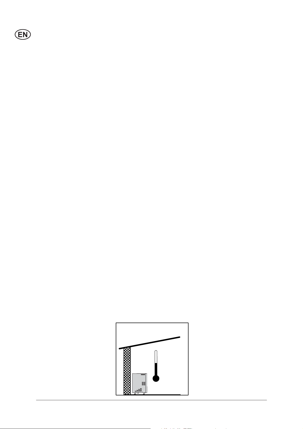
3.1 Temperature conditions
6
Max 40 °C
Min 2 °C
The machine should be installed in a frost-free room.
This applies to pump as well as
pipelines incl. of outlet points.
If connected to outdoor outlet
points it should be possible to
close and emp ty that part of the
line which is exposed to frost.
The maximum ambient temperature for the machine is 40°C.
3.2 Condition of distance
Min. 150 mm
Min. 500 mm
In consideration of the cooling
system of the machine and the
accessibility of service, there
must be free wall space on both
sides of the machine. To the
right 500 mm at a min i mum and
to the left 150 mm at a min i mum. To the ceiling there must
be at least 1000 mm and from
the rear point of the machine to
the back wall there must be at
least 100 mm. There must not
be any other objects in this area
either, such as pipes etc.
3.3 Mounting of feet and
levelling of machine
3.4
Mounting of handle
The machine is delivered
without feet mounted. Loosen
the machine from the pallet and
mount the 4 feet by fastening
them to the fl ange underneath
the machine by means of a 19
mm open-end wrench.
Place the machine on a plane
fl oor.
To level the machine, loosen
the lock nut on the appropriate
feet and adjust the height by
screwing the foot up or down.
Next cross-tighten the lock nuts
around the fl ange. It is important that all 4 feet are in contact
with the fl oor.
Mount the enclosed handles on
°
0
the machine by pressing them
°
C
85°
into the suitable openings in the
60°
80°
cabinet.
3.5 Mounting of spacers
Mount the enclosed spacers at
the back of the machine.
7
1
T
3.6 Water connection
that the water supply is within
7
the following specifi cations and
that the water does not contain
particles such as fl oating sand.
Min. water inlet pressure: 1 bar
(at the required fl ow rate of the
°
0
20°
°
C
40°
85°
60°
80°
machine - see data plate.
Max. water pressure: 10 bar
Max. water inlet temp. (EH/GH):
85°C.
Max. water inlet temp. (D/G):
30°C.
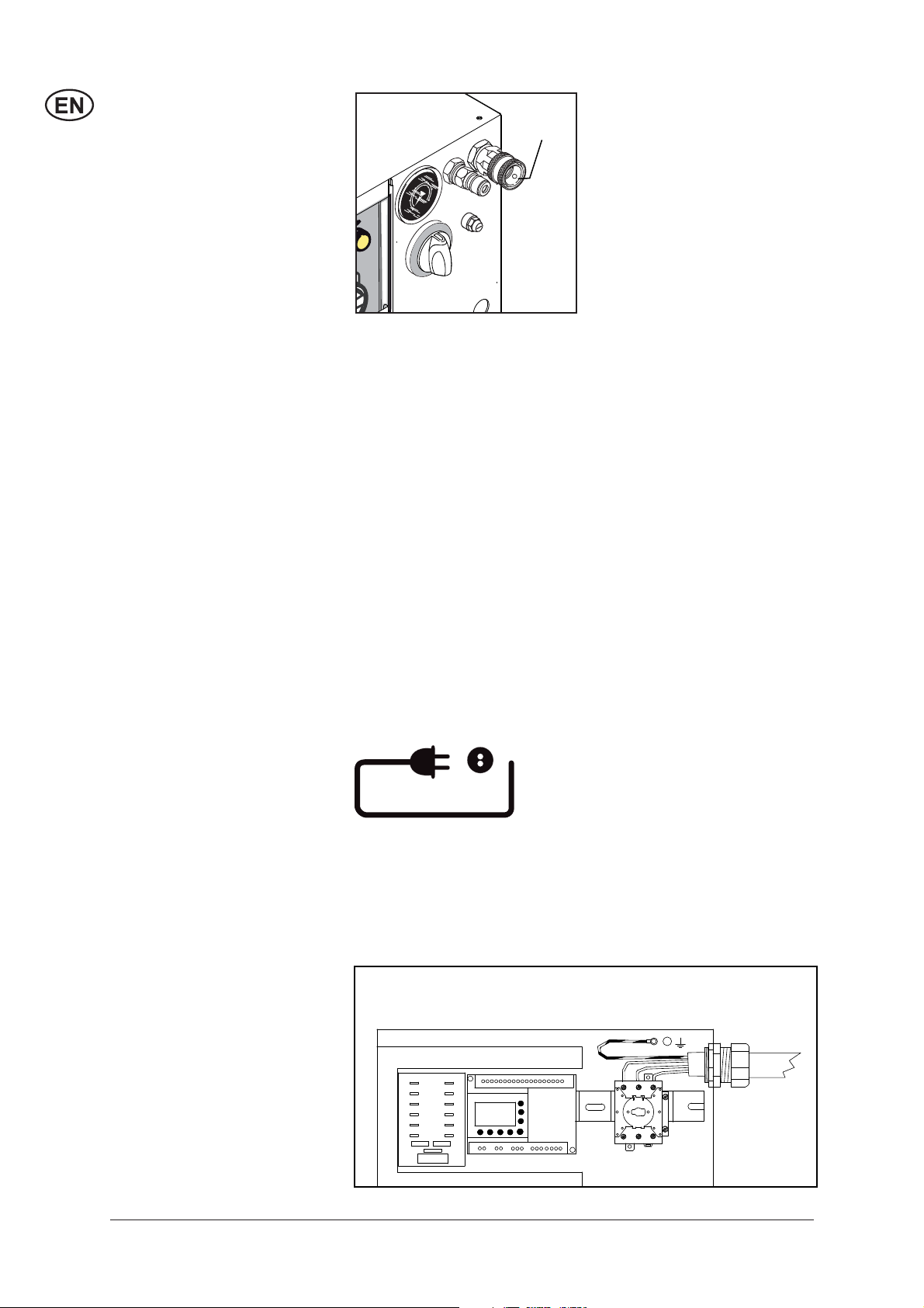
3.7 Mains power
connection
The water connection is made
through a fl exible hose connected to the quick cou pling on the
water inlet (7) of the machine.
Make sure that the supply
hose is suited for the purpose
(temperature and fl ow rate). If
in doubt, contact your Nilfi skALTO representative.
The connection can be made to
a public drinking water supply
network or a private water sup ply. A shut-off cock should be
mounted on the water supply
network in the immediate vicinity of the ma chine. Make sure
All SOLAR BOOSTER feature
a water tank, and no further
protection against back-fl owing
water into the supply network is
required. The machine complies
with EN 1717.
If there is a risk of fl oating sand
or other impurities in the inlet
water, a sand fi lter (50 micron)
should be mounted between the
supply outlet and the internal
fi lter of the machine.
Clean the water inlet fi lter (7)
once a month or in case of
poor throughput (inlet pressure below 1 bar at the fl ow rate
required by the machine).
The following precautions must
be observed:
• Make sure that the supply
cable is of the correct dimen-
CAUTION! An authorized electrician must perform the electrical connection of the machine
to the main power supply. Refer
sion (see voltage and load on
the data plate of the machine)
and is suitable for the specifi c
environment.
to section "1 Safety precau-
tions and warnings".
106420051
12
11
10
9
8
7
F 10
8
6
A
4
3
2
-
B
+
5
4
3
AA1
2
1
F5
15
12
9
7
8
5
14
11
101
13
6
MITSUBISHI
Pump plc
A2
135L1 L2 L3
T
T22T1 4 6T3
3.8 High pressure
connection
• Guide the supply cable
through the strain relief grommet on the frame (9) and
through the strain relief grommet on the electric box into
the electric box.
• Connect the phase cords of
the supply cable to the connection terminals L1(1), L2(3)
and L3(5) of the main switch
of the machine. For single
phase machines use L1(1)
and L2(3) to connect phase
and zero cords.
• Connect protective earth
wire to the terminal marked
and located above the main
switch on the metal chassis
(6). Ensure the connection by
the use of toothed washers.
• Check and measure the
protective earth connection
according to legislation.
• Connect the other end of the
cable to an approved socket
of a correct dimensioned
main supply.
Make sure that the cable is
properly guided and relieved
between the fi xed installation
and the machine and that the
cable is without any damage to
the insulation.
Also see notes in section "1
Safety precautions and warnings"!
The outlet of the machine (1)
can be connected directly to a
1
standard high pressure hose (a)
or to a pipeline with fi xed outlet
points (c).
c
°
0
20°
°
C
40°
85°
°
60
80°
a
a
IMPORTANT: When connecting
to a pipeline always use a fl exible hose connection from the
outlet of the machine (pos. 1).
Contact your Nilfi sk-ALTO distributor for further information
about hose dimension.
It is recommended to let a
service tech ni cian authorized
by Nilfi sk-ALTO prepare the
pipeline.
9
3.9 Venting
2
0°
0
°
C
°
8
5
°
8
0
°
6
0
°
4
0°
(D models)
4
3
2
When the SOLAR BOOSTER
is properly connected to supply water, electrical installation
and a high pressure hose (or
pipeline) the high pressure
pump must be vented before it
is operational.
1. Turn the main switch, (2) to
position “ON”.
2. Push the “START” button (3),
and the SOLAR BOOSTER
will start.
3. Open the outlet point (spray
handle on high pressure
hose, (d) or outlet on piping
system (e) without having a
spray lance connected.
ON
4. Let the water run until all air
has escaped from the pump
(even water fl ow).
5. In the case of a recently
installed piping sys tem, or if
the pipeline and the pump
have been emptied in any
other way, the system should
be vented by starting the
pump and then letting the
water run at each outlet point
of the pipeline at turns. It is
recommended to begin with
°
0
°
20
°
C
°
40
°
85
°
°
60
80
d
e
the most distant outlet (height
and/or length).
6. When con nect ing the high
pressure hose directly to the
ma chine, starting the pump
and activating the trigger
of the spray handle without
having attached the spray
lance, you should vent the
system.
7. Stop the SOLAR BOOSTER
by pressing the "STOP" push
button (4).
The SOLAR BOOSTER is now
vented.
10
3.10 Venting - SOLAR
2
0°
0
°
C
°
8
5
°
8
0
°
6
0
°
4
0°
BOOSTER EH models
4
3
85
2
When the SOLAR BOOSTER
is properly connected to supply water, electrical installation
and a high pressure hose (or
pipeline) the high pressure
pump must be vented before it
is operational.
3. Otherwise push the “START”
button (3), and the SOLAR
BOOSTER will start.
4. Open the outlet point - spray
handle on high pressure
hose, (d) or outlet on piping
system (e) without having a
spray lance connected.
1. Turn on the water inlet and
wait until the water tank has
been fi lled with water.
2. Turn the main switch (2), to
position "ON".
5. Let the water run until all air
has escaped from the pump
(even water fl ow). If little or no
water fl ows from the system,
it may be necessary to vent
the internal feed pump separately. The Nilfi sk-ALTO service technician should perform
°
ON
0
°
20
°
C
°
40
°
°
°
60
80
this by loosening the centre
screw on the feed pump, see
arrow.
6. In the case of a recently installed piping system, or if the
pipeline and the pump have
been emptied in any other
way, the system should be
vented by starting the pump
and then letting the water run
at each outlet point of the
pipeline at turns. It is recommended to begin with most
e
d
distant outlet (height and/or
length).
7. When connecting the high
pressure hose directly to the
machine, starting the pump
and activating the trigger of
the spray handle without having attached the spray lance
should vent the system.
8. Stop the SOLAR BOOSTER
by pressing the “STOP” push
button (4).
The SOLAR BOOSTER is now
vented.
11

3.11 Connecting to external
fuel supply –
D-models
All SOLAR BOOSTER D- models must be connected to an
external fuel supply (canister or
tank) as no internal
provision is made for storing
fuel.
You can choose between oneand two-string connection,
where "one"-string only has one
supply hose (a) and "two"-string
has an additional return hose
(b) - see illustration.
Please observe that in some
a
b
countries only the "one" string
system is approved.
The fuel hose(s) should be
guided through the rubber
grommet(s) in the chassis of
the SOLAR BOOSTER as
shown in the fi gure and routed
securely to the external fuel
supply.
a = Oil in
b = Oil return (only two-string
connection)
Please observe the following
restrictions to fuel line.
12

4 Operation
4.1 Connections
4.1.1 High pressure hose
- directly on the
machine
The Nilfi sk-ALTO high pressure
hose with imprinted max. wor-
1
king pressure and temperature
should be attached to the outlet
connection of the machine (1)
by the quick coupling (a).
°
0
20°
°
C
40°
85°
°
°
60
80
a
Max.extension hose: 50 m.
Danger of scalding!
Never dismount high pressure
hoses at water temperatures
above 50°C.
IMPORTANT: Prior to dismounting of the high pressure
hose, the machine should be
cooled down. After cooling
down, stop the machine and
close the shut-off cock. Then
activate the trigger of the spray
handle to relieve the high pres sure hose of pressure.
4.1.2 High pressure hose -
to outlet point
In the case of a pipeline with
fi xed outlet points the high pressure hose with imprinted wor-
3
1
king pressure and temperature
should be attached to the nipple
of the high pres sure cock (1)
by the quick coupling (2). Upon
attachment turn the handle of
2
the high pressure cock (3) to
open position.
Danger of scalding!
Never dismount high pressure
hoses at water temperatures
above 50°C.
IMPORTANT: Prior to dis-
mounting of the high pressure
hose or when changing to another outlet point, the machine
should be cooled down. After
cooling down, stop the machine
and close the high pressure
cock care ful ly. Then activate the
trigger of the spray handle to
relieve the high pressure hose
of pressure.
13

4.1.3 Spray handle -
accessories
NOTE!
Clean nipple of any impurities
each time the spray lance has
been dismounted, see illustration.
1. Pull forward the quick coupling trigger (1) of the spray
handle.
2. Insert the nipple of the spray
lance (2) in the quick coupling and release the trigger.
4.1.4 Selection of spray
lance
1
2
You may use a double spray
lance as well as a single spray
lance with the machine.The
recommended nozzle size
of the lance is printed on the
data plate of the machine – i.e.
0530. The working pressure of
the machine can be reduced
by using nozzles with a wider
diameter.
Never use lances with smaller
nozzles (nominal value / diameter) than stated on the data
plate.
3. Pull forward the spray lance
or any other accessory to
ensure correct mounting
before starting the machine.
14

4.1.5 Application of
detergents (external)
If you want to apply detergents
or disinfectants, these can be
dosed to the water through an
external injector. In conjunction
with the injector it may be ad van ta geous to use a wall rack
on which spray lances, 2 pcs.
of 25 l containers as well as 10
m high pressure hose can be
placed.
Refer to your Nilfi sk-ALTO sales
representative for your optimal
solution.
Below you will fi nd various
types of outlet points with
injectors.
Outlet point with detachable
injector
To be attached to the quick coupling of the high pressure cock.
To be used for dosing of lowfoaming detergents or disinfectants.
Dosage 1-8%.
Outlet point with detachable
foam injector
To be attached to the quick coupling of the high pressure cock.
To be used in conjunction with
foam lance for application of
high-foaming de ter gents or
disinfectants.
Dosage 1-5%.
Outlet point with cleaning
trolley and foam injector
To be attached to the quick coupling of the high pressure cock.
To be used in the same way as
“Outlet point with detachable
foam injector”.
Makes it possible to place 4
spray lances, 2 pcs. of 25 l
containers as well as 20 m high
pressure hose.
15

4.1.6 Application of
detergents (internal)
If your SOLAR BOOSTER is
equipped with an optional,
internally mounted chemical
system – dosing the chemical
to the inlet of the high pressure
pump, please refer to the separate “Operating instructions,
Chemical dosing” on this option.
4.2 Operation
4.2.1 Starting up
The shut-off cock on the water
6
4
3
inlet should be open, and the
spray handle on the high pressure hose should be closed.
°
0
20°
C°
°
85
°
60°
80
1. Turn the main switch (2) to
40°
position - ON -.
2. Push the green "START"
push button (3).
2
Check on the pressure gauge
(6) that a pressure is being built
up in the system and that the
motor of the SOLAR BOOSTER
stops within appr. 20 seconds
ON
with the green “START” push
button (3) lit. The SOLAR
BOOSTER is now in “Stand-by”
mode waiting for the operator to
activate the spray handle.
If a pressure is not being built
up, vent the machine as de scribed in sections 3.7 - 3.8
Venting.
16
If the motor of the SOLAR
BOOSTER does not start or
stops unintendedly with the red
“STOP” push button (4) fl ashing, an error is present. Read
the error message through the
"Inspection window" and refer
to section "7 Troubleshooting".

1
4.2.2 Automatic start/stop
Always hold the spray lance
with both hands!
The SOLAR BOOSTER will
automatically start when the
trigger (1) of the spray handle is
activated and will automatically
stop and enter standby mode
when the trigger is released. If
the handle has not been activated within 20 seconds, the
machine will enter stand-by
mode.
When the machine is not in
use, the trigger should be
locked with locking device (see
arrow).
4.2.3 Running with hot
water
The SOLAR BOOSTER is
equipped with a heating source
the water can be read on the
display. The control unit of the
(electrical, or diesel driven) to
heat the water.
The heating source can be
switched on or off at convenience by pushing the yellow
“Heating” push button (5). Pushing the button once will turn
on the lamp in the button and
switch ON the heating source.
SET TEMP.
70 C
CURRENT TEMP
40 C
ESC
+
-
OK
Pushing the button again will
turn out the lamp in the button
and switch OFF the heating
source. SOLAR BOOSTER will moni-
tor the water temperature and
5
4
3
°
0
°
C
85°
°
°
60
80
regulate the heating source to
provide the preset temperature.
On EH-models, with heating
°
20
tanks on the suction side of the
°
40
high pressure pump, heating
will be performed independently of the spraying operation
- “Working mode” as well as
“Standby mode”. The tempera-
8
ture is controlled by a temperature sensor in the water tank.
Thus the water will always be
On the D-model the temperature can be adjusted within the
limits stated on the “Thermo-
preheated to the desired value
– ready for use when the spray
handle is activated.
stat” (8), by turning the knob
to the desired value. When the
heating source is ON (push button (5) alight), the preset and
the actual outlet temperature of
On D-models heating is performed by a burner in a pressurized boiler. Heating is control-
led by a thermostat on the
outlet of the boiler when water
17

is fl owing out of the SOLAR
BOOSTER – “Working mode”.
As the hot water does not
have to pass through the high
pressure pump the maximum
temperature can be as high as
99°C.
If an error occurs to the heating
system of the SOLAR BOOSTER, the machine stops and the
red “STOP” push button (4) will
start fl ashing and the heating
source will be shut off. Press
the red button to re-set the
machine. By pushi
"START" push button (3), the
SOLAR BOOSTER will continue to be functional with non
heated water.
In this case please refer to section "7 Troubleshooting".
ng the green
4.2.4 Double spray lance,
pressure regulation
1
min. max.
The spray lance features 2
nozzles, a high pressure nozzle
and a low pressure nozz le.
High pressure mode
When the pressure reducing
valve (1) is completely closed
(turned clockwise - B), only the
high pressure nozzle is used -
high pressure mode.
Low pressure mode
When the reducing valve (1)
is completely opened (turned
counterclockwise - A), both
spray lances are used - low
pressure mode / possibility of
dosing detergents.
The pres sure may be reg u lat ed
between these positions.
4.2.5 Stop
18
Danger of scalding!
Never detach high pressure
hoses at a water temperature
above 50°C.
Prior to dismounting of the high
pressure hose, the machine
should be cooled down. After
cooling down, stop the machine
and close the shut-off cock.
Never detach the high pressure
hose while the machine is in
operation.

OFF
1. To stop the machine push
4
0°
20°
°
C
°
40
°
85
°
°
60
80
the red "STOP" button (4).
The red light will come on.
To disconnect the SOLAR
BOOSTER completely from
mains, turn the main switch
(2) to position - OFF -.
2. Close the shut-off cock of
the water inlet and activate
2
the spray lance or open the
high pressure cock to relieve
the pipeline / high pressure
hose of pressure.
4.2.6 Automatic "system
shut-down"
4.2.7 Frost protection
Your SOLAR BOOSTER features a function called "system
shut-down".
If this function is activated the
SOLAR BOOSTER will automatically shut down if it has not
been used in a period preset by
the user (1 sec. - 9 hours).
On the SOLAR BOOSTER
EH-model it will be possible to
automatically stop the heating
of the water in the water tank if
Max 40 °C
Min 2 °C
the SOLAR BOOSTER has not
been used in a period preset by
the user (1 sec. - 9 hours).
The functions system shutdown and switching off the
heating work together but may
have different switch-off delays.
The functions are disabled on
delivery - please contact your
Nilfi sk-ALTO service representative if you would like the
function(s) to be enabled.
The machine should be installed in a frost-free room.
This applies to pump as well as
pipelines incl. of outlet points.
Concerning outdoor outlet
points it should be possible to
empty that part of the line which
is exposed to frost.
IMPORTANT: For safety reasons, hoses, spray lances
and other accessories should
always be thawed prior to use.
19

5 Fields of Application and
Working Methods
5.1 Fields of application
5.2 Working pressure
5.3 Temperature
The most important fi elds of application for this product are:
Agriculture Cleaning of machinery, agricultural implements, stalls,
Transport Cleaning of trucks, buses, cars etc.
Building & Cleaning of vehicles, equipment, buildings etc.
Construction
Light industry Degreasing and cleaning of machines, workpieces, and
Service Cleaning of vehicles, public baths, institutions etc.
The high pressure system may be used with high or low pressure
at your own option:
Low pressure Is fi rst and foremost used for the application of detergents
High pressure Is used during the actual cleaning.
Intermediate As an example it may be used for the cleaning of surfaces
pressure which cannot stand a too powerful jet, i.e. soft surfaces.
Hot water signifi cantly increases the effi ciency of the cleaning
process – especially grease,
oils and fats can be broken
down more easily at higher
temperatures.
Temperatures up to 60°C
should clean off proteins, such
as blood substances.
equipment and buildings.
vehicles.
and for fl ushing.
Oil and traffi c fi lm should be
exposed to app. 70°C, whereas
grease and fat is easiest to
remove with temperatures of 80
to 85°C.
Several detergents become
more effi cient when acting with
hot water – please refer to
manufacturers recommendations.
5.4 Mechanical impact
20
In order to break down tough
layers of dirt, additional mechanical impact may be required. Special lances with
special nozzles (pulsating jet /
concentrated “0” jet) are available for such purposes as are
rotating brushes plus soft &
sand blasting equipment.
Please ask your Nilfi sk-ALTO
representative.

5.5 Detergents
As standard the system is
delivered without a detergent
injector and the optional, factory
mounted, internal chemical
system.
If you want to use detergents
or disinfectants these should
be dosed through an external
injector (see section 4.1.5) or
through the pump (see section
4.1.6).
The most effi cient cleaning is
reached with detergents in conjunction with the high pressure
cleaning. For that purpose Nilfi sk-ALTO can offer you a series
of products specially developed
for high pressure cleaning,
among other fi elds within:
• Cleaning of vehicles, machines, stalls etc.
• Disinfection
• Degreasing of workpieces
• Descaling
The products are water-based,
without phosphates, and the
applied tensides (surface active
substances) comply with the
present requirements for easy
biodegradability.
Contact your Nilfi sk-ALTO
distributor for directions as to
which product(s) will fulfi l your
requirements.
The method of application and
the dosage of the individual
products appear from the product labels or the data sheet.
Low-foaming detergents are
applied through an injector and
under low pressure. A change
to cleaning under high pressure
is effected by regulating from
»low pressure mode« to »high
pressure mode« on the double
spray lance or by attaching a
high pressure spray lance.
For foam cleaning you will have
to attach a special foam equipment. Insert the suction hose
of the injector into the foam
detergent.
Attach the foam lance on the
spray handle and now you are
ready for foam application.
Upon the application open the
by-pass cock of the foam injector and replace the foam lance
by a spray lance, and you are
ready for cleaning.
General rules for addition of
detergents
Nilfi sk-ALTO cleaning equipment can be used for all detergents and disinfectants, which
are suitable for high pressure
cleaning according to the
prescriptions of the supplier. (If
using external injector, section
4.1.5, the pH-value should be
between 4 and 14. If using addition of chemicals through the
high-pressure pump, section
4.1.6, the pH-value MUST be
between 5.5 and 8.5). Acid and
lye should not be applied in a
concentrated form.
Carefully observe the prescriptions and guidelines of the
supplier, also the rules concerning safety clothing and drainage
facilities.
Detergents, which are not exactly
prescribed for use in conjunction with high pressure cleaning,
must only be used upon a previous approbation from Nilfi skALTO and the supplier.
The use of Nilfi sk-ALTO detergents ensures that machines,
accessories and detergents
match, which is the condition of
an optimal solution of a cleaning
task.
Nilfi sk-ALTO can offer you a
wide range of effi cient agents
for cleaning and disinfection.
The products are composed
of substances which combine
effi ciency and environmental
considerations at one and the
same time.
21

5.6 Working methods
Your high pressure hot water
washer has been developed for
cleaning according to the socalled »2-step method«.
In connection with the working
process the optimum cleaning
will be reached by following
these 3 pieces of advice:
However, your high pressure
hot water washer must be
equipped with an external
detergent injector.
STEP 1
Application of detergent -soaking.
STEP 2
High pressure cleaning.
In practice the working process
is laid down in accordance with
the actual job, but as a starting
point the following working method can be described for a job:
1. Apply detergent under low
pressure. The dosage is
chosen according to the
job which is to be carried
through, and the adjustment
is made on the dosing unit.
2. Await acting time. Let the
detergent act on the dirt/surface for a short time prior to
pressure cleaning - usually a
few minutes.
3. High pressure cleaning. Clean all surfaces under high
pressure.
4. Rinse afterwards, if necessary. To make sure that residual impurities are removed
from the surface.
Advice no. 1
When using a detergent, usually always apply it on a dry surface. If the surface is rinsed with
water at fi rst, it may be diffi cult
for it to absorb the detergent,
and the result is a reduced
effect of the detergent.
Advice no. 2
When applying a detergent
on large vertical surfaces (i.e.
the sides of a truck) work from
below and upwards. Thus you
will avoid the detergent running
off the surface through grooves
and dark streaks appearing on
the surface whilst cleaning.
Advice no. 3
During the high pressure cleaning you should work so that
the high pressure water does
not run over the surface which
has not been cleaned yet. This
is to ensure that there is suffi cient detergent on the surface
when the high pressure water
hits the surface.
22

5.7 Typical cleaning tasks
5.7.1 Agriculture
Task Accessories Method
Stables
Pig pens, sties
Cleaning of walls,
fl oors and equipment
Disinfectant
Machinery
Tractors
Ploughs etc.
5.7.2 Vehicle
Task Accessories Method
Chemical foam injectors
Foam lance
Powerspeed lance
Floor cleaner
Detergents
Universal
Alkafoam
Disinfectant
DES 3000
Detergent injection
Powerspeed lances
Curved lances and underchassis washers
Brushes
1. Soaking - apply foam to all surfaces (bottom to
top) and wait for approx. 30 minutes.
2. Remove the dirt from surface with the high pressure lance or chosen accessory. Again, clean from
bottom to top on vertical surfaces.
3. To fl ush away large quantities of dirt, change to
low pressure mode and use the higher fl ow to
push away the dirt.
4. Use recommended disinfectant products and
methods to ensure hygiene. Apply DES 3000
disinfectant once the surfaces are perfectly clean.
1. Apply detergent to vehicle or equipment surfaces
in order to soften up dirt and grime. Apply from
bottom to top.
2. Proceed with cleaning using the high pressure
lance. Clean again from bottom to top. Use accessories to clean in diffi cult to reach places.
3. Clean fragile areas such as motors, rubber at
lower pressure levels to avoid damage.
Vehicle bodywork
Standard lance
Detergent injection
Curved lances and underchassis washers
Brushes
Detergents
Active Shampoo
Active Foam
Sapphire
Super Plus
Aktive Wax
Allosil
RimTop
1. Apply detergent to vehicle or equipment surfaces
in order to soften up dirt and grime. Apply from
bottom to top. In cases of particularly dirty vehicles, pre-spray with a product such as Allosil in
order to remove traces of insects etc, then rinse
at low pressure and apply normal car cleaning
detergent. Let detergents settle for 5 minutes before cleaning off. Metallic surfaces can be cleaned
using RimTop.
2. Proceed with cleaning using the high pressure
lance. Clean again from bottom to top. Use accessories to clean in diffi cult to reach places. Use
brushes in order to add a mechanical cleaning
effect. Short lances can help for cleaning of motors and wheel arches. Curved lances or undercarriage washers can be valuable for the cleaning
of car under-chassis and wheel arches.
3. Clean fragile areas such as motors, rubber at
lower pressure levels to avoid damage.
4. Apply a liquid wax using the pressure washer in
order to protect the bodywork from pollution.
23

5.7.3 Building and equipment
Task Accessories Method
General surfaces
Metallic equipment
Rusted or damaged surfaces
prior to treatment
Foam injectors
Standard lance
Curved lances
Tank cleaning head
Detergents
Intensive
J25 Multi
Combi Aktive
Alkafoam
Disinfectant
DES 3000
Wet sand blasting equipment
1. Apply thick foam over the surfaces to be cleaned.
Apply on dry surfaces. Apply from top to bottom
on vertical surfaces. Let the foam act for up to 30
minutes for the optimal effect.
2. Proceed with cleaning using the high pressure
lance. Use applicable accessories. Use high pressure to dislodge large amounts of incrusted dirt or
grime. Use lower pressure and high water volume
in order to rapidly fl ush away loose dirt and rinse
surfaces.
3. Apply DES 3000 disinfectant once the surfaces
are perfectly clean.
Areas covered by amounts of loose dirt, such as animal remains in slaughterhouses, can be removed by
using high water fl ow to fl ush away the dirt to evacuation pits or drains.
Tank cleaning heads can be used to clean barrels,
vats, mixing tanks etc. Cleaning heads may be hydraulically or electrically powered and give the possibility for automatic cleaning without a constant user.
1. Connect the sand blasting lance to the pressure
washer and place the suction tube in the sand.
2. Always wear protective equipment during sand
blasting.
3. Spray the surfaces to be treated with the mix of
water and sand. Rust, paint etc will be stripped
off.
These are merely several examples of cleaning tasks that can be solved by a pressure washer in
association with accessories and detergents. Each cleaning task is different. Please consult your local
dealer or Nilfi sk-ALTO representative in order to discuss the best solution for your own cleaning tasks.
6 Maintenance
To ensure the most optimal
maintenance of your SOLAR
BOOSTER, you should consider making a “Service Contract”
with Nilfi sk-ALTO. In this way
your SOLAR BOOSTER will
always be ahead of potential
problems.
Though paying attention to a
few things will ensure a prolonged and reliable operation of
your Solar Booster. Therefore
it will be a good idea to make a
habit of the following:
Prior to attaching the water
hose and the high pressure
hose, the quick couplings
should be cleaned of dust and
sand. Flush if necessary. This
will prevent premature clogging
of fi lters.
Prior to attaching the spray
lance or other accessories to
the spray handle, the machine
should be started and the quick
coupling cleaned of dust and
sand.
24

6.1 Hour counters
HOUR PUMP
0250
HOUR HEATER
0100
Your SOLAR BOOSTER features built-in hour counters that
keep track of the number of
ESC
+
-
OK
working hours on your machine.
By depressing the red "STOP"
button (4) and keeping it depressed, you will be able to see
the number of working hours
on the pump and the heating
system through the inspection
window (10).
Letting go of the "STOP" button
will switch off the hour counter
display again.
6.2 Oil
PROTECT THE
ENVIRONMENT
ESC
PUMP OIL LEVEL
+
-
OK
Waste oil and oil sludge must
be removed as laid down in the
instructions.
Your SOLAR BOOSTER is
equipped with an electronic
“oil sensor”, which monitors
the level of lubricant oil in the
high pressure pump. If the oil
level (by malfunction or excessive wear) should drop to a low
level, your SOLAR BOOSTER
will stop (or not be able to start)
with an error indication “PUMP
OIL LEVEL” in the inspection
window.
Topping up the oil cup will be
possible with the cabinet removed, but you should send for
a Nilfi sk-ALTO service technician as soon as possible to disclose the cause of the oil loss.
6.3 Water fi lter
To avoid debris entering the
high pressure pump, a water
fi lter (fi ne) is fi tted at the wa ter
7
inlet. Dependent on the purity of
the water, this fi l ter will have to
be cleaned at regular in ter vals.
The fi lter can be removed when
the quick coupling (7) has been
un screwed.
25

6.4 Cleaning of high
pressure nozzle
A clogging up in the nozzle will
cause the pump pressure to increase above normal operating
pressure, and cleaning of the
nozzle is required immediately.
1. Stop the cleaner and detach
the spray lance.
2. Clean the nozzle with the
cleaning tool.
IMPORTANT: ONLY use the
cleaning tool when the spray
lance is detached.
3. Flush the spray lance backwards with water.
4. If the pressure is still too
high, repeat items 1-3.
6.5 Fuel fi lter D-models only
6.6 Disposable waste
This high pressure hot water
washer consists of parts which
can affect the environment
when thrown away. Parts that
can pollute are as follows:
Oil, painted/zinc-coated parts,
plastics/plastic-coated parts.
Therefore, it is important to
follow the laws concerning the
removal of polluting and dangerous materials when replacing spare parts or disposing of
high pressure hot water washer.
It is recommended that you
Remove the cabinet to gain access to the fuel pump.
1. Clean fi lter:
Unscrew fi lter cap (1).
2. Clean/replace fuel fi lter (2).
3. Dispose of cleaning solution/damaged fi lter in accordance with the disposal
regulations.
bring the rejected parts to
waste disposal areas or recycling plants that are approved
for the destruction of these
types of materials.
26

7 Trouble Shooting
You have chosen the best quality and therefore deserve the best service. All SOLAR BOOSTER
feature an “Error detection system” that will stop the SOLAR BOOSTER in case of a severe error that
needs immediate attention. The red light of the STOP button will fl ash, and the display in the inspection
window will indicate the nature of the error. Please refer to the specifi c section (7.2 to 7.3) that represents your machine.
Though the user can correct some of these errors, you should note the error and contact the nearest
Nilfi sk-ALTO service organisation. To avoid unnecessary dis ap point ments, you should check section
"7.1 General trouble shooting" before contacting the nearest Nilfi sk-ALTO service organisation.
Should other malfunctions occur than those mentioned in sections 7.1 to 7.3, please contact your
nearest Nilfi sk-ALTO service organisation.
7.1 General trouble shooting - all SOLAR BOOSTER models
Symptom Reason Action
Machine will not start > A fuse has blown • Change the fuse.
(NO ERROR indication)
> Power disconnected • Connect power.
Fuses blow > Installation does not • Change to an installation.
correspond to the ampere corresponding to the ampere
consumption of the machine consumption of the machine
at a minimum.
Change the fuse.
Working pressure too low > Nozzle worn • Replace the nozzle.
> Wrong spray lance • Replace the spray lance
(see section 4.1.4).
> Reduction valve of spray • Turn reduction valve com-
lance not adjusted to max. pletely counter-clockwise
pressure. (see section 4.1.4).
> Nozzle partly clogged up • Clean the nozzle
(see section 6.4).
Working pressure fl uctuating > Insuffi cient water supply • Dismount the cabinet and
check that the water tank is
not drained of water during
operation of the machine. If it
is, clean the water inlet fi lter
of the machine. If that does
not solve the problem, the
water supply for the machine
is insuffi cient.
NB! Avoid long, thin hoses
(min. 3/4").
> High pressure hoses too long • Dismount high pressure
extension hoses and retry.
Extension hose max. 50 m.
27

Symptom Reason Action
NB! Avoid long extension
hoses with many couplings.
> Air in the system • Vent the system
(see section 3.7).
> Detergent container empty • Refi ll or close dosing valve.
> Water inlet fi lter clogged up • Clean fi lter (see sect. 6.3).
No working pressure > Nozzle clogged up • Clean nozzle (see sect. 6.4).
> No inlet water • Check that the shut off cock
of the water inlet is open.
Check that the water supply
meets the requirements
(see section 1.2).
> High pressure cock of outlet • Close all high pressure
point open cocks not in use.
Machine starts and > Leaky hose/ • Repair leak.
stops pipeline/spray handle
28

7.2 Errors messages, SOLAR BOOSTER ExxH (electrical heated) models
If heating cannot be switched on or is switched off without any error messages, it is likely that the
overheat protection (pos. 11 on fold out page) has tripped. Unscrew the dust cap, and push the rod to
reset the overheat protection switch. If this error re-occurs, call Nilfi sk-ALTO service.
Error Message
(red STOP light fl ashing) Reason Action
Pump oil level low > Level of lubricant oil of HP • Remove cabinet and top up
pump is at a low level oil if no leakage is present.
• Call Nilfi sk-ALTO service if
oil is leaking or if water is
mixed in the oil (creamy
white or transparent)
Overload cut out > Overload or short circuit of • Call Nilfi sk-ALTO service.
SOLAR BOOSTER.
E3
E2
> Missing phase in your instal. • Call authorized electrician.
Water shortage > Lack of water in heating tank • See section “3.8 Venting”
• Check your water supply
– open?, suffi cient pressure?
• Check and clean inlet fi lter,
section 6.3.
Motor cut out > Motor is not running • Motor overheated – let
the SOLAR BOOSTER cool
down and retry. Check
pressure and check nozzle
size and clean nozzle if
necessary.
• Cooling of motor disturbed
– call Nilfi sk-ALTO service.
• Other motor problems – call
Nilfi sk-ALTO service.
E1
E10
29

7.3 Error messages, SOLAR BOOSTER D (diesel heated) models
If your SOLAR BOOSTER Diesel model does not heat the water although the yellow “Heating” push
button (5) has been activated, the “overheat melting fuse” has blown. This fuse is located within the
machine and MUST ONLY be exchanged by a Nilfi sk-ALTO service technician.
Error Message
(red STOP light fl ashing) Reason Action
Pump oil level low > Level of lubricant oil of HP • Remove cabinet and top up
pump is at a low level oil if no leakage is present.
• Call Nilfi sk-ALTO service if
oil is leaking or if water is
mixed in the oil (creamy
white or transparent)
Overload cut out > Overload or short circuit of • Call Nilfi sk-ALTO service.
SOLAR BOOSTER.
> If Option “Low water security” • Check your water supply
mounted – lack of inlet – open?, suffi cient pressure?
pressure can be the reason
Water Shortage > Lack of water • Check your water supply
– open?, suffi cient pressure?
• Check and clean inlet fi lter,
section 6.3.
or
> Defective or mal-adjusted • Call Nilfi sk-ALTO service.
fl ow sensor / pressure switch
Flow failure > Defective or mal-adjusted • Call Nilfi sk-ALTO service.
fl ow sensor
No fl ame detected > No fl ame is detected when it • Check your fuel supply,
should be present and refi ll is necessary.
E3
E2
E1
E4
> Fuel fi lter clogged • Call Nilfi sk-ALTO service.
> Flame sensor soothed or • Call Nilfi sk-ALTO service.
defective
Illegal fl ame detected > Flame detected when it should • Flame sensor not mounted
NOT be present in place. Mount sensor.
> Flame sensor defective • Call Nilfi sk-ALTO service
E5
E6
30

8 Technical Data
8-103D
SOLAR BOOSTER
7-58D
SOLAR BOOSTER
7-58D
SOLAR BOOSTER
5-52D
SOLAR BOOSTER
5-45D
SOLAR BOOSTER
7-58E36H
SOLAR BOOSTER
7-58E36H
SOLAR BOOSTER
7-58E18H
SOLAR BOOSTER
7-38E18H
SOLAR BOOSTER
135 170 170 170 150 165 170 160 180
530 680 680 680 550 600 680 700 1100
400 400 400 400 400 400 400 230 400
Water tank Water tank Water tank Water tank EcoPower 5 EcoPower 5 EcoPower 7 EcoPower 7 EcoPower 7
zzzzzzzzz
zzzzzzzzz
zzzzzzzzz
zzzzzzzzz
zzzzzzzzz
zzzzzzzzz
zzzzzzzzz
zzzzzzzzz
zzzzzzzzz
zzzz
zzzzzzzzz
zzzzzzzzz
SOLAR BOOSTER PROGRAM
Item Nr. 107370260 107370270 107370274 107370276 107370050 107370055 107370070 107370075 107370080
Qiec [l/h] 810 1110 1110 1110 900 1000 1110 1110 1900
Cleaning Impact [kg-force] 3.8 5.8 5.8 5.8 4.5 5.2 5.8 5.8 10.3
Δ temp - (Full fl ow) [ºC] 19 14 28 42 73 65 76 74 49
Performance data :
Pump pressure [bar]
Heating power [kW] 18 18 36 54 80 80 115 115 115
Effi ciiency [%] 99 99 99 99 92 92 92 92 94
Weight (empty) [kg] 150 155 156 157 184 189 212 212 232
Max. sound power level [dB(A)] 93 93 93 93 92 92 93 93 93
Motor / Pump :
Nozzle type
Qmax [l/h] 875 1200 1200 1200 1020 1100 1200 1200 2000
Pump type C3 C3 C3 C3 NA5 NA5 C3 C3 AR
Motor output power [kW] 5.6 6.5 6.5 6.5 5.5 6.7 6.5 6.5 11.0
Motor / pump [rpm] 1450 1450 1450 1450 1450 1450 1450 1450 1450
Pump drive Direct Direct Direct Direct Direct Direct Direct Direct Direct
Connection requirements :
Voltage [V]
Current - Max. consumption [amp] 35,9/~3 39,4/~3 65,3/~3 91,2/~3 14/~3 15/~3 15/~3 25/~3 24/~3
Power consump. (heating+motor) [kW] 18 + 5.8 18 + 7.5 36 + 7.5 54 + 7.5 1.4 + 6.1 1.4 + 6.9 1.4 + 7.5 1.4 + 7.1 1.4 + 12.7
Frequency [Hz] 50 50 50 50 50 50 50 50 50
Min. inlet water pressure (full fl ow) [bar] 1.0 1.0 1.0 1.0 1.0 1.0 1.0 1.0 1.0
Heating :
Boiler type
Max. inlet temperature [ºC] 85 85 85 85 30 30 30 30 30
Max. outlet temperature [ºC] 85 85 85 85 99 99 99 99 99
Burner fuel type Electricity Electricity Electricity Electricity Diesel Diesel Diesel Diesel Diesel
Fuel consumption @ΔT=40°C [kg/h] - - - - 4.3 4.8 4.9 4.9 4.9
Available options :
Stainless steel cabinet
Manual detergent
Remote control
1 x detergent
2 x detergent
Mechanical coin box
Mechanical coin box with detergent
Low water security
No-Scale
Cold/warm selector switch
Pressure relief
Multiple machine connection box
31

9 Warranty
Your Nilfi sk-ALTO product is
guaranteed for 12 months from
date of purchase (purchase
receipt must be presented) on
the following conditions:
• that defects are attributable
to fl aws or defects in materi-
• that only original accessories have been applied.
• that the product has not
been exposed to abuse such
as knocks, bumps or frost.
• that the instructions in the
manual have been carefully
observed.
Any illegitimate guarantee
repair will be invoiced. (I.e. malfunctions due to causes mentioned in section “7.0 Trouble
shooting” of the instruction
manual).
als or workmanship. (Usual
wear and tear as well as
misuse is not covered by the
guarantee).
• that repairs have not been
carried out or attempted
by other than Nilfi sk-ALTO-
A warranty repair comprises the
replacement of defective parts,
but it does not cover freight and
packaging charges. Besides we
refer to national Sale of Goods
Act.
trained service staff.
10 Declaration of Conformity
Declaration of Conformity
The undersigned, representing the following manufacturer,
Nilfi sk-ALTO, Division of Nilfi sk-Advance A/S, Industrivej 1, DK-9560 Hadsund
declares that the product:
• • • High Pressure Washer • • •
type : SOLAR BOOSTER D, EH
is in conformity with the provisions of the following EC directives, with subsequent
amendments:
2006/42/EC, 2006/95/EC, 2004/108/EC
and furthermore declares that the following harmonised standards have been applied:
EN 60335-2-79 (2006), EN 55014-1 (2006), EN 55014-2 (2001), EN 61000-3-2 (2006)
The following (parts/clauses of) national technical standards and spec i fi ca tions have
been used:
DS EN 60335-2-79
Hadsund, 2008-10-01
Anton Sørensen
V.P. Technical Operations Europe
32

20
°
0
°
C
°
85
°
80
°
60
°
40
°
SOLAR BOOSTER EH
SOLAR BOOSTER D
°
0
°
0
2
°
C
°
40
°
85
°
0
°
6
80
°
0
°
0
2
°
C
°
40
°
85
°
°
60
80
940
(only EH)

http://www.nilfi sk-alto.com
HEAD QUARTER
DENMARK
Nilfi sk-Advance Group
Sognevej 25
DK-2605 Brøndby
Tel.: (+45) 4323 8100
Fax: (+45) 4343 7700
E-mail: mail.com@nilfi sk-advance.com
SALES COMPANIES
ARGENTINA
Nilfi sk-Advance srl.
Edifi cio Central Park
Herrera 1855, Offi ce 604
Ciudad Autónoma de Buenos Aires
Tel.: (+54) 11 6091 1571
Fax:(+54) 11 6091 1575
AUSTRALIA
Nilfi sk-ALTO
48 Egerton St.
P.O. Box 6046
Silverwater, N.S.W. 2128
Tel.: +61 2 8748 5966
Fax: +61 2 8748 5960
E-mail: info@nilfi skalto.com.au
AUSTRIA
Nilfi sk-Advance GmbH
Metzgerstrasse 68
5101 Bergheim bei Salzburg
Tel.: 0662 456 400-0
Fax: 0662 456 400-34
E-mail: info.at@nilfi sk-advance.com
BELGIUM
Nilfi sk-ALTO a division of Nilfi sk-Advance n.v-s.a.
Riverside Business Park
Boulevard Internationalelaan 55
Bâtiment C3/C4 Gebouw
Bruxelles 1070 Brussel
Tel.: (+32) 2 467 60 40
Fax: (+32) 02 466 61 50
E-mail: info.be@nilfi sk-alto.com
CANADA
Clarke Canada
Part of the Nilfi sk-Advance Group
4080-B Sladeview Crescent, Unit 1
Mississauga, Ontario L5L 5Y5
Tel.: (+1) 905 569 0266
Fax: (+1) 905 569 8586
CHINA
Nilfi sk-Advance (Shenzhen) Ltd.
Blok 3, Unit 130 1001 Honghua Road
Int. Commercial & Trade Center
Fuitian Free Trade Zone
518038 Shenzhen
Tel.: (+86) 755 8359 7937
Fax: (+86) 755 8359 1063
CZECH REPUBLIC
ALTO Ceská Republika s.r.o.
Do Čertous 2658/1
193 00 Praha 9
Tel.: (+420) 24 14 08 419
Fax: (+420) 24 14 08 439
E-mail: info@alto-cz.com
DENMARK
Nilfi sk-Advance A/S
Industrivej 1
9560 Hadsund
Tel.: +45 7218 2100
Fax: +45 7218 2105
E-mail: salg.dk@nilfi sk-alto.com
Nilfi sk-ALTO Food division
Division of Nilfi sk-Advance A/S
Blytækkervej 2
9000 Aalborg
Tel.: +45 7218 2100
Fax: +45 7218 2099
E-mail: food.division@nilfi sk-alto.dk
107319182 (10.2008)
FINLAND
Nilfi sk-Advance Oy Ab
Piispantilankuja 4
02240 Espoo
Tel.: +358 207 890 600
Fax: +358 207 890 601
E-mail: asiakaspalvelu.fi @nilfi sk.com
FRANCE
Nilfi sk-ALTO
ALTO France SAS
Aéroparc 1
19 rue Icare
67960 Entzheim
Tel.: (+33) 3 88 28 84 00
Fax: (+33) 3 88 30 05 00
E-mail: info.fr@nilfi sk-alto.com
GERMANY
Nilfi sk-ALTO
Division of Nilfi sk Advance
Guido-Oberdorfer-Str. 10
89287 Bellenberg
Tel.: (+49) (0) 180 5 37 37 37
E-mail: info.de@nilfi sk-alto.com
GREECE
Nilfi sk-Advance SA
8, Thoukididou str.
164 52 Argiroupolis
Tel.: +30 210 96 33443
Fax: +30 210 96 52187
E-mail: nilfi sk-advance@clean.gr
HOLLAND
Nilfi sk-ALTO
Division of Nilfi sk-Advance BV
Camerastraat 9
3322 BB Almere
Tel.: (+31) 36 5460 760
Fax: (+31) 36 5460 761
E-mail: info.nl@nilfi sk-alto.com
HONG KONG
Nilfi sk-Advance Ltd.
2001 HK Worsted Mills Ind’l Bldg.
31-39 Wo Tong Tsui St.
Kwai Chung
Tel.: (+852) 2427 5951
Fax: (+852) 2487 5828
HUNGARY
Nilfi sk-Advance Kereskedelmi Kft.
II. Rákóczi Ferenc út 10
2310 Szigetszentmiklos-Lakihegy
Tel: (+36) 24475 550
Fax: (+36) 24475 551
E-mail: info@nilfi sk-advance.hu
INDIA
Nilfi sk-Advance India Limited
349, Business Point,
No 201,2nd fl oor, above Popular Car World,
Western Express Highway, Andheri ( East),
Mumbai - 400 069
Tel: (+91) 22 321 74592
ITALY
Nilfi sk-ALTO
Divisione di Nilfi sk-Advance A/S
Località Novella Terza
26862 Guardamiglio (LO)
E-mail: d.puglia@nilfi sk-advance.it
JAPAN
Nilfi sk-Advance Inc.
1-6-6 Kita-shinyokohama, Kouhoku-ku
Yokohama, 223-0059
Tel.: (+81) 45 548 2571
Fax: (+81) 45 548 2541
MALAYSIA
Nillfi sk-Advance Sdn Bhd
Sd 14, Jalan KIP 11
Taman Perindustrian KIP
Sri Damansara
52200 Kuala Lumpur
Tel.: (+60) 3 603 6275 3120
Fax: (+60) 3 603 6274 6318
MEXICO
Nilfi sk-Advance de Mexico, S. de R.L. de C.V.
Prol. Paseo de la Reforma 61, 6-A2
Col. Paseo de las Lomas
01330 Mexico, D.F.
Tel: +52 55 2591 1002 (switchboard)
Fax: +52 55 2591 1002 ext. 229
E-mail: info@advance-mx.com
NORWAY
Nilfi sk-Advance AS
Bjørnerudveien 24
1266 Oslo
Tel.: (+47) 22 75 17 70
Fax: (+47) 22 75 17 71
E-mail: info.no@nilfi sk-alto.com
POLAND
Nilfi sk-Advance Sp. Z.O.O.
05-800 Pruszków
ul. 3-go MAJA 8
Tel.: +48 22 738 37 50
Fax: +48 22 738 37 51
E-mail: info@nilfi sk-alto.pl
PORTUGAL
Nilfi sk-ALTO
Division of Nilfi sk-Advance Lda.
Sintra Business Park
Zona Industrial Da Abrunheira
Edifi cio 1, 1° A
P2710-089 Sintra
Tel.: +35 808 200 537
Fax: +35 121 911 2679
E-mail: mkt@nilfi sk-advance.es
RUSSIA
Нилфиск-Эдванс
127015 Москва
Вятская ул. 27, стр. 7
Россия
Tel.: (+7) 495 783 96 02
Fax: (+7) 495 783 96 03
E-mail: info@nilfi sk.ru
SINGAPORE
Nilfi sk-Advance Pte. Ltd.
Nilfi sk-ALTO Division
40 Loyang Drive
Singapore 508961
Tel.: (+65) 6 759 9100
Fax: (+65) 6 759 9133
E-mail: sales@nilfi sk-advance.com.sg
SPAIN
Nilfi sk-ALTO
Division of Nilfi sk-Advance S.A.
Torre D’Ara
Paseo del Rengle, 5 Pl. 10
08302 Mataró
Tel.: (+3) 4 902 200 201
Fax: (+3) 4 93 757 8020
E-mail: mkt.es@nilfi sk-alto.com
SWEDEN
ALTO Sverige AB
Member of Nilfi sk-Advance Group
Aminogatan 18, Box 4029
431 04 Mölndal
Tel.: (+46) 31 706 73 00
Fax: (+46) 31 706 73 40
E-mail: info.se@nilfi sk-alto.com
TAIWAN
Nilfi sk-Advance Taiwan Branch
No. 5, Wan Fang Road
Taipei
Tel.: (+886) 227 002 268
Fax: (+886) 227 840 843
THAILAND
Nilfi sk-Advance Co. Ltd.
89 Soi Chokechai-Ruammitr
Viphavadee-Rangsit Road
Ladyao, Jatuchak, Bangkok 10900
Tel.: (+66) 2 275 5630
Fax: (+66) 2 691 4079
TURKEY
Nilfi sk-Advance Profesional Temizlik
Ekipmanlari Tic. A/S.
Necla Cad. NI.: 48
Yenisahra / Kadiköy
Istanbul
Tel.: (+90) 216 470 08 - 60
E-mail: info.tr@nilfi sk-advance.com
UNITED KINGDOM
Nilfi sk-ALTO
Division of Nilfi sk-Advance Ltd.
Bowerbank Way
Gilwilly Industrial Estate, Penrith
Cumbria CA11 9BQ
Tel.: (+44) 1 768 86 89 95
Fax: (+44) 1 768 86 47 13
E-mail: sales.uk@nilfi sk-alto.com
USA
Nilfi sk-Advance Inc.
14600 21st Avenue North
Plymouth, MN 55447-3408
Tel.: (+1) 763 745 3500
Fax: (+1) 763 745 3718
E-mail: info@advance-us.com
VIETNAM
Nilfi sk-Advance Representative Offi ce
No. 51 Doc Ngu Str.
Ba Dinh Dist.
Hanoi
Tel.: (+84) 4 761 5642
Fax: (+84) 4 761 5643
E-mail: nilfi sk@vnn.vn
 Loading...