

Nilfisk SCRUBTEC 871, SCRUBTEC 871C, SCRUBTEC 866, SCRUBTEC BOOST 8, SCRUBTEC 886 operators Manual
Page 1
SCRUBTEC 8
SCRUBTEC 866
SCRUBTEC 871
SCRUBTEC 871C
SCRUBTEC 886
Operator’s Manual
and Parts List
Models: 05370F, 05370G, 05390F,
05400F, 05400G, 05410F, 05420F,
56380673
EN
Form No. 71492A 10/08, Rev. 9/10
English (2-27)
Parts List (29-64)
READ THIS MANUAL
Page 2

ENGLISH
EN
READ THIS BOOK
CAUTION: Read the Operator’s Manual before using the appliance.
This book has important information for the use and safe operation of this machine. Failure to read this book prior to operating or attempting any service or maintenance procedure to your Nilfi sk ALTO machine could result in injury to you or to
other personnel; damage to the machine or to other property could occur as well. You must have training in the operation
of this machine before using it. If operator(s) cannot read this manual, have it explained fully before attempting to operate
this machine.
All directions given in this book are as seen from the operator’s position at the rear of the machine.
Table of Contents
Table of Contents
Operator Safety Instructions ....................................................................................................................................................................3
Introduction .............................................................................................................................................................................................4
Machine Specifi cations ............................................................................................................................................................................5
Procedures For Transporting ...................................................................................................................................................................6
Symbols Used On SCRUBTEC ...............................................................................................................................................................7
Machine Control Panel ............................................................................................................................................................................8
Machine Controls and Features ..............................................................................................................................................................10
How To Prepare The Machine For Operation ..........................................................................................................................................10
How To Operate The Machine .................................................................................................................................................................17
Maintenance ............................................................................................................................................................................................21
How To Correct Problems In The Machine ..............................................................................................................................................25
Section II Parts and Service Manual
Solution Tank Assembly ...........................................................................................................................................................................30-31
Recovery Tank Assembly ........................................................................................................................................................................32-33
Handle Assembly (Disc and BOOST Models) .........................................................................................................................................34-35
Handle Assembly (Cylindrical Model) ......................................................................................................................................................36-37
Electrical Box Assembly ..........................................................................................................................................................................38-39
Squeegee Holder Assembly ....................................................................................................................................................................40-41
Squeegee Assembly (32.5”) ....................................................................................................................................................................42-43
Squeegee Assembly (35”) .......................................................................................................................................................................44-45
Squeegee Assembly (41”) .......................................................................................................................................................................46-47
Frame Assembly ......................................................................................................................................................................................48-49
Brush Head Assembly (866) ....................................................................................................................................................................50-51
Brush Head Assembly (871) ....................................................................................................................................................................52-53
Brush Head Assembly (886) ....................................................................................................................................................................54-55
Brush Head Assembly (BOOST 8) ..........................................................................................................................................................56-57
Brush Head Assembly (871C) .................................................................................................................................................................58-59
Chemical Mixing Kit .................................................................................................................................................................................60-61
Electrical Schematic ................................................................................................................................................................................62-63
Connection Diagram ................................................................................................................................................................................64
Accessories .............................................................................................................................................................................................65
-2- FORM NO. 71492A Nilfi sk ALTO Operator’s Manual (EN) - SCRUBTEC 866, 871, 866, Boost 8 and 871C
revised 9/10
Page 3
ENGLISH
OPERATOR SAFETY INSTRUCTIONS
DANGER: Failure to read and observe all DANGER statements could result in severe bodily injury
or death. Read and observe all DANGER statements found in your Owner’s Manual and
on your machine.
WARNING: Failure to read and observe all WARNING statements could result in injury to you or to
other personnel; property damage could occur as well. Read and observe all WARNING
statements found in your Owner’s Manual and on your machine.
CAUTION: Failure to read and observe all CAUTION statements could result in damage to the
machine or to other property. Read and observe all CAUTION statements found in your
Owner’s Manual and on your machine.
DANGER: Failure to read the Owner’s Manual prior to operating or attempting any service or maintenance procedure
to your Nilfi sk ALTO machine could result in injury to you or to other personnel; damage to the machine or
to other property could occur as well. You must have training in the operation of this machine before using
it. If your operator(s) cannot read English, have this manual explained fully before attempting to operate this
machine.
EN
DANGER: Operating a machine that is not completely or fully assembled could result in injury or property damage. Do
not operate this machine until it is completely assembled. Inspect the machine carefully before operation.
DANGER: Machines can cause an explosion when operated near fl ammable materials and vapors. Do not use this
machine with or near fuels, grain dust, solvents, thinners, or other fl ammable materials. This machine is not
suitable for picking up hazardous dust.
DANGER: Lead acid batteries generate gases which can cause an explosion. Keep sparks and fl ames away from bat-
teries. Do not smoke around the machine. Charge the batteries only in an area with good ventilation. Make
sure that you unplug the AC charger from the wall outlet before operating the machine.
DANGER: Working with batteries can be dangerous! Always wear eye protection and protective clothing when working
near batteries. Remove all jewelry. Do not put tools or other metal objects across the battery terminals, or the
tops of the batteries.
DANGER: Using a charger with a damaged power cord could result in an electrocution. Do not use the charger if the
power cord is damaged.
WARNING: Operating this machine from anywhere other than the back of the machine could result in injury or damage. Operate
this machine only from the rear.
WARNING: This machine is heavy. Get assistance before attempting to transport or move it. Use two able persons to move the
machine on a ramp or incline. Always move slowly. Do not turn the machine on a ramp. If operating machine on a
gradient over 2%, do not stop, turn or park. Read the “Procedures For Transporting” in this manual before transporting.
WARNING: Machines can topple over if guided over the edges of stairs or loading docks and cause injury or damage. Stop and
leave this machine only on a level surface. When you stop the machine, turn the key “OFF”.
WARNING: Maintenance and repairs performed by unauthorized personnel could result in damage or injury. Maintenance and
repairs must be performed by authorized Nilfi sk ALTO personnel only.
WARNING: Any alterations or modifi cations of this machine could result in damage to the machine or injury to the operator or other
bystanders. Alterations or modifi cations not authorized by the manufacturer voids any and all warranties and liabilities.
Nilfi sk ALTO Operator’s Manual (EN) - SCRUBTEC 866, 871, 866, Boost 8 and 871C FORM NO. 71492A - 3 -
Page 4
ENGLISH
WARNING: Electrical components of this machine can “short-out” if exposed to water or moisture. Keep the electrical compo-
WARNING: To reduce the risk of fi re, when replacing fuse, replace only with same type and rating of fuse that comes with ma-
WARNING: Operating a machine without observing all labels and instructional information could result in injury or damage. Read
WARNING: Wet fl oor surfaces can be slippery. Water solutions or cleaning materials used with this type of machine can leave wet
WARNING: Improper discharge of waste water may damage the environment and be illegal. The United States Environmental
CAUTION: Use of this machine to move other objects or to climb on could result in injury or damage. Do not use this machine as
CAUTION: Your machine warranty will be voided if anything other than genuine Nilfi sk ALTO parts are used on your machine.
EN
nents of the machine dry. Wipe the machine down after each use. For storage, keep the machine in a dry building.
chine.
all machine labels before attempting to operate. Make sure all of the labels and instructional information are attached
or fastened to the machine. Get replacement labels and plates from your Nilfi sk ALTO distributor.
areas on the fl oor surface. These areas can cause a dangerous condition for the operator or other persons. Always
put “Caution” signs around/near the area you are cleaning.
Protection Agency has established certain regulations regarding discharge of waste water. Also, city and state regulations regarding this discharge may be in your area. Understand and follow the regulations in your area. Be aware of
the environmental hazards of chemicals that you dispose.
a step or furniture. Do not ride on this machine.
Always use Nilfi sk ALTO parts for replacement.
Introduction :
Scrubtec 866, 871, 886, BOOST 8 and 871C automatic scrubbers are effi cient and superior fl oor cleaning machines. The Scrubtec
886 uses two brushes or pads to scrub a path 86 cm wide. The Scrubtec 871 uses two brushes or pads to scrub a path 71 cm wide.
The Scrubtec 866 uses two brushes or pads to scrub a path 66 cm wide. The Scrubtec BOOST 8 uses one pad or brush to scrub a
path 71 cm wide. The Scrubtec 871C uses two brushes to scrub a path 71 cm wide. A squeegee wipes the fl oor while the vacuum
motor removes the dirty solution from the fl oor in one pass.
Scrubtec 866, 871, 886, BOOST 8 and 871C automatic scrubbers come complete with three battery connector cables, one battery
cable, one battery charger and one operator’s manual.
-4- FORM NO. 71492A Nilfi sk ALTO Operator’s Manual (EN) - SCRUBTEC 866, 871, 866, Boost 8 and 871C
Page 5

Machine Specifi cations
Model Scrubtec 866 Scrubtec 871 Scrubtec 886
Pad / Brush Size (2) 13” (33 cm) (2) 14” (36 cm) (2) 17” (43 cm)
Brush Motor (s) (2) 3/4 hp (.56 kw) (2) 3/4 hp (.56 kw) (2) 3/4 hp (.56 kw)
200 RPM 200 RPM 200 RPM
Cleaning Width 26” (66 cm) 28” (71 cm) 34” (86.4 cm)
Brush Pressure 1
2nd - 150 lbs. (68 kg) 2nd - 150 lbs. (68 kg) 2nd - 150 lbs. (68 kg)
Brush Retention Gimbal Gimbal Gimbal
Brush Head Steel Deck w/ Bristle Skirt Steel Deck w/ Bristle Skirt Steel Deck w/Bristle Skirt
Water Retention
Squeegee Width 32.5” (81 cm) 35” (89 cm) 41” (107 cm)
Width of Machine 28” (71 cm) Head 30” (76 cm) Head 35.7” (91 cm) Head
23.5” (60 cm) Body 23.5” (60 cm) Body 23.5” (60 cm) Body
Length of Machine 61” (155 cm) 62” (157 cm) 64” (162 cm)
Height of Machine 44” (112 cm)
Weight w/250 Ah batteries 796 lbs. (361.1 kg) 800 lbs. (362.9 kg) 791 lbs. (358.8 kg)
and full solution tank
Power Supply 24 volt, (4 - 6 volt batteries)
Vacuum Motor .75 hp (550W), 3 stage, tangential discharge
Vacuum Motor Protection Electronic Float Shut-Off
Solution Tank 23 gallons (87 liters)
Solution Fill Rear Fill with Bucket or Hose
Solution Flow 0 - 1 gal/min (0 - 3.8 liters/min)
Recovery Tank 23 gallons (87 liters)
Motor Traction .44 hp (.33 kw)
Speed Forward 0 - 260 ft/min (0 - 4.8 km/h)
Speed Reverse 0 - 174 ft/min (0 - 3.2 km/h)
Drive Wheel (2) 10.24” (260 mm) x 3.35” (85 mm) Light Gray, Non-Marking, Foam Filled
Caster (2) 3.94” (10 cm) Polyurethane
Squeegee Material Urethane Front Blade and Rear Blade
Cleaning Grade 2 %
Charger On Board, 24 volt, 25 amp
Vibration @ handle <2.5m/s
Sound test @ operator’s ear 65 dBA 65 dBA 67 dBA
ENGLISH
st
- 80 lbs. (36 kg) 1st - 80 lbs. (36 kg) 1st - 80 lbs. (36 kg)
2
EN
Model Scrubtec 871 C Scrubtec BOOST 8
Pad / Brush Size
Brush Motor (s) (2) .81 hp (.6 kw) 3/4 hp (.56 kw)
613 RPM 2250 RPM
Cleaning Width 28” (71 cm) 28” (71 cm)
Brush Pressure 80 lbs. (36 kg) 1st - 65 lbs. (29.5 kg)
2
Brush Retention N/A Hook & Loop
Brush Head Side Skirts N/A
Water Retention
Squeegee Width 35” (89 cm) 35” (89 cm)
Width of Machine 30.69” (78 cm) Head 28.75” (73 cm) Head
23.5” (60 cm) Body 23.5” (60 cm) Body
Length of Machine 59.5” (151 cm) 60.5” (154 cm)
Height of Machine 44” (112 cm)
Weight w/250 Ah batteries 792 lbs. (359.3 kg) 794 lbs. (360.2 kg)
and full Solution Tank
Power Supply 24 volt, (4 - 6 volt batteries)
Vacuum Motor .75 hp (550W), 3 stage, tangential discharge
Vacuum Motor Protection Electronic Float Shut-Off
Solution Tank 23 gallons (87 liters)
Solution Fill Rear Fill with Bucket or Hose
Solution Flow
Full range .0 - .65 gal/min (0 -2.5 liters/min)
Recovery Tank 23 gallons (87 liters)
Motor Traction .44 hp (.33 kw)
Speed Forward 0 - 260 ft/min (0 - 4.8 km/h)
Speed Reverse 0 - 174 ft/min (0 - 3.2 km/h)
Drive Wheel (2) 10.24” (260 mm) x 3.35” (85 mm) Light Gray, Non-Marking, Foam Filled
Caster (2) 3.94” (10 cm) Polyurethane
Squeegee Material Urethane Front Blade and Rear Blade
Cleaning Grade 2 %
Charger On Board , 24 volt, 25 amp
Vibration @ handle <2.5m/s
Sound test @ operator’s ear 71 dBA 63 dBA
(2) 5.75” x 28” (14.6 x 69cm)
0 - 1 gal/min (0 - 3.8 liters/min)
14” x 28” (35.6 x 71cm)
nd
- 125 lbs. (56.7 kg)
Normal BOOST Scrubbing .12 gal/min (.45 liters/min),
2
Nilfi sk ALTO Operator’s Manual (EN) - SCRUBTEC 866, 871, 866, Boost 8 and 871C FORM NO. 71492A - 5 -
Page 6

ENGLISH
PROCEDURES FOR TRANSPORTING
EN
How To Put The Machine In A Van Or Truck
1. Make sure the loading ramp is at least eight (8) feet long, and strong enough to support the machine.
2. Make sure the ramp is clean and dry.
3. Put the ramp in position.
4. Remove squeegee assembly.
5. Remove brush housing, pad drivers or brushes if transporting disc machine.
6. Turn key switch “ON”.
7. Align the machine on a level surface, ten (10) feet in front of the ramp.
8. Put the traverse speed switch in the “HI” position.
9. Press one or both forward switches.
10. Push the machine to the top of the ramp.
11. Turn the key switch “OFF”.
12. Fasten the machine to the vehicle.
WARNING: The machine is heavy. Make sure you use two able persons to assist
the machine in climbing the ramp.
How To Remove The Machine From A Van Or Truck
1. Make sure there are no obstructions in the area.
2. Make sure the unloading ramp is at least eight (8) feet long and strong enough to support the machine.
3. Make sure the ramp is clean and dry.
4. Put the ramp in position.
5. Unfasten the machine.
WARNING: The machine is heavy. Make sure you use two able persons to assist in
moving the machine down the ramp.
6. Turn the key switch “ON”.
7. Carefully and slowly, drive the machine to the top of the ramp by pressing and holding either of the forward switches and the
reverse switch.
8. Put the traverse speed switch in the mid range speed setting. As the machine begins to travel down the ramp, maintain a slow
downward speed by pressing either of the forward switches.
9. Replace squeegee assembly and other removed components, after the machine is unloaded and ready to use.
-6- FORM NO. 71492A Nilfi sk ALTO Operator’s Manual (EN) - SCRUBTEC 866, 871, 866, Boost 8 and 871C
Page 7
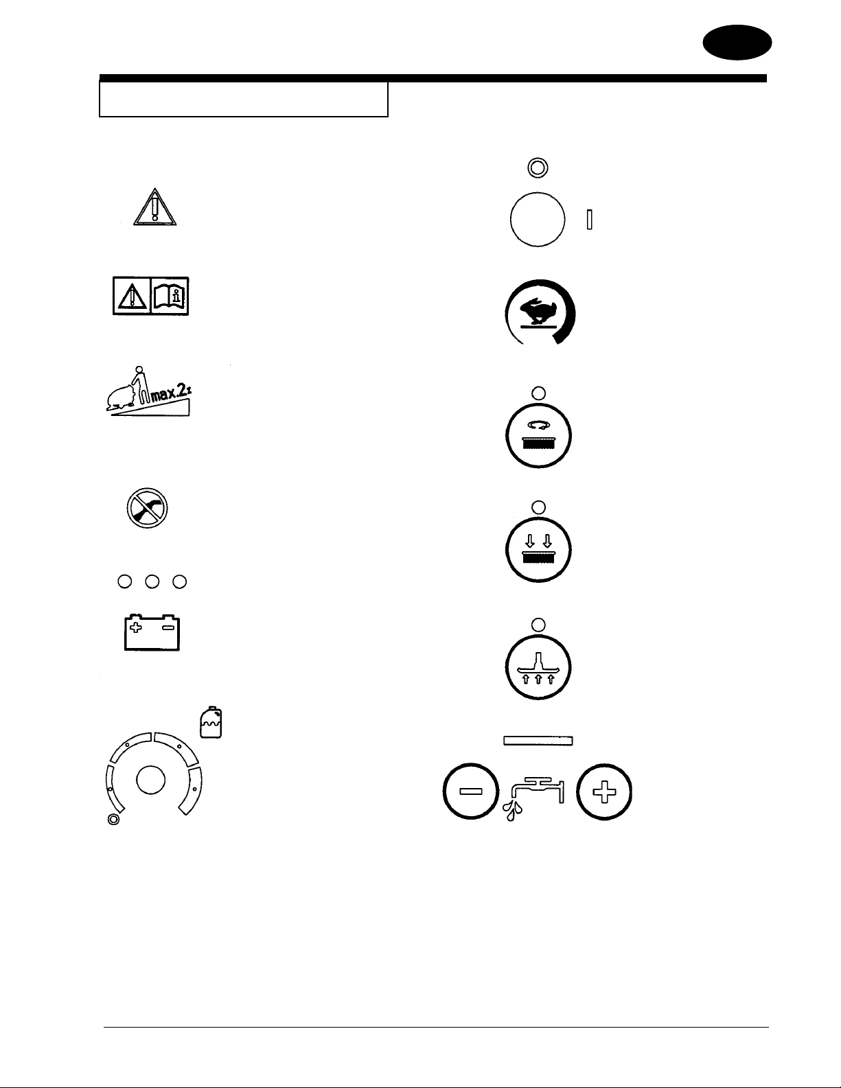
SYMBOLS USED ON SCRUBTEC
ENGLISH
EN
Hazard Alert Symbol
WARNING!
Carefully read all instructions before
performing any procedure.
WARNING!
Do not use the machine on slopes
exceeding the specifi cations.
WARNING!
Do not wash the machine with direct
or pressurized water jets.
On/Off Key Switch
Traverse Speed Control
“One Touch” Control
Additional Brush Pressure
(Not Available on Cylindrical)
Charge/Battery Meter
Chemical Mixing Control
(Optional)
Vacuum On/Off
Solution Control
Nilfi sk ALTO Operator’s Manual (EN) - SCRUBTEC 866, 871, 866, Boost 8 and 871C FORM NO. 71492A - 7 -
Page 8

ENGLISH
EN
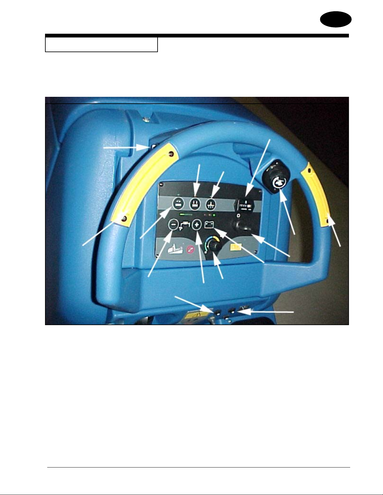
MACHINE CONTROL PANEL
Key Switch (See Figure 1, Item “A”)
The key switch turns “ON” the power to the control panel. “O” is “OFF” and “I” is “ON”.
Traverse Speed Switch (See Figure #1, Item “B”)
The speed control varies from low to high speed. To increase the speed, turn the knob to the right. To decrease the speed, turn the knob to the left.
One Touch Control Button (See Figure 1, Item “C”)
The one touch control button raises and lowers the brush head assembly, starts and stops the vacuum motor automatically. Press the one touch
control button once and the brush head assembly lowers to the fl oor and the vacuum motor turns “ON” (brush head and vacuum LEDs illuminate
green). The brush motors start when the brushes are down and the forward palm button is depressed. Press the one touch control button again and
the brush head assembly raises, the vacuum motor will remain on for 10 seconds and then shut “OFF”.
Increase Brush Pressure Button (See Figure 1, Item D)
This button is used to increase the brush pressure. Increased brush pressure may be required when stripping or cleaning heavily soiled fl oors. T o
increase brush pressure, fi rst lower the brushes by pressing the one touch control button (Item “C”). This will lower the brushes to the normal scrub
position. To increase brush pressure, press the button (Item “D”). The LED above the button will illuminate yellow. Press the button (Item “D”) again
and the brushes will return to normal scrub (yellow LED will turn “OFF”). NOTE: Increase brush pressure is not available on cylindrical machine.
Vacuum Motor Button (See Figure 1, Item “E”)
The vacuum motor button turns the vacuum motor “ON” or “OFF”, regardless of brush head assembly position. The green LED will illuminate when
the vacuum motor is “ON”.
Solution Control Buttons (See Figure 1, Item “F & G”)
The solution control buttons regulate the fl ow of cleaning solution to the fl oor. The normal scrub solution setting is indicated by two green bars on the
meter. On cylindrical machines, with most fl oor conditions, the solution setting should be set one step higher. To increase the fl ow, press the solu-
tion fl ow button “G” (+) until the desired fl ow is reached. To decrease the fl ow, press the solution fl ow button “F” (-) until the desired fl ow is reached.
To shut off the solution, press the solution fl ow button “F” (-) until no indicators are visible on the display. NOTE: No solution will fl ow when the
machine does not traverse.
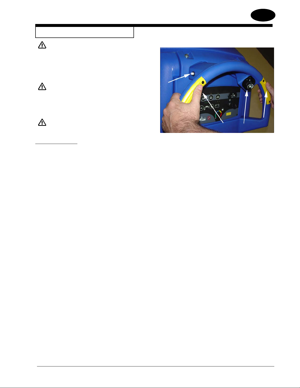
Forward Palm Buttons (See Figure 1, Item “H”)
The forward palm buttons turn the traverse motor “ON” and if the brush motors are in the down position, it also activates the brush motors and solution control module. Either the right or the left palm button can be used.
Reverse Push Button (See Figure 1, Item “I”)
The reverse push button, when used in conjunction with one of the forward palm buttons, causes the machine to reverse direction. The reverse
speed is 67% of the forward speed.
Charge / Battery Meter (See Figure 1, Item “J”)
The charge / battery meter indicates the battery is being charged when the charger is plugged into an AC outlet. It also indicates the amount of
charge that is left in the batteries while the machine is in use. When the charge gets too low the brush/pad motors will shut off.
Circuit Breakers (See Figure 1, Item “K & L”)
The circuit breakers for the brush motors are located on the control panel. If a circuit breaker trips, determine which motor is not operating and turn
the key switch “OFF”. Wait fi ve minutes and push the reset button back in. Turn the key switch “ON”, and try again. An authorized service person
should be contacted if the breaker trips again.
Hour Meter (Optional) (See Figure 1, Item “M”)
The hour meter indicates the number of hours the machine has operated. It runs only when the machine is moving forward or reverse.
Chemical Mixing Control (Optional) (See Figure 1, Item “N”)
The chemical mixing control regulates the amount of concentration of cleaning chemical mixed with the clear water from the solution tank. Turning
the chemical mixing knob clockwise increases the concentration of chemical.
-8- FORM NO. 71492A Nilfi sk ALTO Operator’s Manual (EN) - SCRUBTEC 866, 871, 866, Boost 8 and 871C
Page 9
MACHINE CONTROL PANEL
I
D
E
ENGLISH
M
EN
H
C
F
K
G
Figure 1
N
J
B
A
L
H
Nilfi sk ALTO Operator’s Manual (EN) - SCRUBTEC 866, 871, 866, Boost 8 and 871C FORM NO. 71492A - 9 -
Page 10
ENGLISH
MACHINE CONTROLS AND FEATURES
Squeegee Lift Handle (Manual Squeegee Lift) (See fi gure 2)
The squeegee lift handle is located below the control handles in the center. It is
used to raise or lower the squeegee.
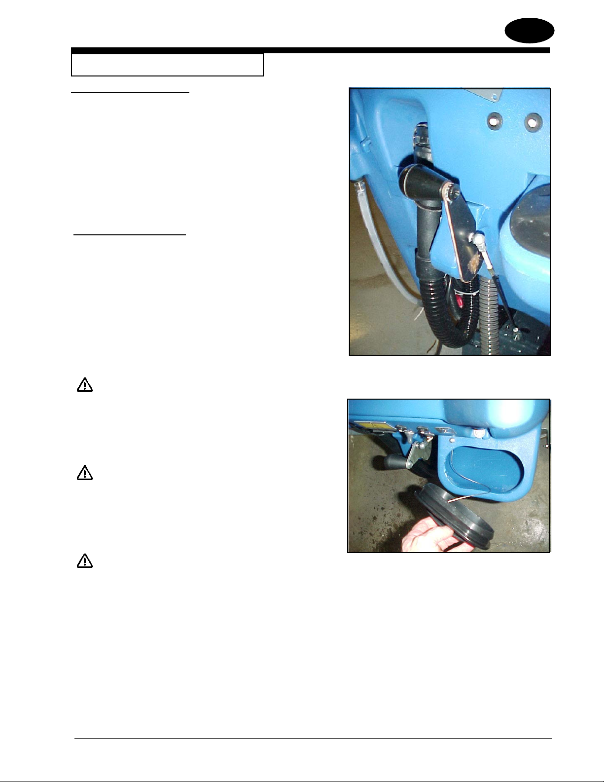
Float Shut Off (See Figure 3).
The shut-off switch for the vac motor is located in the recovery tank. It automatically turns off the vac motor when the recovery tank is full.
EN
HOW TO PREPARE THE MACHINE
FOR OPERATION
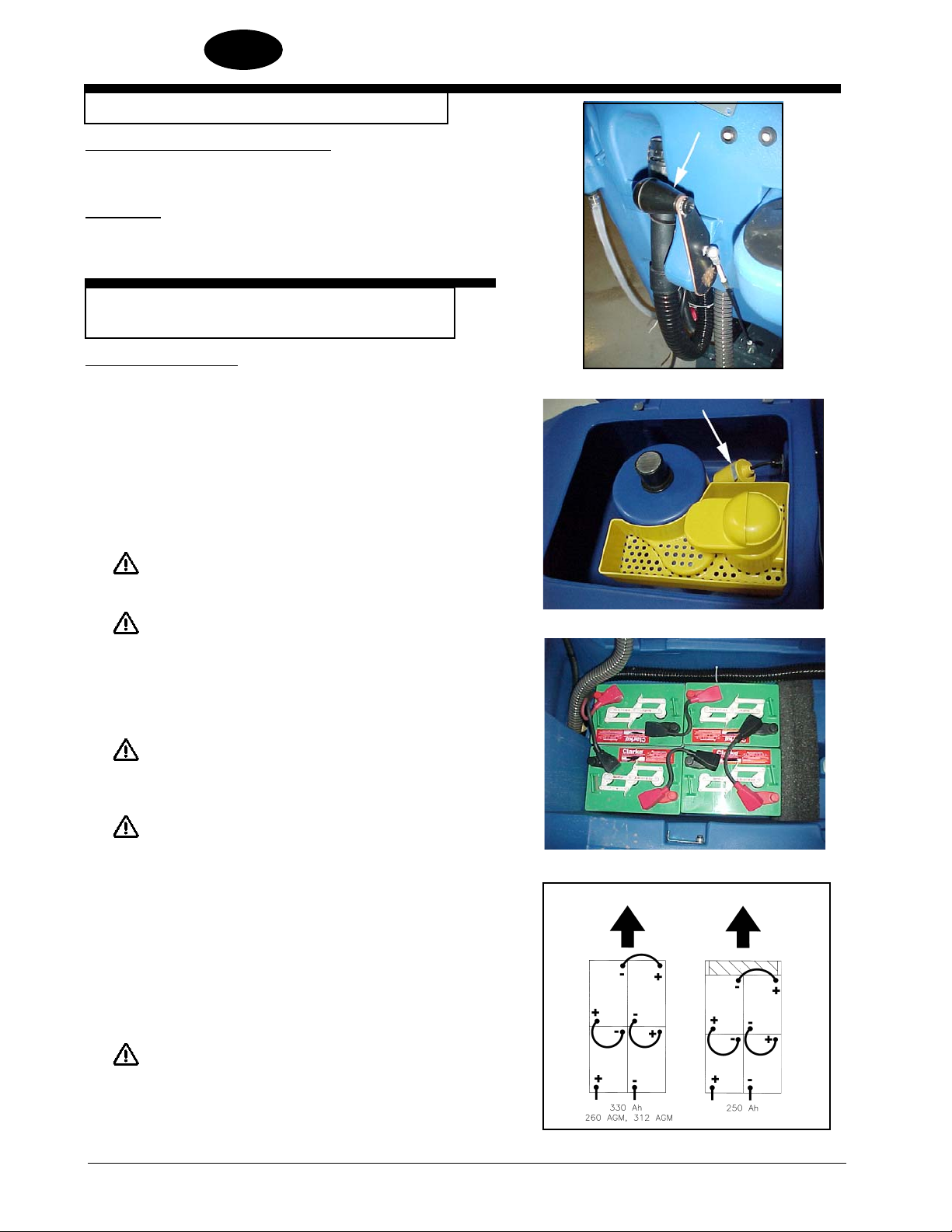
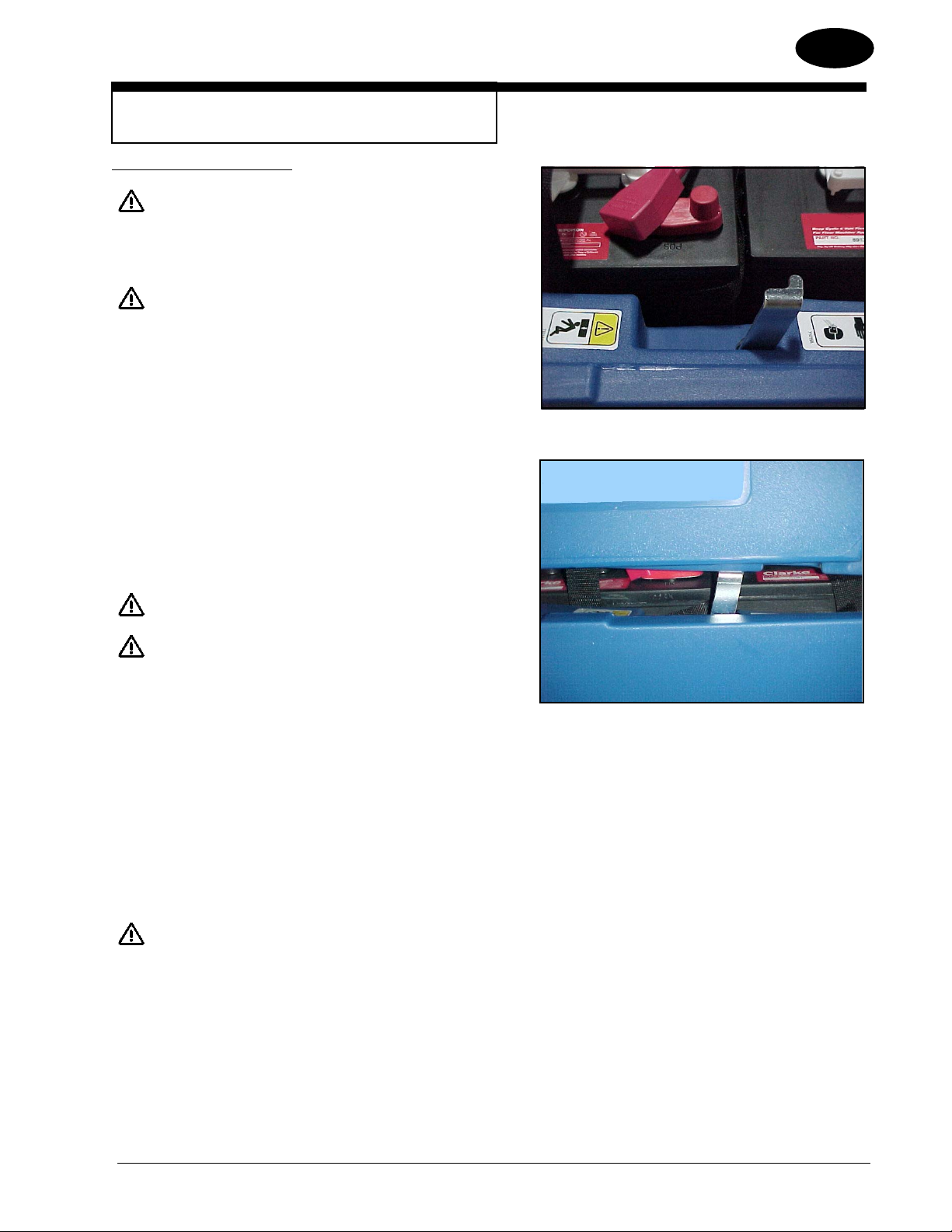
How To Install The Batteries
This machine uses four - 6 volt batteries. The batteries are located in the battery
compartment under the recovery tank.
To install the batteries, follow this procedure:
1. Turn machine off. Set brake (if equipped).
2. Make sure recovery tank is empty.
Figure 2
3. Tip up the recovery tank to it’s full open position. See
fi gure 4.
4. Place the batteries in the tray as shown in Figure 5.
5. Connect the cables between batteries and install battery cable assembly
CAUTION: Before raising the tank, be sure tank is
empty.
WARNING: Do not operate the machine while the
recovery tank is in the open position. The
tank can be accidentally bumped and it may
slam shut.
WARNING: The batteries are heavy. Lifting batteries
without help could result in an injury. Get
help to lift the batteries.
WARNING: Working with batteries can be dangerous.
Always wear eye protection and protective
clothing when working near batteries. NO
SMOKING!
as indicated. See fi gure 5.
Figure 3
Figure 4
FRONT
6. Join the connector from the battery pack to the connector on the control
panel.
7. Close recovery tank by slowly lowering the tank.
WARNING: Never charge any battery with an unsuitable
battery charger. Carefully follow the instructions by the manufacturer of the batteries
and battery charger.
Figure 5
-10- FORM NO. 71492A Nilfi sk ALTO Operator’s Manual (EN) - SCRUBTEC 866, 871, 866, Boost 8 and 871C
revised 9/10
Page 11
HOW TO PREPARE THE MACHINE
FOR OPERATION
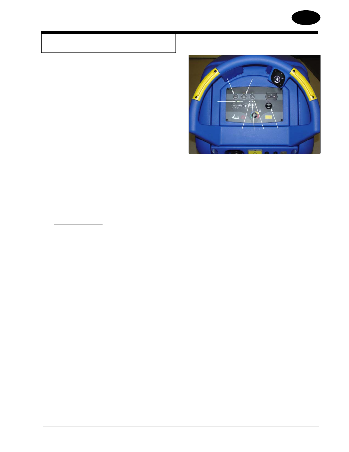
How to program battery charger (WET or AGM batteries):
According to the type of batteries (WET or AGM), set the machine and
electronic board of the battery charger as follows:
Charger Setting
1. Turn the key switch “ON” (see fi gure 5A, item A) and in the very
fi rst seconds of machine operation pay attention to the following:
• If the green warning light (item B) is fl ashing, the charger is
set to AGM.
• If the yellow warning light (item C) is fl ashing, the charger is
set to GEL EXIDE.
• If the red warning light (item D) is fl ashing, the charger is set
to WET.
G
E
ENGLISH
F
DCB
EN
A
2. If the setting is to be changed, perform the following procedure:
a. Turn the key switch “OFF”.
b. Press and hold the buttons (items E and F) at the same time,
then turn the key switch (item A) “ON”.
c. Continue to hold the buttons (items E and F) until the battery
meter LED light turns “ON” and “OFF” and then release both
buttons.
d. Within 3 seconds, toggle the button (item F) to advance the
green bar (item G) to the desired charger setting (see green
bar position for charger settings below):
Green bar setting (item G)
• 1st green bar - WET @ 25 amps, 250 & 330 ah batteries
(4 RED blinks).
• 2nd green bar - GEL/AGM @ 25 amps, 260 & 312 AGM (4
GREEN blinks).
• 3rd green bar - GEL EXIDE @ 25 amps (4 YELLOW
blinks).
• 4th green bar - WET @ 15 amps (2 RED blinks).
• 5th green bar - GEL/AGM @ 15 amps (2 GREEN blinks).
• 6th green bar - GEL EXIDE @ 15 amps (2 YELLOW
blinks).
e. Once proper battery charger profi le is selected, wait until bat-
tery LED light quits fl ashing and stays on before turning key
switch “OFF”.
f. Repeat step 1 to verify that proper charger profi le was pro-
grammed for battery type (WET or GEL).
Figure 5A
NOTE: Charge the batteries before using the
machine.
Nilfi sk ALTO Operator’s Manual (EN) - SCRUBTEC 866, 871, 866, Boost 8 and 871C FORM NO. 71492A - 11 -
Page 12
ENGLISH
EN
HOW TO PREPARE THE MACHINE
FOR OPERATION
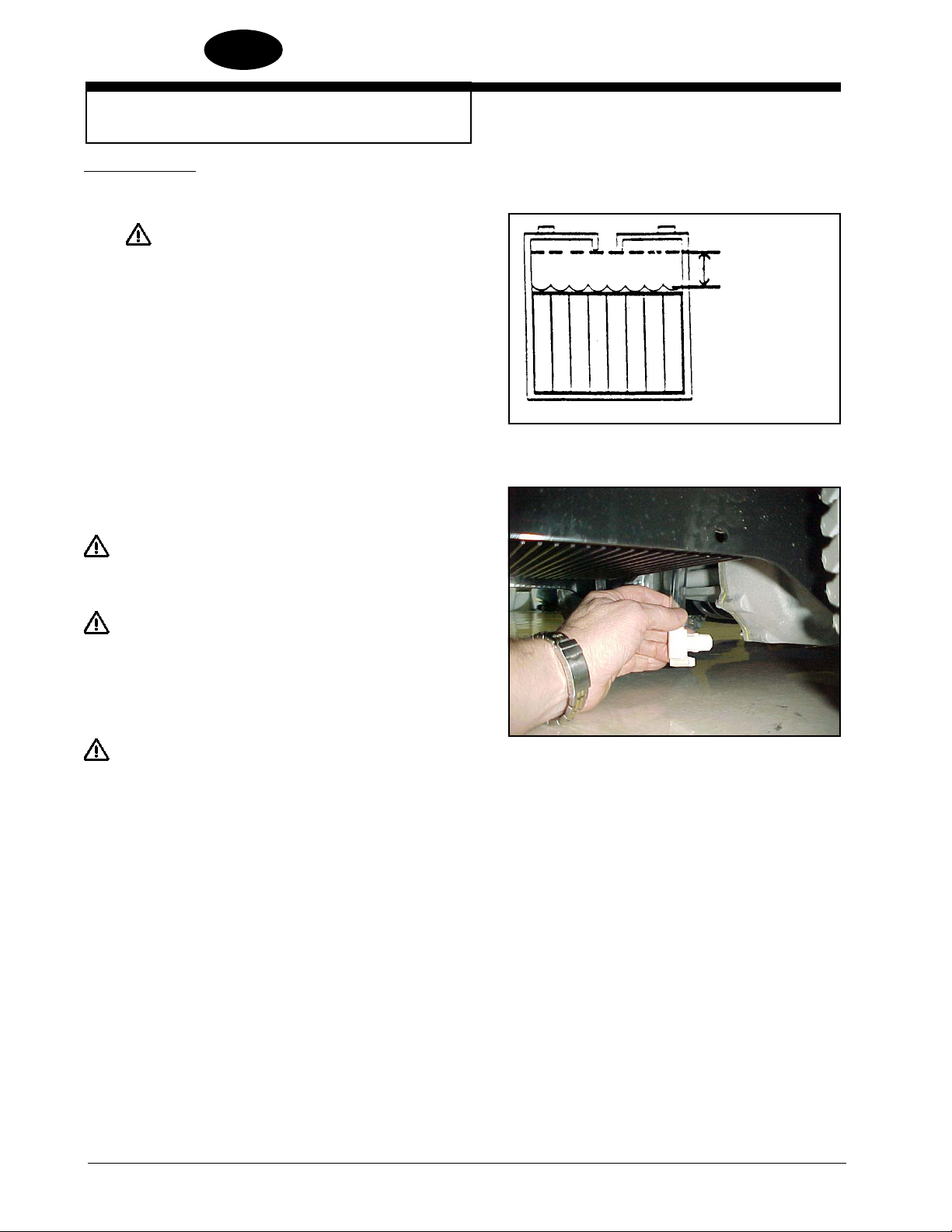
Battery Maintenance
The electrical power to operate the machine comes from the storage batteries.
Storage batteries need preventative maintenance.
WARNING: Working with batteries can be dangerous.
Always wear eye protection and protective
clothing when working near batteries. NO
SMOKING!
To maintain the batteries in good condition, follow these instructions:
1. Keep the electrolyte at the correct level. The correct level is between 1/4”
(1/2 cm) below the bottom of the tube in each cell and above the tops of
the plates. Check the level of the electrolyte each time you charge the
batteries. See fi gure 6.
Correct Level
NOTE: Check the level of electrolyte prior to charging the batteries. Be sure the
plates in each cell are covered with electrolyte before charging. Do not top off
the cells prior to charging the battery. Electrolyte expands during charging. As a
result, the electrolyte could overfl ow from the cells. Always top off the cells with
distilled water after charging.
CAUTION: Irreversible damage will occur to the batteries if
electrolyte does not cover the plates. Keep the
electrolyte at the correct level.
CAUTION: Machine damage and discharge across the tops of
the batteries can occur if the batteries are over fi lled.
Do not fi ll the batteries up to the bottom of the tube
in each cell. Wipe any acid from the machine or the
tops of the batteries. Never add acid to a battery after
installation.
CAUTION: Batteries must be refi lled with distilled water only. Do
not use tap water as it may contain contaminants that
will damage batteries.
2. Keep the tops of the batteries clean and dry. Keep the terminals and
connectors clean. To clean the top of the batteries, use a damp cloth with
a weak solution of ammonia or bicarbonate of soda solution. To clean the
terminals and connectors, use a terminal and connector cleaning tool. Do
not allow ammonia or bicarbonate of soda to get into batteries.
Figure 6
Figure 7
3. Keep the batteries charged.
4. To drain battery compartment: (See fi gure 7)
a. Always wear protective eye protection and protective clothing.
b. Add a weak solution of ammonia or bicarbonate of soda solution to
battery compartment to neutralize any spilled acid.
c. Locate drain hose behind the transaxle.
d. Place hand behind fl ange and open valve.
e. When empty, close valve.
f. Neutralize any acid spills with ammonia or bicarbonate of soda.
-12- FORM NO. 71492A Nilfi sk ALTO Operator’s Manual (EN) - SCRUBTEC 866, 871, 866, Boost 8 and 871C
Page 13
HOW TO PREPARE THE MACHINE
FOR OPERATION
How To Charge The Batteries
WARNING: Charging the batteries in an area without ade-
quate ventilation could result in an explosion.
To prevent an explosion, charge the batteries
only in an area with good ventilation.
WARNING: Lead acid batteries generate gases which
could explode. Keep sparks and fl ames away
from batteries. NO SMOKING!
To charge the batteries, follow this procedure:
ENGLISH
EN
1. Make sure the key switch is in the “OFF” position.
2. Before charging the batteries, the battery compartment needs to
be vented. To vent compartment, tip up the recovery tank and
rotate the tank support bracket, located in the solution tank (see
fi gure 8). Slowly lower the recovery tank and let it rest on the support bracket (see fi gure 9). To close the tank, lift up on the recovery
tank, rotate the support bracket down, then slowly lower the tank to
the closed position.
CAUTION: Before raising tank, be sure tank is empty.
W ARNING: Do not operate the machine while the recovery
tank is in the open position. The tank can be
accidentally bumped and it may slam shut.
3. Connect the battery charger AC cord located at the rear of the machine to an appropriate wall receptacle.
4. Observe indicator lights on the charger/battery meter to ensure the
charging process has started. Red, yellow and green lights indicate state of charge. Steady on green light indicates the batteries
are fully charged.
Figure 8
Figure 9
NOTE: Make sure you plug into a circuit that is not loaded by other equipment. Wall breakers may be tripped and no charge will occur.
WARNING: Never charge any battery with an unsuitable
battery charger. Carefully follow the instructions given by the manufacturer of the batteries and battery charger.
NOTE: To prevent permanent damage to the batteries, avoid their complete discharge. Never leave the batteries completely discharged, even if
the machine is not being used. When recharging the batteries, keep the
recovery tank open. Check the level of the electrolyte and if necessary
top off with distilled water.
Nilfi sk ALTO Operator’s Manual (EN) - SCRUBTEC 866, 871, 866, Boost 8 and 871C FORM NO. 71492A - 13 -
revised 9/10
Page 14
ENGLISH
EN
HOW TO PREPARE THE MACHINE
FOR OPERATION
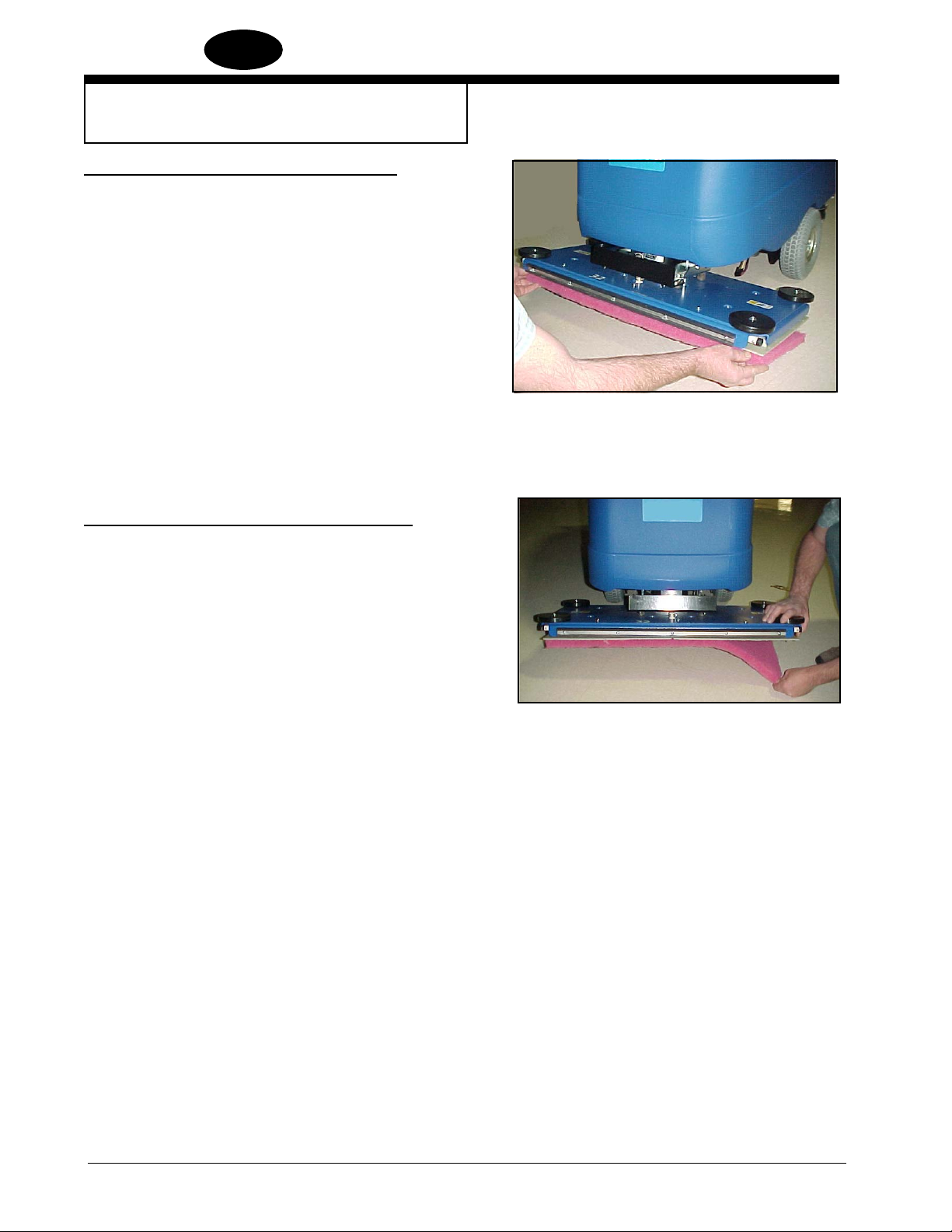
How To Install The Brush Or Pad (BOOST Machine)
To install the brush or pad on the machine, follow this
procedure:
1. Turn the key switch “ON”.
2. Put the brush head assembly in the “Up” position.
3. Turn the key switch “OFF”.
4. Go to the front of the machine.
5. Press on a brush or pad, under the fl ex plates.
See fi gure 10.
NOTE: When using a black pad, position pad on head. Lower head
and operate momentarily to affi x pad to pad driver (if you have
diffi culty, position pad on fl oor and lower head then operate.)
How To Remove The Brush Or Pad (BOOST Machine)
To remove the brush or pad from the machine, follow this procedure:
1. Turn the key switch “ON”.
2. Put the brush head assembly in the “Up” position.
3. Turn the key switch “OFF”.
4. Go to the front of the machine and pull downward on the brush or
pad until it releases from the fl ex plates. See fi gure 11.
Figure 10
Figure 11
-14- FORM NO. 71492A Nilfi sk ALTO Operator’s Manual (EN) - SCRUBTEC 866, 871, 866, Boost 8 and 871C
Page 15
HOW TO PREPARE THE MACHINE
FOR OPERATION
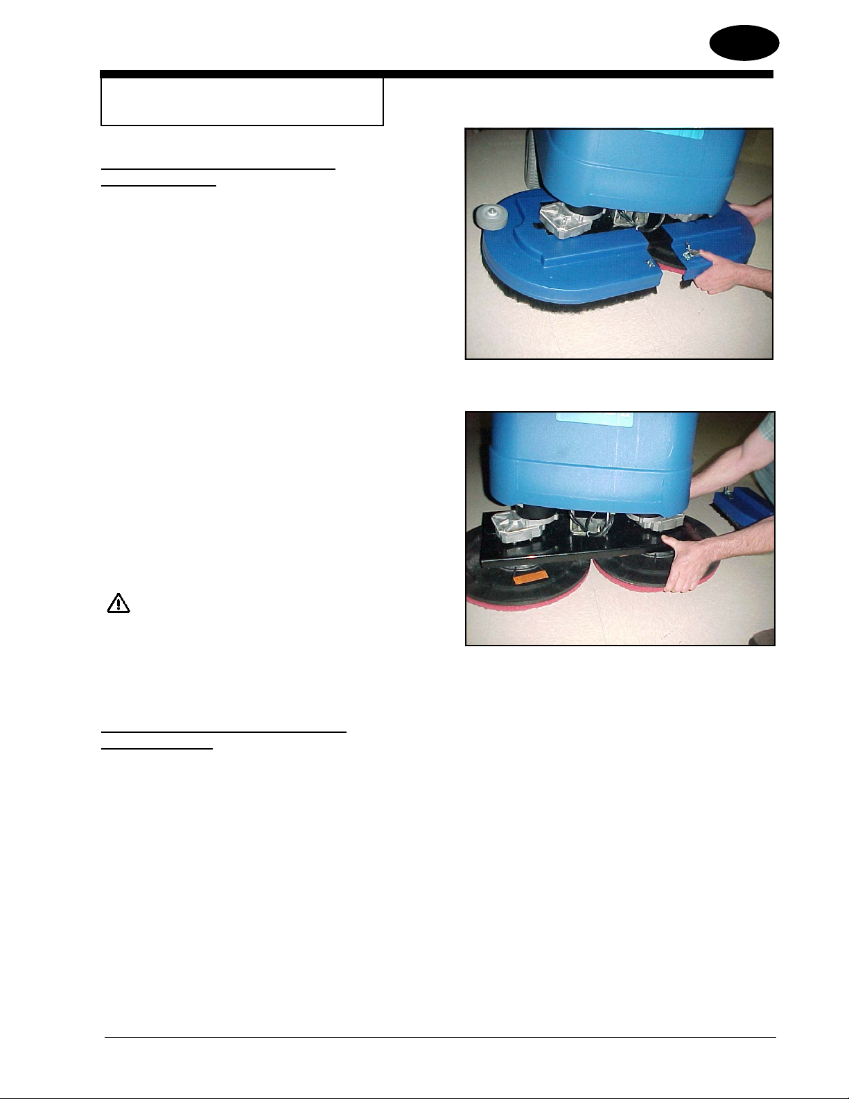
How To Install The Brushes Or Pad Drivers
On The Disc Machine
To install the brushes or pad drivers on the machine,
follow this procedure:
1. Turn the key switch “ON”.
2. Put the brush head assembly in the “UP” position.
3. Turn the key switch “OFF”.
4. Unlatch right and left brush housings and remove them. See
fi gure 12.
5. Put a brush or pad driver under the brush motor plate. See
fi gure 13.
6. Align the lugs on the motor gimbal with the slots in the brush
gimbal.
ENGLISH
Figure 12
EN
7. Pull the brush up until the gimbal locks.
8. Repeat steps 5, 6 and 7 to install the second brush or pad driver.
9. Reinstall right and left brush housings and latch front cover.
DANGER: Operating a machine that is not completely
or fully assembled could result in injury or
property damage. Do not operate this machine unless it is completely assembled.
Inspect the machine carefully before operation.
How To Remove The Brushes Or Pad Drivers
On the Disc Machine
To remove the brushes or pad drivers from the machine, follow this
procedure:
1. Turn the key switch “ON”.
2. Put the brush head assembly in the “UP” position.
3. Turn the key switch “OFF”.
Figure 13
4. Unlatch right and left brush housings and remove them. See
fi gure 12.
5. Push down on two sides of the brush or pad driver until the gimbals release.
Nilfi sk ALTO Operator’s Manual (EN) - SCRUBTEC 866, 871, 866, Boost 8 and 871C FORM NO. 71492A - 15 -
Page 16
ENGLISH
EN
HOW TO PREPARE THE MACHINE
FOR OPERATION
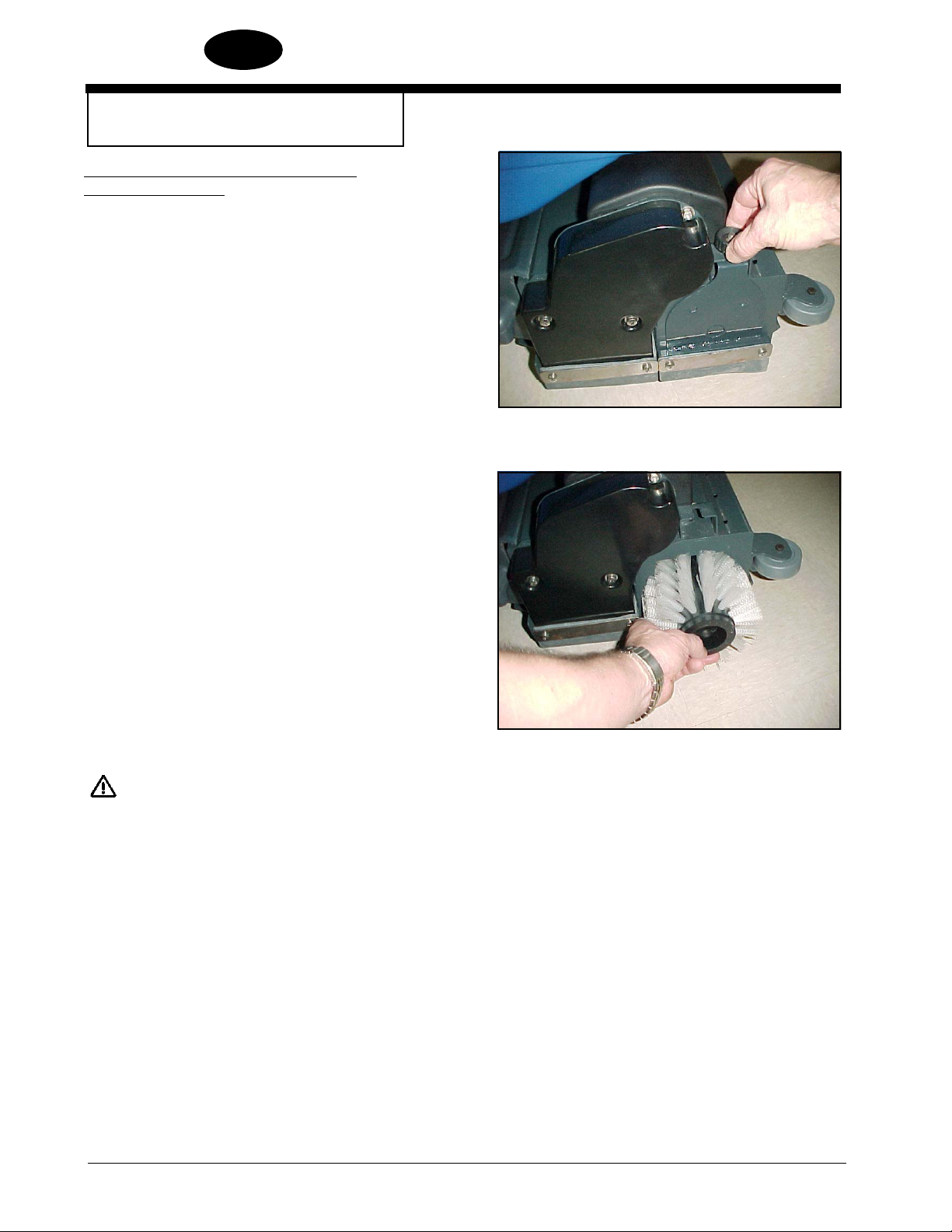
How To Change Or Reverse Bristle Direction
On Cylindrical Machine
To install or reverse bristle direction on the machine, follow this
procedure:
1. Turn the key switch “ON”.
2. Put the brush head assembly in the “UP” position.
3. Turn the key switch “OFF”.
4. Go to the front of the machine and loosen thumb screw on
brush door. See fi gure 14.
5. Lower door approximately 1/2 inch and remove brush door.
6. Remove brush. See fi gure 15.
Figure 14
7. Inspect brush condition. If damaged or worn, replace it. Otherwise, turn brush end for end periodically to reverse bristle
direction for better life.
8. Slide brush onto driver or opposite side and rotate slowly until drive lugs are lined up with brush slots. Push brush all the
way in.
9. Install brush door assembly into brush.
10. Raise door and tighten thumb screw.
11 Repeat for the other brush.
DANGER: Operating a machine that is not com-
pletely or fully assembled could result
in injury or property damage. Do not
operate this machine unless it is completely assembled. Inspect the machine
carefully before operation.
Figure 15
-16- FORM NO. 71492A Nilfi sk ALTO Operator’s Manual (EN) - SCRUBTEC 866, 871, 866, Boost 8 and 871C
Page 17
HOW TO OPERATE THE MACHINE
How To Operate the Squeegee
The squeegee wipes the fl oor while the vacuum motor removes the
dirty solution from the fl oor. Use your hand to lower or raise the
squeegee handle. To operate the squeegee, follow this procedure:
1. To lower the squeegee rotate the squeegee lever down. See
fi gure 16.
2. To raise the squeegee, rotate the squeegee lever up. See
fi gure 16.
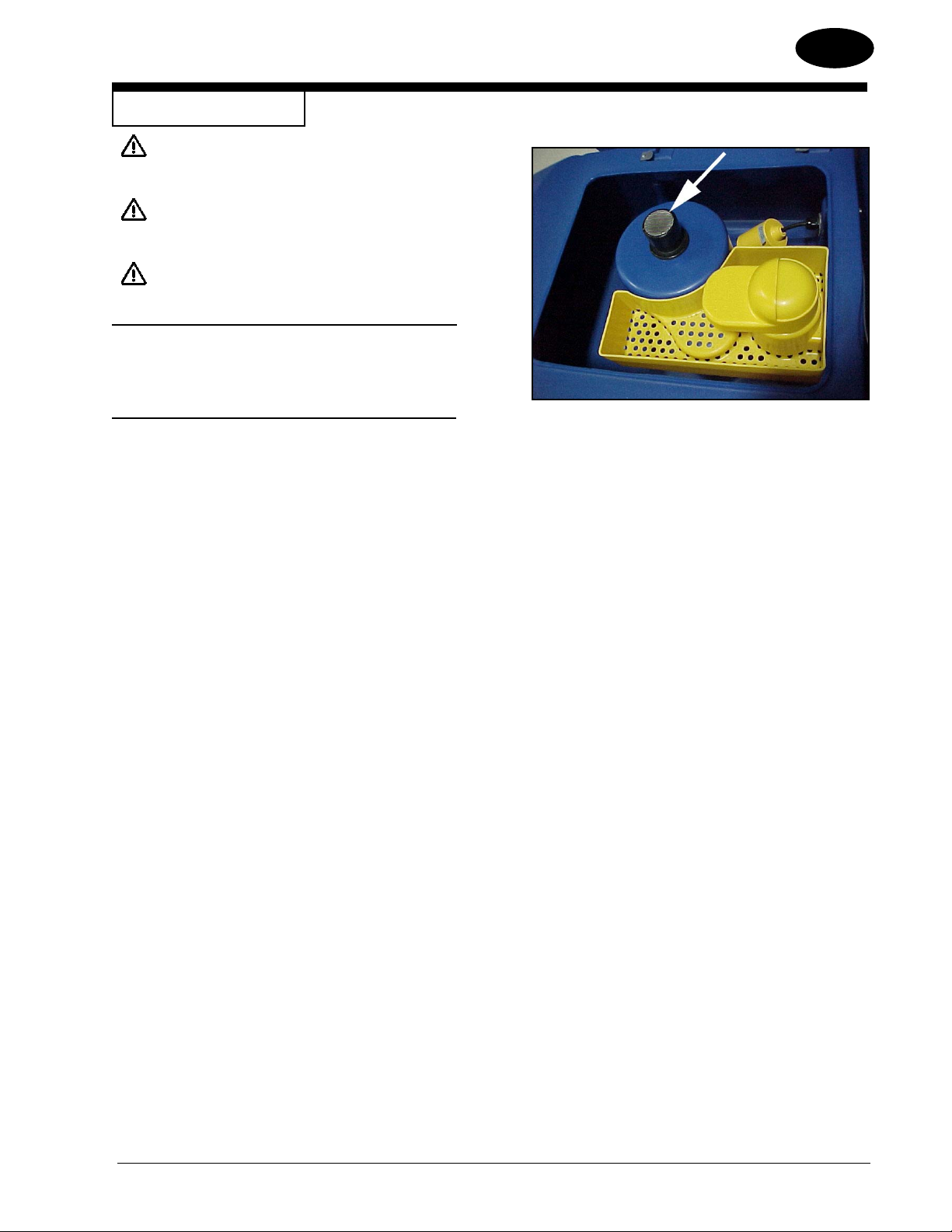
How to Fill The Solution Tank
1. Remove the solution tank lid. See fi gure 17.
2. If the machine does not have the Chemical Mixing System,
add a cleaning chemical to the solution tank. For the correct amount of chemical, follow the directions shown on the
container.
ENGLISH
EN
3. Fill the solution tank with water.
4. Replace solution tank lid.
WARNING: Water solutions or cleaning materials used
with this type of machine can leave wet areas on the fl oor surface. These areas can
cause a dangerous condition for the operator or other persons. Always put CAUTION
signs near the area you are cleaning.
WARNING: Machines can ignite fl ammable materi-
als and vapors. Do not use with or near
fl ammables such as gasoline, grain dust,
solvents, and thinners. Only use a cleaning concentration recommended by the
chemical manufacturer.
WARNING: Nilfi sk ALTO recommends a maximum
water temperature of 120°F(49°C)
Figure 16
Figure 17
Nilfi sk ALTO Operator’s Manual (EN) - SCRUBTEC 866, 871, 866, Boost 8 and 871C FORM NO. 71492A - 17 -
Page 18

ENGLISH
EN
HOW TO OPERATE THE MACHINE
How To Operate The Chemical Mixing System (Optional)
The chemical mixing system is designed to automatically mix the
cleaning chemical directly from the manufacturer’s chemical container into the clear water coming from the solution tank. The chemical
control knob on the control panel is used to select the desired ratio
according to the recommendation of the chemical manufacturer and
the application requirements. The ratio settings are shown in fi gure
19.
CAUTION: Do not operate the chemical pump dry.
If the chemical container is empty, make
sure the chemical control is in the off
position.
To operate the chemical mixing system, follow this procedure:
1. Select the proper cleaning chemical for scrubbing application.
Figure 18A
2. Set the chemical knob to the recommended setting per the
chemical manufacturer.
3. Make sure the recovery tank is empty and then open the
recovery tank.
4. Position the manufacturer’s chemical container into the
bracket located at the front right side of the solution tank.
See fi gure 18A & 18B
5. Remove container cap and insert bottle adapter and
tighten cap.
6. Slowly close the recovery tank.
NOTE: With the knob turned fully counterclockwise, only
water will be delivered to the fl oor.
Figure 18B
GREEN
BLUE
YELLOW
RED
Figure 19
-18- FORM NO. 71492A Nilfi sk ALTO Operator’s Manual (EN) - SCRUBTEC 866, 871, 866, Boost 8 and 871C
Page 19
HOW TO OPERATE THE MACHINE
WARNING: Water solutions or cleaning materials used with
this type of machine can leave wet areas on the
fl oor surface. These areas can cause a dangerous condition for the operator or other persons.
Always put CAUTION signs near the area you
are cleaning.
WARNING: Machines can ignite fl ammable materials and
vapors. Do not use with or near fl ammables
such as gasoline, grain dust, solvents and
thinners. Only use a cleaning concentration
recommended by the chemical manufacturer.
B
ENGLISH
EN
WARNING: Nilfi sk ALTO recommends a maximum water
temperature of 120oF (49oC).
Operating The Machine
NOTE: Put the machine in the lowest traverse speed setting. Use the
machine in an area that has no furniture or objects until you can do the
following:
1. Move the machine in a straight direction, forward and backward.
2. Stop the machine safely.
3. Turn the machine both left and right and return to a straight direction.
To move the machine, follow this procedure:
1. Release the parking brake (if equipped with machine).
2. Turn the key switch to the “ON” position
3. Raise the brush.
4. Raise the squeegee.
Figure 20
A
A
C
5. When either the left or right forward palm buttons (fi gure 20, item A)
are pushed in, the machine will go forward.
6. Control the speed of traverse by using the traverse speed control
knob (fi gure 20, item C).
7. To stop, release the forward palm buttons.
8. To reverse the machine, push in the white reverse switch (fi gure 20
item B) and either the right or left forward palm buttons (fi gure 20
item A) at the same time.
9. To stop, release the forward palm buttons.
10. To turn the machine, push the rear of the machine to the side.
11. When you stop the machine, turn the key switch “OFF”, remove the
key and set the parking brake (if equipped).
Nilfi sk ALTO Operator’s Manual (EN) - SCRUBTEC 866, 871, 866, Boost 8 and 871C FORM NO. 71492A - 19 -
Page 20

ENGLISH
EN
HOW TO OPERATE THE MACHINE
How To Clean A Floor
WARNING: Water solutions or cleaning materials used with
this type of machine can leave wet areas on the
fl oor surfaces. These areas can cause a dangerous
condition for the operator or other persons. Always
put CAUTION signs near the area you are cleaning.
To clean a fl oor, follow this procedure:
1. Set the parking brake (if equipped with machine.)
2. Put the water and a cleaning chemical in the clean solution tank.
3. Release the parking brake (if equipped with machine.)
4. Turn the key switch “ON”.
5. Lower the squeegee.
6. Press the one touch control button to lower the brush head assembly
and start vacuum motor.
7. Adjust the fl ow of clean solution to the fl ow desired.
8. Move the machine across the fl oor in the forward direction.
9. Make a 180° turn.
NOTE: When you make more passes across the fl oor, let the brush clean
approximately 2 inches (5 cm) of the area already cleaned by the brush.
NOTE: During most cleaning procedures, apply and remove the solution in
one operation.
How To Clean A Very Dirty Floor
To clean a very dirty fl oor, follow this procedure:
1. Apply solution to the fl oor.
2. Do not lower the squeegee. Shut vacuum motor “OFF”.
3. Lower the brush or pad and scrub the fl oor.
4. Scrub the fl oor again with additional solution and lower the squeegee
and turn vacuum motor “ON”.
5. Pick up all the solution with the squeegee.
-20- FORM NO. 71492A Nilfi sk ALTO Operator’s Manual (EN) - SCRUBTEC 866, 871, 866, Boost 8 and 871C
Page 21
MAINTENANCE
WARNING: Maintenance and repairs must be done by au-
thorized personnel only.
WARNING: Always empty the solution tank and recovery
tank before doing any maintenance.
WARNING: Keep all fasteners tight.
These Maintenance Procedures Must Be Done Every Day
Keep the machine clean, it will need fewer repairs and have longer
life.
ENGLISH
EN
Do These Procedures When You Begin Your Work Period
1. Turn off key switch.
2. Disconnect AC power from battery charger (follow charger instructions).
3. Make sure the screen fi lter over the vacuum motor is clean and
in position (see fi gure 21.
4. Make sure the valve on the recovery drain hose is clean. Tightly
close the valve.
5. Make sure the brushes are in position and installed correctly
6. Check the installation of the squeegee and squeegee hose.
7. Make sure the solution drain/level indicator hose is secure on
upper fi tting.
Figure 21
Nilfi sk ALTO Operator’s Manual (EN) - SCRUBTEC 866, 871, 866, Boost 8 and 871C FORM NO. 71492A - 21 -
Page 22

ENGLISH
EN
MAINTENANCE
Do These Procedures When You End Your Work
1. Drain the solution tank (if necessary) (Figure 22) and the recovery
tank (Figure 23). To drain the tanks, follow this procedure:
a. Turn the key switch “OFF”.
b. Remove the drain hose from the back of the machine.
c. Put the end of the hose over a drain or bucket.
d. Recovery Tank:
Turn the drain cap counterclockwise to open.
Solution Tank:
When hose is lowered to water level, water will fl ow.
2. Flush the tanks. To fl ush the tanks, put clean water in the tank
through the opening on top of the tank.
Figure 22
3. If a tank or drain hose has an obstruction, use a water hose to fl ush
the tank or hose. Put the water hose into the drain hose.
4. Leave the tanks and the recovery drain valve open to dry in the air.
5. Check the squeegee blade. Use a cloth to clean the squeegee
blade. If the squeegee blade is damaged or worn, turn or replace
the blade.
6. Check and clean the solution lid gasket. Use a mild cleaning solu-
tion and rinse the parts in clean water.
Check the batteries and if necessary add distilled water after charging.
The correct level is within 1/4 inch (1/2 cm) of the bottom of the tube
in each cell.
CAUTION: Tap water may contain contaminants that
will damage batteries. Batteries must be
refi lled with DISTILLED WATER ONLY.
WARNING: Lead acid batteries generate gases which
can cause an explosion. NO SMOKING.
Always wear eye protection and protective clothing when working near batteries.
Figure 23
Use a clean cloth and wipe the surface of the machine.
Charge the batteries. See the instruction in the section of this book
called “How To Charge The Batteries”.
-22- FORM NO. 71492A Nilfi sk ALTO Operator’s Manual (EN) - SCRUBTEC 866, 871, 866, Boost 8 and 871C
Page 23

MAINTENANCE
These Maintenance Procedures Must Be Done Every Week:
WARNING: Maintenance and repairs must be done by authorized
personnel only. Always empty the solution tank and
the recovery tank before doing any maintenance.
Keep all fasteners tight.
WARNING: Always wear eye protection and protective clothing
when working near batteries. Do not put tools or other
metal objects across the battery terminals or the tops
of the batteries.
CAUTION: To prevent damage to the machine, and discharge
across the tops of the batteries, do not fi ll the batteries
above the bottom of the tube in each cell. Wipe any
acid from the machine or the tops of the batteries. Do
not add acid to battery after installation.
NOTE: Always turn off key switch before servicing the machine.
ENGLISH
Figure 24
EN
WARNING: Always wear eye protection and protective clothing
when working near batteries. NO SMOKING!
1. To inspect batteries, tip up recovery tank to its full open position. See fi gure
24. To close the tank, slowly lower the tank to the closed position.
CAUTION: Before raising the tank, be sure tank is empty.
WARNING: Do not operate the machine while the recovery tank
is in the open position. The tank can be accidentally
bumped and it may slam shut.
2. Disconnect the batteries. Use a cloth and a solution of ammonia or bicarbonate of soda to wipe the top of the batteries. Clean the battery terminals.
Reconnect the batteries.
3. Check the hoses for leaks, obstructions and other damage.
Nilfi sk ALTO Operator’s Manual (EN) - SCRUBTEC 866, 871, 866, Boost 8 and 871C FORM NO. 71492A - 23 -
Page 24

ENGLISH
EN
MAINTENANCE
Maintenance For The Squeegee
To remove the squeegee, follow this procedure:
1. Remove the squeegee assembly by loosening the two knobs that attach
the squeegee to the machine. Pull the squeegee assembly off. See
fi gure 25.
2. Inspect the squeegee blades.
3. If the blades are worn, unclamp bands and turn the blade so that a new
edge is in the wiping position (see fi gures 25A and 25B).
4. Reinstall squeegee assembly on the machine.
Adjusting Squeegee Tilt
The tilt of the squeegee causes the rear blade to raise up in the center or
on the ends, depending on which direction the tilt is changed. Turn
the adjusting screw clockwise or counterclockwise (see fi gure 26), to
achieve uniform squeegee blade fl are.
WARNING: Maintenance and repairs must be done by au-
thorized personnel only.
WARNING: Electrical repairs must be done by authorized
personnel only.
Maintenance Procedures Must Be Done :
Contact a Nilfi sk ALTO Authorized Service Center
to perform these procedures.
Every 500 hrs (heavy) 1000 hrs (normal)
Figure 25
Figure 25A
1. Check the carbon brushes in the electric motors.
2. Clean the battery terminals and connectors. Make sure all of the battery connections are tightened correctly.
Figure 25B
3. Check all of the switches, controls, valves, hoses and gaskets.
4. Check and remove debris from the transaxle hubs.
Every 500 hrs (BOOST Only)
1. Replace the rubber isolators (see Brush Head Assembly Parts List section). The rubber isolators are considered wear items and must be replaced between 500 hrs (heavy) and 1000 hrs (normal).
Figure 26
-24- FORM NO. 71492A Nilfi sk ALTO Operator’s Manual (EN) - SCRUBTEC 866, 871, 866, Boost 8 and 871C
revised 9/10
Page 25

PROBLEM CAUSE ACTION
The machine does not remove all the
water from the fl oor.
HOW TO CORRECT PROBLEMS IN THE MACHINE
The squeegee is up
The vacuum tank is full.
Lower the squeegee.
Drain the tank.
ENGLISH
EN
The batteries do not give the normal
running time.
The cleaning is not even.
The screen fi lter is dirty.
There is an obstruction or damage in the
squeegee, squeegee hose or standpipe.
The vacuum motor is not running.
The squeegee hose is disconnected.
The squeegee blade is damaged, worn, or in-
correctly installed.
The gasket on the cover of the recovery tank
is damaged.
The recovery drain hose valve is not
closed.
The battery terminals are dirty or damaged.
The electrolyte level is too low.
The batteries are not fully charged.
The charger is damaged.
The battery is defective.
The batteries are disconnected.
The scrub brushes or pads are worn.
There is damage to the brush assembly, cast-
ers or the solution valve.
Clean the screen fi lter.
Remove the obstruction or repair the damage.
Check for blown fuse. Have an authorized service person make repairs.
Connect the hose.
Turn or replace the squeegee blade.
Correctly install the squeegee blade.
Replace the gasket.
Close valve.
Clean the terminals and connectors. Replace
the damaged cables. Charge the batteries.
Add distilled water to each cell and charge the batteries.
Charge the batteries for a full 16 hour charge.
Have an authorized service person repair the charger.
Have an authorized service person check voltage of
each cell while discharging.
Connect the batteries.
Replace the scrub brushes or pads.
Have an authorized service person make the needed
repairs.
The machine does not run.
One or both brush motors are not running
The solution level is low.
The machine loses power.
Check for tripped breaker, reset. Check for loose
connections.
Fill the solution tank.
NOTE: If the motors continue to stop consult an autho-
rized service person.
Reset the circuit breaker.
Check wire connection to traverse motor.
Replace the fuses.
Check the batteries connections.
Release parking brake (if installed)
NOTE: If the motors continue to stop, consult an au-
thorized service person.
Nilfi sk ALTO Operator’s Manual (EN) - SCRUBTEC 866, 871, 866, Boost 8 and 871C FORM NO. 71492A - 25 -
Page 26

ENGLISH
EN
-26- FORM NO. 71492A Nilfi sk ALTO Operator’s Manual (EN) - SCRUBTEC 866, 871, 866, Boost 8 and 871C
Page 27

ENGLISH
EN
Nilfi sk ALTO Operator’s Manual (EN) - SCRUBTEC 866, 871, 866, Boost 8 and 871C FORM NO. 71492A - 27 -
Page 28

ENGLISH
EN
NOTES
-28- FORM NO. 71492A Nilfi sk ALTO Operator’s Manual (EN) - SCRUBTEC 866, 871, 866, Boost 8 and 871C
Page 29

ENGLISH
EN
SCRUBTEC 8
SCRUBTEC 866
SCRUBTEC 871
SCRUBTEC 871C
SCRUBTEC 886
Section II
Parts and Service Manual
(71492A)
Nilfi sk ALTO Operator’s Manual (EN) - SCRUBTEC 866, 871, 866, Boost 8 and 871C FORM NO. 71492A - 29 -
Page 30

ENGLISH
27
26
EN
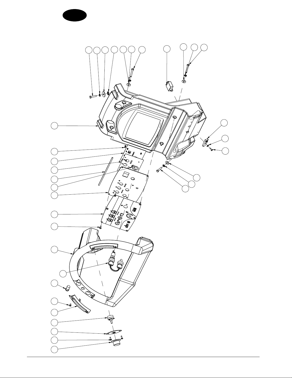
Nilfi sk ALT O
Scrubtec 866, 871, 886, BOOST 8, and 871C
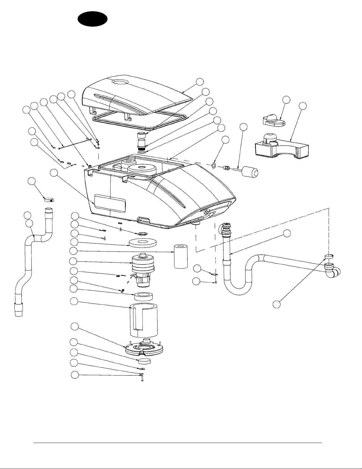
Solution Tank Assembly
26
25
1
2
4
3
5
26
7
6
9
8
24
23
28
22
28
21
-30- FORM NO. 71492A Nilfi sk ALTO Operator’s Manual (EN) - SCRUBTEC 866, 871, 866, Boost 8 and 871C
20
19
18
17
10
11
12
8
13
14
14
15
16
Page 31

Nilfi sk ALTO
Scrubtec 866, 871, 886, BOOST 8, and 871C
Solution Tank Assembly Parts List 12/08
Ref # Part No. Description Qty
1 39887A Gasket Handle 3
2 61930A Rod, Recovery Tank Prop 1
3 170860 Washer, Flat 5/16 2
4 80317A Washer, Bowed .455 ID x .740 OD 1
5 88630A Bolt, M6-1 x 8 x 10MM SHSB 1
6 30796A Tank, Solution 1
7 71496A Label, Nilfi sk ALTO 1
8 80196A Nut, M5-.8 Nylock SS 2
9 80205A Screw, M5 x 0.8 x 20MM Pan Head 1
10 80176A Screw, M5 x 12 PHSS 1
11 54773A Lanyard 1
12 30804A Lid, Solution Rear Fill 1
13 30792A Hose, Level/Drain 1
14 980643 Washer, 7/16 OD x .036 THK 4
15 964004 Screw, M5-.8 x 16MM PN ST PH 2
16 9095149000 Cord Wrap 1
17 722030 Clamp, Hose 1
18 32100A Connector, Straight 2
19 31242A Bushing 2
20 9097028000 Valve, Solution 1
21 59614A Valve, Battery Drain 1
22 34704A Hose, Clear Vinyl 1
23 820207 Adapter, Solution Hose 1
24 9095286000 Gasket, Valve Solution 1
26 40172A Cable, Series (Ring Style) 3
41206A Cable, Series (Taper Style) 3
27 41060A Cable, Battery (Ring Style) 1
41080A Cable, Battery (Taper Style) 1
28 50248A Clamp, Hose 2
ENGLISH
EN
Nilfi sk ALTO Operator’s Manual (EN) - SCRUBTEC 866, 871, 866, Boost 8 and 871C FORM NO. 71492A - 31 -
Page 32
ENGLISH
33
21
32
31
30
12
34
28
35
36
EN
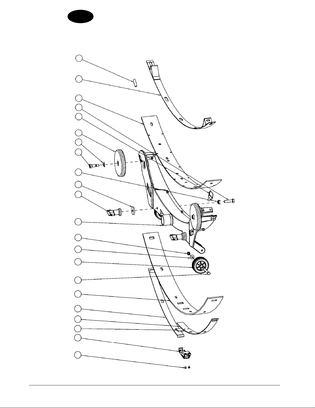
Nilfi sk ALT O
Scrubtec 866, 871, 886, BOOST 8, and 871C
Recovery Tank Assembly Drawing 12/08
1
2
3
4
5
6
9
10
8
7
37
29
23
22
19
21
20
18
16
15
14
26
25
24
17
13
27
11
38
36
12
-32- FORM NO. 71492A Nilfi sk ALTO Operator’s Manual (EN) - SCRUBTEC 866, 871, 866, Boost 8 and 871C
Page 33

Nilfi sk ALTO
Scrubtec 866, 871, 886, BOOST 8, and 871C
Recovery Tank Assembly Parts List 12/08
Ref # Part No. Description Qty
1 30798A Lid, Recovery Tank 1
2 58069A Screen, Vac Filter 1
3 39718A Gasket, Recovery Lid 1
4 30805A Tube, Stand 1
5 837304 O-Ring 1
6 30797A Tank, Recovery 1
7 87612A Seal, Washer 1
8 40002A Switch, Float Electrical 1
9 30827A Lid, Tray Debris 1
10 30791A Tray, Debris 1
11 30799A Hose, Drain 1
12 54774A Clamp, Hose 2
13 80410A Screw, 6MM x 1.00 x 35MM Lg Hex 3
14 87026A Washer, 1/4 Flat SS 3
15 9096638000 Plate Cover 3
16 9096672000 Filter 1
17 9096051000 Cover, Vac 1
18 9096491000 Panel, Acoustic Insulation 1
19 9096490000 Gasket, Vac 1
20 43401A Housing, Connector 2
21 41809A Contact, Housing Connector 4
22 9097367000 Motor, Vacuum 1
23 9096442000 Pipe, Acoustic Insulation 1
24 30823A Gasket, Vac Motor 1
25 80179A Screw, M6 x 15 2
26 52548A Tab, 1/4” Screw 2
27 920797 Nut, Drain Valve 1
28 71451A Label, Scrubtec BOOST 8 2
71447A Label, Scrubtec 866 2
71448A Label, Scrubtec 871 2
71450A Label, Scrubtec 886 2
71449A Label, Scrubtec 871C 2
29 30832A Hose, Squeegee 1
30 43402A Housing, Connector 2
31 80363A Screw, M5 x 12 BT 2
32 9096634000 Cable 2
33 82100A Locknut, 1/2” Conduit 1
34 9096643000 Plate 2
35 9096679000 Spacer 1
36 80057A Screw, M4-.7 x 10 4
37 53371A Clamp, Hose (“P” Trap) 2
38 60367A Plate, Retainer 2
ENGLISH
EN
Nilfi sk ALTO Operator’s Manual (EN) - SCRUBTEC 866, 871, 866, Boost 8 and 871C FORM NO. 71492A - 33 -
Page 34
ENGLISH
EN
16
Nilfi sk ALT O
Scrubtec 866, 871, 886 and BOOST 8
Handle Assembly Drawing 9/10
17
25
26
18
17
19
20
18
17
19
1510
14
13
23
24 12
11
2
9
21
22
2
18
17
16
8
7
56
2341
-34- FORM NO. 71492A Nilfi sk ALTO Operator’s Manual (EN) - SCRUBTEC 866, 871, 866, Boost 8 and 871C
revised 9/10
Page 35

Nilfi sk ALTO
Scrubtec 866, 871, 886 and BOOST 8
Handle Assembly Parts List 9/10
Ref # Part No. Description Qty
1 50962A Knob, Speed Control 1
2# 962957 Screw, 10-16 x 1/2 Self Tap 10
3 61922A Retainer, 5K Potentiometer 1
4 41078A Harness, Potentiometer Asm. 1
5 11131A Switch, Control Handle Asm. 2
6 80192A Screw, M5-0.8 x 10MM Oval Phil. 4
7 52556A Switch, Push Button 1
8 1462888000 Switch, Key 1
9 30785A Handle, Control 1
10 71425A Label, Control Panel 1
11 61929A Panel, Control 1
12 39886A Gasket, Console 9.50 1
13 41067A Board, Function 1
14 50267A Screw, 8-32 x .375 4
15 30784A Housing, Control 1
16 87902A Screw, 6MM x 1.00 x 30MM LG Hex 4
17 980614 Washer, 1/4” Starlock, External 8
18 87007A Washer Control Shaft 6
19 88628A Screw, 6MM x 1.00 x 45MM LG Hex 4
20 41431B Breaker, 35A Circuit 2
21 39888A Retainer, Drain Hose 1
22 980643 Washer, 7/16 OD x .036 THK 2
23 30831A Insulator, Mylar 1
24 61948A Washer, Tab Ground 1
25 980205 Washer, .31 I.D. x 1.06 O.D. 2
26 980666 Washer, 3/8 Starlock 2
NI 41063A Harness, Key Switch 1
ENGLISH
EN
# = Revised or new since last update
Nilfi sk ALTO Operator’s Manual (EN) - SCRUBTEC 866, 871, 866, Boost 8 and 871C FORM NO. 71492A - 35 -
revised 9/10
Page 36

ENGLISH
EN
16
Nilfi sk ALT O
Scrubtec 871C
Handle Assembly Drawing 9/10
17
25
26
18
17
19
20
18
17
19
2
9
1510
14
13
23
24 12
11
21
22
2
18
17
16
8
7
56
2341
-36- FORM NO. 71492A Nilfi sk ALTO Operator’s Manual (EN) - SCRUBTEC 866, 871, 866, Boost 8 and 871C
revised 9/10
Page 37

Nilfi sk ALTO
Scrubtec 871 C
Handle Assembly Parts List 9/10
Ref # Part No. Description Qty
1 50962A Knob, Speed Control 1
2# 962957 Screw, 10-16 x 1/2 Self Tap 10
3 61922A Retainer, 5K Potentiometer 1
4 41078A Harness, Potentiometer Asm. 1
5 11131A Switch, Control Handle Asm. 2
6 80192A Screw, M5-0.8 x 10MM Oval Phil. 4
7 52556A Switch, Push Button 1
8 1462888000 Switch, Key 1
9 30785A Handle, Control 1
10 71484A Label, Control Panel Cyl. 1
11 61929A Panel, Control 1
12 39886A Gasket, Console 9.50 1
13 41067A Board, Function 1
14 50267A Screw, 8-32 x .375 4
15 30784A Housing, Control 1
16 87902A Screw, 6MM x 1.00 x 30MM LG Hex 4
17 980614 Washer, 1/4” Starlock, External 8
18 87007A Washer Control Shaft 6
19 88628A Screw, 6MM x 1.00 x 45MM LG Hex 4
20 41422B Breaker, 25A Circuit, Traverse 2
21 39888A Retainer, Drain Hose 1
22 980643 Washer, 7/16 OD x .036 THK 2
23 30831A Insulator, Mylar 1
24 61948A Washer, Tab Ground 1
25 980205 Washer, .31 I.D. x 1.06 O.D. 2
26 980666 Washer, 3/8 Starlock 2
NI 41063A Harness, Key Switch 1
ENGLISH
EN
# = Revised or new since last update
Nilfi sk ALTO Operator’s Manual (EN) - SCRUBTEC 866, 871, 866, Boost 8 and 871C FORM NO. 71492A - 37 -
revised 9/10
Page 38

ENGLISH
EN
Nilfi sk ALT O
Scrubtec 866, 871, 886, BOOST 8, and 871C
Electrical Box Assembly Drawing 10/08
20
19
18
16
17
12
34 5
6
7
8
9
15
14
13
12
10
11
3
-38- FORM NO. 71492A Nilfi sk ALTO Operator’s Manual (EN) - SCRUBTEC 866, 871, 866, Boost 8 and 871C
Page 39

Nilfi sk ALTO
Scrubtec 866, 871, 886, BOOST 8, and 871C
Electrical Box Assembly Drawing 12/08
Ref # Part No. Description Qty
1 80249A Screw, M5-.8 x 12MM Hex 3
2 980643 Washer, 7/16 OD x .036 THK 3
3 962027 Screw, 8-32 x 1/2 P.H. 3
4 61933A Plate, Electrical 1
5 41068B Controller, I-Drive 24V Traverse 1
6 80380A Screw, 8-32 x 1 1/4” P.H. 2
7 41810A Contactor, Brush 24V 1
8 980614 Washer, 1/4” Starlock External 2
9 85391A Screw, 1/4-20 x .625 Pan Hd. 2
10 Ref. Relay Holder
11 54764A Insert, Hex 1/4-20 UNC 2
12 41075A Relay 1
13 Ref. Fuse Holder
14 41073A Fuse, 30A (see WARNING below) 1
15 962979 Screw, 6-32 x 1/2 PN ST PH 2
16 920056 Nut, 6-32 E.S.N.A. Nylock 2
17 Ref. Fuse Holder
18 41074A Fuse, 60A (see WARNING below) 1
19 41069B Relay, i-Drive 24V Traverse 1
20 54763A Insert, Hex #8-32 UNC 7
NI 41065B Harness, Traverse 1
NI 41061A Harness, Machine 1
(included in 41061A Harness)
(included in 41061A Harness)
(included in 41061A Harness)
1
1
1
ENGLISH
EN
WARNING: To reduce the risk of fi re, when replacing
fuse, replace only with same type and rating
of fuse that comes with machine.
Nilfi sk ALTO Operator’s Manual (EN) - SCRUBTEC 866, 871, 866, Boost 8 and 871C FORM NO. 71492A - 39 -
Page 40

ENGLISH
EN
Nilfi sk ALT O
Scrubtec 866, 871, 886, BOOST 8, and 871C
Squeegee Holder Assembly Drawing 12/08
10
26
25
24
23
22
30
28
27
1
3
2
4
29
5
6
7
8
9
10
11
12
13
14
15
9
9
17
17
13
18
19
21
20
-40- FORM NO. 71492A Nilfi sk ALTO Operator’s Manual (EN) - SCRUBTEC 866, 871, 866, Boost 8 and 871C
16
Page 41

Nilfi sk ALTO
Scrubtec 866, 871, 886, BOOST 8, and 871C
Squeegee Holder Assembly Parts List 12/08
Ref # Part No. Description Qty
1 52557A Knob, Lift 1
2 980666 Washer, 3/8 Starlock External 1
3 85389A Screw, 3/8-16 x 5/8 1
4 V17027 Joint, Ball 1
5 9097366000 Cable, Lift 1
6 9096537000 Spring, Squeegee Left 1
7 80199A Nut, M6-1.00 Nylock S.S. 1
8 925044 Pin, Cotter .094 x 1.00 2
9 80198A Nut, M8-1.25 Nylock S.S. 4
10 980651 Washer, 5/16 Flat 4
11 9096052000 Support, Spring 1
12 9096538000 Spring, Squeegee Right 1
13 87613A Washer, Flat .22 x .64 x .10 Nylon 2
14 61953A Plate, Squeegee Support 1
15 9096497000 Pin, Squeegee Mounting 1
16 80163A Nut, M8-1 Hex 1
17 38708A Spacer 2
18 80223A Nut, M10-1.5 Nylock 1
19 L08602422 Spacer 1
20 L08601509 Pin 1
21 54699A Knob, M8 x 55 1
22 9096045000 Bracket, Squeegee 1
23 964054 Screw, M6-1 x 25MM Hex 1
24 87007A Washer 2
25 1462258000 Spacer 1
26 9096495000 Screw, Socket Head 2
27 61952A Lever, Squeegee Lift 1
28 80179A Screw, M6 x 15 Pan 1
29 80171A Nut, M6 Hex 1
30 88640A Nut, M6-1 Acorn 1
ENGLISH
EN
Nilfi sk ALTO Operator’s Manual (EN) - SCRUBTEC 866, 871, 866, Boost 8 and 871C FORM NO. 71492A - 41 -
Page 42
ENGLISH
EN
Nilfi sk ALT O
Scrubtec 866, 871, 886, BOOST 8, and 871C
Squeegee Assembly Drawing 10/08
18 19 20
13
1415
17
16
21
10 11 12
9
8
7
6
34 5
22
12
-42- FORM NO. 71492A Nilfi sk ALTO Operator’s Manual (EN) - SCRUBTEC 866, 871, 866, Boost 8 and 871C
Page 43

Nilfi sk ALTO
Scrubtec 866, 871, 886, BOOST 8, and 871C
Squeegee Assembly Parts List 1/10
For Models with Squeegee Size 32.5”
Ref # Part No. Description Qty
1 83009A Rivet, Pop 5/32 Dia., .126-.187 G 2
2 9098321000 Latch Squeegee 1
3 9097356000 Support, Squeegee 1
4 9097357000 Strap, Wldmt., Squeegee 1
5 30816U Blade, 32.5” Rear Urethane 1
6 88629A Screw, M6-1 x 55MM Hex 2
7 9096505000 Wheel, Squeegee 2
8 87026A Washer, 1/4 Flat S.S. 2
9 80199A Nut, M6 x 1.00 Nylock S.S. 2
10 29927A Frame, 32.5” Squeegee 1
11 9098257000 Nut Thumb 2
12 9096682000 Washer, Rubber 2
13 962157 Screw, 5/16-18 x 1.25 Hex 2
14 54647A Knob, M8 x 30 1
15 88609A Screw, 5/16 x 3/8 x 5/8 SHSS 2
16 80317A Washer, Bowed .455 ID x 7.40 OD 2
17 30048A Guide, Wheel 2
18 30817U Blade, 32.5” Front Urethane 1
19 60465A Strap, Wldmt., Squeegee 1
20 88632A Screw, Set M8-1.25 x 30MM 1
21 60564A Shim, Screw 2
22 39717A Pad, Squeegee 1
ENGLISH
EN
Nilfi sk ALTO Operator’s Manual (EN) - SCRUBTEC 866, 871, 866, Boost 8 and 871C FORM NO. 71492A - 43 -
revised 1/10
Page 44

ENGLISH
EN
Nilfi sk ALT O
Scrubtec 866, 871, 886, BOOST 8, and 871C
Squeegee Assembly Drawing 10/08
18 19 20
13
1415
17
16
21
10 11 12
9
8
7
6
34 5
22
12
-44- FORM NO. 71492A Nilfi sk ALTO Operator’s Manual (EN) - SCRUBTEC 866, 871, 866, Boost 8 and 871C
Page 45

Nilfi sk ALTO
Scrubtec 866, 871, 886, BOOST 8, and 871C
Squeegee Assembly Parts List 1/10
For Models with Squeegee Size 35”
Ref # Part No. Description Qty
1 83009A Rivet, Pop 5/32 Dia., .126-.187 G 2
2 9098321000 Latch Squeegee 1
3 9097361000 Support, Squeegee 1
4 9097362000 Strap, Wldmt., Squeegee 1
5 30815U Blade, 35” Rear Urethane 1
6 88629A Screw, M6-1 x 55MM Hex 2
7 9096505000 Wheel, Squeegee 2
8 87026A Washer, 1/4 Flat S.S. 2
9 80199A Nut, M6 x 1.00 Nylock S.S. 2
10 29928A Frame, 35” Squeegee 1
11 9098257000 Nut Thumb 2
12 9096682000 Washer, Rubber 2
13 962157 Screw, 5/16-18 x 1.25 Hex 2
14 54647A Knob, M8 x 30 1
15 88609A Screw, 5/16 x 3/8 x 5/8 SHSS 2
16 80317A Washer, Bowed .455 ID x 7.40 OD 2
17 30048A Guide, Wheel 2
18 30818U Blade, 35” Front Urethane 1
19 60466A Strap, Wldmt., Squeegee 1
20 88632A Screw, Set M8-1.25 x 30MM 1
21 60564A Shim, Screw 2
22 39717A Pad, Squeegee 1
ENGLISH
EN
Nilfi sk ALTO Operator’s Manual (EN) - SCRUBTEC 866, 871, 866, Boost 8 and 871C FORM NO. 71492A - 45 -
revised 1/10
Page 46

ENGLISH
EN
Nilfi sk ALT O
Scrubtec 866, 871, 886, BOOST 8, and 871C
Squeegee Assembly Drawing 10/08
18 19 20
13
1415
17
16
21
10 11 12
9
8
7
6
34 5
22
12
-46- FORM NO. 71492A Nilfi sk ALTO Operator’s Manual (EN) - SCRUBTEC 866, 871, 866, Boost 8 and 871C
Page 47

Nilfi sk ALTO
Scrubtec 866, 871, 886, BOOST 8, and 871C
Squeegee Assembly Parts List
For Models with Squeegee Size 41”
Ref # Part No. Description Qty
1 83009A Rivet, Pop 5/32 Dia., .126-.187 G 2
2 9098321000 Latch Squeegee 1
3 9097375000 Support, Squeegee 1
4 9097376000 Support, Squeegee 1
5 30814U Blade-Squeegee 42in 1
6 88629A Screw, M6-1 x 55MM Hex 2
7 9096505000 Wheel, Squeegee 2
8 87026A Washer, 1/4 Flat S.S. 2
9 80199A Nut, M6 x 1.00 Nylock S.S. 2
10 29929A Frame, 42” Squeegee 1
11 9098257000 Nut Thumb 2
12 9096682000 Washer, Rubber 2
13 962157 Screw, 5/16-18 x 1.25 Hex 2
14 54647A Knob, M8 x 30 1
15 88609A Screw, 5/16 x 3/8 x 5/8 SHSS 2
16 80317A Washer, Bowed .455 ID x 7.40 OD 2
17 30048A Guide, Wheel 2
18 30819U Blade, 42” Front Urethane 1
19 60546A Strap, Wldmt., Squeegee 1
20 88632A Screw, Set M8-1.25 x 30MM 1
21 60564A Shim, Screw 2
22 39717A Pad, Squeegee 1
ENGLISH
EN
Nilfi sk ALTO Operator’s Manual (EN) - SCRUBTEC 866, 871, 866, Boost 8 and 871C FORM NO. 71492A - 47 -
revised 6/10
Page 48

ENGLISH
EN
Nilfi sk ALT O
Scrubtec 866, 871, 886, BOOST 8, and 871C
Frame Assembly
-48- FORM NO. 71492A Nilfi sk ALTO Operator’s Manual (EN) - SCRUBTEC 866, 871, 866, Boost 8 and 871C
revised 6/10
Page 49

Nilfi sk ALTO
Scrubtec 866, 871, 886, BOOST 8, and 871C
Frame Assembly Parts List 9/10
ENGLISH
EN
Ref # Part No. Description Qty
1 88633A Screw, M8 x 85 Hex Head 2
2 170860 Washer, Flat 5/16 4
3 61937A Spacer, .590 OD x .328 ID 2
4 88620A Screw, M12 x 90M Hex 1
5 9097456000 Lever 1
6 88635A Screw, M8 x 75 Hex Head 1
7 9096112000 Spacer 2
8 9097402000 Actuator (for all models except BOOST) 1
40280A Actuator (for BOOST 28/32 models only) 1
9 80198A Nut, M8-1.25 Nylock S.S. 3
10 88618A Nut, M12 Nylon Insert 1
11 88626A Screw, M6-1 x 40MM Hex 1
12 87026A Washer, 1/4 Flat S.S. 6
13 1462258000 Spacer 2
14 80199A Nut, M6-1.00 Nylock S.S. 8
15 9097368000 Support, Jack Motor 1
16 88616A Screw, M10 x 75M Hex 1
17 87054A Washer Fender .375 5
18 80214A Screw, M6 x 1 x 12 2
19 59789A Valve, Solution 1
20 30828A Hose, Clear x 25.00 Long 1
21 88624A Screw, M5 x 12MM Hex Self Tap 4
22 61932A Bracket, Solution Valve 1
23 88623A Nut, M4-.7 Nylock Insert 2
24 9097370000 Bracket, Filter 1
25 9097404000 Filter, Water 1
26 722030 Clamp, Hose 4
27 80057A Screw, M4-.7 x 10 2
28 30829A Hose, Clear x 3.00 Long 1
29 57994A Screw, M6-1 x 20 9
Ref # Part No. Description Qty
30 980614 Washer, 1/4” Starlock External 3
31 980205 Washer, .31 ID x 1.06 OD 2
32 69639A Strap, Static 1
33 88612A Washer, Lock M10 10
34 88614A Screw, M10-1.5 x 20MM 6
35 61949A Bracket, Ground Strap 1
36 41081A Cord, Charger NEMA NOTE 1 1
37# 56380160 Transaxle TSBCL2010-25, TSBCL2009-02 1
[ ] 40628A Carbon Brushes, Transaxle (Set) 1
40 88611A Washer, Flat M10 6
41 88613A Screw, M10-1.5 x 16MM Hex 4
42 9095202000 Caster, Rear 1
43 80196A Nut, M5-.8 Nylock SS 4
44 61934A Bracket, Brake 1
45 54772A Clamp, Toggle Straight Line 1
46 80249A Screw, M5-.8 x 12MM Hex 4
47 920160 Nut, 5/16 Jam Hex 1
48 962157 Screw, 5/16-18 x 1.25 Hex Hd 1
49 60580A Wheel, 10” Foam Filled 2
50 980652 Washer, 5/16 Lock 8
51 80183A Bolt, M8-1.25 x 20, Hex 8
52 980657 Washer, Lock 1/4 4
53
# 41077A Charger, Battery NOTE 1 TSBCL2009-04 1
54 61931A Chassis, Wldmt 1
55 80223A Nut, M10-1.5 Nylock 1
56 9096113000 Spacer 2
57 54689A Gas Spring 500N 1
58 71017A Label, Moving Parts 1
[ ] 41062A Harness Chrg Jumper NOTE 2 1
[ ] 40512B Charger Battery 25 Amp NOTE 2 1
[ ] 40297A Cable Charger Adapter1 NOTE 2 1
# = Revised or new since last update
[ ] = Not Shown
#NOTE 1: Only used on models with on-board charger.
#NOTE 2: Only used on models without on-board charger.
Nilfi sk ALTO Operator’s Manual (EN) - SCRUBTEC 866, 871, 866, Boost 8 and 871C FORM NO. 71492A - 49 -
revised 9/10
Page 50

ENGLISH
EN
Nilfi sk ALT O
Scrubtec 866
Brush Head Assembly Drawing 12/08
41
40
39
38
37
34
35
36
35
34
12
42
14
33
1
3
5
2
3
4
5
6
7
8
9
10
11
12
13
14
15
31
32
30
28
29
44
27
26
16
17
18
43
19
21
20
22
9
23
24
25
-50- FORM NO. 71492A Nilfi sk ALTO Operator’s Manual (EN) - SCRUBTEC 866, 871, 866, Boost 8 and 871C
Page 51

Nilfi sk ALTO
Scrubtec 866
Brush Head Assembly Parts List 1/10
Ref # Part No. Description Qty
1 56109717 Tube Jack Motor 1
2 E04016 Spring 2
3 88647A Bushing, Flanged 8
4 9097197000 Lever, Bushing Head Lift 4
5 88617A Screw, M10 x M12 x 16MM SBSH 8
6 980648 Washer, 17/32 x 1 1/16 Plain 1
7 88618A Nut, M12 Nylon Insert 1
8 44809B Motor, Brush 2
NI 40826A Carbon Brushes, Motor (set) 1
9 80199A Nut, M6-1.00 Nylock SS 4
10 57994A Screw, M6-1 x 20 2
11 61925A Plate, 26” Brush Wldmt 1
12 980638 Washer, 3/8 Lock 9
13 962244 Screw, 3/8-16 x .75 Hex 8
14 964002 Screw, M4-.7 x 16MM PH 4
15 55721A Latch 1
16 722030 Clamp, Hose 1
17 30661A Brush Housing L.H. 1
18 30412A Hose, Solution 1
19 59856A Washer, Rubber 2
20 88623A Nut, M4-.7 Nylock Insert 4
21 782002 Clamp, Manifold 2
22 61658A Collar, Brush Driver 2
23 34400B Gimbal, Motor 2
24 962714 Screw, Gimbal Mount 2
25 38035A Driver, Pad 13” Gimbal 2
26 88627A Screw, M6-1 x 40MM PH 2
27 38014A Splitter, Solution 1
28 34705A Hose, Solution 6.00” Lg. 2
29 85610A Screw, 3/8-16 x 2.5” PH 1
30 80183A Bolt, M8-1.25 x 20 Hex 3
31 69186A Tab, Latch Brush 1
32 30662A Brush Housing R.H. 1
33 55451A Keeper, Latch 1
34 920248 Nut, 3/8-16 ESNA, JAM 2
35 980645 Washer, 3/8” S.A.E. Flat 2
36 59950A Wheel, Guide 3 1/2” 1
37 80198A Nut, M8-1.25 Nylock S.S. 3
38 61926A Bracket, Head Lift 1
39 88612A Washer, Lock M10 8
40 88619A Screw, M12-1.75 x 160MM Hex 1
41 80223A Nut, M10-1.5 Nylock 8
42 71017A Label, Moving Parts 2
43 53571A Clamp, Hose 1
44 50248A Clamp, Hose 2
ENGLISH
EN
Nilfi sk ALTO Operator’s Manual (EN) - SCRUBTEC 866, 871, 866, Boost 8 and 871C FORM NO. 71492A - 51 -
revised 1/10
Page 52

ENGLISH
EN
Nilfi sk ALT O
Scrubtec 871
Brush Head Assembly Drawing 12/08
41
40
39
38
37
34
35
36
35
34
12
42
14
33
1
3
5
2
3
4
5
6
7
8
9
10
11
12
13
14
15
31
32
30
28
29
44
27
26
16
17
18
43
19
21
20
22
9
23
24
25
-52- FORM NO. 71492A Nilfi sk ALTO Operator’s Manual (EN) - SCRUBTEC 866, 871, 866, Boost 8 and 871C
Page 53

Nilfi sk ALTO
Scrubtec 871
Brush Head Assembly Parts List 1/10
Ref # Part No. Description Qty
1 56109717 Tube Jack Motor 1
2 E04016 Spring 2
3 88647A Bushing, Flanged 8
4 9097197000 Lever, Bushing Head Lift 4
5 88617A Screw, M10 x M12 x 16MM SBSH 8
6 980648 Washer, 17/32 x 1 1/16 Plain 1
7 88618A Nut, M12 Nylon Insert 1
8 44809B Motor, Brush 2
NI 40826A Carbon Brushes, Motor (set) 1
9 80199A Nut, M6-1.00 Nylock SS 4
10 57994A Screw, M6-1 x 20 2
11 61924A Plate, 28” Brush Wldmt 1
12 980638 Washer, 3/8 Lock 9
13 962244 Screw, 3/8-16 x .75 Hex 8
14 964002 Screw, M4-.7 x 16MM PH 4
15 55721A Latch 1
16 722030 Clamp, Hose 1
17 30574A Brush Housing L.H. 1
18 30412A Hose, Solution 1
19 59856A Washer, Rubber 2
20 88623A Nut, M4-.7 Nylock Insert 4
21 782002 Clamp, Manifold 2
22 61658A Collar, Brush Driver 2
23 34400B Gimbal, Motor 2
24 962714 Screw, Gimbal Mount 2
25 38036A Driver, Pad 14” Gimbal 2
26 88627A Screw, M6-1 x 40MM PH 2
27 38014A Splitter, Solution 1
28 34705A Hose, Solution 6.00” Lg. 2
29 85610A Screw, 3/8-16 x 2.5” PH 1
30 80183A Bolt, M8-1.25 x 20 Hex 3
31 69186A Tab, Latch Brush 1
32 30575A Brush Housing R.H. 1
33 55451A Keeper, Latch 1
34 920248 Nut, 3/8-16 ESNA, JAM 2
35 980645 Washer, 3/8” S.A.E. Flat 2
36 59950A Wheel, Guide 3 1/2” 1
37 80198A Nut, M8-1.25 Nylock S.S. 3
38 61926A Bracket, Head Lift 1
39 88612A Washer, Lock M10 8
40 88619A Screw, M12-1.75 x 160MM Hex 1
41 80223A Nut, M10-1.5 Nylock 8
42 71017A Label, Moving Parts 2
43 53571A Clamp, Hose 1
44 50248A Clamp, Hose 2
ENGLISH
EN
Nilfi sk ALTO Operator’s Manual (EN) - SCRUBTEC 866, 871, 866, Boost 8 and 871C FORM NO. 71492A - 53 -
revised 1/10
Page 54
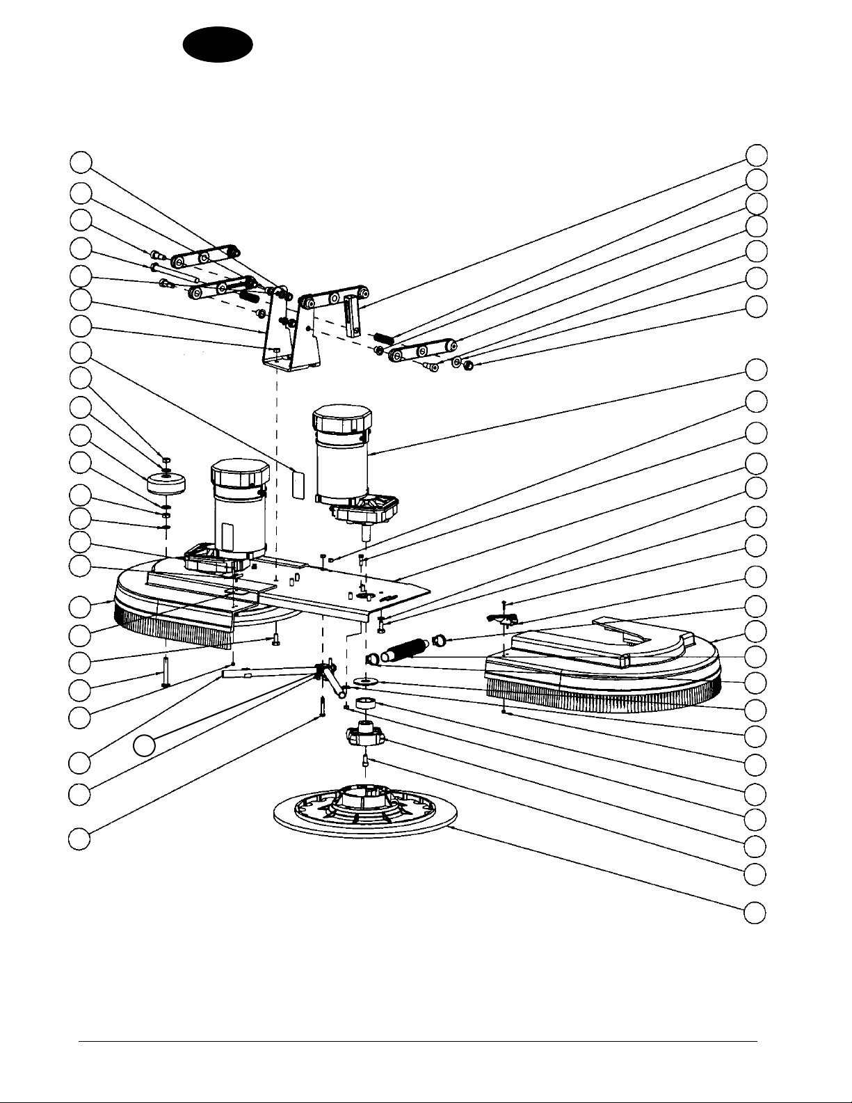
ENGLISH
EN
Nilfi sk ALT O
Scrubtec 886
Brush Head Assembly Drawing 12/08
41
40
39
38
37
42
34
35
36
35
34
33
14
32
1
3
5
2
3
4
5
6
7
8
9
10
11
12
13
14
15
31
30
13
29
21
28
27
26
44
16
17
18
43
19
20
21
22
9
23
24
25
-54- FORM NO. 71492A Nilfi sk ALTO Operator’s Manual (EN) - SCRUBTEC 866, 871, 866, Boost 8 and 871C
Page 55

Nilfi sk ALTO
Scrubtec 886
Brush Head Assembly Drawing 1/10
Ref # Part No. Description Qty
1 56109717 Tube Jack Motor 1
2 E04016 Spring 2
3 88647A Bushing, Flanged 8
4 9097197000 Lever, Bushing Head Lift 4
5 88617A Screw, M10 x M12 x 16MM SBSH 8
6 980648 Washer, 17/32 x 1 1/16 Plain 1
7 88618A Nut, M12 Nylon Insert 1
8 41046A Motor, Brush 2
NI 40261A Carbon Brushes (set) 1
9 80199A Nut, M6-1.00 Nylock SS 4
10 57994A Screw, M6-1 x 20 2
11 61923A Plate, 34” Brush Wldmt 1
12 980652 Washer, 5/16 Lock 8
13 80183A Bolt, M8-1.25 x 20 Hex 11
14 964002 Screw, M4-.7 x 16MM PH 4
15 55721A Latch 1
16 722030 Clamp, Hose 1
17 30583A Brush Housing L.H. 1
18 30412A Hose, Solution 1
19 59856A Washer, Rubber 2
20 782002 Clamp, Manifold 2
21 88623A Nut, M4-.7 Nylock Insert 4
22 61658A Collar, Brush Driver 2
23 34400B Gimbal, Motor 2
24 962714 Screw, Gimbal Mount 2
25 38034A Driver, Pad 17 Gimbal 2
26 88627A Screw, M6-1 x 40MM PH 2
27 38014A Splitter, Solution 1
28 30453A Hose, Clear Vinyl 2
29 85610A Screw, 3/8-16 x 2.5” PH 1
30 69186A Tab, Latch Brush 1
31 30584A Brush Housing R.H. 1
32 55451A Keeper, Latch 1
33 980638 Washer, 3/8 Lock 1
34 920248 Nut, 3/8-16 ESNA, JAM 2
35 980645 Washer, 3/8” S.A.E. Flat 2
36 59950A Wheel, Guide 3 1/2” 1
37 80198A Nut, M8-1.25 Nylock S.S. 3
38 61926A Bracket, Head Lift 1
39 88612A Washer, Lock M10 8
40 88619A Screw, M12-1.75 x 160MM Hex 1
41 80223A Nut, M10-1.5 Nylock 8
42 71017A Label, Moving Parts 2
43 53571A Clamp, Hose 1
44 50248A Clamp, Hose 2
ENGLISH
EN
Nilfi sk ALTO Operator’s Manual (EN) - SCRUBTEC 866, 871, 866, Boost 8 and 871C FORM NO. 71492A - 55 -
revised 1/10
Page 56

ENGLISH
EN
Nilfi sk ALT O
Scrubtec BOOST 8
Brush Head Assembly Drawing 11329A 3/10
-56- FORM NO. 71492A Nilfi sk ALTO Operator’s Manual (EN) - SCRUBTEC 866, 871, 866, Boost 8 and 871C
revised 3/10
Page 57

Nilfi sk ALTO
Scrubtec 866, 871, 886, BOOST 8, and 871C
Brush Head Assembly Drawing 11329A 9/10
ENGLISH
EN
Ref # Part No. Description Qty
1 E04016 Spring 2
2 170860 Washer, Flat 5/16 2
3 722030 Clamp, Hose 1
4 782002 Clamp, Manifold 3
5 925589 Pin, Roll 1
6 56001881 Scr, Flt Soc 1/4-20 NOTE 1
7 962139 Screw, 1/4-20x.625 Hex Cap 4
8 88618A Nut, M12 Nylon Insert 1
9 980638 Washer, 3/8 Lock 2
10 980646 Washer, 1/4” Flat 4
11 980648 Washer 17/32 X 1 1/16 Plain 1
12 980657 Washer, Lock 1/4 1
13 997001 Pad, Red, 28” 1
14 56109717 Tube Jack Motor 1
15 10309A Tube Drip 28” 1
16 30048A Guide, Wheel 4
17 30206A Bumper 1
18 56380192 Shield Boost Bearing NOTE 1
19 30663A Plate, Driver 1
# 56380210 Kit, Flex Plate 28” NOTE 1 TSBCL2010-12 1
20
21 30670A Spacer, Nylon 2
22 30671A Spacer, Nylon 2
23 30680A Hose, Solution (Flex) 1
# 56380247 Motor, 24vdc 1
24
* 11055A Carbon Brushes, Motor (set) 1
25 50248A Clamp, Hose 1
26 50736A Bearing 1
27 56380235 Isolator Kit Boost 28”,32” NOTE 1
# 56380173 Bushing-Flex Plate NOTE 1 TSBCL2010-12 4
28
29 61425A Retainer, Bumper 1
TSBCL2010-12 4
TSBCL2010-12 1
TSBCL2010-12 1
Ref # Part No. Description Qty
30 61724A Retainer, Eccentric 1
31 61729B Plate-Upper 28 1
32 61733B Bracket, Lift 2
33 61753B Eccentric 1
34 61775A Retainer, Bearing 1
35 61782A Sleeve, Guide Wheel 4
36 61828S Stud Stablizer_Short 2
37 61935A Arm, Lift, Right 1
38 61936A Arm, Lift, Left 1
39 61938A Guard, Front 1
40 80054A Screw, M10-1.5 X40mm 2
41 80103A Bolt, 3/8-24 X 1.0 Hex 2
42 80162A Nut, M10 Hex 4
43 80252A Screw, 1/4-20 X 1 HH S.S. 1
44 80296A Screw #10-24 X 7/16 Type 23 5
45 80298A Screw, 1/4-20 X 2.00 Hex Cap 2
46 80317A Washer Bowed .455 Id X .740 O.D. 4
47 81217A Nut, 1/4-20 Hex Esna 13
48 88619A Scr, M12-1.75 X 160mm Hex 1
49 56003825 Scr-Button Soc Ss NOTE 1
50 84237A Screw, 10-32 X .50 P.H. 3
51 85301A Screw, 1/4-20 X 1 1/4 C.R.P.H. 4
52 85395A Screw, 1/4-20 X 1/2” P.H. 3
53 87607A Washer, Nylon 1.25 X .52 X .06 Flat 4
54 88612A Washer, Lock M10 2
55 56380241 Boost-Label 1
56 71075A Label, Brush Plate 28 1
57 71017A Label, Moving Parts 2
# = Revised or new since last update
* = Optional, Not Included
TSBCL2010-12 4
NOTE 1: Customers ordering parts for machines built before April 2010 need to order 28” Flex Plate Kit 56380210 to
replace any or all of these Items for repair.
Nilfi sk ALTO Operator’s Manual (EN) - SCRUBTEC 866, 871, 866, Boost 8 and 871C FORM NO. 71492A - 57 -
revised 9/10
Page 58

ENGLISH
29
25
30
EN
17
31
Nilfi sk ALT O
Scrubtec 871C
Brush Head Assembly Drawing 12/08
20
13
32
33
22
34
35
36
37
29
27
24
21
19
17
15
13
12
10
9
8
7
5
28
26
25
22 23
20
18
16
14
11
1538
39
38
40
41
42
17
43
4445
46
43
43
472023
65
4
61
63
62
60
59
58
57
56
55
54
53
64
56
3
12
66
-58- FORM NO. 71492A Nilfi sk ALTO Operator’s Manual (EN) - SCRUBTEC 866, 871, 866, Boost 8 and 871C
48
4920
43
50
51
52
Page 59

Nilfi sk ALTO
Scrubtec 871C
Brush Head Assembly Drawing 1/10
ENGLISH
EN
Ref # Part No. Description Qty
1 88618A Nut, M12 Nylon Insert 1
2 980648 Washer, 17/32 x 1 1/16 Plain 1
3 9097197000 Lever, Brush Head Lift 4
4 E04016 Spring 2
5 80223A Nut, M10-1.5 Nylock 9
6 56109717 Tube Jack Motor 1
7 88612A Washer, Lock M10 8
8 88647A Bushing, Flanged 8
9 88617A Screw, M10 x M12 x 16MM SBSH 8
10 88619A Screw, M12-1.75 x 160MM Hex 1
11 9095754000 Spacer 2
12 9095758000 Pulley 2
13 1455828000 Spacer 4
14 88626A Screw, M6-1 x 40MM Hex 2
15 88642A Screw, M6-1.0 x 20MM Flat HD Socket 4
16 56407551 Hub Brush 2
17 51225A Bearing, 6292 Sealed 6
18 9095710000 Spacer 2
19 9095964000 Knob, M8 2
20 87026A Washer, 1/4 Flat SS 19
21 9095756000 Support Brush 2
22 170892 Washer, Lock 1/4 12
23 80195A Screw, M6 x 1.00 x 20MM Hex SS 12
24 9095765000 Bushing, Collar 2
25 51126A Bearing, 6201 4
26 80214A Screw, M6 x 1 x 12 6
27 9095762000 Roller Belt Tensioner 2
28 9095764000 Spacer 2
29 964007 Screw, M6 x 1.00 x 16MM Pan Head 9
30 9095766000 Pin 2
31 9095759000 Pulley, Poly-V 2
32 9095760000 Belt, Poly-V 1
33 9095724000 Cover, Crankcase Belt Right 1
34 80208A Screw, M6 x 1.00 x 10MM Pan Head 4
35 71017A Label, Moving Parts 2
Ref # Part No. Description Qty
36 9095770000 Guard, Splash 4
37 9095769000 Plate, Splash Guard Fix 4
38 88646A Key, Square M5 x 20MM 4
39 9095755000 Pin, Brush Pulley 2
40 1461232000 Spacer 2
41 170860 Washer, Flat 5/16 2
42 9095757000 Support, Brush Pulley 2
43 80199A Nut, M6-1.00 Nylock SS 15
44 9095728000 Hub, Brush 2
45 87039A Washer, Fender 1/4” 2
46 L08602460 Roller, Bumper 2
47 9095752000 Guard, Splash 2
48 980651 Washer, 5/16 Flat 2
49 80198A Nut, M8-1.25 Nylock SS 2
50 39721A Brush, Cylindrical 28” Poly 2
51 9095751000 Frame, Cyl Deck 1
52 9096225000 Container, Dirt 1
53 30680A Hose, Solution 1
54 722030 Clamp, Hose 1
55 9095761000 Belt, Poly-V 1
56 9095725000 Cover, Crankcase Belt Left 1
57 9095803000 Crankcase, Motor Protection Left 1
58 50248A Clamp, Hose 1
59 52414A Union, 3/8 Straight Hosebarb 1
60 30835A Hose, Clear 1
61 54779A Clamp, P 5/8 Steel 1
62 53181A Hosebarb, 3/8 T 1
63 88645A Key, Square M5 x 15MM 2
64 41086A Motor, Electric 600W 24V 2
65 9095802000 Crankcase, Motor Protection Right 1
66 61926A Bracket, Head Lift 1
Nilfi sk ALTO Operator’s Manual (EN) - SCRUBTEC 866, 871, 866, Boost 8 and 871C FORM NO. 71492A - 59 -
revised 1/10
Page 60
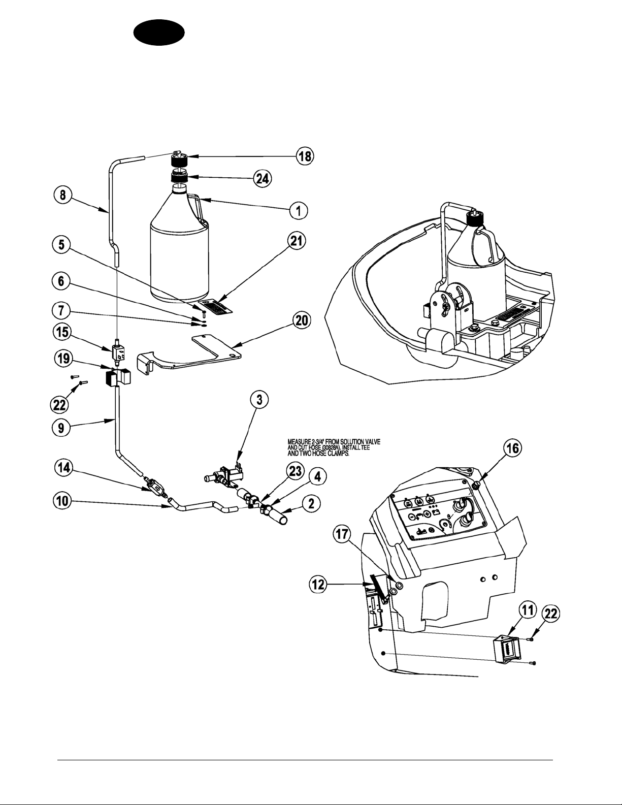
ENGLISH
EN
Nilfi sk ALT O
Scrubtec 866, 871, 886, BOOST 8, and 871C
Chemical Mixing Kit
-60- FORM NO. 71492A Nilfi sk ALTO Operator’s Manual (EN) - SCRUBTEC 866, 871, 866, Boost 8 and 871C
revised 6/10
Page 61

Nilfi sk ALTO
Scrubtec 866, 871, 886, BOOST 8, and 871C
Chemical Mixing Kit
Ref # Part No. Description Qty
1 Ref. Cleaning Solution Bottle 1
2 Ref. From Frame Asm. 1
3 Ref. Valve From Frame Asm. 1
4 722030 Clamp, Hose 2
5 964002 Screw, M4-.7 x 16MM PH 1
6 980621 Washer, External Tooth Lock 1
7 980982 Washer, #10 SAE Flat 1
8 39725A Hose, 1/4” ID x 15.25 Clear 1
9 39726A Hose, 1/4” ID x 11.50 Clear 1
10 39727A Hose, 3/8 x 11.5 Clear 1
11 40850A Module, Chemical 1
12 41084A Harness, Chemical 1
13 53186A Tie, Wire (not illustrated) 10
14 53719A Valve, Check 1
15 53721A Pump, Chemical 1
16 53736A Knob, Adjustment 1
17 87618A Washer, Flat 2
18 54778A Adapter, Cap 38MM 1
19 61772A Bracket, Pump 1
20 61954B Support, Bottle 1
21 71489A Label, Chemical Settings 1
22 85614A Screw, 8-32 x 3/4 PH 4
23 88644A Tee, Reducing 3/8 to 1/2 1
24 9097023000 Adaptor (For Sutter box) 1
ENGLISH
EN
Nilfi sk ALTO Operator’s Manual (EN) - SCRUBTEC 866, 871, 866, Boost 8 and 871C FORM NO. 71492A - 61 -
revised 6/10
Page 62

ENGLISH
EN
Nilfi sk ALT O
Scrubtec 866, 871, 886, BOOST 8, and 871C
Electrical Schematic (pages 62-63) 10/08
-62- FORM NO. 71492A Nilfi sk ALTO Operator’s Manual (EN) - SCRUBTEC 866, 871, 866, Boost 8 and 871C
Page 63

Nilfi sk ALT O
Scrubtec 866, 871, 886, BOOST 8, and 871C
Electrical Schematic (pages 62-63) 10/08
ENGLISH
EN
Nilfi sk ALTO Operator’s Manual (EN) - SCRUBTEC 866, 871, 866, Boost 8 and 871C FORM NO. 71492A - 63 -
Page 64
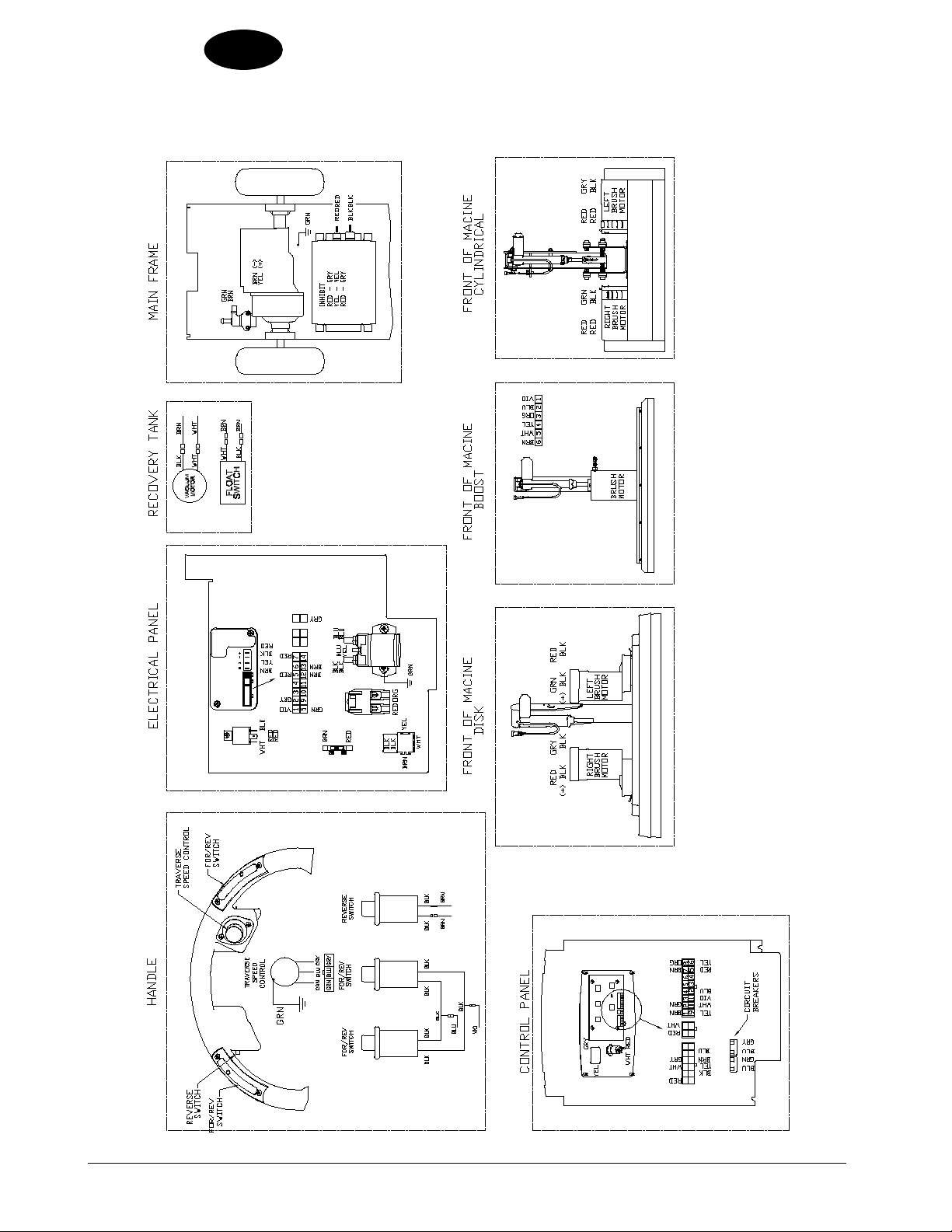
ENGLISH
EN
Nilfi sk ALT O
Scrubtec 866, 871, 886, BOOST 8, and 871C
Connection Diagram 12/08
-64- FORM NO. 71492A Nilfi sk ALTO Operator’s Manual (EN) - SCRUBTEC 866, 871, 866, Boost 8 and 871C
Page 65

ENGLISH
ACCESSORIES
DESCRIPTION Part No.
Power Wand System Kit 11370A
Chemical System Kit 11363A
Hour Meter Kit 11371A
Parking Brake Kit 11372A
Care Kit 14607A
Battery Maintenance System (CBMS) 53391A
32.5” Squeegee Asm. 10398A
35” Squeegee Asm. 10399A
41” Squeegee Asm. 10748A
Scrubtec Boost 8
Description Part No. Description Part No.
Pads & Brushes 35” Squeegee Blades (front & rear)
White Pad (14x28) 5 pack 997002 Urethane Squeegee Blade Kit 11332A
Red Pad (14x28) 5 pack 997001 Linatex Squeegee Blade Kit 11338A
Blue Pad (14x28) 5 pack 997006 Gum Squeegee Blade Kit 11335A
Maroon Pad (14x28) 10 pack 997018
Black Pad (14x28) 5 pack 997000
Poly Brush (14x28) 30752A
Nylon Brush (14x28) 30751A
Grit Brush (14x28) 30753A
Two Sided Velcro 30794A
EN
Scrubtec 866
Description Part No. Description Part No.
Pad Driver & Brushes 32.5” Squeegee Blades (front & rear)
Pad Driver (13”) 38035A Urethane Squeegee Blade Kit 11333A
Poly Brush (13”) 11438A Linatex Squeegee Blade Kit 11339A
Soft Nylon Brush (13”) 11437A Gum Squeegee Blade Kit 11336A
Lite Grit Brush (13”) 10382A
Medium Grit Brush (13”) 11439A
Heavy Grit Brush (13”) 11440A
Nilfi sk ALTO Operator’s Manual (EN) - SCRUBTEC 866, 871, 866, Boost 8 and 871C FORM NO. 71492A - 65 -
revised 9/10
Page 66

ENGLISH
EN
ACCESSORIES
Scrubtec 871
Description Part No. Description Part No.
Pad Driver & Brushes 35” Squeegee Blades (front & rear)
Pad Driver (14”) 38036A Urethane Squeegee Blade Kit 11332A
Poly Brush (14”) 11427B Linatex Squeegee Blade Kit 11338A
Soft Nylon Brush (14”) 10874A Gum Squeegee Blade Kit 11335A
Lite Grit Brush (14”) 10383A
Medium Grit Brush (14”) 11431B
Heavy Grit Brush (14”) 11426B
Scrubtec 886
Description Part No. Description Part No.
Pad Driver & Brushes 41” Squeegee Blades (front & rear)
Pad Driver (17”) 38034A Urethane Squeegee Blade Kit 11331A
Poly Brush (17”) 11424B Linatex Squeegee Blade Kit 11337A
Soft Nylon Brush (17”) 10875A Gum Squeegee Blade Kit 11334A
Lite Grit Brush (17”) 10384A
Medium Grit Brush (17”) 11430B
Heavy Grit Brush (17”) 11425B
Scrubtec 871C
Description Part No. Description Part No.
Brushes 35” Squeegee Blades (front & rear)
#Poly Brush (5.7” dia.) 56412046 Urethane Squeegee Blade Kit 11332A
#Soft Nylon Brush (5.7” dia.) 56412191 Linatex Squeegee Blade Kit 11338A
#Hard Nylon Brush (5.7” dia.) 56412192 Gum Squeegee Blade Kit 11335A
#Lite Grit Brush (5.7” dia.) 56412193
#Medium Grit Brush (5.7”dia.) 56412194
#Heavy Grit Brush (5.7” dia.) 56412195
# = Revised or new since last update
-66- FORM NO. 71492A Nilfi sk ALTO Operator’s Manual (EN) - SCRUBTEC 866, 871, 866, Boost 8 and 871C
revised 9/10
Page 67

Overenstemmelseserklaering Declaration de conformité Samsvarserklaering
Declaration of conformity Verklaring van overeenstemming Vaatimustenmukaisuusvakuutus
Konformitätserklärung Dichiarazione di conformità Atitikties deklaracija
Declaración de conformidad Vastavussertifikaat Osvědčení o shodě
Atbilstības deklarācija Deklaracja zgodności Certifikát súladu
Megfelelősségi nyilatkozat Försäkran om överensstämmelse
Certifikat o ustreznosti
Modell/ Modèle/ Model/ Malli/ Modelo/ Μοντέλο/ Modelo/ Modelis/Модель: Floor Treatment Machines
Type/ Tyyppi/ Tipo/ Τύπος/ Tüüp/ Tipas/ Tips/ Typ/ Típus/ Тип/ Tip: Scrubtec Boost8, Scrubtec 866, Scrubtec 871, Scrubtec 871C, Scrubtec 886
D Der Unterzeichner bestätigt hiermit dass die oben erwähnten Modelle gemäß den folgenden Richtlinien und Normen hergestellt
wurden.
GB The undersigned certify that the above mentioned model is produced in accordance with the following directives and standards.
DK Undertegnede attesterer herved, at ovennævnte model er produceret i overensstemmelse med følgende direktiver og standarder.
N Undertegnede attesterer att ovennevnte modell är produsert I overensstemmelse med fölgende direktiv og standarder.
E El abajo firmante certifica que los modelos arriba mencionados han sido producidos de acuerdo con las siguientes directivas y
estandares.
I Il sottoscritto dichiara che i modelli sopra menzionati sono prodotti in accordo con le seguenti direttive e standard.
EST Allakirjutanu kinnitab, et ülalnimetatud mudel on valmistatud kooskõlas järgmiste direktiivide ja normidega.
LV Ar šo tiek apliecināts, ka augstākminētais modelis ir izgatavots atbilstoši šādām direktīvām un standartiem.
CZ Níže podepsaný stvrzuje, že výše uvedený model byl vyroben v souladu s následujícími směrnicemi a normami.
SLO Spodaj podpisani potrjujem, da je zgoraj omenjeni model izdelan v skladu z naslednjimi smernicami in standardi.
F Je soussigné certifie que les modèles ci-dessus sont fabriqués conformément aux directives et normes suivantes.
NL Ondergetekende verzekert dat de bovengenoemde modellen geproduceerd zijn in overeenstemming met de volgende richtlijnen
en standaards.
FIN Allekirjoittaia vakuuttaa että yllämainittu malli on tuotettu seuraavien direktiivien ja standardien mukaan.
S Undertecknad intygar att ovannämnda modell är producerad i överensstämmelse med följande direktiv och standarder.
GR Ο κάτωθι υπογεγραμμένος πιστοποιεί ότι η παραγωγή του προαναφερθέντος μοντέλου γίνεται σύμφωνα με
και πρότυπα.
P
directivas e normas.
LT
PL Niżej podpisany zaświadcza, że wymieniony powyżej model produkowany jest zgodnie z następującymi dyrektywami I normami.
H Alulírottak igazoljuk, hogy a fent említett modellt a következő irányelvek és szabványok alapján hoztuk létre.
SK Dolu podpísaný osvedčuje, že hore uvedený model sa vyrába v súlade s nasledujúcimi smernicami a normami.
A presente assinatura serve para declarar que os modelos supramencionados são produtos em conformidade com as seguintes
Toliau pateiktu dokumentu patvirtinama, kad minėtas modelis yra pagamintas laikantis nurodytų direktyvų bei standartų.
τις ακόλουθες οδηγίες
EC Machinery Directive 98/37/EC EN 12100-1, EN 12100-2, EN 294, EN 349
EC Low Voltage Directive 73/23/EEC, 93/68/EEC, 06/95/EEC EN 60335-1, EN 60335-2-72
EC EMC Directive 89/336/EEC EN 61000, EN 50366,
EN 55012
10.22.2009
Don Legatt, Engineering Director
Nilfisk-Advance, Inc.
14600 21st Avenue North
Plymouth, MN 55447 USA
Nilfisk-Alto
Industrivej 1
9560 Hadsund, Denmark
©Nilfisk-Advance Incorporated, 2009
Year of Affixing the CE marking 2009
.pas
Page 68

Division of Nilfi sk-Advance A/S
Industrivej 1
9560 Hadsund
Denmark
Tel.: (+45) 72 18 21 00
Fax: (+45) 72 18 21 11
E-mail: salg@nilfi sk-alto.dk
E-mail: service@nilfi sk-alto.dk
www.nilfi sk-alto.dk
 Loading...