

Page 1
SC6500™
Service Manual
Advance Model Numbers:
56414010 SC6500 40C
56414011 SC6500 40C ECOFLEX
56414012 SC6500 40D
56414013 SC6500 40D ECOFLEX
56414014 SC6500 45C
56414015 SC6500 45C ECOFLEX
Nilfisk Model Numbers:
56414022 SC6500 1100D
56414023 SC6500 1100C
56414024 SC6500 1300D
56414016 SC6500 45D
56414017 SC6500 45D ECOFLEX
56414018 SC6500 48C
56414019 SC6500 48C ECOFLEX
56414020 SC6500 48D
56414021 SC6500 48D ECOFLEX
56414025 SC6500 1300C
56414026 SC6500 1100D ECOFLEX
English
01/15 Form No. 56043168
Page 2

™
Contents
Service Manual . . . . . . . . . . . . . . . . . . . . . . . . . . . . . . . . . . . . . . . . . 1
General Information . . . . . . . . . . . . . . . . . . . . . . . . . . . . . . . . . . . . . 9
General Machine Description . . . . . . . . . . . . . . . . . . . . . . . . . . . . . . . . . 9
Service Manual Purpose and Application . . . . . . . . . . . . . . . . . . . . . . . . . . . 9
Conventions . . . . . . . . . . . . . . . . . . . . . . . . . . . . . . . . . . . . . . . 9
Feedback . . . . . . . . . . . . . . . . . . . . . . . . . . . . . . . . . . . . . . . . . 9
Revision History . . . . . . . . . . . . . . . . . . . . . . . . . . . . . . . . . . . . . . . . 9
Other Manuals and Information Sources . . . . . . . . . . . . . . . . . . . . . . . . . . . 9
Electronic Databases . . . . . . . . . . . . . . . . . . . . . . . . . . . . . . . . . . 9
Manuals . . . . . . . . . . . . . . . . . . . . . . . . . . . . . . . . . . . . . . . . . 9
Parts and Service. . . . . . . . . . . . . . . . . . . . . . . . . . . . . . . . . . . . . . . .10
Nameplate . . . . . . . . . . . . . . . . . . . . . . . . . . . . . . . . . . . . . . . . . . . 10
Transporting the Machine . . . . . . . . . . . . . . . . . . . . . . . . . . . . . . . . . . .10
Towing . . . . . . . . . . . . . . . . . . . . . . . . . . . . . . . . . . . . . . . . . . . . . 11
Caution and Warning Symbols . . . . . . . . . . . . . . . . . . . . . . . . . . . . . . . .11
General Safety Instructions . . . . . . . . . . . . . . . . . . . . . . . . . . . . . . . . . . 11
Emergency-stop Switch/Battery Disconnect . . . . . . . . . . . . . . . . . . . . . . . . .13
Technical Specications (As Installed and Tested On The Unit) . . . . . . . . . . . . . .14
Advance Brand SC6500 Models . . . . . . . . . . . . . . . . . . . . . . . . . . . . .14
Nilsk Brand SC6500 Models . . . . . . . . . . . . . . . . . . . . . . . . . . . . . .16
Dimensions . . . . . . . . . . . . . . . . . . . . . . . . . . . . . . . . . . . . . . . . . . .18
General Machine Overview . . . . . . . . . . . . . . . . . . . . . . . . . . . . . . . . . .19
Major Machine Components. . . . . . . . . . . . . . . . . . . . . . . . . . . . . . .19
Control Panel. . . . . . . . . . . . . . . . . . . . . . . . . . . . . . . . . . . . . . .21
Switch and Button Functions . . . . . . . . . . . . . . . . . . . . . . . . . . . .21
Control Panel Indicators . . . . . . . . . . . . . . . . . . . . . . . . . . . . . .24
Control Panel Display . . . . . . . . . . . . . . . . . . . . . . . . . . . . . . . .26
Caution Displays . . . . . . . . . . . . . . . . . . . . . . . . . . . . . . . . . .26
Circuit Breakers . . . . . . . . . . . . . . . . . . . . . . . . . . . . . . . . . . .27
General Maintenance . . . . . . . . . . . . . . . . . . . . . . . . . . . . . . . . . . . . .27
Maintenance After Use . . . . . . . . . . . . . . . . . . . . . . . . . . . . . . . . .27
Maintenance Schedule. . . . . . . . . . . . . . . . . . . . . . . . . . . . . . . . . .28
Machine Lubrication. . . . . . . . . . . . . . . . . . . . . . . . . . . . . . . . . . .29
Lubrication Points . . . . . . . . . . . . . . . . . . . . . . . . . . . . . . . . . . . . 29
PM Check List - SC6500 . . . . . . . . . . . . . . . . . . . . . . . . . . . . . . . . . . . . 30
Contents 2Service Manual – SC6500
Chassis System . . . . . . . . . . . . . . . . . . . . . . . . . . . . . . . . . . . . . . . 32
Major Chassis Components . . . . . . . . . . . . . . . . . . . . . . . . . . . . . . . . . .32
Control System . . . . . . . . . . . . . . . . . . . . . . . . . . . . . . . . . . . . . . . 33
Functional Description . . . . . . . . . . . . . . . . . . . . . . . . . . . . . . . . . . . . 33
Overview . . . . . . . . . . . . . . . . . . . . . . . . . . . . . . . . . . . . . . . . . 33
A2 Control Board Assembly. . . . . . . . . . . . . . . . . . . . . . . . . . . . .33
A3 Switch/Display Panel Assembly. . . . . . . . . . . . . . . . . . . . . . . . .34
Circuit Description. . . . . . . . . . . . . . . . . . . . . . . . . . . . . . . . . . . .34
Main Control Programming Options . . . . . . . . . . . . . . . . . . . . . . . . . . . . . 34
Fault Recall Mode . . . . . . . . . . . . . . . . . . . . . . . . . . . . . . . . . . . . 34
To Select the Battery Used in the Machine. . . . . . . . . . . . . . . . . . . . . . .35
To Restore the Scrub Pressures to the Factory Default Settings . . . . . . . . . . . 35
To Enable/Disable the Fault Detection . . . . . . . . . . . . . . . . . . . . . . . . .35
To Display the Control Board Revision Level . . . . . . . . . . . . . . . . . . . . .36
Monitor Mode . . . . . . . . . . . . . . . . . . . . . . . . . . . . . . . . . . . . . .36
Scrub Deck Down Time Adjustment . . . . . . . . . . . . . . . . . . . . . . . . . .36
Page 3

™
Normal (Light) Scrub Setting Adjustment . . . . . . . . . . . . . . . . . . . . . . . 37
Heavy Scrub Setting Adjustment . . . . . . . . . . . . . . . . . . . . . . . . . . . .38
Extreme Scrub Setting Adjustment. . . . . . . . . . . . . . . . . . . . . . . . . . .38
Scrub Speed Switch Lockout . . . . . . . . . . . . . . . . . . . . . . . . . . . . . .39
Detergent System Selection Mode . . . . . . . . . . . . . . . . . . . . . . . . . . .40
EcoFlex™ Mode Selection . . . . . . . . . . . . . . . . . . . . . . . . . . . . . . . . 40
Vacuum Motor Conguration Option . . . . . . . . . . . . . . . . . . . . . . . . . .40
Recovery Tank Full Detection Enable/Disable . . . . . . . . . . . . . . . . . . . . .41
Solution Flow in Reverse Enable/Disable. . . . . . . . . . . . . . . . . . . . . . . .41
Indicator LED Intensity Selection Option . . . . . . . . . . . . . . . . . . . . . . .42
Detergent and Solution Pump Purge . . . . . . . . . . . . . . . . . . . . . . . . . . 42
Method 1 . . . . . . . . . . . . . . . . . . . . . . . . . . . . . . . . . . . . . . .42
Method 2 (as described in the Instructions for Use) . . . . . . . . . . . . . . . .42
Side Broom Function . . . . . . . . . . . . . . . . . . . . . . . . . . . . . . . . . .43
Side Broom Height Adjustment . . . . . . . . . . . . . . . . . . . . . . . . . . . . .43
Display Mode Selection . . . . . . . . . . . . . . . . . . . . . . . . . . . . . . . . . 44
Service Test Mode . . . . . . . . . . . . . . . . . . . . . . . . . . . . . . . . . . . . . . .44
To Enter the Service Test Mode . . . . . . . . . . . . . . . . . . . . . . . . . . . . .44
Service Test Mode Display . . . . . . . . . . . . . . . . . . . . . . . . . . . . . . .44
Control Panel Switch and Button Functions . . . . . . . . . . . . . . . . . . . . . .45
Troubleshooting . . . . . . . . . . . . . . . . . . . . . . . . . . . . . . . . . . . . . . . .46
Error Indicator and Error Code Display . . . . . . . . . . . . . . . . . . . . . . . . 46
Error Codes . . . . . . . . . . . . . . . . . . . . . . . . . . . . . . . . . . . . . . .47
Removal and Installation . . . . . . . . . . . . . . . . . . . . . . . . . . . . . . . . . . . 53
A2 Control Board Assembly . . . . . . . . . . . . . . . . . . . . . . . . . . . . . . .53
Specications . . . . . . . . . . . . . . . . . . . . . . . . . . . . . . . . . . . . . . . . . .54
I/O Table with Shop Measurements . . . . . . . . . . . . . . . . . . . . . . . . . . . . . .55
A2 Control Board Assembly . . . . . . . . . . . . . . . . . . . . . . . . . . . . . . .55
Contents 3Service Manual – SC6500
Electrical System . . . . . . . . . . . . . . . . . . . . . . . . . . . . . . . . . . . . . . 59
Functional Description . . . . . . . . . . . . . . . . . . . . . . . . . . . . . . . . . . . . 59
Overview . . . . . . . . . . . . . . . . . . . . . . . . . . . . . . . . . . . . . . . . . 59
Low-voltage Cut-out Feature . . . . . . . . . . . . . . . . . . . . . . . . . . . . . . . . .59
Battery Condition Indicator . . . . . . . . . . . . . . . . . . . . . . . . . . . . . . . . . .59
Component Locations . . . . . . . . . . . . . . . . . . . . . . . . . . . . . . . . . . . . .61
Battery Location . . . . . . . . . . . . . . . . . . . . . . . . . . . . . . . . . . . . . 63
Connector Pin-Outs . . . . . . . . . . . . . . . . . . . . . . . . . . . . . . . . . . . 64
J1 Connects to A2 Control Board . . . . . . . . . . . . . . . . . . . . . . . . . .64
J2 Connects to A2 Control Board . . . . . . . . . . . . . . . . . . . . . . . . . .65
J3 Connects to A3 Display Panel . . . . . . . . . . . . . . . . . . . . . . . . . . 65
X6 Connects to A1 Speed Controller . . . . . . . . . . . . . . . . . . . . . . . .66
X7 Connects to Drive Motor. . . . . . . . . . . . . . . . . . . . . . . . . . . . .67
X8 Connector for Curtis Programmer . . . . . . . . . . . . . . . . . . . . . . .67
X10 . . . . . . . . . . . . . . . . . . . . . . . . . . . . . . . . . . . . . . . . . .67
X12 Connects to H2 Flashing Lamp X11 . . . . . . . . . . . . . . . . . . . . . .68
X13 connects to M12 Solution Control Pump X14 . . . . . . . . . . . . . . . . . 68
X16 Connects to L1 Solution Solenoid Valve X15 . . . . . . . . . . . . . . . . . 68
X20 Connects to M3 Squeegee Actuator X19 . . . . . . . . . . . . . . . . . . . .69
X29 Connects to M7 Left Side Broom Motor X27 . . . . . . . . . . . . . . . . .70
X30 Connects to M8 Right Side Broom Motor X28. . . . . . . . . . . . . . . . .70
X32 . . . . . . . . . . . . . . . . . . . . . . . . . . . . . . . . . . . . . . . . . .70
X41 Connects to R2 Scrub Deck Sensing Resistor X40 . . . . . . . . . . . . . .71
X43 Connects to S5 Solution Tank Float Switch X42 . . . . . . . . . . . . . . .71
X49 Connects to X48 Connector of Vacuum Motor Wiring Harness . . . . . . .71
X51 . . . . . . . . . . . . . . . . . . . . . . . . . . . . . . . . . . . . . . . . . .72
X55 Connects to M15 Accessory Pump (Optional) X54 . . . . . . . . . . . . . .72
X59 Connects to Telematics Connector Jumper X59A . . . . . . . . . . . . . . .72
Page 4

™
X59A Telematics Connector Jumper . . . . . . . . . . . . . . . . . . . . . . . . 73
X60 (Deutsch DTM04-6P) Connects to X61 . . . . . . . . . . . . . . . . . . . .73
X61 (Deutsch DT M06-6s)Connects to X60 . . . . . . . . . . . . . . . . . . . . .73
Maintenance and Adjustments . . . . . . . . . . . . . . . . . . . . . . . . . . . . . . . . 74
Wet-cell Battery Maintenance. . . . . . . . . . . . . . . . . . . . . . . . . . . . . .74
Checking the Battery Water Level . . . . . . . . . . . . . . . . . . . . . . . . . . .74
Charging Wet-cell Batteries . . . . . . . . . . . . . . . . . . . . . . . . . . . . . . .74
To Charge the Batteries . . . . . . . . . . . . . . . . . . . . . . . . . . . . . . .75
When Servicing Batteries . . . . . . . . . . . . . . . . . . . . . . . . . . . . . .75
Troubleshooting . . . . . . . . . . . . . . . . . . . . . . . . . . . . . . . . . . . . .76
Battery Testing . . . . . . . . . . . . . . . . . . . . . . . . . . . . . . . . . . . . . 76
General Troubleshooting . . . . . . . . . . . . . . . . . . . . . . . . . . . . . . . .76
Removal and Installation . . . . . . . . . . . . . . . . . . . . . . . . . . . . . . . . . . . 77
To Install the Batteries . . . . . . . . . . . . . . . . . . . . . . . . . . . . . . . . . 77
Specications . . . . . . . . . . . . . . . . . . . . . . . . . . . . . . . . . . . . . . . . . .79
Special Tools . . . . . . . . . . . . . . . . . . . . . . . . . . . . . . . . . . . . . . . . . .79
Wiring Diagram Tips. . . . . . . . . . . . . . . . . . . . . . . . . . . . . . . . . . . . . .80
Wiring Diagram PN 56414095 REV C Sheet 1 of 3. . . . . . . . . . . . . . . . . . . . . .82
Wiring Diagram PN 56414095 REV C Sheet 2 of 3. . . . . . . . . . . . . . . . . . . . . .83
Wiring Diagram PN 56414095 REV C Sheet 3 of 3. . . . . . . . . . . . . . . . . . . . . .84
Wiring Harness Diagram 56414096_REV_C . . . . . . . . . . . . . . . . . . . . . . . . . 85
Contents 4Service Manual – SC6500
Options and Accessories . . . . . . . . . . . . . . . . . . . . . . . . . . . . . . . . . 86
Recovery System . . . . . . . . . . . . . . . . . . . . . . . . . . . . . . . . . . . . . . 90
Functional Description . . . . . . . . . . . . . . . . . . . . . . . . . . . . . . . . . . . . 90
Overview . . . . . . . . . . . . . . . . . . . . . . . . . . . . . . . . . . . . . . . . . 90
Recovery Tank . . . . . . . . . . . . . . . . . . . . . . . . . . . . . . . . . . . . . . 90
Vacuum Motor . . . . . . . . . . . . . . . . . . . . . . . . . . . . . . . . . . . . . . 90
Squeegee and Squeegee Hose . . . . . . . . . . . . . . . . . . . . . . . . . . . . . . 90
Float Cage and Ball . . . . . . . . . . . . . . . . . . . . . . . . . . . . . . . . . . .91
Recovery System Wiring Diagram . . . . . . . . . . . . . . . . . . . . . . . . . . . 91
Circuit Description. . . . . . . . . . . . . . . . . . . . . . . . . . . . . . . . . . . .92
Component Locations . . . . . . . . . . . . . . . . . . . . . . . . . . . . . . . . . . . . .92
Vacuum Motor and Vacuum Hose. . . . . . . . . . . . . . . . . . . . . . . . . . . .92
Top Cover Assembly . . . . . . . . . . . . . . . . . . . . . . . . . . . . . . . . . . .93
Float Cage and Ball . . . . . . . . . . . . . . . . . . . . . . . . . . . . . . . . . . .93
Recovery Tank Lid . . . . . . . . . . . . . . . . . . . . . . . . . . . . . . . . . . . .94
Squeegee and Drain Hoses . . . . . . . . . . . . . . . . . . . . . . . . . . . . . . . 94
Maintenance . . . . . . . . . . . . . . . . . . . . . . . . . . . . . . . . . . . . . . . . . . 95
To Inspect and Clean the Vacuum Filter and Inlet Screen . . . . . . . . . . . . . . 95
To Inspect and Clean the Vacuum Motor Float Cage . . . . . . . . . . . . . . . . . 95
Troubleshooting . . . . . . . . . . . . . . . . . . . . . . . . . . . . . . . . . . . . . . . .96
Insufcient Water Pick-up. . . . . . . . . . . . . . . . . . . . . . . . . . . . . . . .97
Possible Causes: . . . . . . . . . . . . . . . . . . . . . . . . . . . . . . . . . . .97
Troubleshooting Steps. . . . . . . . . . . . . . . . . . . . . . . . . . . . . . . .97
Removal and Installation . . . . . . . . . . . . . . . . . . . . . . . . . . . . . . . . . . . 99
Recovery Tank . . . . . . . . . . . . . . . . . . . . . . . . . . . . . . . . . . . . . . 99
Vacuum Motor . . . . . . . . . . . . . . . . . . . . . . . . . . . . . . . . . . . . . 100
Specications . . . . . . . . . . . . . . . . . . . . . . . . . . . . . . . . . . . . . . . . .102
Shop Measurements . . . . . . . . . . . . . . . . . . . . . . . . . . . . . . . . . . 102
K1 Vacuum Contactor . . . . . . . . . . . . . . . . . . . . . . . . . . . . . . .102
Vacuum Motor . . . . . . . . . . . . . . . . . . . . . . . . . . . . . . . . . . .102
Special Tools . . . . . . . . . . . . . . . . . . . . . . . . . . . . . . . . . . . . . . . . . 102
Scrub System, Cylindrical . . . . . . . . . . . . . . . . . . . . . . . . . . . . . . . . .103
Functional Description . . . . . . . . . . . . . . . . . . . . . . . . . . . . . . . . . . . 103
Overview . . . . . . . . . . . . . . . . . . . . . . . . . . . . . . . . . . . . . . . . 103
Page 5

™
Cylindrical Scrub System Wiring Diagram . . . . . . . . . . . . . . . . . . . . . . 103
Circuit Description. . . . . . . . . . . . . . . . . . . . . . . . . . . . . . . . . . . 104
Component Locations . . . . . . . . . . . . . . . . . . . . . . . . . . . . . . . . . . . . 105
Maintenance and Adjustments . . . . . . . . . . . . . . . . . . . . . . . . . . . . . . . 106
General Scrub System Maintenance . . . . . . . . . . . . . . . . . . . . . . . . . 106
Daily Maintenance . . . . . . . . . . . . . . . . . . . . . . . . . . . . . . . . 106
Weekly Maintenance . . . . . . . . . . . . . . . . . . . . . . . . . . . . . . . 106
Monthly Maintenance . . . . . . . . . . . . . . . . . . . . . . . . . . . . . . .106
Scrub Brush Belt Replacement . . . . . . . . . . . . . . . . . . . . . . . . . . . . 106
Lift Actuator Adjustment . . . . . . . . . . . . . . . . . . . . . . . . . . . . . . . 108
Using the Actuator Power Cord Adapter . . . . . . . . . . . . . . . . . . . . .108
Lift Actuator Drive Nut Adjustment . . . . . . . . . . . . . . . . . . . . . . . 109
Side Skirt Replacement and Adjustment . . . . . . . . . . . . . . . . . . . . . . .113
Troubleshooting . . . . . . . . . . . . . . . . . . . . . . . . . . . . . . . . . . . . . . . 114
Removal and Installation . . . . . . . . . . . . . . . . . . . . . . . . . . . . . . . . . . 116
Scrub Brushes . . . . . . . . . . . . . . . . . . . . . . . . . . . . . . . . . . . . . 116
Scrub Brush Deck . . . . . . . . . . . . . . . . . . . . . . . . . . . . . . . . . . . 117
Scrub Deck Lift Actuator . . . . . . . . . . . . . . . . . . . . . . . . . . . . . . . 119
Scrub Brush Motor. . . . . . . . . . . . . . . . . . . . . . . . . . . . . . . . . . . 120
Specications . . . . . . . . . . . . . . . . . . . . . . . . . . . . . . . . . . . . . . . . .121
Shop Measurements . . . . . . . . . . . . . . . . . . . . . . . . . . . . . . . . . . 121
Brush Contactor (K2, K3 or K4) . . . . . . . . . . . . . . . . . . . . . . . . . 121
Scrub Brush Motor . . . . . . . . . . . . . . . . . . . . . . . . . . . . . . . . 121
Brush Actuator Motor . . . . . . . . . . . . . . . . . . . . . . . . . . . . . . .122
Special Tools . . . . . . . . . . . . . . . . . . . . . . . . . . . . . . . . . . . . . . . . . 122
Contents 5Service Manual – SC6500
Scrub System, Disc . . . . . . . . . . . . . . . . . . . . . . . . . . . . . . . . . . . . . 123
Functional Description . . . . . . . . . . . . . . . . . . . . . . . . . . . . . . . . . . . 123
Overview . . . . . . . . . . . . . . . . . . . . . . . . . . . . . . . . . . . . . . . . 123
Disc Scrub System Wiring Diagram . . . . . . . . . . . . . . . . . . . . . . . . . 123
Circuit Description. . . . . . . . . . . . . . . . . . . . . . . . . . . . . . . . . . . 124
Component Locations . . . . . . . . . . . . . . . . . . . . . . . . . . . . . . . . . . . . 125
Maintenance and Adjustments . . . . . . . . . . . . . . . . . . . . . . . . . . . . . . . 126
Lift Actuator Adjustment . . . . . . . . . . . . . . . . . . . . . . . . . . . . . . . 126
Using the Actuator Power Cord Adapter . . . . . . . . . . . . . . . . . . . . .126
Lift Actuator Drive Nut Adjustment . . . . . . . . . . . . . . . . . . . . . . . 127
Side Skirt Replacement and Adjustment . . . . . . . . . . . . . . . . . . . . . . .131
Troubleshooting . . . . . . . . . . . . . . . . . . . . . . . . . . . . . . . . . . . . . . . 132
Removal and Installation . . . . . . . . . . . . . . . . . . . . . . . . . . . . . . . . . . 134
Scrub Brush Deck . . . . . . . . . . . . . . . . . . . . . . . . . . . . . . . . . . . 134
Scrub Deck Lift Actuator . . . . . . . . . . . . . . . . . . . . . . . . . . . . . . . 135
Scrub Brush Motor and Gearbox . . . . . . . . . . . . . . . . . . . . . . . . . . . 136
To Remove and Install a Gearbox Assembly . . . . . . . . . . . . . . . . . . . 136
To Disassemble and Reassemble a Gearbox Assembly . . . . . . . . . . . . . 136
Specications . . . . . . . . . . . . . . . . . . . . . . . . . . . . . . . . . . . . . . . . .137
Shop Measurements . . . . . . . . . . . . . . . . . . . . . . . . . . . . . . . . . . 137
Scrub Brush Motor . . . . . . . . . . . . . . . . . . . . . . . . . . . . . . . . 137
Special Tools . . . . . . . . . . . . . . . . . . . . . . . . . . . . . . . . . . . . . . . . . 138
Solution System . . . . . . . . . . . . . . . . . . . . . . . . . . . . . . . . . . . . . . .139
Functional Description . . . . . . . . . . . . . . . . . . . . . . . . . . . . . . . . . . . 139
Overview . . . . . . . . . . . . . . . . . . . . . . . . . . . . . . . . . . . . . . . . 139
Solution Tank . . . . . . . . . . . . . . . . . . . . . . . . . . . . . . . . . . . . . 140
Shutoff Valve. . . . . . . . . . . . . . . . . . . . . . . . . . . . . . . . . . . . . .140
Drain Hose and Hose Cap . . . . . . . . . . . . . . . . . . . . . . . . . . . . . . .140
Solution Filter . . . . . . . . . . . . . . . . . . . . . . . . . . . . . . . . . . . . . 140
Solution Control Pump . . . . . . . . . . . . . . . . . . . . . . . . . . . . . . . . 140
Page 6

™
Solution Solenoid Valve . . . . . . . . . . . . . . . . . . . . . . . . . . . . . . . . 140
Solution Manifold (disc decks only) . . . . . . . . . . . . . . . . . . . . . . . . . . 140
Accessory Pump . . . . . . . . . . . . . . . . . . . . . . . . . . . . . . . . . . . . 140
Detergent Tank and Pumps . . . . . . . . . . . . . . . . . . . . . . . . . . . . . .141
Solution System Wiring Diagram . . . . . . . . . . . . . . . . . . . . . . . . . . .141
Circuit Description. . . . . . . . . . . . . . . . . . . . . . . . . . . . . . . . . . . 141
Solution System . . . . . . . . . . . . . . . . . . . . . . . . . . . . . . . . . . 141
Detergent System . . . . . . . . . . . . . . . . . . . . . . . . . . . . . . . . . 142
Accessory Pump . . . . . . . . . . . . . . . . . . . . . . . . . . . . . . . . . . 142
Component Locations . . . . . . . . . . . . . . . . . . . . . . . . . . . . . . . . . . . . 143
Shutoff Valve. . . . . . . . . . . . . . . . . . . . . . . . . . . . . . . . . . . . . .143
Solution Level Switch . . . . . . . . . . . . . . . . . . . . . . . . . . . . . . . . . 143
Drain Hose and Hose Cap . . . . . . . . . . . . . . . . . . . . . . . . . . . . . . .144
Solution Filter . . . . . . . . . . . . . . . . . . . . . . . . . . . . . . . . . . . . . 144
Solution Control Pump . . . . . . . . . . . . . . . . . . . . . . . . . . . . . . . . 144
Solution Solenoid Valve . . . . . . . . . . . . . . . . . . . . . . . . . . . . . . . . 145
Solution Manifold (disc decks only) . . . . . . . . . . . . . . . . . . . . . . . . . . 145
Accessory Pump . . . . . . . . . . . . . . . . . . . . . . . . . . . . . . . . . . . . 145
Detergent Tank and Pumps . . . . . . . . . . . . . . . . . . . . . . . . . . . . . .146
Maintenance and Adjustments . . . . . . . . . . . . . . . . . . . . . . . . . . . . . . . 147
To Disassemble and Clean the Solution Solenoid Valve . . . . . . . . . . . . . . . 147
Weekly Maintenance. . . . . . . . . . . . . . . . . . . . . . . . . . . . . . . . . .147
To Empty and Rinse the Solution Tank . . . . . . . . . . . . . . . . . . . . . 147
To Clean the Solution Filter . . . . . . . . . . . . . . . . . . . . . . . . . . . 147
To Clean the Solution Delivery Trough (cylindrical scrub decks only) . . . . . 148
To Purge the Detergent System. . . . . . . . . . . . . . . . . . . . . . . . . . 148
To Purge the Detergent System When Changing Detergents . . . . . . . . . . . . 149
To Program the Detergent Ratio . . . . . . . . . . . . . . . . . . . . . . . . . . . 149
Troubleshooting . . . . . . . . . . . . . . . . . . . . . . . . . . . . . . . . . . . . . . . 150
Removal and Installation . . . . . . . . . . . . . . . . . . . . . . . . . . . . . . . . . . 152
Solution Control Pump . . . . . . . . . . . . . . . . . . . . . . . . . . . . . . . . 152
Solution Solenoid Valve . . . . . . . . . . . . . . . . . . . . . . . . . . . . . . . . 153
Specications . . . . . . . . . . . . . . . . . . . . . . . . . . . . . . . . . . . . . . . . .154
Solution Flow Rates . . . . . . . . . . . . . . . . . . . . . . . . . . . . . . . . . . 154
Component Specications . . . . . . . . . . . . . . . . . . . . . . . . . . . . . . . 154
Shop Measurements . . . . . . . . . . . . . . . . . . . . . . . . . . . . . . . . . . 154
Contents 6Service Manual – SC6500
Squeegee System . . . . . . . . . . . . . . . . . . . . . . . . . . . . . . . . . . . . . . 155
Functional Description . . . . . . . . . . . . . . . . . . . . . . . . . . . . . . . . . . . 155
Overview . . . . . . . . . . . . . . . . . . . . . . . . . . . . . . . . . . . . . . . . 155
Squeegee System Wiring Diagram . . . . . . . . . . . . . . . . . . . . . . . . . . 155
Circuit Description. . . . . . . . . . . . . . . . . . . . . . . . . . . . . . . . . . . 155
Squeegee Lift Actuator Reverse Function . . . . . . . . . . . . . . . . . . . . . . 156
Component Locations . . . . . . . . . . . . . . . . . . . . . . . . . . . . . . . . . . . . 156
Maintenance and Adjustments . . . . . . . . . . . . . . . . . . . . . . . . . . . . . . . 157
To Reverse or Replace the Rear Squeegee Wiping Blade . . . . . . . . . . . . . . 157
To Reverse or Replace the Front Squeegee Blade . . . . . . . . . . . . . . . . . . 157
Squeegee Adjustment . . . . . . . . . . . . . . . . . . . . . . . . . . . . . . . . . 158
To Adjust the Squeegee Angle . . . . . . . . . . . . . . . . . . . . . . . . . . 158
To Adjust the Squeegee Blade Height . . . . . . . . . . . . . . . . . . . . . . 158
Lift Actuator Adjustment . . . . . . . . . . . . . . . . . . . . . . . . . . . . . . . 159
Using the Actuator Power Cord Adapter . . . . . . . . . . . . . . . . . . . . .159
Actuator Drive Nut Adjustment . . . . . . . . . . . . . . . . . . . . . . . . . 159
Troubleshooting . . . . . . . . . . . . . . . . . . . . . . . . . . . . . . . . . . . . . . . 160
Removal and Installation . . . . . . . . . . . . . . . . . . . . . . . . . . . . . . . . . . 161
Squeegee Lift Actuator . . . . . . . . . . . . . . . . . . . . . . . . . . . . . . . . 161
Specications . . . . . . . . . . . . . . . . . . . . . . . . . . . . . . . . . . . . . . . . .162
Page 7

™
Shop Measurements . . . . . . . . . . . . . . . . . . . . . . . . . . . . . . . . . . 162
Squeegee Actuator Motor . . . . . . . . . . . . . . . . . . . . . . . . . . . . . 162
Special Tools . . . . . . . . . . . . . . . . . . . . . . . . . . . . . . . . . . . . . . . . . 162
Steering System . . . . . . . . . . . . . . . . . . . . . . . . . . . . . . . . . . . . . . .163
Functional Description . . . . . . . . . . . . . . . . . . . . . . . . . . . . . . . . . . . . 163
Drive Wheel Steering Assembly . . . . . . . . . . . . . . . . . . . . . . . . . 163
Maintenance and Adjustments . . . . . . . . . . . . . . . . . . . . . . . . . . . . . . . 164
Steering Chain . . . . . . . . . . . . . . . . . . . . . . . . . . . . . . . . . . . . .164
Removal and Installation . . . . . . . . . . . . . . . . . . . . . . . . . . . . . . . . . . 164
Steering Chain Removal and Tensioning . . . . . . . . . . . . . . . . . . . . . . .164
Sweep System, Side Broom . . . . . . . . . . . . . . . . . . . . . . . . . . . . . . . . 166
Functional Description . . . . . . . . . . . . . . . . . . . . . . . . . . . . . . . . . . . 166
Overview . . . . . . . . . . . . . . . . . . . . . . . . . . . . . . . . . . . . . . . . 166
Side Broom Sweep System Wiring Diagram . . . . . . . . . . . . . . . . . . . . . 166
Circuit Description. . . . . . . . . . . . . . . . . . . . . . . . . . . . . . . . . . . 167
Component Locations . . . . . . . . . . . . . . . . . . . . . . . . . . . . . . . . . . . . 167
Maintenance and Adjustments . . . . . . . . . . . . . . . . . . . . . . . . . . . . . . . 168
Side Broom Height Adjustment . . . . . . . . . . . . . . . . . . . . . . . . . . . .168
Lift Actuator Adjustment . . . . . . . . . . . . . . . . . . . . . . . . . . . . . . . 169
Using the Actuator Power Cord Adapter . . . . . . . . . . . . . . . . . . . . .169
Lift Actuator Drive Nut Adjustment . . . . . . . . . . . . . . . . . . . . . . . 169
Troubleshooting . . . . . . . . . . . . . . . . . . . . . . . . . . . . . . . . . . . . . . . 171
Removal and Installation . . . . . . . . . . . . . . . . . . . . . . . . . . . . . . . . . . 172
Side Broom Lift Actuator . . . . . . . . . . . . . . . . . . . . . . . . . . . . . . . 172
Side Broom Gearmotor . . . . . . . . . . . . . . . . . . . . . . . . . . . . . . . . 173
Specications . . . . . . . . . . . . . . . . . . . . . . . . . . . . . . . . . . . . . . . . .174
Shop Measurements . . . . . . . . . . . . . . . . . . . . . . . . . . . . . . . . . . 174
Side Broom Contactor (K6) . . . . . . . . . . . . . . . . . . . . . . . . . . . .174
Side Broom Motor . . . . . . . . . . . . . . . . . . . . . . . . . . . . . . . . . 174
Side Broom Actuator Motor . . . . . . . . . . . . . . . . . . . . . . . . . . . .174
Special Tools . . . . . . . . . . . . . . . . . . . . . . . . . . . . . . . . . . . . . . . . . 175
Contents 7Service Manual – SC6500
Wheel System, Non-traction . . . . . . . . . . . . . . . . . . . . . . . . . . . . . . . .176
Functional Description . . . . . . . . . . . . . . . . . . . . . . . . . . . . . . . . . . . 176
Overview . . . . . . . . . . . . . . . . . . . . . . . . . . . . . . . . . . . . . . . . 176
Component Locations . . . . . . . . . . . . . . . . . . . . . . . . . . . . . . . . . . . . 176
Maintenance and Adjustments . . . . . . . . . . . . . . . . . . . . . . . . . . . . . . . 177
Brake Cable Adjustment . . . . . . . . . . . . . . . . . . . . . . . . . . . . . . . 177
Brake Caliper Pad Wear Adjustment . . . . . . . . . . . . . . . . . . . . . . . . .178
Troubleshooting . . . . . . . . . . . . . . . . . . . . . . . . . . . . . . . . . . . . . . . 179
Removal and Installation . . . . . . . . . . . . . . . . . . . . . . . . . . . . . . . . . . 180
Brake Cable Replacement . . . . . . . . . . . . . . . . . . . . . . . . . . . . . . .180
Rear Wheel and Brake Caliper . . . . . . . . . . . . . . . . . . . . . . . . . . . . 181
Wheel System, Traction . . . . . . . . . . . . . . . . . . . . . . . . . . . . . . . . . . 182
Functional Description . . . . . . . . . . . . . . . . . . . . . . . . . . . . . . . . . . . 182
Drive Pedal. . . . . . . . . . . . . . . . . . . . . . . . . . . . . . . . . . . . . . .182
Wheel Drive Controller . . . . . . . . . . . . . . . . . . . . . . . . . . . . . . . . 182
Drive Wheel Motor Assembly . . . . . . . . . . . . . . . . . . . . . . . . . . . . . 182
Wheel Motor, Temp Sensor and Encoder . . . . . . . . . . . . . . . . . . . . . . .183
Circuit Description. . . . . . . . . . . . . . . . . . . . . . . . . . . . . . . . . . . 184
Motor Temperature Sensor . . . . . . . . . . . . . . . . . . . . . . . . . . . . . . 185
Component Locations . . . . . . . . . . . . . . . . . . . . . . . . . . . . . . . . . . . . 187
Troubleshooting . . . . . . . . . . . . . . . . . . . . . . . . . . . . . . . . . . . . . . . 188
Fault Codes. . . . . . . . . . . . . . . . . . . . . . . . . . . . . . . . . . . . . . .188
Summary of LED display formats. . . . . . . . . . . . . . . . . . . . . . . . . . .189
Page 8

™
Fault Code Table (Troubleshooting Chart) . . . . . . . . . . . . . . . . . . . . . . 190
Troubleshooting Chart. . . . . . . . . . . . . . . . . . . . . . . . . . . . . . . . . 190
Fault History. . . . . . . . . . . . . . . . . . . . . . . . . . . . . . . . . . . . . . 201
Removal and Installation . . . . . . . . . . . . . . . . . . . . . . . . . . . . . . . . . . 202
Front Drive Wheel/Tire Removal . . . . . . . . . . . . . . . . . . . . . . . . . . . 202
Front Drive Wheel/Tire Installation . . . . . . . . . . . . . . . . . . . . . . . . . 204
Wheel Drive Assembly. . . . . . . . . . . . . . . . . . . . . . . . . . . . . . . . .205
Potentiometer Testing. . . . . . . . . . . . . . . . . . . . . . . . . . . . . . .207
Drive Pedal Installation. . . . . . . . . . . . . . . . . . . . . . . . . . . . . . 207
Drive Pedal Neutral Adjustment and Pedal Replacement . . . . . . . . . . . . . . 207
Wheel Drive Controller Replacement . . . . . . . . . . . . . . . . . . . . . . . . .208
Specications . . . . . . . . . . . . . . . . . . . . . . . . . . . . . . . . . . . . . . . . .208
General Specications . . . . . . . . . . . . . . . . . . . . . . . . . . . . . . . . .208
Speed Mode Table . . . . . . . . . . . . . . . . . . . . . . . . . . . . . . . . . . . 209
Specications . . . . . . . . . . . . . . . . . . . . . . . . . . . . . . . . . . . . . . . . .210
Shop Measurements . . . . . . . . . . . . . . . . . . . . . . . . . . . . . . . . . . 210
Wheel Drive Controller Voltage Measurements . . . . . . . . . . . . . . . . . 210
Low Current 35 Pin Connector (X6) . . . . . . . . . . . . . . . . . . . . . . . 210
Motor U, V and W Terminal Pair Voltages. . . . . . . . . . . . . . . . . . . .211
Motor U, V and W Terminal Pair Frequency. . . . . . . . . . . . . . . . . . . 212
Wheel Speed Controller Current Draw . . . . . . . . . . . . . . . . . . . . . 212
Main Contactor (K7) . . . . . . . . . . . . . . . . . . . . . . . . . . . . . . . 212
Special Tools . . . . . . . . . . . . . . . . . . . . . . . . . . . . . . . . . . . . . . . . . 213
Contents 8Service Manual – SC6500
Page 9

™
General Information 9Service Manual – SC6500
General Information
General Machine Description
The SC6500 machines are battery powered ride-on scrubbing machines. Specic models may be equipped
with either cylindrical or disc style scrub decks in several different sizes.
Service Manual Purpose and Application
This Service Manual a technical resource designed to aid service personnel in maintaining and repairing
the SC6500 scrubber to ensure optimum performance and long service life. Please read it thoroughly before
servicing the machine.
Conventions
All references to right, left, front and rear in this manual are as seen from the Operator’s seat position.
Feedback
All comments and suggestions for improving this manual should be emailed to servicemanuals@nilskadvance.com. Please include the service manual title, form number, revision date found on the front cover
with your communication.
Revision History
Date Details
01/2015 First Release
Other Manuals and Information Sources
Electronic Databases
The manuals listed below can be found on Advance’s electronic supported databases. They are:
• Advance Dealer Customer Zone
• EzParts service / parts CD-ROM
• Nilsk-Advance website: www.nilsk-advance.com
Manuals
• Parts List - Form Number 56042608
• Instructions for Use - Form Number 56091095 (English, Spanish. Portugese, French)
• Curtis Programmer Manual Number 56043101
Page 10
™
General Information 10Service Manual – SC6500
Parts and Service
Repairs should be performed by an Authorized Nilsk-Advance Service Center, which employs factorytrained service personnel and maintains an inventory of Nilsk-Advance original replacement parts and
accessories.
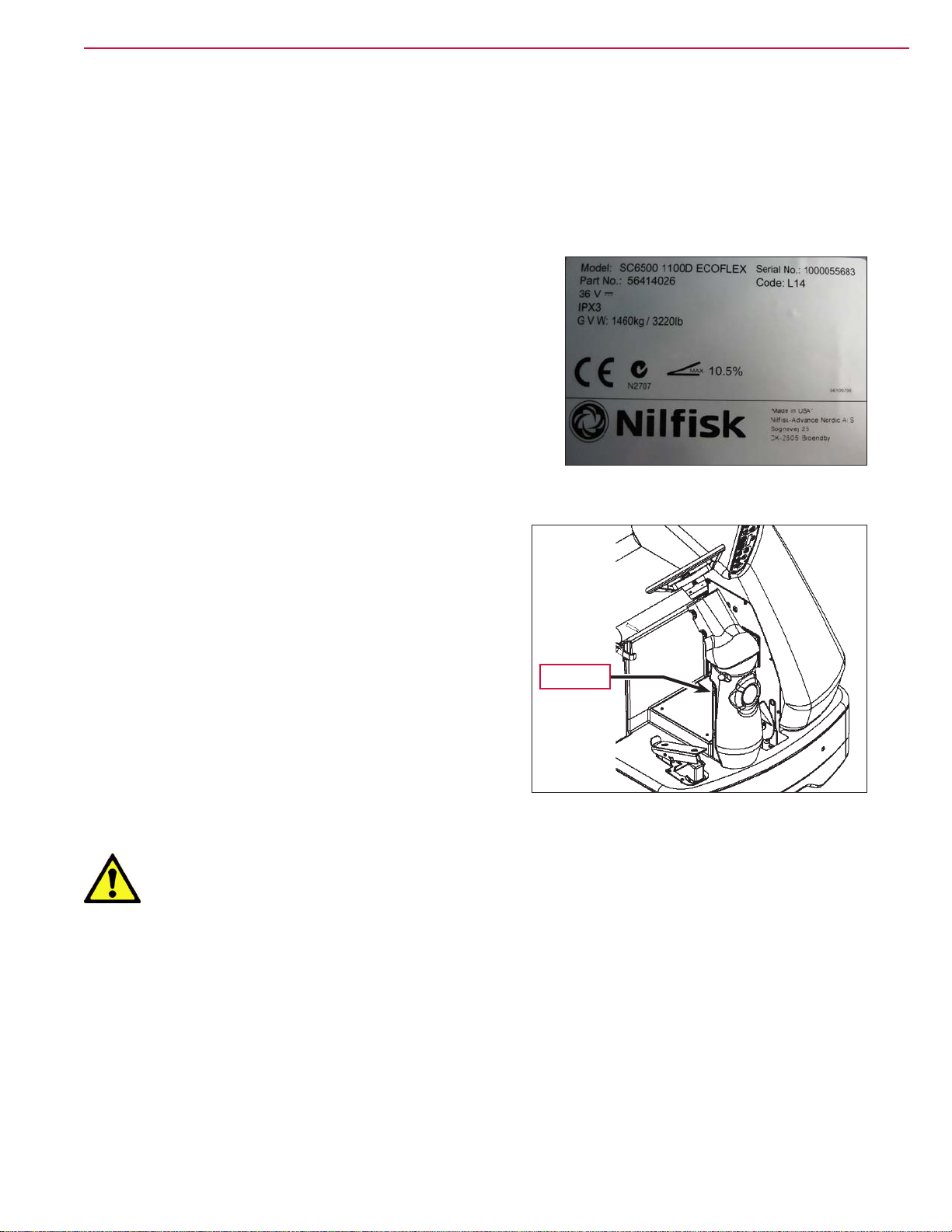
Nameplate
The Model Number and Serial Number of your machine
are shown on the machine nameplate. This information is
needed for selecting the correct technical documentation
and when ordering repair parts for the machine.
“Part No” on the label is equivalent to the machine
“Model Number”
Note that the Nameplate is attached to the rear of the
steering column.
Transporting the Machine
Caution! Before transporting the machine on an open truck or trailer, make sure that:
• The machine is tied down securely using approved tie down points.
• All access doors and covers are secured (tape or remove as needed).
• The battery/batteries are disconnected.
• Excessive strap force on rotomold plastic parts will cause permanent damage.
Nameplate
Page 11
™
General Information 11Service Manual – SC6500
Towing
Caution! If the machine must be towed or pushed, make sure the Master On/Off Key Switch is
in the Off position. Do not move the machine faster than a normal walking pace (2-3
mph, 3-5 kph) and for short distances only.
Note: Disconnecting the wheel drive motor wiring connector will make a disabled machine easier
to push.
Caution and Warning Symbols
Advance uses the symbols below to signal potentially dangerous conditions. Read this information carefully
and take the necessary steps to protect personnel and property.
Danger! Is used to warn of immediate hazards that will cause severe personal injury or death.
Warning! Is used to call attention to a situation that could cause severe personal injury.
Caution! Is used to call attention to a situation that could cause minor personal injury or
damage to the machine or other property.
Read all instructions before using.
General Safety Instructions
Specic Cautions and Warnings are included to warn you of potential danger of machine damage or bodily
harm.
Warning!
• This machine is to be used only by correctly trained and authorized persons.
• Avoid sudden stops while on ramps or inclines when the tanks are full. Avoid abrupt sharp
turns. Use low speed down hills. Clean only while ascending (driving up) the ramp.
• Keep sparks, flame and smoking materials away from batteries. Explosive gases are vented
during normal operation.
• Charging the batteries produces highly-explosive hydrogen gas. Charge batteries only in
well-ventilated areas, away from open flame. Do not smoke while charging the batteries.
• Remove all jewelry when working near electrical components.
Page 12

™
General Information 12Service Manual – SC6500
• Turn the key switch off (O) and disconnect the batteries before servicing electrical
components.
• Never work under a machine without safety blocks or stands to support the machine.
• Do not dispense flammable cleaning agents, operate the machine on or near these agents, or
operate in areas where flammable liquids exist.
• Only use the brushes provided with the machine or those specified in the instruction manual.
The use of other brushes may impair safety.
Caution!
• This machine is not approved for use on public paths or roads.
• This machine is not suitable for picking up hazardous dust.
• Do not use scarifier discs and grinding stones. Advance will not be held responsible for any
damage to floor surfaces caused by scarifiers or grinding stones. (This can also damage the
brush drive system.)
• When operating this machine, ensure that third parties, particularly children, are not
endangered.
• Before performing any service function, carefully read all instructions pertaining to that
function.
• Do not leave the machine unattended without first turning the key switch off (O), removing
the key and applying the parking brake.
• Turn the key switch off (O) and remove the key before changing the brushes, and before
opening any access panels.
• Take precautions to prevent hair, jewelry or loose clothing from becoming caught in moving
parts.
• Use caution when moving this machine in below-freezing temperature conditions. Any
water in the solution, recovery or detergent tanks, or in the hose lines could freeze, causing
damage to valves and fittings. Drain the tanks and purge with windshield washer fluid.
• The batteries must be removed from the machine before the machine is scrapped.
The disposal of the batteries should be done safely and in accordance with your local
environmental regulations.
Page 13
™
• Do not use on surfaces having a gradient exceeding that marked on the machine.
• All doors and covers are to be positioned as indicated in the instruction manual before using
the machine.
Caution! Do not pressure-wash the operator control panel, circuit breaker panel or any
electrical areas of the machine.
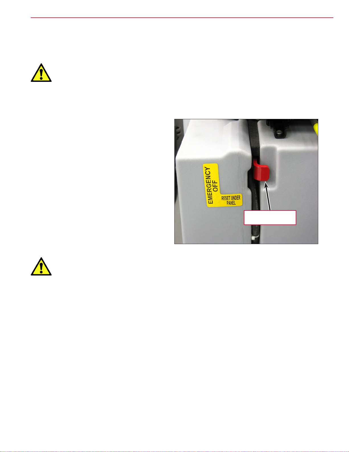
Emergency-stop Switch/Battery Disconnect
The Emergency-stop/Battery Disconnect is the red
lever located to the right of the Operator’s seat. In
the event of an emergency, press the Emergency-
stop/Battery Disconnect
the machine) to disconnect the battery from the
machine. This will stop all machine functions.
in (toward the rear of
General Information 13Service Manual – SC6500
Save These Instructions
Emergency-stop/
Battery Disconnect
Page 14

™
Technical Specifications (As Installed and Tested On The Unit)
Advance Brand SC6500 Models
General Information 14Service Manual – SC6500
Model (with and without
EcoFlex)
Model No. 56414010
Voltage, Batteries V 36V 36V 36V
Battery Capacity (max) Ah 450 450 450
Protection Grade IPX3 IPX3 IPX3
Sound Pressure Level
IEC 60335-2-72: 2002 Amend.
1:2005, ISO 11201
Sound Pressure level - KpA (IEC
60335-2-72, ISO 11201) Uncertainty
Gross Weight* - Cylindrical lbs / kg 3325 / 1508 3365 / 1526 3410 / 1547
Transportation Weight** -
Cylindrical
Gross Weight* - Disc lbs / kg 3220 / 1460 3270 / 1483 3320 / 1506
Transportation Weight** - Disc lbs / kg 2792 / 1266 2842 / 1289 2892 / 1312
Maximum Wheel Floor Loading
(center front)
Maximum Wheel Floor Loading
(right rear)
Maximum Wheel Floor Loading (left
rear)
Vibrations at the Hand Controls
(ISO 5349-1)
Vibrations at the Hand Controls
(ISO 5349-1) Uncertainty
Vibrations at the Seat (EN 1032) m/s2 <0.35m/s2 <0.35m/s2 <0.35m/s2
Vibrations at the Seat
(EN 1032) Uncertainty m/s2 0.035m/s2 0.035m/s2 0.035m/s2
Gradeability Transport 16% (9°) 16% (9°) 16% (9°)
Gradeability Cleaning 10.5% (6°) 10.5% (6°) 10.5% (6°)
Machine Length inch / cm 73.5 / 187
Machine Height
Machine Height (w/overhead guard) inch / cm 84 / 213
Machine Width at Rollers -
Cylindrical
Machine Width at Rollers - Disc inch / cm 42.5 / 108 51.5 / 131 52.5 / 133
Machine Width with Squeegee inch / cm 49 / 125 “F” 54 / 137 “G” 57 / 145 “H”
Minimum Aisle Turn Width inch / cm 84 / 214
dB(A)/20µPa 70 70 70
dB(A) 3.0 3.0 3.0
lbs / kg 2897 / 1314 2937 / 1332 2982 / 1353
psi / kg/cm2 116 / 8.15 116 / 8.15 116 / 8.15
psi / kg/cm2 81 / 5.69 81 / 5.69 81 / 5.69
psi / kg/cm2 86 / 6.04 86 / 6.04 86 / 6.04
m/s2 <1.12m/s2 <1.12m/s2 <1.12m/s2
m/s2 .11 m/s2 .11 m/s2 .11 m/s2
inch / cm 58.5 / 148.6
inch / cm 47.5 / 121 53.5 / 136 55.5 / 141
40C 45C 48C
40D 45D 48D
56414014
56414011
56414012
56414013
56414015
56414016
56414017
56414018
56414019
56414020
56414021
Page 15

™
General Information 15Service Manual – SC6500
Model (with and without
EcoFlex)
Model No. 56414010
40C 45C 48C
40D 45D 48D
56414014
56414011
56414012
56414013
56414015
56414016
56414017
56414018
56414019
56414020
56414021
Solution Tank Capacity Gallon / L 70 / 265
Recovery Tank Capacity Gallon / L 70 / 265
Transport Speed (Fwd. Maximum) mph / kph 6.0 / 9.5
Transport Speed (Rev. Maximum) mph / kph 3.0 / 5.0
Battery Compartment Size
(approximate)
Height (maximum) inch / cm 19 / 48.2
Width (maximum) inch / cm 20 / 50.8
Length (maximum) inch / cm 31.75 / 80.6
Scrub brush size
Outside Scrub Brush Diameter -
inch / cm 8.5 / 21.6
Cylindrical (inside core is 5 in / 12.7
cm)
Scrub Brush Length - Cylindrical
inch / cm 38.37 / 97.4
(two brushes per machine)
Brush Diameter - Disc inch / cm (Quantity of 2)
20 / 50.8
(Quantity of 3)
at 16 / 40.6
(Quantity of 3)
at 17 / 43
Scrub Brush Speed Cylindrical RPM 630 630 630
Scrub Brush Speed Disc RPM 240 225 225
Brush Motor Power hp / kW 40C - 2 x
1.5/1.13
45C - 2 x
1.5/1.13
48C - 2 x
1.5/1.13
40D - 1 x
3.0/2.24
45D - 3 x 1.5 /
1.13
48D - 3 x
1.5/1.13
Hopper Capacity - Cylindrical ft3 / L 0.40 / 11 0.44 / 12.5 0.50 / 14
Cleaning Path Width (scrubbing
inch / cm 40 / 101 45 / 114 48 / 122
path)
Sweeping Path with side brooms -
inch / cm 57 / 145
Cylindrical
Vacuum Motor hp / kW 0.8 / 0.6 - dual vac optional
Waterlift in / cm Single Vac - 64 / 163, Dual Vac - 67/170
Propulsion System Variable speed AC brushless drive
Propel motor (peak) hp / kW 3.0 / 2.25
*Gross Weight: Standard machine without options, full solution tank and empty recovery tank, with
removable scrub brushes and batteries installed.
Page 16

™
General Information 16Service Manual – SC6500
**Transportation Weight: Standard machine without options, empty solution and recovery tanks, with
batteries installed and no operator.
Nilfisk Brand SC6500 Models
Model (with and without EcoFlex) 1100C 1300C
. 1100D 1300D
Model No 56414023
56414022
Voltage, Batteries V 36V 36V
Battery Capacity Ah 480 480
Protection Grade IPX3 IPX3
Sound Pressure Level
dB(A)/20µPa 70 70
IEC 60335-2-72: 2002 Amend. 1:2005, ISO
11201
Sound Pressure level - KpA
dB(A) 3.0 3.0
56414025
56414024
(IEC 60335-2-72, ISO 11201) Uncertainty
Gross Weight* - Cylindrical lbs / kg 3325 / 1508 3410 / 1547
Transportation Weight** - Cylindrical lbs / kg 2897 / 1314 2982 / 1353
Gross Weight* - Disc lbs / kg 3220 / 1460 3320 / 1506
Transportation Weight** - Disc lbs / kg 2792 / 1266 2892 / 1312
Maximum Wheel Floor Loading (center
psi / kg/cm2 116 / 8.15 116 / 8.15
front)
Maximum Wheel Floor Loading (right rear) psi / kg/cm2 81 / 5.69 81 / 5.69
Maximum Wheel Floor Loading (left rear) psi / kg/cm2 86 / 6.04 86 / 6.04
Vibrations at the Hand Controls (ISO 5349-1)m/s2 <1.12m/s2 <1.12m/s2
Vibrations at the Hand Controls (ISO 5349-
m/s2 .11 m/s2 .11 m/s2
1) Uncertainty
Vibrations at the Seat (EN 1032) m/s2 <0.35m/s2 <0.35m/s2
Vibrations at the Seat (EN 1032)
m/s2 0.035m/s2 0.035m/s2
Uncertainty
Gradeability - Transport 16% (9°) 16% (9°)
Gradeability - Cleaning 10.5% (6°) 10.5% (6°)
Machine Length inch / cm 73.5 / 187
Machine Height inch / cm 58.5 / 148.6
Machine Height (w/overhead guard) inch / cm 84 / 213
Machine Width at Rollers - Cylindrical inch / cm 47.5 / 121 55.5 / 141
Machine Width at Rollers - Disc inch / cm 42.5 / 108 52.5 / 133
Machine Width with Squeegee inch / cm 49 / 125 “F” 57 / 145 “H”
Minimum Aisle Turn Width inch / cm 84 / 214
Solution Tank Capacity Gallon / L 70 / 265
Recovery Tank Capacity Gallon / L 70 / 265
Transport Speed (Fwd. Maximum) mph / kph 6.0 / 9.5
Transport Speed (Rev. Maximum) mph / kph 3.0 / 5.0
Page 17

™
General Information 17Service Manual – SC6500
Model (with and without EcoFlex) 1100C 1300C
. 1100D 1300D
Model No 56414023
56414022
56414025
56414024
Battery Compartment Size (approximate)
Height (maximum) inch / cm 19 / 48.2
Width (maximum) inch / cm 20 / 50.8
Length (maximum) inch / cm 31.75 / 80.6
Scrub brush size
Outside Scrub Brush Diameter - Cylindrical
inch / cm 8.5 / 21.6
(inside core is 5 in / 12.7 cm)
Scrub Brush Length - Cylindrical (two
inch / cm 38.37 / 97.4
brushes per machine)
Brush Diameter - Disc inch / cm (Quantity of 2) 20
/ 50.8
(Quantity of 3) at
17 / 43
Scrub Brush Speed Cylindrical RPM 630 630
Disc RPM 240 225
Hopper Capacity - Cylindrical ft3 / L 0.40 / 11 0.50 / 14
Cleaning Path Width (scrubbing path) inch / cm 40 / 101 48 / 122
Sweeping Path with side brooms -
inch / cm 57 / 145
Cylindrical
*Gross Weight: Standard machine without options, full solution tank and empty recovery tank, with
removable scrub brushes and batteries installed.
**Transportation Weight: Standard machine without options, empty solution and recovery tanks, with
batteries installed and no operator.
Page 18
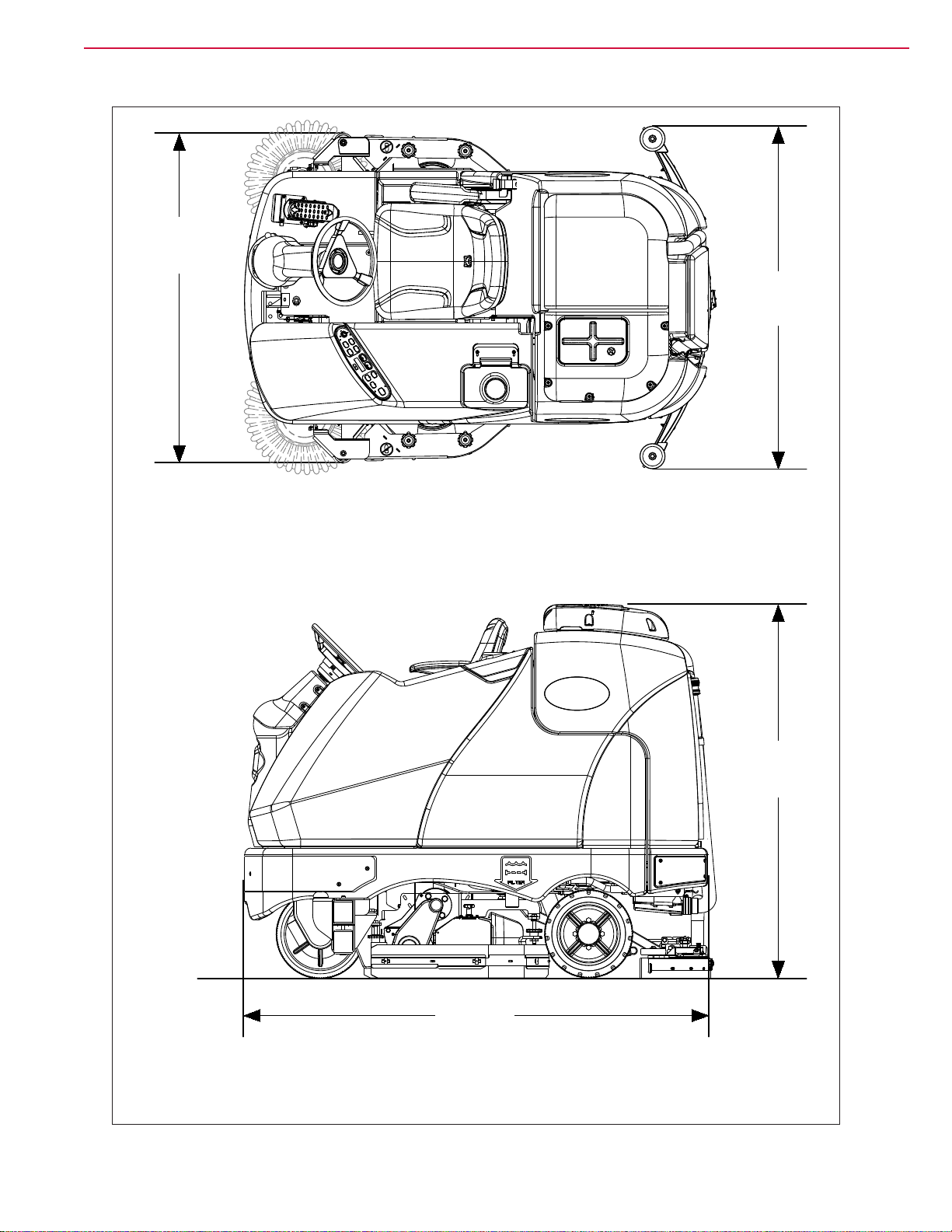
Dimensions
Machine Width
at Rollers
™
General Information 18Service Manual – SC6500
Width with
Squeegee
TOP VIEW
58.5
(148.6 cm)
73.5
(187 cm)
SIDE VIEW
Page 19
™
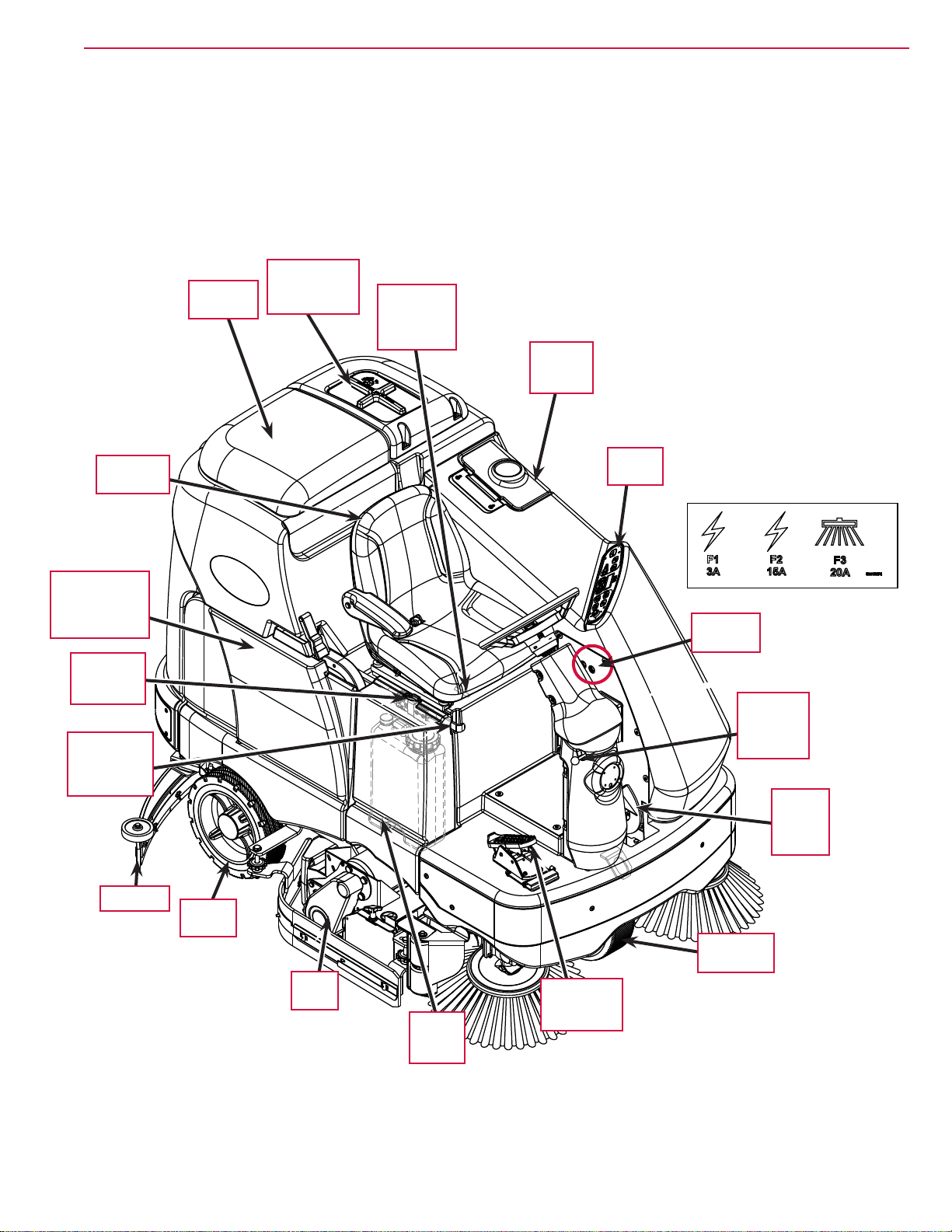
General Machine Overview
Major Machine Components
Vacuum Motor
Recovery
Tank Lid
Cover and
Filter
General Information 19Service Manual – SC6500
Operator’s
Seat
Adjustment
Lever
Solution
Tank Fill
Cover
Operator’s
Seat
Battery
Compartment
(underneath
recovery tank)
Machine
Battery
Connector
Emergencystop Switch/
Battery
Disconnect
Squeegee
Rear
Wheel
Scrub
Deck
Side
Access
Panel
Control
Panel
Circuit
Breakers
Steering
Wheel
Tilt/Adjust
Knob
Brake
Pedal/
Parking
Brake
Drive/Steer
Wheel
Drive Pedal,
Direction/
Speed
Page 20
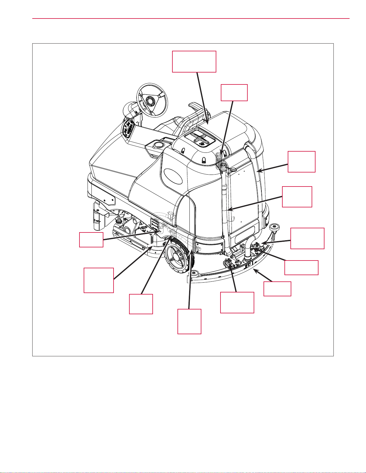
™
General Information 20Service Manual – SC6500
Recovery Tank
Cover
Assembly
Ball Float
Cage
Squeegee
Vacuum
Hose
Solution
Filter
Hopper
(cylindrical
models
only)
Solution
Shutoff
Valve
Recovery
Tank
Drain Hose
Squeegee
Height
Adjust Knob
Squeegee Tilt
Adjust Knob
Squeegee
Assembly
Squeegee
Height
Adjust Knob
Solution
Tank
Drain
Hose
Page 21
™
General Information 21Service Manual – SC6500
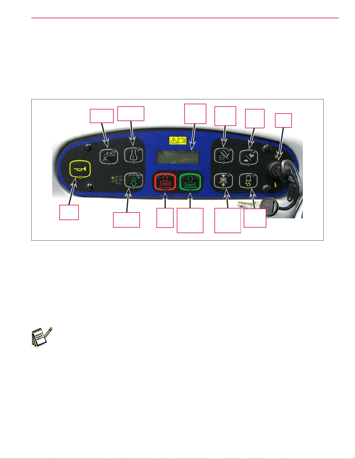
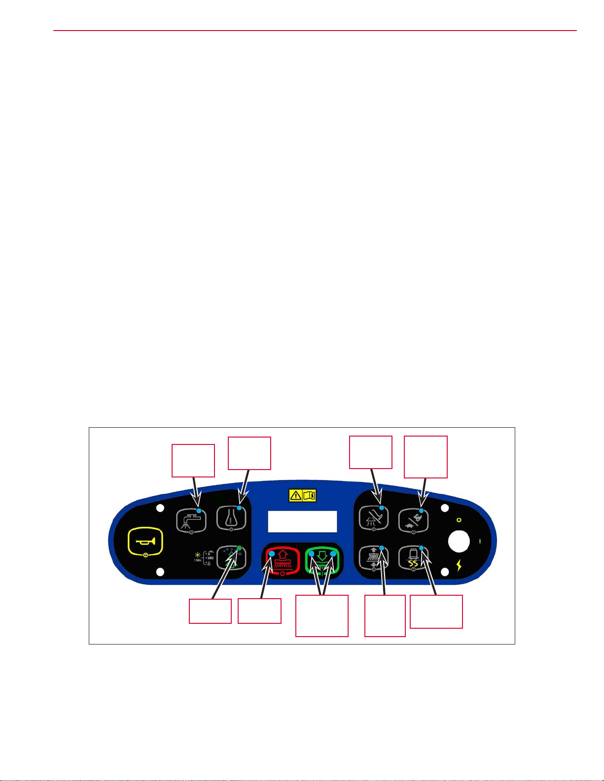
Control Panel
Switch and Button Functions
The controls on your rider scrubber were designed with one-touch operation in mind. For single-pass
scrubbing, the user can simply depress one switch and all systems on will be activated. For most single-pass
scrubbing operations, the operator should only need to use the middle switches on the control panel. These
are the red Scrub Off and the green Scrub On/Pressure Increase Switches.
Horn
Button
Solution
Switch
Detergent
Switch
Burst of
Power
Scrub
Off
Switch
Control
Panel
Display
Scrub On/
Pressure
Increase
Switch
Vacuum/
Wand
Switch
Side
Broom
On/Down
Switch
Scrub
Speed
Switch
Traction
Control
Switch
Key
Switch
• Key Switch – main power switch; controls the battery input to the machine’s main control board and the
wheel drive speed control.
• Scrub On/Pressure Increase Switch – functions as follows:
If the scrub system is off, pressing this switch once will put the machine into the Auto Scrub mode. The
following will occur:
– The scrub system will be enabled with the scrub pressure set to the #1 normal setting.
Note: Press the switch twice for #2 heavy scrub setting, and three times for the #3 extreme scrub
setting. Pressing the switch a fourth time will return the system to the normal scrub setting.
– The scrub deck and squeegee will automatically be lowered. On cylindrical models equipped with side
brooms, the side brooms will be lowered.
– The vacuum system will be enabled.
– The solution and detergent systems will be enabled. Note that both the solution and detergent ow
rates will correspond to the selected scrub pressure mode.
– As soon as the drive pedal is moved from its neutral position, the scrub brushes and side brooms (if
installed) will start turning, and the solution, detergent and vacuum systems will switch on.
Page 22

™
General Information 22Service Manual – SC6500
◦ If the direction is forward, the solution and detergent ow will also start automatically.
◦ If the direction is reverse, the solution and detergent ow will be stopped and the squeegee will be
raised just enough to clear the oor surface.
Note: The solution, vacuum and detergent systems are automatically enabled when the Scrub On
Switch
is pressed to put the machine into the Auto Scrub mode. Any individual system can
be toggled off and on by simply pressing the corresponding system switch at any time during
scrubbing.
If the machine is already scrubbing, pressing the Scrub On/Pressure Increase Switch will increase the
scrub pressure to the next higher setting (toggling from regular to heavy, heavy to extreme, then back to
normal). The Scrub Pressure Indicator will show the selected scrub pressure (one, two or three bars) in the
Control Panel Display.
• Scrub Off Switch – Pressing this switch when the machine is in the scrub mode will cause the following to
occur:
– The scrub brushes will turn off and the scrub deck will be raised to the up position. On cylindrical
models equipped with side brooms, the side brooms will shut off and be raised.
– The solution and detergent ow will be stopped.
– Once forward machine motion stops, the vacuum/wand switch indicator light will start to blink. After
a user-programmable time delay, the squeegee will be raised and the vacuum motors will shut off.
Pressing the switch a second time before the vacuum time delay is complete will raise the squeegee
and turn off the vacuum motors immediately.
• Solution Switch – functions as follows:
– If the scrub system is off, pressing and holding this switch will switch on the solution ow to pre-
wet the oor. The solution ow will stop when the switch is released. Note this must be done prior to
pressing the Scrub On Switch and putting the machine into the Auto Scrub mode.
– If the machine is in the Auto Scrub mode, pressing this switch will disable the solution system. This is
used if you wish to scrub without adding additional solution to the oor.
– If the machine is in the Auto Scrub mode, you can press and hold the Solution Switch to actuate the
solution ow override function. This override function allows you to select a different solution ow rate
without changing the scrub pressure. Note that the machine is programmed for two additional higher
solution ow rates plus the three normal default ow rates, for a total of ve solution ow rates.
To actuate the solution ow override function, press and hold the Solution Switch for three seconds until
the Solution System Indicator ashes, then release it. You’ll have three seconds to select the desired
solution ow rate by pressing the Solution Switch. The Solution Flow Indicator will show the selected
solution ow rate (one through ve bars) in the Control Panel Display. Note that if any scrub pressure
change is made while in the solution override mode, the solution ow will return to its default solution
ow rate.
• Detergent Switch – functions as follows:
– If the solution system is enabled, pressing this switch will toggle the detergent system off and on.
When the detergent system is on, the detergent pumps will be activated at a specic rate when the
drive pedal is actuated. The detergent pump will turn off when the drive pedal is in neutral or reverse.
Page 23

™
General Information 23Service Manual – SC6500
– If the solution system is off, the detergent pump will not turn on.
• Vacuum/Wand Switch – functions as follows:
– If the machine is in the Auto Scrub mode, pressing this switch once will raise the squeegee. The
vacuum motors will run for a short time delay, then shut off. If you press the switch twice, the vacuum
motors will shut off immediately. This is used if you wish to double-scrub (scrub without recovering the
solution).
– If the scrub system is off, the Vacuum/Wand Switch functions differently depending on whether the
seat switch is open (no operator in the seat) or closed (operator in the seat).
◦ If the operator is in the seat, pressing the switch will lower the squeegee and switch on the vacuum
motors. When the machine is moved into reverse, the squeegee will be raised, then lowered when
the machine is again moved forward. This mode is used to pickup water from the oor without
scrubbing or adding solution.
◦ If the operator is not in the seat, pressing the switch will toggle the vacuum motors on and off
to allow use of the vacuum wand. In this mode, the squeegee will not move up or down and the
recovery tank full indicator is ignored.
• Scrub Speed Switch – When the machine is operating in any one of its scrub settings, the machine’s travel
speed is reduced to 80 percent of the maximum transport speed pre-programmed into the speed controller.
Pressing the Scrub Speed Switch overrides the 80 percent of transport speed limit and increases the scrub
speed to 100 percent of transport speed.
• Traction Control Switch – regulates the drive wheel motor torque to minimize drive wheel slippage in
limited traction conditions.
• Side Broom On/Down Switch – lowers and raises the side brooms (only functional on cylindrical models
equipped with side brooms). Note that when the scrub system is switched on, the side brooms are lowered
to the same position they were in when the scrub system was last turned off (auto memory operating
position).
Note: You can raise or lower the side broom height to maintain the correct broom contact patterns
and compensate for normal broom wear. Refer to the Sweep System, Side Broom section for
instructions on setting the side broom height.
• Burst of Power Button – The Burst of Power Button functions differently depending on whether the EcoFlex™
mode is set to Mode 1 or Mode 2. (Also refer to the Control System/Main Programming Options/
EcoFlex™ Mode Selection section.) Note that in Mode 1 the detergent concentration is displayed as a
ratio. In Mode 2 the detergent concentration is displayed as a percent.
– In EcoFlex™ Mode 1, the minimum detergent concentration is displayed as a ratio. Pressing the Burst of
Power Button
in Mode 1 will do the following:
◦ The detergent ratio will change to the maximum concentration programmed ratio. (Also refer to the
Solution System/Maintenance and Adjustments/To Program the Detergent Ratio section.)
◦ The scrub pressure will increase to the next highest pressure.
◦ The solution ow rate will increase to the next highest level.
After 60 seconds, or after you press the Burst of Power Button again, the detergent ratio will revert
to the minimum concentration ratio, and the scrub pressure and solution rate will return to their
previous settings.
Page 24
™
General Information 24Service Manual – SC6500
– In EcoFlex™ Mode 2, the minimum detergent concentration is displayed as a percent.. Pressing the
Burst of Power Button in Mode 2 will do the following:
◦ The detergent ratio will change to the maximum concentration programmed percentage. (Also refer
to the Solution System/Maintenance and Adjustments/To Program the Detergent Ratio section.)
◦ The scrub pressure will increase to the next highest pressure.
◦ The solution ow rate will increase to the next highest level.
After 60 seconds, or after you press the EcoFlex
™
Button again, the detergent ratio will revert to the
programmed ratio, and the scrub pressure and solution rate will return to their previous settings.
• Horn Button – sounds the horn when pressed.
• Control Panel Display – displays the various icons that indicate scrub pressure, solution ow rate,
detergent ratio, battery charge state and a recovery tank full condition. The display also shows any error
conditions detected by the main control board.
Control Panel Indicators
In general the following guidelines apply to the control panel indicators:
• When the key switch is rst turned on all of the blue or green control panel indicator lights will turn on
for one second for an operational test.
• A light indicator means that a system is on and running, or has been enabled and is ready to switch on
when the drive pedal is moved into forward or reverse.
• The indicators will be off when the system is disabled or switched off.
Solution
System
Indicator
Detergent
System
Indicator
Vacuum/
Wand
Indicator
Maximum
Scrub
Speed
Indicator
EcoFlex
Indicator
Scrub Off
Indicator
Scrub On/
Scrub Mode
Select
Indicators
Side
Broom
On/Down
Indicator
Traction
Control
Indicator
Page 25

™
General Information 25Service Manual – SC6500
• Scrub On/Scrub Mode Select Indicator:
– The left side indicator will light when the normal scrub mode is selected.
– The right side indicator will light when the heavy scrub mode is selected.
– Both the right and left indictors will light when the extreme scrub mode is selected.
– Both the right and left indictors will be off when the scrub system is off.
• Scrub Off Indicator:
– The indicator will light to indicate that the scrub system is off and is ready to be activated.
– The indicator will be off when the scrub system is enabled and/or switched on.
• Solution System Indicator:
– The indicator will light when the solution system is enabled and/or is switched on.
– The indicator will be off when the solution system is off.
– The indicator will ash when the solution tank (liquid level) oat switch senses a low solution level.
• Detergent System Indicator:
– The indicator will light when the detergent system is enabled and/or is switched on.
– The indicator will be off when the detergent system is off.
Note: The control board automatically recognizes that the machine has an operational detergent
system through its wiring harness connection.
• Vacuum/Wand Indicator:
– The indicator will light when the vacuum system is enabled and/or is switched on.
– The indicator will be off when the vacuum system is off.
– The indicator will ash when the vacuum system is operating in the time delay shutdown mode
(normally ve to 10 seconds).
• Maximum Scrub Speed Indicator:
– The indicator will light when the maximum 100% transport speed during scrubbing is enabled.
– The indicator will be off when normal scrub speed is enabled.
• Traction Control Indicator:
– The indicator will light when the traction control mode is enabled.
– The indicator will be off when the traction control mode is disabled.
• Side Broom On/Down Indicator:
– The indicator will be on when the side brooms are in the down working position, enabled and switched
on.
Page 26
™
General Information 26Service Manual – SC6500
– The indicator will be off when the scrub system is switched off and the brooms are in the raised
position.
• EcoFlex Indicator:
– The (green) indicator will be on when the EcoFlex™ low-concentration detergent mode is enabled.
– The (green) indicator will ash when the EcoFlex™ burst of power mode is enabled.
– The (green) indicator will be off when the EcoFlex™ full-concentration detergent mode is enabled.
Note: When the recovery tank becomes full (when in the auto scrub mode), the vacuum motors and
all other systems shut off except the drive motor. The LCD on the dash panel will display the
full tank icon.
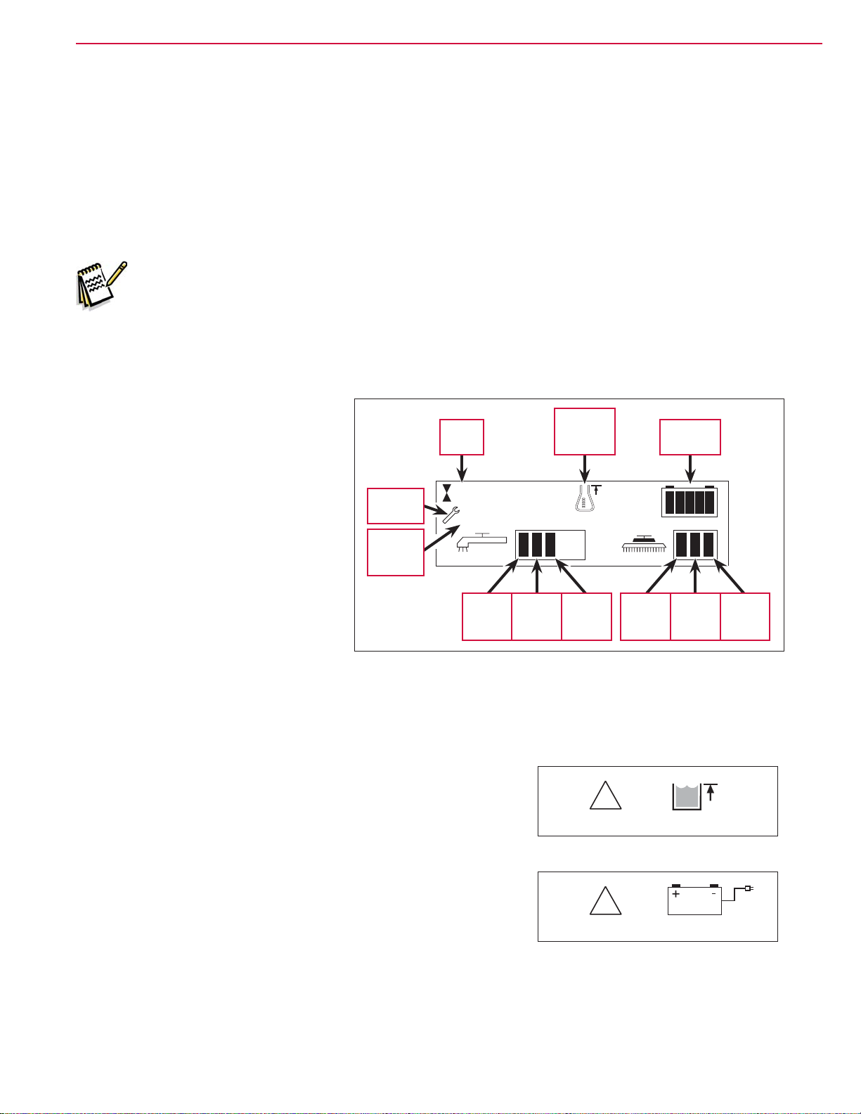
Control Panel Display
The control panel display is a liquid
crystal display (LCD) that shows the
hour meter, battery charge indicator,
solution ow rate and scrub pressure.
Hour
Meter
Detergent
System
Indicator
Battery
Indicator
If the detergent system is enabled, the
display will also show the detergent
system indicator and the current
detergent/solution ratio.
If an A2 Control Board error occurs,
the display will show a wrench icon
Error
Indicator
Error
Code
Number
Ø .4
29
Ratio
to indicate an error, and display a
two-digit error code number. If more
than one error exists, the display will
sequence through the error codes at
Regular
Solution
Flow
Heavy
Solution
Flow
Extreme
Solution
Flow
Normal
Scrub
Pressure
Pressure
one-second intervals. (Refer to the
Control System section for a list of the
A2 Control Board error codes.)
Heavy
Scrub
Extreme
Scrub
Pressure
Caution Displays
If the recovery tank is full, the display will show a caution symbol
and the tank full icon.
If the battery charge level falls to a critical level, the display will
show a caution symbol and the battery-low icon.
!
!
Page 27
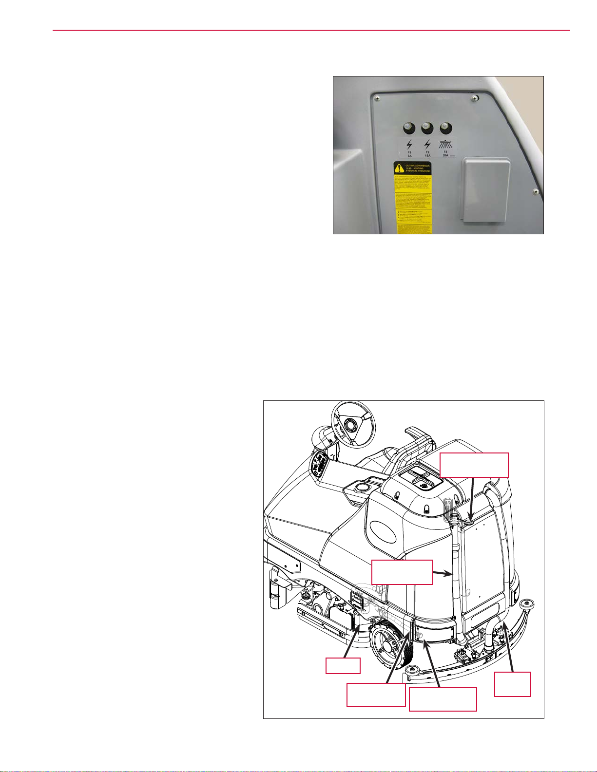
™
Circuit Breakers
The machine circuit breakers are located on the panel to
the left of the Operator seat.
General Maintenance
Maintenance After Use
General Information 27Service Manual – SC6500
1. When nished scrubbing, press the Scrub Off Switch. This will automatically raise the scrub deck and
squeegee, and switch off the solution, detergent and vacuum systems.
2. Drive the machine to a service area for daily maintenance, and check the machine for any additional
maintenance or service that may be needed.
3. To empty and clean the solution tank:
a. Remove the Solution Tank Drain
Hose
from its storage clamp.
b. Direct the Solution Tank Drain Hose
to a designated disposal site and
remove the Solution Tank Drain
Hose Plug
.
Recovery Tank
Drain Hose Plug
c. Rinse the tank with clean water.
4. To empty and clean the recovery tank:
a. Pull the Recovery Tank Drain Hose
from its storage area.
b. Direct the Recovery Tank Drain
Hose
to a designated disposal site
Recovery Tank
Drain Hose
and remove the Recovery Tank
Drain Hose Plug
. (Hold the end of
the Recovery Tank Drain Hose above
the water level in the tank to avoid
sudden, uncontrolled wastewater
ow.) The Recovery Tank Drain Hose
can be squeezed to regulate the
ow.
c. Rinse the recovery tank with clean
water.
Hopper
Solution Tank
Drain Hose
Solution Tank
Drain Hose Plug
Vacuum
Hose
Page 28

™
General Information 28Service Manual – SC6500
d. Inspect the Solution Tank Drain Hose, Recovery Tank Drain Hose and Vacuum Hose for wear or damage.
Replace the if kinked or damaged.
5. Remove the brushes or pad holders. Rinse the brushes or pads in warm water and hang up to dry.
6. Remove the squeegee, rinse it with warm water, then reinstall.
7. Remove the Hopper on cylindrical systems and clean thoroughly. You can remove the Hopper from either
side of the machine by removing the side skirt, tilting the Hopper up and away from housing, then
pulling the Hopper out.
8. Check the following maintenance schedule and perform any required maintenance before you store the
machine.
Maintenance Schedule
Maintenance Item Daily Weekly Monthly Yearly
Charge Batteries X
Check/Clean Tanks and Hoses X
Check/Clean/Rotate the Brushes/Pads X
Check/Clean the Squeegee X
Check/Clean Vacuum Shutoff Float X
Check/Clean the Vacuum Motor Foam Filter(s) X
Clean Hopper on Cylindrical System X
Check the Water Level in each Battery Cell X
Inspect Scrub Housing Skirts X
Inspect and Clean Solution Filter X
Check Foot/Parking Brake For Wear and Adjustment X
Clean Solution Dispensing Trough on Cylindrical System X
Purge Detergent System X
Side Broom Maintenance X
Lubrication - Grease Fittings X
* Check Carbon Brushes X
* Inspect the vacuum motor carbon brushes every 300 operating hours. Check the brush and drive motor
carbon brushes every 500 operating hours.
Note: Refer to the individual machine sections in this manual for more detail on maintenance and
service repairs.
9. Store the machine indoors in a clean, dry place. Keep the machine from freezing. Leave the tanks open
to air them out.
10. Turn the key switch off (O) and remove the key.
Caution! Do not pressure-wash the operator control panel, circuit breaker panel or any
electrical areas of the machine.
Page 29
™
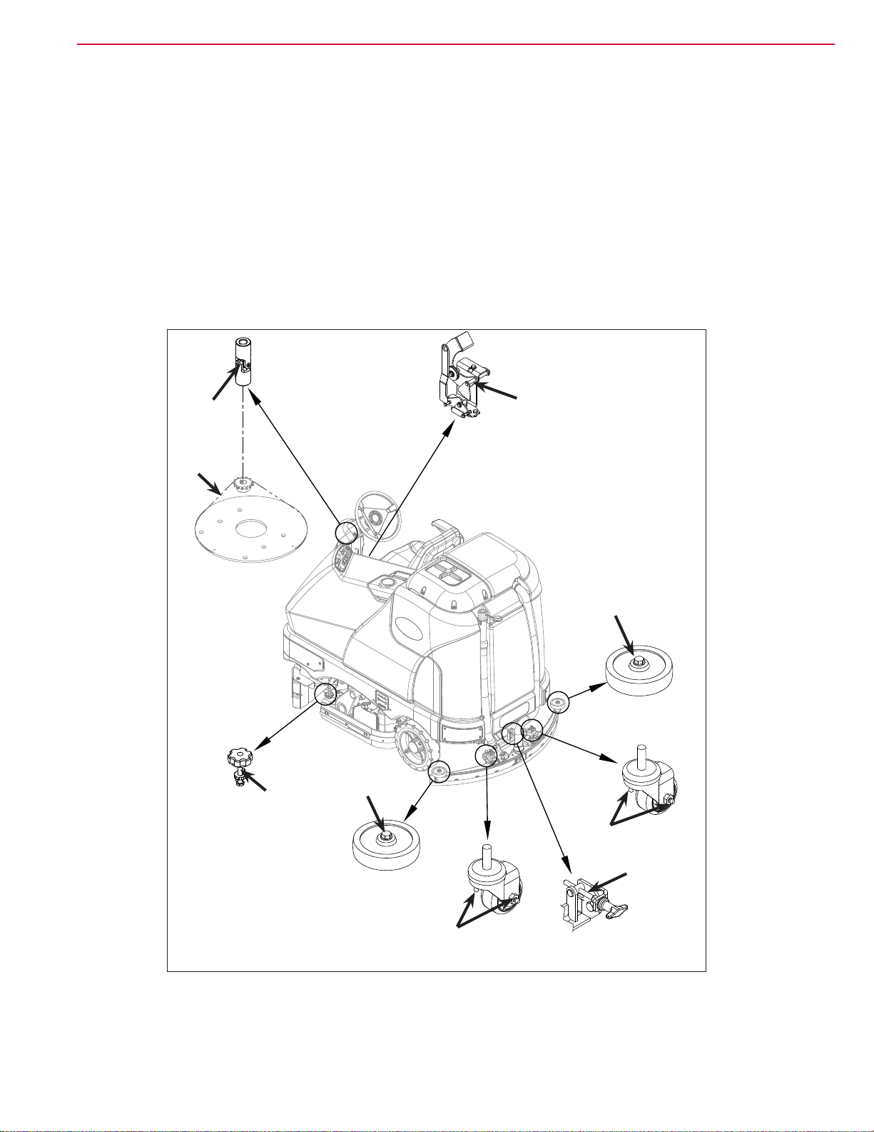
Machine Lubrication
Once a month:
General Information 29Service Manual – SC6500
• Steering Chain
• Pump a small amount of grease into each grease
tting on the machine as shown until grease
seeps out around the bearings.
• Apply light machine oil to the components shown.
Apply grease to:
• Squeegee Caster Wheel Axle and Pivot
• Steering Wheel Shaft Universal joint
Grease
Grease
• Squeegee mount angle adjustment knob threads
Apply light machine oil to:
• Squeegee tool end wheels
• Recovery Tank release latch
• Brake Pedal (parking brake) linkage
Lubrication Points
Oil
Grease or
Anti-seize
Oil
Oil
Grease
Grease or
Anti-seize
Grease
Page 30

™
PM Check List - SC6500
Customer _________________________________________________________
Address ___________________________________________________________
City ____________________________ ST _______________ Zip____________
Model _____________ Serial ______________________ Hours _____________
General Information 30Service Manual – SC6500
Defect Code
A needs adjustment
B binding
C dirty or contaminated
D damaged, bent or torn
L leaks
M missing
W worn out
Ref Operational Inspection Items OK Defect Codes
(Circle)
1 Steering A B W
2 Drive Pedal Operation (check for Fwd/Rev drive and any
neutral creep)
3 Seat Safety Switch (when operator stands up machine is to
stop)
4 Brakes (service and parking) A B W
5 Drive System Performance (reference Service Manual for
Curtis drive programmer speed changes)
6 Scrub System (Raise/Lower and auto scrubbing functions) A B
7 Scrub Brush Pressure Settings (see Service Manual
programming, 3 different modes)
8 Squeegee System (Raise/Lower and auto lift in reverse
function)
9 Vacuum Performance (sealed water lift 70” and 1-inch open
hole adapter 15 inches)
10 Solution Control (On/Off and ow volume Min/Max) A B L
11 Solution Control (On/Off and ow volume Min/Max) B D
12 Emergency Battery Disconnect Control Lever A B D
13 Side broom Sweep System, Raise/Lower and auto sweep
functions (cylindrical only)
14 Tilt Steering Mechanism and Seat D
15 Main Control Board Special Program Options (check all
applicable program settings); Example, Fault Recall Mode,
etc.
16 Battery Charger Operation D
17 Chemical Detergent System Functions C L
A B D
A D
noisy sluggish
A B
A B
C L W
A B D
Program as needed
Does
Not
Work
Page 31

Ref Visual Inspection Items Comments OK Defect Codes
(Circult)
18 Scrub Brushes, check for wear and rotate A B D W
19 Scrub Brush Motor(s) and disc machine
gearboxes
20 Scrub Brush Drive Belt, wear (cylindrical
only)
21 Scrub Brush Deck Actuator Motor A B D W
22 Brush Driver Plates (ex coupler and
retainer clips) (disc only)
23 Brush Idler Bearing Plate and Driver
(cylindrical only)
24 Scrub Deck Skirts A B W
25 Solution Solenoid Valve Inspect Poppet C L
26 Solution Tank, Delivery Hoses and Filter Clean Filter
27 Vacuum Motor Carbon Brushes Wear Limit 3/8” W
28 Vacuum Motor Cover Gasket and Filters Clean lter and
29 Vacuum Float Ball and Cage Assembly Clean Float C M
30 Recovery Tank Cover Gasket Air leaks C D L
31 Recovery Tank Drain Hose and Cap Flush C L
32 Squeegee Pick-Up Tool and Hose Back ush C L
33 Squeegee Blades (clean and rotate) A C D W
34 Squeegee Mount Wheels (lubricate) 4 Grease
35 Squeegee Lift Actuator Motor and Lifting
Bar
36 Battery Pack Condition (clean and water) Load Test C W
37 Front Drive Wheel Motor Carbon Brushes C W
38 Front Drive Tire Tread Wear W
39 Rear Brake Rotors and Disc Wear Adjust Free
40 Drive Pedal Linkage (neutral return) Hydroback
41 Steering Chain (lubricate and tension) 1/4” Deection A B C
42 Steering Column (knob and plunger
spring) also Universal Joint
43 Rear Wheels Tread and
44 Sweep Debris Hopper (cylindrical only) Rinse C
Carbon Brushes B L W
1000 hours then
every 500 hours
Screen
screen
Fittings
Play
Spring
Grease A D
bearings
A D W
D M
C W
C L
L W
A C W
A B D
A B W
A B
C W
Does
Not
Work
Work Completed By:____________________________
Date: __________________________________________
Acknowledged By:_______________________________
Date:____________________________________________
Page 32

™
Chassis System
Major Chassis Components
Chassis System 32Service Manual – SC6500
45 in / 48in /
1300mm models
only
Page 33

™
Control System 33Service Manual – SC6500
Control System
Functional Description
Overview
The control system consists of the A2 Control Board Assembly, the A3 Switch/Display Panel Assembly and
associated sensors and circuitry.
A2 Control Board Assembly
The A2 Control Board Assembly, sometimes referred to the
main controller, communicates with the Curtis A1 Speed
Controller
and the A3 Switch/Display Panel Assembly to
coordinate the operation of the various machine systems.
The A2 Control Board Assembly is fastened to the Electrical
Mount
behind the electrical panel cover assembly to the
left of the Operator seat.
A2 Control Board
Assembly
Electrical
Mount
One primary function of the A2 Control Board Assembly is
to position the scrub brushes relative to the oor surface
using a lift actuator motor. The A2 Control Board Assembly
continuously monitors the brush motor current draw to
maintain the desired scrub pressure on the oor.
Curtis A1
Speed
Controller
• If the brush motor current drops below the desired
range, the A2 Control Board Assembly switches on the
lift actuator motor to move the scrub deck downward
until the brush motor current draw is within the
correct range for the scrub pressure selected.
• If the brush motor current rises above the desired
range, the A2 Control Board Assembly switches on the
lift actuator motor to lift the scrub deck upward until
the brush motor current draw is again within the
correct range for the scrub pressure selected.
Note: Refer to the Scrub System section in this
manual for a complete explanation of
scrub deck operation.
A secondary function of the A2 Control Board Assembly is to detect any system failures and display the
corresponding error code on the display panel, or store it in the control board’s recall memory mode. The
error codes are used to help service technicians determine the fault and to guide in repairing a specic
system malfunction quickly.
Note: See the Troubleshooting section for further information.
The A2 Control Board Assembly also allows you to change program settings for a set of specic machine
functions. See the Main Control Programming Options section in this manual for further information.
Page 34

™
A3 Switch/Display Panel Assembly
The A3 Switch/Display Panel Assembly is the user
interface that includes the various system switches and
buttons, and the control panel display. The A3 Switch/
Display Panel Assembly sends the operator inputs via a
CAN BUS to the A2 Control Board Assembly.
Control System 34Service Manual – SC6500
Circuit Description
The A2 Control Board Assembly is connected by several inputs to battery negative:
The A2 Control Board Assembly gets positive battery voltage from two inputs:
• When the key switch, seat switch and battery interlock are closed, positive voltage is supplied to the A2
Control Board Assembly.
• When the key switch is closed, positive voltage is supplied to the coil side of contactor K5. When K5
contacts close, positive voltage is supplied to the A2 Control Board Assembly.
The A3 Switch/Display Panel Assembly gets voltage from two outputs on the A2 Control Board Assembly.
The A3 Switch/Display Panel Assembly communicates with the A2 Control Board Assembly via a CAN BUS
connection (CAN H and CAN L).
Main Control Programming Options
Fault Recall Mode
Whenever the A2 Control Board Assembly detects an electrical system error or fault, one or more error codes
are displayed and stored by the A2 Control Board Assembly. You can recall error codes (if any) from previous
machine operation for troubleshooting purposes, To recall stored error codes:
1. Turn the key switch off.
2. Press and hold the solution switch.
3. While holding the solution switch, turn the key switch on.
4. Continue to hold the solution switch until the solution system indicator turns on.
5. Release the solution switch. The solution system indicator turns off and the scrub off indicator will light.
The display will show a wrench icon indicating that you are in fault recall mode.
• If there are no previous error codes stored, the display will show the no-fault wrench icon
asking you to reset the machine (no fault). Skip to step 7.
• If error codes have been stored, the display will show the wrench icon and error number(s) next to the
wrench. If more than one error code is stored, the display will toggle through all the errors stored.
6. • If you want to save the codes, skip to step 7.
• To clear the stored error codes, press the scrub off switch. The display will now show key switch icon
asking you to reset the machine.
7. To exit the fault recall mode, turn the key switch off.
Page 35

™
To Select the Battery Used in the Machine
Note that the factory default is Standard (LVC = 31V)
1. Turn the key switch off.
2. Press and hold the scrub off switch.
3. While holding the scrub off switch, turn the key switch on.
4. Continue to hold the scrub off switch until the Scrub Off LED indicator turns on.
5. Release the switch. The display will now show BATTERY.
6. Press the scrub on switch to select the type of battery that is in the machine.
7. Press the scrub off switch to save the new setting and display the key switch icon.
8. Turn the key switch off. The new setting will be saved until changed again.
To Restore the Scrub Pressures to the Factory Default Settings
Control System 35Service Manual – SC6500
1. Turn the key switch off.
2. Press and hold the scrub on switch.
3. While holding the scrub on switch, turn the key switch on.
4. Continue to hold the scrub on switch until the display shows key switch icon. The factory default scrub
pressures have now been restored.
5. Turn the key switch off.
To Enable/Disable the Fault Detection
Note that the factory default for fault detection is OFF.
You can enable or disable “open circuit” fault detection with this setting. If the setting is set to “off” the
controller will still detect and set faults for over current conditions.
To turn the fault checking on or off:
1. Turn the key switch off.
2. Press and hold both the scrub off switch and solution switch.
3. While holding both switches, turn the key switch on.
4. Continue to hold both switches until both switch indicators turn on. The display will show a wrench icon
indicating fault detection mode.
5. Release both switches. The solution system indictor light will blink and the scrub off indicator will stay
on.
6. Press the solution switch to toggle the fault detection between enabled/on (wrench icon with no cross) or
disabled/off (wrench icon with cross).
7. Press the scrub off switch to save the new setting and display the key switch icon.
8. Turn the key switch off. The new setting will be saved until changed again.
Page 36

™
Control System 36Service Manual – SC6500
To Display the Control Board Revision Level
1. Turn the key switch off.
2. Press and hold both the scrub off switch and traction control switch.
3. While holding both switches, turn the key switch on.
4. Continue to hold both switches until the scrub off and traction control indicators light.
5. Release both switches. The scrub off and traction control indicators will switch off. The display will show
the MAIN REVISION of the A2 control board assembly, the DISPLAY REVISION of the A3 switch/display
panel assembly and the key switch icon.
6. Turn the key switch off.
Monitor Mode
The control system allows the ve machine settings listed below to be quickly checked in the monitor mode
to view the machine’s specic setup. To enter the monitor mode and view the current machine settings:
1. Turn the key switch off.
2. Press and hold the detergent switch.
3. While holding the detergent switch, turn the key switch on.
4. Continue to hold the detergent switch until the detergent system indicator switches on.
5. Release the detergent switch. The display
will show the following current machine
programmed settings:
• Scrub deck type and size,
• Detergent mode on/off,
• Fault detection on/off,
• Vacuum motor selection – VACUUM–SINGLE (one motor) or VACUUM–DUAL (two motors).
6. To exit the monitor mode, turn the key switch off.
Scrub Deck Down Time Adjustment
Note that the factory default deck down time is two seconds.
When scrub on switch is pressed, the control board will automatically lower the deck for two seconds. The
time that the deck is lowered is adjustable from one second to three seconds in 0.1-second increments.
To adjust the scrub deck down time:
1. Turn the key switch off.
2. Press and hold the scrub on and solution switches.
3. While holding both switches, turn the key switch on.
4. Continue to hold both switches until both switch indicators turn on.
Page 37

™
Control System 37Service Manual – SC6500
5. Release both switches. The display will now show a clock icon in the upper left corner with a number
indicating the scrub deck down time period.
6. Press the scrub on switch to increment the time period. Each press of the switch increments the scrub
deck down time 0.1 seconds. For example, the time will increment from 2.0 seconds to 2.1 seconds, and
so on. The deck down times range from 1.0 to 3.0 seconds.
7. Press the scrub off switch to save the new setting and display the key switch icon.
8. Turn the key switch off. The new setting will be saved until changed again.
Normal (Light) Scrub Setting Adjustment
Note that the factory default settings for the normal scrub setting are: Scrub pressure – one bar, Solution
ow rate – one bar.
The scrub pressure and solution ow rate for the normal scrub setting can be programmed to better suit a
particular application. This allows you to select a higher solution ow rate with normal scrub pressure, or
a normal solution rate with heavier scrub pressure, etc., as the normal scrub setting. To change the normal
scrub settings:
1. Turn the key switch off.
2. Press and hold the scrub on and scrub speed switches.
3. While holding both switches, turn the key switch on.
4. Continue to hold both switches until the scrub speed indicator turns on and the normal scrub on
indicator blinks.
5. Release both switches. The display will now show a scrub icon (either disc or cylindrical) with the
current scrub pressure setting.
6. Press the scrub on switch to increment the scrub pressure setting as shown by the number of bars in the
display.
7. Press the scrub off switch to save the new scrub pressure setting and move to the solution ow rate
setting. The display will now show the solution icon with gauge. The normal scrub indicator will stop
blinking and the solution system indicator will blink.
8. Press the solution switch to increment the solution ow rate as shown by the number of bars in the
display.
9. Press the scrub off switch to save the new solution ow rate setting and move to the detergent
concentration setting. The display will now show the detergent icon with a 0, + or – next to it. The
solution system indicator will stop blinking and the detergent indicator will blink.
10. Press the detergent switch to scroll through and select the 0, + or – character in the display.
• Selecting 0 will not change the detergent concentration in the detergent ratios.
• Selecting + will increase the detergent concentration in the detergent ratios by 10 percent.
• Selecting – will decrease the detergent concentration in the detergent ratios by 10 percent.
11. Press the scrub off switch to save the detergent concentration setting and display the key switch icon.
12. Turn the key switch off. The new settings will be saved until changed again.
Page 38

™
Control System 38Service Manual – SC6500
Heavy Scrub Setting Adjustment
Note that the factory default settings for the heavy scrub setting are: Scrub pressure – two bars, Solution
ow rate – two bars.
The scrub pressure and solution ow rate for the heavy scrub setting can be programmed to better suit
a particular application. This allows you to select a higher solution rate with heavy scrub pressure, or a
normal solution rate with heavy scrub pressure, etc., as the heavy scrub setting. To change the heavy scrub
settings:
1. Turn the key switch off.
2. Press and hold the scrub on and detergent switches.
3. While holding both switches, turn the key switch on.
4. Continue to hold both switches until the detergent indicator turns on and the heavy scrub indicator
blinks.
5. Release both switches. The display will now show a scrub icon (either disc or cylindrical) with the
current scrub pressure setting.
6. Press the scrub on switch to increment the scrub pressure setting as shown by the number of bars in the
display.
7. Press the scrub off switch to save the new scrub pressure setting and move to the solution ow rate
setting. The display will now show the solution icon with gauge. The solution system indicator will
blink.
8. Press the solution switch to increment the solution ow rate as shown by the number of bars in the
display.
9. Press the scrub off switch to save the new solution ow rate setting and move to the detergent
concentration setting. The display will now show the detergent icon with a 0, + or – next to it. The
solution system indicator will stop blinking and the detergent indicator will blink.
10. Press the detergent switch to scroll through and select the 0, + or – character in the display.
• Selecting 0 will not change the detergent concentration in the detergent ratios.
• Selecting + will increase the detergent concentration in the detergent ratios by 10 percent.
• Selecting – will decrease the detergent concentration in the detergent ratios by 10 percent.
11. Press the scrub off switch to save the detergent concentration setting and display the key switch icon.
12. Turn the key switch off. The new settings will be saved until changed again.
Extreme Scrub Setting Adjustment
Note that the factory default settings for the extreme scrub setting are: Scrub pressure – three bars, Solution
ow rate – three bars.
The scrub pressure and solution ow rate for the extreme scrub setting can be programmed to better suit
a particular application. This allows you to select a higher solution rate with extreme scrub pressure, or a
normal solution rate with extreme scrub pressure, etc., as the extreme scrub setting. To change the extreme
scrub settings:
1. Turn the key switch off.
2. Press and hold the scrub on and vacuum/wand switches.
Page 39

™
Control System 39Service Manual – SC6500
3. While holding both switches, turn the key switch on.
4. Continue to hold both switches until the vacuum/wand indicator turns on, and the normal and heavy
scrub indicators blink.
5. Release both switches. The display will now show a scrub icon (either disc or cylindrical) with the
current scrub pressure setting.
6. Press the scrub on switch to increment the scrub pressure setting as shown by the number of bars in the
display.
7. Press the scrub off switch to save the new setting and move to the solution ow rate setting. The display
will now show the solution icon with gauge. The normal and heavy scrub indicators will stop blinking
and the solution indicator will blink.
8. Press the solution switch to increment the solution ow rate as shown by the number of bars in the
display.
9. Press the scrub off switch to save the new solution ow rate setting and move to the detergent
concentration setting. The display will now show the detergent icon with a 0, + or – next to it. The
solution system indicator will stop blinking and the detergent indicator will blink.
10. Press the detergent switch to scroll through and select the 0, + or – character in the display.
• Selecting 0 will not change the detergent concentration in the detergent ratios.
• Selecting + will increase the detergent concentration in the detergent ratios by 10 percent.
• Selecting – will decrease the detergent concentration in the detergent ratios by 10 percent.
11. Press the scrub off switch to save the detergent concentration setting and display the key switch icon.
12. Turn the key switch off. The new settings will be saved until changed again.
Scrub Speed Switch Lockout
Note that the factory default setting for the scrub speed switch is FAST/SLOW - ENABLE.
The control system is programmed to limit the maximum travel speed while scrubbing to a value less
than that allowed when driving and not scrubbing. Pressing the scrub speed switch on the control panel
will override this speed limiting feature and allow scrubbing at a the higher speed. If you wish to prevent
scrubbing at this faster speed, you can disable the scrub speed switch override feature. To disable the scrub
speed switch override feature:
1. Turn the key switch off.
2. Press and hold the scrub speed switch.
3. While holding the scrub speed switch, turn the key switch on.
4. Continue to hold the scrub speed switch until the scrub speed and scrub off indicators both turn on.
5. Release the scrub speed switch. The scrub speed indictor light will blink.
6. Press the scrub speed switch to enable or disable the scrub speed switch override feature. FAST/SLOW
- ENABLE
means that the high-speed scrub feature is turned on. FAST/SLOW - DISABLE means that the
high-speed scrub feature is turned off.
7. Press the scrub off switch to save the setting and display the key switch icon.
8. Turn the key switch off. The new setting will be saved until changed again.
Page 40

™
Control System 40Service Manual – SC6500
Detergent System Selection Mode
1. Turn the key switch off.
2. Press and hold the scrub off switch and the detergent switch.
3. While holding both switches, turn the key switch on.
4. Continue to hold both switches until both switch indicators turn on.
5. Release both switches. The scrub off indicator will stay lit and the detergent system indicator will blink.
The display will now show a detergent bottle in the upper left corner indicating the detergent selection
mode.
6. Press the detergent switch to select between a normal detergent bottle icon indicating that the detergent
system is activated, or a detergent bottle with a cross through it indicating that the detergent system is
not activated.
7. Press the scrub off switch to save the new setting and display the key switch icon.
8. Turn the key switch off. The new setting will be saved until changed again.
EcoFlex™ Mode Selection
Note that the factory default setting for the EcoFlex™ Mode is OFF.
1. Turn the key switch off.
2. Press and hold the EcoFlex™ button.
3. While holding the button, turn the key switch on.
4. Continue to hold the button for two seconds until the EcoFlex™ and scrub off indicators turn on.
5. Release the EcoFlex™ button. The display will now show the ECOFLEX MODE/
OFF
, ECOFLEX MODE/MODE 1 and ECOFLEX MODE/MODE 2 menu.
6. Press the EcoFlex™ button to scroll through the menu and select the desired
ECOFLEX MODE. On the SC6500, there is no difference in machine operation
whether Mode 1 or Mode 2 is selected.
ECOFLEX MODE
OFF
ECOFLEX MODE
MODE 1
ECOFLEX MODE
MODE 2
7. Press the scrub off switch to save the setting and display the key switch icon.
8. Turn the key switch off. The new setting will be saved until changed again.
Vacuum Motor Configuration Option
Note that the factory default setting for the vacuum motor conguration is SINGLE (one vacuum motor).
All rider scrubber models covered in this manual can be equipped with optional dual vacuum motors. The A2
control board assembly must be programmed for the number of vacuum motors installed so that the current
overload protection will function correctly. To select the vacuum motor conguration:
1. Turn the key switch off.
2. Press and hold the scrub system off and vacuum/wand switches.
3. While holding both switches, turn the key switch on until the scrub off and vacuum/wand indicators
light.
Page 41

™
Control System 41Service Manual – SC6500
4. Release both switches. The vacuum/wand indictor will ash. The control panel display will now indicate
the vacuum motor setting.
5. Press the vacuum/wand switch to toggle between VACUUM - SINGLE for a single vacuum motor or
VACUUM - DUAL for two vacuum motors.
6. Press the scrub off switch to save the setting and display the key switch icon.
7. Turn the key switch off. The new setting will be saved until changed again.
Recovery Tank Full Detection Enable/Disable
Note that the factory default setting for the recovery tank full detection is ENABLE.
The SC6500 is equipped with a feature that will automatically shut off the vacuum and scrub systems
and display a recovery tank full icon on the control panel display when the recovery tank becomes full. If
problems are encountered with the vacuum shutoff feature, such as the vacuum shutting off even when the
recovery tank is not full, this feature can be turned off. To turn this feature on (enable) or off (disable):
1. Turn the key switch off.
2. Press and hold the vacuum/wand switch.
3. While holding the vacuum/wand switch, turn the key switch on.
4. Continue to hold the vacuum/wand switch until the vacuum/wand indicator turns on.
5. Release the vacuum/wand switch. The vacuum/wand indictor will blink and the scrub off indicator will
turn on. The display will now show a text message REC TANK FULL DETECT/ENABLE or DISABLE.
6. Press the vacuum/wand switch to toggle between ENABLE or DISABLE. ENABLE means that the
automatic shutoff feature is turned on. DISABLE means that the automatic shutoff feature is turned off.
7. Press the scrub off switch to save the setting and display the key switch icon.
8. Turn the key switch off. The new setting will be saved until changed again.
Solution Flow in Reverse Enable/Disable
Note that the factory default setting for the solution ow in reverse option is ENABLE.
The solution ow is programmed to dispense solution when the machine backing up. To disable solution ow
when the machine moves in reverse:
1. Turn the key switch off.
2. Press and hold the EcoFlex™ button and the solution switch.
3. While holding both the button and switch, turn the key switch on.
4. Continue to hold the button and switch until the solution system and vacuum/wand indicators turn on.
5. Release the button and switch. The vacuum/wand indicator will turn off, the solution system indictor
will blink and the scrub off indicator will turn on. The display will now show the message SOLUTION IN
REVERSE
/ENABLE or DISABLE.
6. Press the solution switch to toggle between SOLUTION IN REVERSE ENABLE or DISABLE. If you select
ENABLE, the solution ow will stay on when the machine is moving in reverse. If you select DISABLE,
solution ow will stop when the machine is moving in reverse.
Page 42

™
Control System 42Service Manual – SC6500
7. Press the scrub off switch to save the setting and display the key switch icon.
8. Turn the key switch off. The new setting will be saved until changed again.
Indicator LED Intensity Selection Option
Note that the factory default setting for the indicator LED intensity is normal.
To change the intensity of the LEDs in the control panel indicators.
1. Turn the key switch off.
2. Press and hold the vacuum/wand and scrub speed switches.
3. While holding both switches, turn the key switch on.
4. Continue to hold both switches until the vacuum/wand and scrub speed indicators turn on. The display
will now show a light bulb icon in the upper left corner indicating the LED light intensity selection.
5. Release both switches. The scrub speed and scrub off indicators will light and the vacuum/wand
indicator will blink.
6. Press the vacuum/wand switch to select between the normal intensity or extra bright intensity levels.
7. Press the scrub off switch to save the setting and display the key switch icon.
8. Turn the key switch off. The new setting will be saved until changed again.
Detergent and Solution Pump Purge
The EcoFlex™ detergent system has two purge (ush) programs to ensure that the detergent delivery hoses
and related components are kept open and clean. A general operational description in how the system
functions is found in the Solution System section. To activate the maintenance purge functions:
Method 1
1. Turn the key switch off.
2. Press and hold both the detergent and solution switches.
3. While holding the switches, turn the key switch on. The display will show the purge icon, the detergent
and solution pumps will run for approximately 20 seconds, then the pumps will shut off.
4. When the purge cycle is complete, turn the key switch off.
Method 2 (as described in the Instructions for Use)
1. Turn the key switch on.
2. Press and hold both the detergent and solution switches for three seconds. The detergent and solution
pumps will run for approximately 10 seconds.
3. When the purge cycle is complete, turn the key switch off.
Page 43

™
Control System 43Service Manual – SC6500
Side Broom Function
1. Turn the key switch off.
2. Press and hold the side broom on/down switch.
3. While holding the switch, turn the key switch on.
4. Continue to hold the switch until the side broom on/down indicator turns on.
5. Release the switch. The display will now show SIDE BROOM/ENABLE or DISABLE.
6. Press the side broom on/down switch to toggle between SIDE BROOM ENABLE or SIDE BROOM DISABLE.
7. Press the scrub off switch to save the setting and display the key switch icon.
8. Turn the key switch off. The new setting will be saved until changed again.
Side Broom Height Adjustment
The height of the side brooms is determined by the length of time the side broom actuator runs as it lowers
the side brooms. Note that:
• Increasing the side broom actuator run time lowers the side broom height.
• Decreasing the side broom actuator run time raises the side broom height.
To adjust the side broom height:
1. Turn the key switch off.
2. Press and hold the side broom on/down and scrub off switches.
3. While holding the switches, turn the key switch on.
4. Continue to hold the switches until the side broom on/down indicator, scrub off indicator and both scrub
on indicators turn on.
5. Release the switches. The indicators will stay on and the display will now show the side broom actuator
down run time in seconds.
6. • Press the scrub on switch to increase the side broom actuator run time and lower the position of side
brooms.
• Press the side broom on/down switch to decrease the side broom actuator run time and raise the
position of side brooms.
Note that the side broom actuator run times range from 1.0 to 3.0 seconds.
7. Press the scrub off switch to save the side broom height. The actuator will raise the brooms to their up
position and the display will show a key switch icon.
8. Turn the key switch off. The machine is now reprogrammed to work with the new side broom height
setting.
Page 44

™
Control System 44Service Manual – SC6500
Display Mode Selection
1. Turn the key switch off.
2. Press and hold the detergent switch and EcoFlex™ button.
3. While holding the detergent switch and EcoFlex™ button, turn the key switch on.
4. Continue to hold the button and switch for two seconds until the EcoFlex™ and detergent system
indicators turn on.
5. Release the button and switch. The EcoFlex™ indicator will blink and the display will show DISPLAY
MODE
.
6. Press the EcoFlex™ button to toggle between 1. US DISPLAY and 2. GLOBAL DISPLAY.
7. Press the scrub off switch to save the new setting and display the key switch icon.
8. Turn the key switch off. The new setting will be saved until changed again.
Service Test Mode
The purpose of the service test mode is to assist the service technician with numerous quick shortcut
troubleshooting procedures. The service test mode allows you to control individual system components
independent of the normal machine operator inputs.
To Enter the Service Test Mode
1. Turn the key switch off.
2. Press and hold the scrub speed and traction control switches.
3. While holding the scrub speed and traction control switches, turn the key switch on.
4. Continue to hold the scrub speed and traction control switches until the traction control indicator lights.
5. Release the scrub speed and traction control switches. The scrub speed indicator will turn off and the
display will show NEUTRAL/SC-NO FAULT (speed controller - no fault). The display, switch and indicator
functions in the service test mode are described below.
6. To exit the service test mode, turn the key switch off.
Service Test Mode Display
• Speed Control Status
– This indicator will read SC–NO FAULT (speed controller - no fault) if the status signal from the speed
control is normal.
– If a speed control fault exists, this indicator will read SC-FAULT (speed control fault). Refer to the
Wheel System, Traction section for details on these codes.
• Speed Control Foot Throttle Status
– The control panel display will read NEUTRAL when the operator foot pedal is at rest.
– The control panel display will read FORWARD when the foot pedal is depressed in the forward direction
to activate its forward drive mode functions.
Page 45

™
Control System 45Service Manual – SC6500
– The control panel display will read REVERSE when the operator foot pedal is depressed in the reverse
direction to activate its reverse drive mode functions.
Control Panel Switch and Button Functions
• Scrub System Off Switch – This switch controls the scrub brush motor(s). Pressing and
releasing this switch will alternately turn the brush motor(s) on and off. The scrub off
indicator provides the following status information:
– Off - Brush motor output is off and there is no brush motor current sensed.
– Steady Blue - Brush motor output is on and there is normal brush motor current
sensed.
• Scrub ON/Pressure Select Switch – This switch controls the scrub deck lift actuator as
follows:
– Pressing the switch the rst time will switch on the actuator to lower the scrub
deck. The normal scrub indicator (left blue LED) will light as the actuator is
running. Once the deck reaches the down position, the normal scrub indicator will
blink.
– Pressing the switch a second time will switch off the normal scrub indicator.
– Pressing the switch a third time will switch on the actuator to raise the scrub deck. The normal scrub
indicator will light as the actuator is running. Once the deck reaches the up position, the normal scrub
indicator will blink.
– Pressing the switch a fourth time will switch off the normal scrub indicator.
• Vacuum/Wand Switch – This switch controls the squeegee lift actuator and vacuum
motor(s) as follows:
– Pressing the switch the rst time will switch on vacuum motor(s) and switch on
the actuator to lower the squeegee. The vacuum/wand indicator will light as the
actuator is running. Once the squeegee reaches the down position, the vacuum/
wand indicator will blink.
– Pressing the switch a second time will switch off the vacuum/wand indicator.
– Pressing the switch a third time will switch off the vacuum motor(s) and switch on the actuator
to raise the squeegee. The vacuum/wand indicator will light as the actuator is running. Once the
squeegee reaches the up position, the vacuum/wand indicator will blink.
– Pressing the switch a fourth time will switch off the vacuum/wand indicator.
• Side Broom On/Down Switch – This switch controls the side broom motors and side
broom lift actuator as follows:
– Pressing the switch the rst time will switch on side broom motors and switch on
the actuator to lower the side brooms. The side broom on/down indicator will light
as the actuator is running. Once the side brooms reach the down position, the side
broom on/down indicator will blink.
– Pressing the switch a second time will switch off the side broom on/down indicator.
Page 46

™
Control System 46Service Manual – SC6500
– Pressing the switch a third time will switch off the side broom motors and switch on the actuator to
raise the side brooms. The side broom on/down indicator will light as the actuator is running. Once the
side brooms reach the up position, the side broom on/down indicator will blink.
– Pressing the switch a fourth time will switch off the side broom on/down indicator.
• Solution Switch – This switch controls the solution solenoid and solution control pump.
Pressing and releasing this switch will alternately turn the solution solenoid and
solution pump on and off. The solution system indicator provides the following status
information:
– Off – Solenoid and solution pump outputs are off.
– Steady Blue – Solenoid and solution pump outputs are on.
• Detergent Switch – This switch controls the detergent pumps. Pressing and releasing
this switch will alternately turn the detergent pumps on and off. The detergent
system indicator provides the following status information:
– Off – Detergent pump output is off.
– Steady Blue – Detergent pump output is on.
Troubleshooting
Error Indicator and Error Code Display
Any error codes detected by A2
Control Board Assembly will be
displayed on the control panel
display as they occur. If more
than one error exists, the display
will sequence through the error
codes at one-second intervals. The
error will display as a mechanical
wrench symbol followed by a
two-digit code. For example, 29
as shown in the adjacent drawing
would be an open vacuum motor
error.
Error
Indicator
Two-digit
Error
Code
Page 47

Error Codes
™
Control System 47Service Manual – SC6500
Display
Code
01
03
04
05
06
07
08
Error/Fault Description Correction
Scrub deck sense R2 resistor fault A fault will occur if scrub deck sensor resistor is
unplugged or damaged. Check the resistor wiring for an
open and substitute a new resistor and test scrub deck
for correct operation. Note that there are four different
resistor values used on the different deck types. See the
electrical diagram decal for the correct specication for
the resistor to replace.
Speed control fault Observe the blue ashing light detergent indicator light,
then refer to the Wheel Drive, Traction section to
troubleshoot the drive system.
Scrub motor overload
1. Check for binding in the rotation of the brushes and
incorrect brush deck lift actuator operation.
Note that some models use one, two
or three scrub motors. Refer to the
Specifications section for detailed
load current values for the different
decks.
2. Check the negative supply cable at the brush motor
for a wiring problem, and also the small BRN current
sense wire in the harness and A2 pin J2-2.
3. Check for a short circuit* in the brush motor or wiring.
On cylindrical models check for excessive belt tension
and the condition of the idler bearing.
Left brush motor contactor coil
overload
Contactor K4 is for the left motor on
the three-motor decks. The nominal
1. Check for a K4 coil wiring problem or a short circuit*
(wire colors VIO and GRA/RED).
2. Check the coil resistance. If the resistance is below
75 ohms, replace the coil.
coil resistance is 94 ohms for all
three motor contactors.
Center brush motor contactor coil
overload
Contactor K3 is for the center motor
on three-motor decks. K3 is for the
1. Check for a K3 coil wiring problem or a short circuit*
(wire colors VIO and WHT/VIO).
2. Check the coil resistance. If the resistance is below
75 ohms, replace the coil.
left motor on two-motor decks.
Right brush motor contactor coil
overload
Contactor K2 is for the right motor
on two- or three-motor decks. K2 is
1. Check for a K2 coil wiring problem or a short circuit*
(wire colors VIO & YEL/BLU).
2. Check the coil resistance. If the resistance is below
75 ohms, replace the coil.
the only contactor on a single-motor
decks.
Scrub deck actuator overload
1. Check for binding or a frozen brush lift linkage and
excessive weight on the brush deck.
• Normal current load is 1-3 amps.
• Max current load is 6 amps.
• Max current with no load is 1.4
amps.
2. Check for a short circuit* in the actuator motor and
wiring. Repair or replace.
To test the actuator, disconnect the motor plug and
attach the actuator power cord adapter (p/n 56407502)
and perform an amp draw test. Compare readings to the
current load specications.
Page 48

™
Control System 48Service Manual – SC6500
Display
Code
09
10
11
12
13
16
17
18
Error/Fault Description Correction
Vacuum motor overload
Normal current load for one motor is
16-20 amps. Normal current load for
two motors is 32-40 amps.
1. Check for debris in the vacuum motor(s).
2. Check for worn carbon brushes - replace brushes.
3. Defective motor bearings - repair or replace.
4. Check for a short circuit* in the vacuum motor or
wiring - repair or replace.
K1 Vacuum motor contactor
coil overload. The nominal coil
resistance is 100 ohms.
1. Check for a K1 coil wiring problem or short circuit*
(wire colors VIO and BLU).
2. Check the coil resistance. If the coil resistance is
below 80 ohms, replace the coil.
Squeegee actuator overload
1. Check for binding or frozen squeegee lift linkage and
excessive weight on the squeegee mount.
• Normal current load is 1-2 amps.
• Max current load is 6 amps.
• Max current with no load is 1.4
amps.
2. Check for a short circuit* in the actuator motor and
wiring. Repair or replace.
To test the actuator, disconnect the motor plug and
attach the actuator power cord adapter (p/n 56407502)
and perform an amp draw test. Compare readings to the
current load specications.
L1 Solution solenoid overload
The nominal coil resistance is 74
ohms.
Solution control pump overload
1. Check for a wiring problem or short circuit*.
2. Check the coil resistance. Replace the solution
solenoid if the coil resistance is lower than 58 ohms.
1. Check for short circuits* in the wiring and in the M12
pump motor.
• The normal current load is 0.8-1.8
amps.
• A current load of 3.2 amps or over
will generate code 13 pump motor
overload.
K6 Side broom motor contactor coil
overload
The nominal coil resistance is 100
ohms.
Side broom actuator overload
2. Disconnect the solution pump motor and run the
machine to see if the wiring is shorted.
3. Check the current draw and compare to the
specications. If the motor shows high current draw
replace the motor.
1. Check for a K6 coil wiring problem or short circuit*
(wire colors VIO and BRN/BLK).
2. Check the coil resistance. If the resistance is below
80 ohms, replace the contactor.
1. Check for binding or frozen side broom lift linkage and
excessive weight on the lifting arms.
• Normal current load is 1-2 amps.
• Max current load is 6 amps.
• Max current with no load is 1.4
amps.
2. Check for a short circuit* in the actuator motor and
wiring. Repair or replace.
To test the actuator, disconnect the motor plug and
attach the actuator power cord adapter (p/n 56407502)
and perform an amp draw test. Compare readings to the
current load specications.
K5 Auxiliary contactor coil overload
1. Check for a K5 coil wiring problem or short circuit*
(wire colors YEL/BRN & BLK/ORN).
The nominal coil resistance is 100
ohms.
2. Check the coil resistance. If the resistance is below
80 ohms, replace the contactor.
Page 49

™
Control System 49Service Manual – SC6500
Display
Code
19
20
21
22
23
24
25
26
Error/Fault Description Correction
Back-up alarm overload
1. Check for a back-up alarm wiring problem or short
circuit* (wire colors: positive ORN/BRN; negative
Specications:
• 5-15 VDC
• Current load 100 ma
Horn output fault
BLU/WHT).
2. Disconnect the back-up alarm and test to see if the
wiring is shorted. If not, replace the back-up alarm.
1. The horn or horn wiring’s +36V power feed is shorted
to ground (wire colors VIO and BLU/RED).
Current load spec. 1.2 amps
2. Disconnect the horn and test to see if the wiring is
shorted. If not, replace the horn.
Scrub motor open 1. Check for an open circuit in the motor wiring or for a
defective motor.
2. Check for 36 volts at the scrub motor that is not
running. If you get 0 Volts, replace the brush motor
contactor.
Left brush motor contactor coil open 1. Check for an open circuit in the K4 coil and wiring
(wire colors VIO and GRA/RED).
2. Test for 36V at the K4 coil. If you get 0 Volts, check
the A2 control board assembly.
Left brush motor contactor coil short
to ground
1. Disconnect the K4 coil wiring (wire colors VIO and
GRA/RED) and check to see if the code disappears.
− If the code disappears, replace the brush contactor.
− If the code does reappear, test the wiring for a short
back to the battery ground. Repair or replace the
defective wire.
2. If the above test doesn’t remove the code, substitute
a new A2 control board assembly.
Center brush motor contactor coil
open
1. Check for an open circuit in the K3 coil and wiring
(wire colors VIO and WHT/VIO).
2. Test for 36V at the K3 coil. If you get 0 Volts, check
the A2 control board assembly.
Center brush motor contactor coil
short to ground
1. Disconnect the K3 coil wiring (wire colors VIO and
WHT/VIO) and check to see if the code disappears.
− If the code disappears, replace the brush contactor.
− If the code does reappear, test the wiring for a short
back to the battery ground. Repair or replace the
defective wire.
2. If the above test doesn’t remove the code, substitute
a new A2 control board assembly.
Right brush motor contactor coil
open
1. Check for an open circuit in the K2 coil and wiring
(wire colors VIO and YEL/BLU).
2. Test for 36V at the K2 coil. If you get 0 Volts, check
the A2 control board assembly.
Page 50

™
Control System 50Service Manual – SC6500
Display
Code
27
28
29
30
31
32
33
Error/Fault Description Correction
Right brush motor contactor coil
short to ground
1. Disconnect the K2 coil wiring (wire colors VIO and
YEL/BLU) and check to see if the code disappears.
− If the code disappears, replace the brush contactor.
− If the code does reappear, test the wiring for a short
back to the battery ground. Repair or replace the
defective wire.
2. If the above test doesn’t remove the code, substitute
a new A2 control board assembly.
Scrub deck actuator open 1. Check for disconnected lift actuator wiring.
2. Check for an open circuit in the motor wiring or for a
defective motor.
3. Check for output voltage from the A2 control board
assembly at the actuator wiring plug. It should be 36
volts. If 0 Volts, check the A2 control board assembly.
Vacuum motor open 1. Check for disconnected vacuum motor wiring.
2. Check for an open circuit in the vacuum motor wiring
or for a defective motor.
3. Check for 36 Volts at the vacuum motor. If 0 Volts,
replace the vacuum motor contactor K1.
Vacuum motor contactor coil open 1. Check for an open circuit in the K1 coil and wiring
(wire colors VIO and BLU).
2. Test for 36V at the K1 coil. If 0 Volts, check the A2
control board assembly.
K1 Vacuum motor contactor coil
short to ground
1. Disconnect the K1 coil wiring (wire colors VIO and
BLU) and check to see if the code disappears.
− If the code disappears, replace the motor contactor.
− If the code does reappear, test the wiring for a short
back to the battery ground. Repair or replace the
defective wire.
2. If the above test doesn’t remove the code, substitute
a new A2 control board assembly.
Squeegee actuator open 1. Check for disconnected squeegee actuator motor
wiring or plug connection.
2. Check for an open circuit in actuator motor wiring
(WHT/GRN and BLU/BRN) or for a defective motor
M3.
3. Check for 36 Volts at the actuator motor. If 0 Volts,
check the A2 control board assembly.
L1 Solution solenoid open 1. Check for an open circuit in the L1 coil and wiring
(wire colors VIO and YEL/GRN).
2. Test for 36V at the L1 coil. If 0 Volts, check the A2
control board assembly.
Page 51

™
Control System 51Service Manual – SC6500
Display
Code
34
35
36
37
38
39
40
Error/Fault Description Correction
L1 Solution solenoid short to ground 1. Disconnect the L1 solenoid coil wiring (wire colors
VIO and YEL/GRN) and check to see if the code
disappears.
− If the code disappears, replace the solenoid valve.
− If the code does reappear, test the wiring for a short
back to the battery ground. Repair or replace the
defective wire.
2. If the above test doesn’t remove the code, substitute
a new A2 control board assembly.
Solution control pump open 1. Check for an open circuit in the M12 pump motor and
wiring (wire colors VIO and BLU/ORN).
2. Test for 36V at the pump motor. If 0 Volts, check the
A2 control board assembly.
Side broom motor contactor coil
open
1. Check for open circuit in the K6 coil and wiring (wire
colors VIO and BRN/BLK).
2. Test for 36V at the K6 coil. If 0 Volts, check the A2
control board assembly.
K6 Side broom motor contactor coil
short to ground
1. Disconnect the K6 coil wiring (wire colors VIO and
BRN/BLK) and check to see if the code disappears.
− If the code disappears, replace the K6 contactor.
− If the code does reappear, test the wiring for a short
back to the battery ground. Repair or replace the
defective wire.
2. If the above test doesn’t remove the code, substitute
a new A2 control board assembly.
Side broom actuator motor open 1. Use an ohmmeter to check for an open circuit in the
M4 side broom actuator and its wiring (wire colors
GRA/VIO and GRN/ORN). If defective, repair or
replace.
2. Test for 36V at side broom actuator. If 0 Volts, check
the A2 control board assembly.
Auxiliary motor contactor coil open 1. Check for an open circuit in the K5 coil and wiring
(wire colors YEL/BRN and BLK/ORN).
2. Test for 36V at the K5 coil. If 0 Volts, check the A2
control board assembly.
K5 Auxiliary motor contactor coil
short to ground
1. Disconnect the K5 coil wiring (wire colors YEL/
BRN and BLK/ORN) and check to see if the code
disappears.
− If the code disappears, replace the K5 contactor.
− If the code does reappear, test the wiring for a short
back to the battery ground. Repair or replace the
defective wire.
2. If the above test doesn’t remove the code, substitute
a new A2 control board assembly.
Page 52

™
Control System 52Service Manual – SC6500
Display
Code
41
Error/Fault Description Correction
Back-up alarm open 1. Use an ohmmeter to check for an open circuit in the
H1 back-up alarm and its wiring (wire colors ORN/
BRN and BLU/WHT). If defective, repair or replace.
2. Test for 36V at the back-up alarm. If 0 Volts, check the
A2 control board assembly.
42
Back-up alarm short to ground 1. The Back-up alarm and/or its +36V power feed is
shorted to ground. Test the positive wire to ground
for short circuit* (wire colors ORN/BRN battery + and
BLU/WHT battery -). Repair or replace the defective
wiring.
2. Disconnect the alarm and test to see if the circuit
wiring is still causing an error code (shorted). If not,
replace the back-up alarm.
* Short Circuit denition:
• A short circuit is a parallel path of very low resistance, often caused accidentally.
• With low resistance there is an excessive amount of current.
• The excessive current will either melt the wires or open a fusible link.
** See Service Test Mode in this manual for further troubleshooting information.
*** See the Main Control Programming Options section to activate the Brush Type Selection function.
Page 53

™
Removal and Installation
Warning! Before removing or reinstalling any machine components, disconnect the battery
pack by pushing in the emergency-stop switch/battery disconnect, and make sure
the parking brake is engaged.
A2 Control Board Assembly
1. Remove the electrical panel cover
assembly (located to the left of the
operator position). Make sure to
unplug the fan assembly before
removing the electrical panel cover
assembly from the machine.
2. Disconnect the electrical connectors
from the A2 Control Board Assembly.
3. Remove the ve Screws holding the A2
Control Board Assembly
Mount
and remove the A2 Control
Board Assembly
from the machine.
to the Electrical
Control System 53Service Manual – SC6500
Screw (5)
A2
Control Board
Assembly
Electrical
Mount
4. Install the A2 Control Board Assembly
by following the above steps in reverse
order.
Page 54

™
Control System 54Service Manual – SC6500
Specifications
Scrub Pressure and Current Load (Amps) Specifications
Scrub Mode Scrub
Pressure Indicator
Disc 40” Cyl. 40” Disc 45”/48” Cyl. 45”/48”
Normal Scrub 1 bar (#1) 40 amps 35 amps 50 amps 35 amps
Heavy Scrub 2 bars (#2) 50 amps 45 amps 60 amps 45 amps
Extreme Scrub 3 bars (#3) 65 amps 55 amps 80 amps 55 amps
Solution Flow Rates
Standard flow rates Override flow rates
1 bar 2 bars 3 bars 4 bars 5 bars
40” Disc 0.84 GPM 1.00 GPM 1.50 GPM 2.00 GPM 2.50 GPM
40” Cylindrical 0.70 GPM 0.84 GPM 1.00 GPM 1.50 GPM 2.50 GPM
45”/48” Disc 1.00 GPM 1.50 GPM 2.00 GPM 2.25 GPM 2.50 GPM
45”/48” Cylindrical 0.84 GPM 1.00 GPM 1.50 GPM 2.00 GPM 2.50 GPM
Deck Type
Page 55

Service Manual – SC6500
™
Control System 55
I/O Table with Shop Measurements
A2 Control Board Assembly
Designation Pin ID
Output J1-1 BLU/GRA
Bidirectional J1-2 BRN/BLU CAN-L
Bidirectional J1-3 GRN/BLU CAN-H
Input J1-4 ORN/RED
Input J1-5 GRN Battery + Voltage +36V B- (ground) 31V - 38V 36.7V
Output J1-6 TAN/BRN
Output J1-7 BLK/GRA
Input J1-8 ORN Battery + Voltage +36V B- (ground) 31V - 38V 37.46V
Output J1-9 ORN/GRA
Input J1-10 BLK Battery - Voltage 0V B- (ground) 0 - 1V 0.04V Vacuum motor running
Input J1-11 RED/WHT
Wire ID/
Color
Description
Detergent
Pump2 (+)
Speed Control
- Fault
Detergent
Pump1 (-)
Detergent
Pump1 (+)
Detergent
Pump2 (-)
Speed Control -
Motion
Signal
Characteristics
Pulsed Voltage 0 or 36V B- (ground)
Digital
Communication
Digital
Communication
Voltage see comment B- (ground) see comment
Pulsed Voltage 0 or 36V B- (ground)
Pulsed Voltage 0 or 36V B- (ground)
Pulsed Voltage 0 or 36V B- (ground)
Voltage
Nominal
Value (when
activated)
see comment see comment 2.37V
see comment see comment 2.64V
0V (moving),
36V (not
moving)
Reference
To:
B- (ground)
Acceptable
Range
see comment
below *
see comment
below *
see comment
below *
see comment
below *
0 - 1V
(moving),
31 - 38V (not
moving)
Measured Comments
18-23V
11-17V
18-23V
11-17V
24.8V N
0.006V FWD or REV
Complex pulsed PWM signal
Measured in service test
mode.
Protocol analyzer needed to
verify connection
Protocol analyzer needed to
verify connection
Pulsed signal equal to the
fault code ashed by the
speed controllers built-in
status LED
Downstream of circuit
breaker F1, Key switch S1,
Diode D1, Seat Switch S2
and Battery Interlock Switch
S3
Line should alternate
between 0V and 36V when
detergent pump is activated.
Measured in service test
mode.
Line should alternate
between 0V and 36V when
detergent pump is activated
Downstream of circuit
breaker F1, switched through
key switch S1
Line should alternate
between 0V and 36V when
detergent pump is activated.
Measured in service test
mode
Page 56

Service Manual – SC6500
™
Control System 56
Nominal
Value (when
activated)
Reference
To:
Acceptable
Range
Measured Comments
Designation Pin ID
Wire ID/
Color
Description
Signal
Characteristics
0 - 1V
Input J1-12 YEL/RED
Speed Control -
Direction
Voltage
0V (reverse),
36V (forward)
B- (ground)
(reverse),
31 - 38V
33.4V N or FWD
0.004V REV
(forward)
Provides ground to User
Interface panel. Vacuum
motor running.
Output J1-13 GRA
UI Panel -
Ground
Voltage 0V B- (ground) 0 - 1V 0.04V
Input J1-14 BLK Battery - Voltage 0V B- (ground) 0 - 1V 0.04V Vacuum motor running.
Downstream of circuit
Input J1-15 VIO Battery + Voltage 36V B- (Ground) 31V - 38V 37.3V
breaker F2, switched through
contactor K5
K3 Center
Output J1-16 WHT/VIO
Brush
Voltage 0V B- (ground) 0 - 1V
Contactor
Output J1-17 GRA/RED
Output J1-18 YEL/GRN
Output J1-19 YEL/BLU
K4 Left Brush
Contactor
L1 Solenoid
Valve
K2 Right Brush
Contactor
Voltage 0V B- (ground) 0 - 1V
Pulsed Voltage 0 or 36V B- (ground) see comment
Voltage 0V B- (ground) 0 - 1V
Output J1-20 BLU/RED Horn (-) Voltage 0V B- (ground) 0 - 1V
Output J1-21 BLU/ORN
Output J1-22 WHT/BRN
Solution Pump
(-)
UI Panel -
Power Supply
PWM 0 or -36V
B- (ground)
Voltage +8V B- (ground) 7 - 9V 7.98V
see comment
below **
37.4V Off
0.11V On
37.4V off
0.1V on
37.4V off
0.1v on
37.4V off
0.4V on
37.4V off
32.06V on
Not measured. Should be
same as J1-16 or J1-19
Line should alternate
between 0V and 36V when
solenoid is activated
Pulsed PWM signal.
Switched ground return for
pump.
Provides power to User
Interface panel
Downstream of circuit
Input J1-23 VIO Battery + Voltage 36V B- (Ground) 31V - 38V 37.4V
breaker F2, switched through
contactor K5
36.5V down
0.3V up
2.9V rest
+36V while lowering, -36V
while raising
Measured 48 inch cylindrical
deck no load
Output J2-1 WHT/GRN
Input J2-2 BRN
Squeegee
Actuator +
Scrub Brush
Motor Shunt
Voltage 36V B- (ground) see comment
Voltage .03 - .3V B- (ground) .03 - .3V 0.042V
Page 57

Service Manual – SC6500
™
Control System 57
Nominal
Value (when
activated)
Reference
To:
Acceptable
Range
Measured Comments
Designation Pin ID
Wire ID/
Color
Description
Signal
Characteristics
.07 - .12V
(Single Vac.
Motor)
.15 - .24V
(Dual Vac.
0.136V Single Vac
Motor running
Input J2-3 ORN/BLU
Vacuum Motor
Shunt
Voltage
.10V (Single
Vac)
.20V (Dual
Vac)
B- (ground)
Motor)
Output J2-4 ORN/BLK Battery - Voltage 0V B- (ground) 0 - 1V 0.04V
0.4V down
37.1V down
0.4V down
36.8V down
0.5v down
Output J2-5 YEL/GRA
Output J2-6 RED/BLK
Output J2-7 GRN/ORN
Output J2-8 GRA/VIO
Output J2-9 BLU/BRN
Input J2-10
BLK Battery - Voltage 0V B- (ground) 0 - 1V 0.04V Vacuum motor running.
Brush
Actuator -
Brush Actuator
+
Side Broom
Actuator -
Side Broom
Actuator +
Squeegee
Actuator -
Voltage 36V B- (ground) see comment
Voltage 36V B- (ground) see comment
Voltage 36V B- (ground) see comment
Voltage 36V B- (ground) see comment
Voltage 36V B- (ground) see comment
Input J2-14 BLK Battery - Voltage 0V B- (ground) 0 - 1V 0.04V
Output J2-15 BRN/BLK
Input J2-16 GRN/WHT
Input J2-17 VIO/YEL
Output J2-18 ORN/BRN
Output J2-19 BLU/BLK
Side Broom
Contactor
Scrub Deck
Sense Resistor
Solution Empty
Switch
Backup Alarm
(+)
Speed Control -
Mode Sel 1
Voltage 0V B- (ground) 0 - 1V
Voltage
1.78V, 2.5V,
3.0V, 3.57V
B- (ground)
Voltage 0V B- (ground) 0 - 1V 2.8v Active when tank is empty
Voltage +15V B- (ground) 14.9V
Voltage 0 or 36V B- (ground)
37.1V up
2.9V rest
0.4V up
2.9V rest
36.4V up
2.9V rest
4-1.4V up
2.8V rest
36.8V up
2.9V rest
37.2V off
0.1V on
18.6V
0.03V
Recovery Tank Full voltage
= .083V (Single Vacuum
Motor)
Recovery Tank Full voltage =
.166V (Dual Vacuum Motor)
Return path for Scrub Deck
Resistor.Vacuum motor
running.
-36V while lowering,
+36V while raising
+36V while lowering,
-36V while raising
-36V while lowering, +36V
while raising
+36V while lowering, -36V
while raising
-36V while lowering, +36V
while raising
1.78V = 40” Disk
2.50V = 40” Cylindrical
3.0V = 45”/48” Disk
3.57V = 45”/48” Cylindrical
Scrub on, speed increase off
Scrub on, speed increase on
Page 58

Service Manual – SC6500
™
Control System 58
Designation Pin ID
Output J2-20 BLK/WHT
Output J2-21 BLK/ORN
Output J2-22 BLU
Output J2-23 BLU/WHT
Wire ID/
Color
Description
Speed Control -
Mode Sel 2
Auxiliary
Contactor
Vacuum
Contactor
Backup Alarm
(-)
Signal
Characteristics
Voltage 0 or 36V B- (ground)
Voltage 0V B- (ground) 0 - 1V
Voltage 0V B- (ground) 0 - 1V
Voltage 0V B- (ground)
Nominal
Value (when
activated)
Reference
To:
Acceptable
Range
Measured Comments
18.6V
0.03V
37.4V key off
0.08v key on
37.4V off
0.13V on
12.6V off
0.1V on
Traction on
Traction off
* It is difcult to validate the signal using a voltmeter. An LED test light such as a logic probe is a better indicator.
** The Solution Pump (-) line provides a switched ground return for the pump. When the solution pump is on, a 5KHz signal with a varying duty cycle and a peak
voltage of 36 volts will appear between this pin and B+. Measuring with a DC voltmeter will give a signal in the range of 6 to 27 volts. Changing the ow rate
solution bars on the LCD should produce a relative increase or decrease of the meter reading.
Page 59

™
Electrical System 59Service Manual – SC6500
Electrical System
The electrical system chapter contains information on the battery and electrical components which are
foundational such as circuit protection, wiring harnesses and electrical items that do not have a more clear
home in another chapter. For instance, see the solution system chapter for information on the solution
solenoid.
Functional Description
Overview
This section includes information on battery installation and maintenance, a description of the low-voltage
cut-out function, and descriptions of the battery condition displays.
• For information on the A2 Control Board Assembly, refer to the Control System section.
• For information on the A1 (Curtis) Speed Controller, refer to the Wheel System, Traction section.
Low-voltage Cut-out Feature
All models discussed in this manual are equipped with a low-voltage cutout feature to prevent over-
discharging of the batteries. When a machine’s battery pack voltage falls below a specically dened
threshold (voltage settings), the scrub system automatically shuts down. The drive motor will still operate in
the low-voltage cut-out mode to allow the machine to be driven to a charging location.
The low-voltage cut-out level is adjustable. The standard lead-acid battery (wet cell) setting is 1.72 volts per
cell. The alternate maintenance-free battery (gel cell) setting is 1.81 volts per cell. The standard lead-acid
battery setting is factory-selected and should be used unless the battery manufacturer species the higher
cut-out voltage.
Service Note: A minimum recharge voltage of 2.13 volts per cell must be reached to allow the
scrub and solution systems to function again (reset). A 36-volt battery pack must
increase to a 38.6-volt minimum.
Battery Condition Indicator
The battery indicator displays the state of battery charge. Five vertical bars indicates a fully-charged
battery after a complete charging cycle. The battery indicator will retain the state-of-charge even if the key
switch has been turned off. The state-of-charge indicator is reset to full charge when the batteries have been
recharged. It is also possible to choose between two different low-voltage thresholds depending on whether
maintenance-free or standard (lead-acid) batteries are being used (Have a qualied service engineer perform
this selection*.)
Page 60

™
Note: The following table represents how many “bars” are displayed in the battery indicator icon
based on the actual battery voltage.
Battery Indicator Standard Alternate
5 vertical indicator bars 36.1+ 36.1+
4 vertical indicator bars 35.5-36.1 35.5-36.1
3 vertical indicator bars 34.4-35.5 34.4-35.5
2 vertical indicator bars 33.9-34.4 33.9-34.4
1 vertical indicator bars 32.2-33.9 33.3-33.9
0 vertical indicator bars 30.9-32.2 32.8-33.3
Low-voltage Cut-out <30.9 <32.8
Electrical System 60Service Manual – SC6500
Page 61

™
Component Locations
Electrical System 61Service Manual – SC6500
• F1 Circuit Breaker, 3 Amp (Control Circuit)
• F2 Circuit Breaker, 15 Amp (Auxiliary Circuit)
• F3 Circuit Breaker, 20 Amp (Side Brooms)
• F4 Fuse, 250 Amp
• H1 Backup Alarm (optional)
• H2 Strobe Light (optional) Not shown
• H3 Headlight (optional) Not shown
• H4 Horn - Inboard of solution lter
• K1 Contactor, Vacuum
• K2 Contactor, Right Brush (all models)
Circuit Breakers
K5 Auxiliary
Contactor
• K3 Contactor, Center Brush (45”/48” disk and all
cyl.)
• K4 Contactor, Left Brush (45”/48” disk only)
• K5 Contactor, Auxiliary
• K6 Contactor, Side Brooms
• K7 Contactor, Main (Speed Controller)
• S1 Switch, Key
• S2 Switch, Seat
• S3 Switch, Battery Interlock (with battery roll out
option)
H1 Backup
Alarm
Seat Switch
F4 250 Amp
Fuse
S1 Key Switch
Page 62

™
S2 Seat Switch
Electrical System 62Service Manual – SC6500
S3 Battery
Interlock Switch
K1 Vacuum
K2 Right Brush
K3 Center
Brush
K4 Left Brush
K5 Auxiliary
K6 Side Brooms
K7 Main
H4 Horn
Solution
Filter
Page 63

™
Battery Location
The Batteries are located in the battery
compartment behind the operator seat and
underneath the recovery tank.
The Battery Disconnect is mounted on the
right side of the operator seat.
Battery
Disconnect
Electrical System 63Service Manual – SC6500
Battery (6)
Battery
Disconnect
Page 64

™
Connector Pin-Outs
J1 Connects to A2 Control Board
Pin No. Wire ID
1 BLU/GRA 18-1
2 BRN/BLU 18-1
3 GRN/BLU 18-1
4 ORN/RED 18-1
5 GRN 18-2
6 TAN/BRN 18-1
7 BLK/GRA 18-1
8 ORN 18-3
9 ORN/BRA 18-1
10 BLK 16-3
11 RED/WHT 18-1
12 YEL/RED 18-1
13 GRA 18-1
14 BLK 16-4
15 VIO 16-1
16 WHT/VIO 18-1
17 GRA/RED 18-1
18 YEL/GRN 18-1
19 YEL/BLU 18-1
20 BLU/RED 18-1
21 BLU/ORN 18-1
22 WHT/BRN 18-1
23 VIO 16-2
Electrical System 64Service Manual – SC6500
Page 65

™
J2 Connects to A2 Control Board
Pin No. Wire ID
1 WHT/GRN 18-1
2 BRN 18-1
3 ORN/BLU 18-1
4 ORN/BLK 18-1
5 YEL/GRA 18-1
6 RED/BLK 18-1
7 GRN/ORN 18-1
8 GRA/VIO 18-1
9 BLU/BRN 18-1
10 BLK 16-1
11
12
13
14 BLK 16-2
15 BRN/BLK 18-1
16 GRN/WHT 18-1
17 VIO/YEL 18-1
18 ORN/BRN 18-1
19 BLU/BLK 18-1
20 BLK/WHT 18-1
21 BLK/ORN 18-1
22 BLU 18-1
23 BLU/WHT 18-1
Electrical System 65Service Manual – SC6500
J3 Connects to A3 Display Panel
Pin No. Wire ID
1 WHT/BRN 18-1
2 GRA 18-1
3 GRN/BLU 18-1
4 BRN/BLU 18-1
Page 66

™
X6 Connects to A1 Speed Controller
Pin No. Wire ID
1 ORN
2
3 ORN/RED
4 YEL/RED
5 RED/WHT
6 BLK/YEL
7 BLK/PINK
8 TAN/RED
9 GRN
10 BLU/BLK
11 BLK/WHT
12
13
14
15 VIO/BLK
16 BRN/RED
17
18 WHT/BLK
19
20
21
22
23
24
25 VIO/WHT
26 PINK/RED
27
28 WHT/ORN
29 BLU/GRN
30
31 PINK/WHT
32 PINK/BLU
33
34
35
Electrical System 66Service Manual – SC6500
Page 67

™
X7 Connects to Drive Motor
Pin No. Wire ID
1 PNK-RED W006
2 PNK-BLU W005
3 BLK-PNK W004
4 TAN-RED W003
5 PNK-WHT W002
6 BLK-PNK W001
X8 Connector for Curtis Programmer
Electrical System 67Service Manual – SC6500
Pin No. Wire ID
1 BLU/GRA 18-1
2 BLK/PINK 18-6
3 WHT/ORN 18-1
4 VIO/WHT 18-1
X10
Connects to S3 Battery Interlock Switch X9 if equipped. If not, connects to X51 Jumper
Pin No. Wire ID
A GRY/ORN 18-1
B GRN 18-1
Page 68

™
X12 Connects to H2 Flashing Lamp X11
Pin No. Wire ID
A BLK 18-7
B ORN 18-6
X13 connects to M12 Solution Control Pump X14
Pin No. Wire ID
A VIO 18-13
B BLU/ORN 18-1
Electrical System 68Service Manual – SC6500
X16 Connects to L1 Solution Solenoid Valve X15
Pin No. Wire ID
A YEL/GRN 18-1
B VIO 18-9
Page 69

™
X18 Connects to M2 Brush Actuator X17
Pin No. Wire ID
A RED/BLK 18-1
B YEL/GRA 18-1
X20 Connects to M3 Squeegee Actuator X19
Pin No. Wire ID
A WHT/GRN 18-1
B BLU/BRN 18-1
Electrical System 69Service Manual – SC6500
X22 Connects to M4 Side Broom Actuator X21
Pin No. Wire ID
A GRAB/VIO 18-1
B GRN/ORN 18-1
Page 70

™
X29 Connects to M7 Left Side Broom Motor X27
Pin No. Wire ID
A BLK 18-3
B WHT/RED 18-1
X30 Connects to M8 Right Side Broom Motor X28
Pin No. Wire ID
A BLK 18-5
B WHT/RED 18-2
Electrical System 70Service Manual – SC6500
X32
Pin No. Wire ID
A VIO/BLK 18-1
B BRN/RED 18-1
C WHT/BLK 18-1
Page 71

™
X41 Connects to R2 Scrub Deck Sensing Resistor X40
Pin No. Wire ID
A GRN/WHT 18-1
B ORN/BLK 18-1
X43 Connects to S5 Solution Tank Float Switch X42
Pin No. Wire ID
A VIO/YEL 18-1
B BLK 18-2
Electrical System 71Service Manual – SC6500
X49 Connects to X48 Connector of Vacuum Motor Wiring Harness
Pin No. Wire ID
A BLU/GRN 10-1
B BLK 10-8
Page 72

™
Electrical System 72Service Manual – SC6500
X51
Connector, Battery Interlock Switch Jumper (used when there is not an optional interlock switch)
Pin No. Wire ID
A BLK 18-8
B BLK 18-8
X55 Connects to M15 Accessory Pump (Optional) X54
Pin No. Wire ID
A VIO 18-15
B BLK 18-11
X59 Connects to Telematics Connector Jumper X59A
Pin No. Wire ID
A ORN/YEL 18-1
B ORN 18-1
C YEL BRN 18-3
D BLU 18-2
E YEL/BLU 18-2
F RED/WHT 18-3
G
H BLK 18-12
Page 73

™
X59A Telematics Connector Jumper
Pin No. Wire ID
A BLK 18-13
B BLK 18-13
C
D
E
F
G
H
X60 (Deutsch DTM04-6P) Connects to X61
Pin No. Wire ID
1 PNK-RED W006
2 PNK-BLU W005
3 BLK-PNK W004
4 TAN-RED W003
5 PNK-WHT W002
6 BLK-PNK W001
Electrical System 73Service Manual – SC6500
X61 (Deutsch DT M06-6s)Connects to X60
Pin No. Wire ID
1 PNK-RED W006
2 PNK-BLU W005
3 BLK-PNK W004
4 TAN-RED W003
5 PNK-WHT W002
6 BLK-PNK W001
Page 74

™
Electrical System 74Service Manual – SC6500
Maintenance and Adjustments
Warning! Before performing any machine maintenance or adjustments, make sure the key
switch is off and the key is removed from the machine.
Wet-cell Battery Maintenance
Correct maintenance of electric vehicle batteries can greatly extend their life. Well-maintained batteries may
last up to three years, but failure after one year is common if maintenance has been inadequate.
There are three simple rules for good battery maintenance:
• Maintain the correct electrolyte level (check weekly). Use distilled water in batteries whenever possible.
If batteries are discharged, add just enough water to cover the plates in each cell. If batteries are fully-
charged, ll each cell to the bottom of the ller tube. Do not overll the batteries! Do not add acid to
batteries!
• Keep the batteries charged (charge weekly). Batteries should be charged each time that a machine is
used for more than one hour. The battery compartment cover should be open during charging to avoid
a concentrated buildup of hydrogen gas. Operators should follow the instructions provided with their
specic battery charger to determine how long the batteries should be charged. Even when a machine is
stored, the batteries should be charged once a month to prevent the batteries from “sulfating”. Almost all
battery caps are vented, so there’s no need to loosen or remove them for charging.
• Keep the batteries clean (check and clean monthly). Use a damp cloth to wipe dirt from the top of the
batteries. Battery terminals must be clean and tight. If the tops of the batteries are wet after charging,
the batteries have probably been overlled or overcharged.
Note: If there is acid on the batteries, wash the tops of the batteries with a solution of two
tablespoons of baking soda to one quart/liter of water.
Checking the Battery Water Level
1. Check the water level of the batteries at least once a week.
2. After charging the batteries, remove the vent caps and check the water level in each battery cell. Use
distilled or demineralized water in a battery lling dispenser (available at most auto parts stores) to ll
each cell to the level indicator (or to approximately 3/8” [10 mm] over the top of the separators). Do not
overll the batteries!
Caution! Acid can spill onto the floor if the batteries are overfilled.
3. Tighten the vent caps.
4. Wash the tops of the batteries with a solution of baking soda and water. Use a mixture of two
tablespoons of baking soda to one quart/liter of water).
Charging Wet-cell Batteries
Charge the batteries each time the machine is used, or when the battery indicator is reading less than full.
Page 75

™
Electrical System 75Service Manual – SC6500
To Charge the Batteries
1. Disconnect the machine battery connector.
2. Open the side access panel and push the connector from the charger into the battery connector.
3. Follow the instructions on the battery charger.
4. After charging the batteries, check the uid level in all battery cells. Add distilled water if necessary to
bring the uid level up to the bottom of the ller tubes.
Warning!
• Do not fill the batteries before charging.
• Charge the batteries in a well-ventilated area.
• Do not smoke while servicing the batteries.
When Servicing Batteries
• Remove all jewelry.
• Do not smoke.
• Wear safety glasses, rubber gloves and a rubber apron.
• Work in a well-ventilated area.
• Do not allow tools to touch more than one battery terminal at a time.
• ALWAYS disconnect the negative (ground) cable rst when replacing batteries to prevent sparks.
• ALWAYS connect the negative cable last when installing batteries.
Caution! To avoid damage to floor surfaces, wipe water and acid from the top of the batteries
after charging.
Page 76

™
Electrical System 76Service Manual – SC6500
Troubleshooting
Battery Testing
A battery problem is usually recognized by the machine operator as a decrease in the machine’s running
time. This condition is usually caused by one or more “dead cells” in the battery system – that is, one or more
cells that are putting out less voltage than the other cells.
Note: Always charge batteries before testing.
There are two ways to nd a dead cell:
• Use a voltmeter to check the voltage of each battery with the scrub and drive motors running. The battery
with the dead cell will read 1 or 2 volts lower than the other batteries in the system.
• Use a hydrometer to check the specic gravity
(or “state of charge”) of the uid in each cell. A
dead cell is one that reads 50 points (or more)
lower than the other cells.
If the batteries in the machine are more than one
year old, it’s usually best to replace the whole set
rather than replacing just one battery.
Approximate State of Charge Corresponding to
State of Charge Specific Gravity
Discharged 1.120
General Troubleshooting
Problem Cause Correction
No Power to the
Machine
Short machine run
time.
The emergency stop switch/battery
disconnect by the Operator seat is
not connected.
There is a problem on the battery
wiring or connections.
The 250-amp fuse (
Weak batteries or battery/batteries
with a dead cell.
F4) is blown. Replace the fuse.
Connect the emergency stop switch/battery
disconnect.
Check the wiring and connections and clean/
repair as necessary.
Charge and test the batteries. Replace as
necessary.
Electrolyte Specific Gravity
Charged 1.265 Initial Full Charge
100% 1.265
75% 1.225
50% 1.190
25% 1.155
Page 77

™
Removal and Installation
Warning! Before removing or reinstalling any machine components, make sure the key switch
is off and the key is removed from the machine.
To Install the Batteries
Warning!
• Use extreme caution when working with batteries. Sulfuric acid in batteries can cause severe
injury if allowed to contact the skin or eyes.
• Explosive hydrogen gas is vented from the batteries through openings in the battery caps.
This gas can be ignited by any spark, flame or electrical arc. Do not install any lead-acid
battery in a sealed container or enclosure. Hydrogen gas from overcharging must be allowed
to escape.
Electrical System 77Service Manual – SC6500
Caution!
• Electrical components in this machine can be severely damaged if the batteries are not
installed and connected correctly.
• The batteries must be installed only by an Advance representative or dealer, a qualified
electrician or the battery manufacturer.
1. Remove the batteries from their shipping crate and carefully inspect them for cracks or other damage. If
damage is evident, contact the carrier that delivered them, or the battery manufacturer, to le a damage
claim.
2. Turn the key switch off and remove the key.
3. Remove the recovery tank from the machine. (Refer to the Recovery System/Removal and Installation/
Recovery Tank section.)
4. Your machine comes from the factory
with enough battery cables to install
six 6-volt batteries. Using at least
two people and an appropriate lifting
Battery
Disconnect
strap, carefully lift the batteries into
the battery compartment and arrange
them exactly as shown. Secure the
batteries as close to the front of the
machine as possible. If installing a
monoblock battery, use an overhead
hoist.
5. Install the battery cables as shown.
Position the cables so the battery caps
can be removed easily for battery
service.
Page 78

™
Electrical System 78Service Manual – SC6500
6. Carefully tighten the nut in each battery terminal until the terminal will not turn. Do not overtighten
the terminals or they will be very difcult to remove for future service.
7. Coat the terminals with spray-on battery terminal coating (available at most auto parts stores).
8. Put one of the black rubber boots over each of the terminals and connect the Battery Disconnect.
Page 79

™
Specifications
Component Specifications
Use a combination of multiple 2-volt cell units to construct a 36-volt DC
battery pack system.
Wet Cell Batteries
Wet Cell Battery Charger
Advance-recommended battery pack capacity is a 395 AH @ 20 Hour Rate
deep cycle battery system. Note that the battery pack must t the battery
compartment size listed in the Technical Specifications.
Use a 36-volt DC output charger matching the DC battery pack voltage and
the input AC line voltage supply being used.
When selecting a battery charger always follow the recommendation of the
battery supplier to match the correct charger DC output amperage to the
amp-hour rating batteries being installed. This will prevent the battery pack
from being overcharged or undercharged.
The recommended 395 AH battery should be matched to a 36-volt, 36-amp
output charger on machines using six 6-volt batteries.
The optional 450 AH battery should be matched to the Advance 36-volt, 38amp output charger.
Electrical System 79Service Manual – SC6500
Special Tools
A hydrometer can be used to check the specic
gravity of the battery electrolyte. A typical example is
shown here.
Page 80

™
Electrical System 80Service Manual – SC6500
Wiring Diagram Tips
Wiring diagrams show how electrical components are connected together and to a large degree “how things
work”. They do not show where things are located. Here are some tips when using these diagrams.
Wiring diagrams may have multiple pages or sheets. The perimeter of each sheet denes a “grid” like a map;
with A-G printed across the top and bottom margins of the sheet to dene vertical columns and 1-5 printed
on the right and left margins of the sheet to dene rows. The sheet number and grid coordinates make up
an “address” and are used for locating an area on the sheet where an item may be found. The address begins
with the sheet number followed by the letter and number that dene the coordinates on the sheet. In the
example below, the address for the red circle is 2E3.
Diagram Sheet 2 of 3
A B C D E F G
1
2
3
4
5
The “address” for the red circle is 2E3
Every component has both an “ID” and a “name” on the sheet.
Component ID
Component Name
Page 81

™
Electrical System 81Service Manual – SC6500
Typically relays (and contactors) are “split up” so that the relay winding is separated from the contacts.
The “control” side of the relay is shown in one location and the “load” side of the relay is shown in another
location. The two pieces may or may not be on the same page. The location of the contacts is described next
to the winding and vice versa.
K1 Winding shown on Sheet 1 K1 Contacts shown on Sheet 3
Address of K1 contacts
Address of K1 winding
Sometimes a circuit line is interrupted and is continued on another sheet or another location on the same
sheet. When this occurs you will need to match two termination points. At each termination point you will
see a “continued” symbol. Near the symbol the circuit will be identied by a wire color, a description of the
circuit or a unique letter. The circuit identication must be used to match the mating termination point.
There is also an address of where to nd the mating termination point. See examples below.
Wire Color
Identification
“Continued”
Symbols
Address
of mating
Circuit
Description
Identification
termination
point
To nd a connector that plugs into a component, see the Component Locations section to locate the
component then follow the wire lead (if there is one) to the connector. If you need more detailed information
about what a multi-pin connector looks like and where the wires are located in the connector, see the
Connector Pin-Outs section.
Page 82

A B C D E F G
™
Wiring Diagram PN 56414095 REV C Sheet 1 of 3
A
1
(C) TO 1E1
YEL/BRN
F1
1 2
RED
YEL/BRN
CIRCUIT BREAKER, 3 AMP
2
F2
1 2
RED
CIRCUIT BREAKER, 15 AMP
VIO
3
GRN/BLU
CONTACTOR, AUX.
(G) TO 1E2
ORN/YEL
S1
B1 3
SWITCH, KEY
K5
B C D E F G
(A) TO 1E1
(B) TO 1E1
D1
ORN
ORN
DIODE
YEL/BRN
To 1C2
VIO
K1
VIO
TO 3C2
CONTACTOR, VACUUM
K2
VIO
VIO
VIO
VIO
VIO BLU/RED
TO 3C4
CONTACTOR, RIGHT BRUSH
K3
TO 3C4
CONTACTOR, CENTER BRUSH
K4
TO 3C4
CONTACTOR, LEFT BRUSH
K6
TO 3C3
CONTACTOR, SIDE BROOMS
H4
1 2
HORN
H1
TO 2B2
S2
21
SWITCH, SEAT
CONTACTOR, AUX.
BLU
YEL/BLU
F4
1 2
FUSE, 250 A.
5
(OPTIONAL)
GRA/ORN
SWITCH, BAT. INTERLOCK
(FOR ROLL OUT BATTERY)
K5
TO 1B2
S3
(D) TO 1E2
(E) TO 1E2
GRN
GRN
ORN
BLK/ORN
VIO
VIO
BLU
YEL/BLU
WHT/VIO
GRA/RED
BRN/BLK
BATTERY, 36 VDC
RED
X4
X3
REDRED
TO 2C2
J1-5
J1-8
J2-21
J1-15
J1-23
J2-22
J1-19
J1-16
J1-17
J2-15
A2
CONTROL BOARD
ASSEMBLY
J1-20
BT1
+ -
+ -
+ -
BLK
MOTION
DIRECTION
FAULT
MODE 2 J2-20
MODE 1
+8V
B-
CAN H
CAN L
J1-11
J1-12
J1-4
J2-19
J2-10
J2-14
J1-10
J1-14
J1-22
J1-13
J1-3
J1-2
J2-6
J2-5
J2-1
J2-9
BLK
RED/WHT
YEL/RED
ORN/RED
BLK/WHT
BLUE/BLK
WHT/BRN
GRA
GRN/BLU
BRN/BLU
RED/BLK
YEL/GRA
WHT/GRN
BLU/BRN
TO 2C2
TO 2C2
RED/WHT
TO 2C2
(A) TO 1B1
(B) TO 1B2
(C) TO 1A1
(D) TO 1C2
(E) TO 1C3
(G) TO 1A3
TO 2B2
TO 2C2
J3:1
J3:2
J3:3
J3:4
TELEMATICS CONNECTOR
ORN/YEL
ORN
YEL/BRN
BLU
YEL/BLU
VIO
BLK
BLK
BLK
BLK
BLK
A3
SWITCH/DISPLAY
PANEL
ASSEMBLY
X59A
X59
1
1
2
2
3
3
4
4
5
5
6
6
7
7
8
8
C
RED
M2
M
BRUSH ACTUATOR
(+,+,EXTENDS)
BLK
C
RED
M3
M
SQUEEGEE ACTUATOR
(+,+,EXTENDS)
BLK
THIS DRAWING AND THE DESIGN REPRESENTED HEREON IS THE PROPERTY OF NILFISK-ADVANCE, INC.,
PLYMOUTH, MINNESOTA AND IT HAS BEEN ISSUED WITH THE UNDERSTANDING THAT IT WILL NOT BE REPRO-
DUCED NOR COPIED NOR USED FOR ANY PURPOSE OTHER THAN FOR WHICH IT WAS ISSUED AND RECIPIENT
DWG. NO. SHEET
AGREES TO RETURN IT UPON REQUEST.
56414095 1 0F 3
C
3
3
Electrical System
CONFIDENTIAL
REV ECO DATE DFTM APPD
A-09698
A
A-10617 07-21-14 JDK WRS
B
REVISED/REDESIGNED
UPDATE: TELEMATICS CONNECTOR, +5V WAS
+12V, 26 WAS 25, MOVED X6-9
C
DEL: CANH X6-23, CANL X6-35, PINK/RED WIRE
FROM X6-25
ADD: SWITCHES AND DIODE VIEWS
REVISIONS
10-29-13
RELEASED
PMO WCR
JDK JDKJDK
82Service Manual – SC6500
1
2
3
+-
4
VIO
RED
VIO
BACK UP ALARM
M12
-+
M
PUMP, SOLUTION CONTROL (OPTIONAL)
L1
1 2
(OPTIONAL)
VALVE, SOLENOID
VIO
TO 3B2
B+
TO 2B1
5
5. S3 WILL BE A JUMPER ON MACHINES WIHTOUT THE BATTERY INTERLOCK OPTION.
4. CONNECTOR DESIGNATION CONTAINS A 3 LETTER PREFIX RELATING TO THE CIRCUIT FUNCTION OF THE WIRE AND THE THE GRID LOCATION OF OTHER END OF THE WIRE.
3. +,+,EXTENDS MEANS WITH THE POSITIVE OF THE BATTERY CONNECTED TO THE RED ACTUATOR TERMINAL, THE ACTUATOR WILL EXTEND.
2. FOR NORMAL OPERATION WITHOUT TELEMATICS A JUMPER NEEDS TO BE IN PLACE ON CONNECTOR X59 PINS 1 AND 2.
1. REFERENCE WIRING DIAGRAM 56414096.
NOTES
L2
1 2
SOLENOID, CHEMICAL METERING
L3
1 2
SOLENOID, CHEMICAL METERING
(OPTIONAL)
(OPTIONAL)
ORN/BRN
BLU/WHT
BLU/ORN
YEL/GRN
BLK/GRA
TAN/BRN
BLU/GRA
ORN/GRA
J2-18
J2-23
J1-21
J1-18
J1-7
J1-6
J1-1
J1-9
BRUSH SENSE
VAC SENSE
J2-8
J2-7
J2-17
J2-16
J2-4
J2-2
J2-3
GRA/VIO
GRN/ORN
VIO/YEL
GRN/WHT
ORN/BLK
BRN
ORN/BLU
TO 3F2
TO 3F2
RED
M
BLK
S5
12
SWITCH, SOLUTION EMPTY
R2
1 2
1. ALL DIMENSIONS IN INCHES.
2. DO NOT SCALE DRAWING.
3. ALL DIMENSIONS APPLY AFTER
4. REMOVE ALL BURRS AND SHARP
DIM. IN [ ] ARE MM.
UNITS IN [ ] ARE ISO METRIC
AS NOTED.
(CLOSES WHEN EMPTY)
RESISTOR, SCRUB DECK SENSING
1K OHM FOR 40" DISK
10K OHM FOR 40" CYL.
20K OHM FOR 45" & 48" DISK
40K OHM FOR 45" & 48" CYL.
NOTES UNLESS OTHERWISE
SPECIFIED
PLATING AND HEAT TREATING,
BUT BEFORE PAINTING.
EDGES.
C
M4
SIDE BROOM ACTUATOR
(+,+,EXTENDS)
3
BLK
BLK
B-
TO 2F1
DRAWN
CHECKED
PROJ ENG
APPROVED
APPROVED
APPROVED
FIRST USED ON SHEETASSY.
10-28-13
10-28-13
ORCAD
SC6500
PMO
WCR
TITLE
SIZE CODE REV.DWG. NO.
D
SCALE
NONE
PLYMOUTH, MINNESOTA 55447-3408
NILFISK-ADVANCE, INC.
DIAGRAM-LADDER
56414095
1 or 356414094
4
5
C
Page 83

A B C D E F G
™
Wiring Diagram PN 56414095 REV C Sheet 2 of 3
A
1
2
B C D E F G
B+
TO 1A5
TO 1C2
RED
K7
3 4
1 2
MAIN CONTACTOR
TO 1E2
TO 1E2
TO 1E2
TO 1E2
ORN
RED/WHT
TO 1E2
BLK/YEL
RED
YEL/RED
ORN/RED
BLK/WHT
BLU/BLK
H2
1 2
LAMP, FLASHING
(OPTIONAL)
X6-1
A1
WHEEL DRIVE
X6-6
CONTROLLER
B+
X6-5 MOTION
X6-4 DIRECTION
X6-3 FAULT
X6-11 MODE 2
X6-10 MODE 1
THIS DRAWING AND THE DESIGN REPRESENTED HEREON IS THE PROPERTY OF NILFISK-ADVANCE, INC.,
PLYMOUTH, MINNESOTA AND IT HAS BEEN ISSUED WITH THE UNDERSTANDING THAT IT WILL NOT BE REPRO-
DUCED NOR COPIED NOR USED FOR ANY PURPOSE OTHER THAN FOR WHICH IT WAS ISSUED AND RECIPIENT
DWG. NO. SHEET
AGREES TO RETURN IT UPON REQUEST.
56414095
2 0F 3
Electrical System
CONFIDENTIAL
REV ECO DATE DFTM APPD
C
SEE SHEET 1
REVISIONS
83Service Manual – SC6500
1
BLKORN
B-
TO 1F5
B-
U
V
W
RED
RED
RED
BLK
MOTOR DRIVE WHEEL
M1
U
M
V
3~
W
ENCODER
PWR
12
56
4
3
2
TO 1C2
3
4
TO 3B1 TO 3F1
B+
GRN
C
X6-9
C
+5V X6-26
TEMP SENSOR GND X6-7
PHASE B X6-32
TEMP SENSOR X6-8
PHASE A X6-31
+5V THROTTLE POT HIGH X6-15
THROTTLE POT WIPER X6-16
B- THROTTLE POT LOW X6-18
+12V X6-25
C
TX X6-28
RX X6-29
PINK/RED
PINK/BLU
BLK/PINK
TAN/RED
BRN/RED
WHT/BLK
DRIVE PEDAL POT. 5k OHM
PROGRAMMER CONNECTOR
VIO/WHT
WHT/ORN
BLK/PINK
BLU/GRN
4
3
X8
2
1
PINK/WHT
VIO/BLK
C
R1
PINK/RED
PINK/BLU
12345
BLK/PINK
PINK/WHT
TAN/RED
BLK/PINK
6
X7
12345
6
3
BLK/PINK
B
A
FOR.REV.
BLK/PINK
4
B-
5
NOTES UNLESS OTHERWISE
SPECIFIED
1. ALL DIMENSIONS IN INCHES.
2. DO NOT SCALE DRAWING.
3. ALL DIMENSIONS APPLY AFTER
PLATING AND HEAT TREATING,
BUT BEFORE PAINTING.
4. REMOVE ALL BURRS AND SHARP
EDGES.
DIM. IN [ ] ARE MM.
UNITS IN [ ] ARE ISO METRIC
AS NOTED.
DRAWN
CHECKED
PROJ ENG
APPROVED
APPROVED
APPROVED
FIRST USED ON SHEETASSY.
10-28-13
10-28-13
ORCAD
SC6500
PMO
WCR
TITLE
SIZE CODE REV.DWG. NO.
D
SCALE
PLYMOUTH, MINNESOTA 55447-3408
NILFISK-ADVANCE, INC.
DIAGRAM-LADDER
56414095
56414094
2 of 3NONE
5
C
Page 84

A B C D E F G
™
Wiring Diagram PN 56414095 REV C Sheet 3 of 3
A
1
B C D E F G
TO 2B5 TO 2F5
THIS DRAWING AND THE DESIGN REPRESENTED HEREON IS THE PROPERTY OF NILFISK-ADVANCE, INC.,
PLYMOUTH, MINNESOTA AND IT HAS BEEN ISSUED WITH THE UNDERSTANDING THAT IT WILL NOT BE REPRO-
DUCED NOR COPIED NOR USED FOR ANY PURPOSE OTHER THAN FOR WHICH IT WAS ISSUED AND RECIPIENT
DWG. NO. SHEET
AGREES TO RETURN IT UPON REQUEST.
56414095 3 0F 3
B-B+
Electrical System
CONFIDENTIAL
REV ECO DATE DFTM APPD
C
SEE SHEET 1
REVISIONS
84Service Manual – SC6500
1
TO 1A5
TO 1E5
TO 1E5
2
VIO
VIO BLK
VIO
K1
TO 1B3
BLU/GRN
BLU/GRNRED
CONTACTOR, VACUUM
BLU/GRN
3
F3
RED
1 2
CIRCUIT BREAKER, 20 A.
RED
4
RED
RED
K6
TO 1B3
WHT/RED
CONTACTOR, SIDE BROOMS
K2
TO 1B3
CONTACTOR, RIGHT BRUSH
K3
TO 1B3
CONTACTOR, CENTER BRUSH
K4
TO 1B3
CONTACTOR, LEFT BRUSH
WHT/ORN
GRA/BLK
BLU/YEL
WHT/RED
MOTOR, SIDE BROOM
WHT/RED
MOTOR, SIDE BROOM
MOTOR, RIGHT BRUSH
MOTOR, CENTER BRUSH
MOTOR, LEFT BRUSH
D2
ZENER TVS
1 2
M15
(OPTIONAL)
-+1 2
M
PUMP, ACCESSORY
H3
(OPTIONAL)
1 2
LAMP, HEAD
1 2
M5
M
MOTOR, VACUUM
1 2
M6
M
MOTOR, VACUUM
M7
BLK RED
M
M8
BLK RED
M
(+ ON 40" DISK) (- ON 40" DISK)
M9
- +
M
(USED AS LEFT OR RIGHT ON CYL)
M10
(LEFT MOTOR ON 2 MOTOR DECKS)
- +
M
(USED AS LEFT OR RIGHT ON CYL)
M11
(ON 3 MOTOR DECKS)
-+
M
BLK
BLK
BLK
BLK
BLK
BLK
BLK
BLK
BRN
2
ORN/BLU
3
BRN
4
5
NOTES UNLESS OTHERWISE
SPECIFIED
1. ALL DIMENSIONS IN INCHES.
2. DO NOT SCALE DRAWING.
3. ALL DIMENSIONS APPLY AFTER
PLATING AND HEAT TREATING,
BUT BEFORE PAINTING.
4. REMOVE ALL BURRS AND SHARP
EDGES.
DIM. IN [ ] ARE MM.
UNITS IN [ ] ARE ISO METRIC
AS NOTED.
DRAWN
CHECKED
PROJ ENG
APPROVED
APPROVED
APPROVED
FIRST USED ON SHEETASSY.
10-28-13
10-28-13
ORCAD
SC6500
PMO
WCR
TITLE
SIZE CODE REV.DWG. NO.
D
SCALE
NONE
PLYMOUTH, MINNESOTA 55447-3408
NILFISK-ADVANCE, INC.
DIAGRAM-LADDER
56414095
56414094
3 of 3
5
C
Page 85

REVISIONS
DATE DFTM APPD
DWG. NO. SHEET
AGREES TO RETURN IT UPON REQUEST.
PLYMOUTH, MINNESOTA AND IT HAS BEEN ISSUED WITH THE UNDERSTANDING THAT IT WILL NOT BE REPRO-
DUCED NOR COPIED NOR USED FOR ANY PURPOSE OTHER THAN FOR WHICH IT WAS ISSUED AND RECIPIENT
THIS DRAWING AND THE DESIGN REPRESENTED HEREON IS THE PROPERTY OF NILFISK-ADVANCE, INC.,
CONFIDENTIAL
REVISIONS
REV DATE
ECO
UNITS IN [ ] ARE ISO METRIC
SIZE CODE REV.DWG. NO.
PLYMOUTH, MINNESOTA 55447-3408
NILFISK-ADVANCE, INC.
56414096 1 OF 1
™
Wiring Harness Diagram 56414096_REV_C
Electrical System
85Service Manual – SC6500
S1
SWITCH, KEY
B1 3
ORN/YEL 18-1
YEL/BRN 18-1
YEL/BRN 18-3
A
1 2
B
X25
X23
M5
M
MOTOR, VAC
1 2
M6
A
A
B
B
X24
X26
M
MOTOR, VAC
M3
M
M2
M
1 2
PUMP, ACCESSORY
S3
1 2
B
A
SWITCH, BAT INTERLOCK
(OPTIONAL)
NOTE: WHEN BATTERY ROLL OUT OPTION
IS USED, X9 CONNECTS TO X10, AND X51 IS
NOT USED.
X20
X19
BLKRED
B
A
ACTUATOR, SQUEEGEE
X17
BLKRED
B
A
ACTUATOR, BRUSH
S2
21
SWITCH, SEAT
1 2
LAMP, FLASHING
(OPTIONAL)
BT1
BATTERY, 36 Vdc
M15
-+
BLK
M
(OPTIONAL)
X9
BLK 18-8
ORN 18-3
A
BLU/GRN 12-1
B
BLK 12-1
BLU/GRN 12-2
BLK 12-2
2 2
SP8
1
X48
X49
B
A
X18
H2
+-
X56
A
B
A3
DISPLAY PANEL
D1
1 2
DIODE
ORN 18-1
ORN 18-2
BLK 12-2
BLK 12-1
BLK 10-9
BLU/GRN 10-2
BLK 10-9
AB
AB
BLK 10-8
BLU/GRN 10-1
SP4
2
1
2
BLK 10-8
ORN/BLU 18-1
BLU/BRN 18-1
WHT/GRN 18-1
B
YEL/GRA 18-1
A
RED/BLK 18-1
GRA/ORN 18-1
ORN 18-7
X11
X12
B
B
A
A
X1
+
RED 1-1
-
BLK 1-1
X57
A
D2
B
ZENER TVS
X10
X51
B
A
A
B
GRA/ORN 18-1
BRN/BLU 18-1
GRN/BLU 18-1
BLU/GRN 12-2
BLU/GRN 12-1
BLU/GRN 10-2
BLK 10-4
ACTUATOR, SIDE BROOM
BLK 18-7
ORN 18-6
X2
+
RED 1-2
-
BLK 1-2
X54
X55
A
A
B
B
BLK 18-11
GRN 18-1
J3
1234
WHT/BRN 18-1
GRA 18-1
2 2
SP7
1
H4
1 2
HORN
VIO 18-8
M4
X21
BLKRED
M
B
A
ORN 18-7
ORN 18-6
2
2
1
2
VIO 18-15
RED 1-3
A4 NOT USED WITH ECOFLEX
2
GROUND
1
X58
F1
CIRCUIT BREAKER, 3 AMP
GRN/YEL 18-2
RED/WHT 18-3
1 2
A
A
YEL/GRN 18-1
YEL/BLU 18-2
ORN 18-1BLK 18-13
BLU 18-2
YEL/BRN 18-3
B
B
BLK 18-12
X59
X59A
VALVE, SOLENOID
X15
X16
BLU/RED 18-1
VIO 18-1
L1
VIO 18-9
X22
B
GRA/VIO 18-1
A
GRN/ORN 18-1
M11
- +
M
MOTOR, LEFT BRUSH
(ON 3 MOTOR DECKS)
M10
- +
M
MOTOR, CENTER BRUSH
(LEFT MOTOR ON 2 MOTOR DECKS)
R2
1 2
SP9
ORN 18-5
1
RESISTOR, SCRUB DECK SENSING
(- FOR 40" DISK)
(+ FOR 40" DISK)
F4
FUSE, 250 A.
M9
- +
M
MOTOR, RIGHT BRUSH
PUMP, CHEMICAL METERING
PUMP, CHEMICAL METERING
BLK/GRA 18-1
BLU/GRA 18-1
1 2
RED 16-1
YEL/BRN 18-2
YEL/BRN 18-1
ORN/YEL 18-1
ABCDEFGH
TELEMATICS CONNECTOR
ABCDEFGH
S5
12
SWITCH, FLOAT
(SOLUTION TANK)
A
B
X42
X43
A
B
BLK 18-2
VIO/YEL 18-1
BLU/YEL 10-1
BLK 10-2
BLK 10-2
BLK 10-1
GRA/BLK 10-1
X40
X41
B
B
ORN/BLK 18-1
A
A
GRN/WHT 18-1
BLK 10-1
BRN 18-1
BLK 6-1
WHT/ORN 8-1
M16
-+
M
(OPTIONAL)
M13
-+
M
(OPTIONAL)
F2
CIRCUIT BREAKER, 15 AMP
1 2
RED 16-2
GRN/BLU 16-1
VIO 18-7
VIO 18-8
VIO 18-9
VIO 18-10
BLK 18-4
BLK 18-10
BLK 18-11
K1
K2
K3
K4
M1
U
V
W
123456
CONTACTOR, VACUUM
CONTACTOR, RIGHT BRUSH
CONTACTOR, CENTER BRUSH
CONTACTOR, LEFT BRUSH
VIO 18-10
VIO 18-12
VIO 18-13
VIO 18-15
BLU/ORN 18-1
VIO 18-13
TAN/BRN 18-1
ORN/GRA 18-1
F3
CIRCUIT BREAKER, 20 AMP
1 2
RED 16-3
VIO/GRA 16-1
RED 16-1
RED 16-2
RED 16-3
RED 10-1
BLU/GRN 10-1
1 2
BLU 18-1
34
BLU 18-2
VIO 18-1
VIO 18-2
VIO 18-3
RED 10-4
RED 6-1
WHT/ORN 8-1
1 2
YEL/BLU 18-1
34
YEL/BLU 18-2
VIO 18-4
VIO 18-5
RED 10-4
RED 10-5
GRA/BLK 10-1
1 2
(+)
34
WHT/VIO 18-1
VIO 18-5
VIO 18-6
RED 10-5
BLU/YEL 10-1
1 2
(+)
34
GRA/RED 18-1
VIO 18-6
VIO 18-7
1
121
SP3
RED 6-3
RED 6-2
RED 6-1
DRIVE MOTOR
M
3~
X7
12345
6
BLK/PINK 18-5
PINK/WHT 18-2
TAN/RED 18-2
BLK/PINK 18-3
PINK/BLU18-2
PINK/RED 18-2
1
SP10
22
SP2
1
222
X14
X13
B
A
M12
B
-+
A
M
PUMP, SOLUTION CONTROL
(OPTIONAL)
GRA/VIO 18-1
BLU/BRN 18-1
BLK 16-1
12
BLK/WHT 18-1
BLK/ORN 18-1
BLU 18-1
BLU/WHT 18-1
VIO 16-2
VIO 16-1
VIO 18-2
GRN/BLU 16-1
K5
YEL/BRN 18-2
BLK/ORN 18-1
WHT/RED 18-1
WHT/RED 18-2
VIO/GRA 16-1
CONTACTOR, AUX.
K6
VIO 18-4
VIO 18-3
CONTACTOR, SIDE BROOMS
BRN/BLK 18-1
RED 10-1
RED 6-1
RED 1-3
K7
ORN 18-2
ORN 18-4
ORN 18-5
BLK/YEL 18-1
(+)
CONTACTOR, MAIN
GRN/ORN 18-1
BLU/BLK 18-1
1 2
1 2
1 2
RED/BLK 18-1
ORN/BRN 18-1
YEL/GRA 18-1
VIO/YEL 18-1
GRN 18-2
ORN/BLK 18-1
GRN/WHT 18-1
SP1
2
BRN 18-1
ORN/BLU 18-1
WHT/GRN 18-1
1234567891011
J2
GRAY
1314151617181920212223
BRN/BLK 18-1
BLK 16-2
34
34
34
1
1
GRN 18-1
GRN 18-3
PINK/RED 18-2
PINK/BLU 18-2
BLK/PINK 18-3
TAN/RED18-2
PINK/WHT 18-2
BLK/PINK 18-5
YEL/RED 18-1
RED/WHT 18-2
12
WHT/VIO 18-1
VIO 16-2
SPEED CONTROL
BLK 18-3
WHT/RED 18-1
BLK 18-10
SP5
2
1
2
BLK 16-3
WHT/BRN 18-1
RED 4-1
X60
1
2
3
4
5
6
BLK 18-5
BLK 18-6
ORN/GRA 18-1
BLU/ORN 18-1
BLK/GRA 18-1
ORN 18-3
BLU/RED 18-1
YEL/BLU 18-1
GRN/YEL 18-2
1
2
X61
A B
X28
X30
A B
BLK 18-5
GRN 18-2
GRA/RED 18-1
GROUND
X52
1234567891011121314151617
A1
1920212223242526272829303132333435
A2
1234567891011
CONTROL BOARD
J1
BLACK
1314151617181920212223
GRA 18-1
VIO 16-1
BLK 16-4
YEL/RED 18-1
RED/WHT 18-1
BLK/PINK 18-1
123456789
19
X3
6
U
7 8
1
2345
B+
V
BLK 4-1
101112131415161718
BRN/BLU 18-1
GRN/BLU 18-1
TAN/BRN 18-1YEL/GRN 18-1
ORN/RED 18-1
BLU/GRA 18-1
BLK 6-1
BLK 18-2
BLK 10-4
BLK 18-3
BLK 18-4
BLK 18-7
BLK 18-12
M7
X27
X29
A
A
B
M
B
MOTOR, LEFT SIDE BROOM
1
PINK/RED 18-1
2
PINK/BLU 18-1
3
BLK/PINK 18-2
4
TAN/RED18-1
5
PINK/WHT 18-1
6
BLK/PINK 18-4
M8
BLKRED
M
MOTOR, RIGHT SIDE BROOM
WHT/RED 18-2
VIO/BLK 18-1
BRN/RED 18-1
WHT/BLK 18-1
R1
ABC
POT. 5K OHM
BLU/WHT 18-1
ORN/BRN 18-1
TAN/RED 18-1
3029282726252423222120
35
343332
31
W
B-
RED 6-2
RED 6-1
BLK 16-3
BLK 16-2
BLK 1-2
BLK 16-1
BLK 16-4
BLKRED
LAMP, HEAD
VIO 18-12
H1
+-
BACK UP ALARM
(OPTIONAL)
ORN 18-4
ORN/RED 18-1
RED/WHT 18-2
RED/WHT 18-3
BLK/YEL 18-1
BLK/PINK 18-4
BLK/PINK 18-2
BLK/PINK 18-6
GRN 18-3
BLU/BLK 18-1
BLK/WHT 18-1
VIO/BLK 18-1
BRN/RED 18
WHT/BLK 18-1
18
X6
X
X
PINK/BLU18-1
PINK/WHT 18-1
BLU/GRN 18-1
WHT/ORN 18-1
PINK/RED 18-1
VIO/WHT 18-1
RED 6-3
X8
4
VIO/WHT 18-1
3
WHT/ORN 18-1
2
BLK/PINK 18-6
1
BLU/GRN 18-1
H3
1 2
BLK 18-6
A-09698 10-29-13
A
B
C
DEL: (1)VIO 18-14, (1)BLK 18-9, (1)M14, (1) X53
RELEASE
RELEASED
A-10617 7-24-14 PMO WRS
REVISED/REDSIGNED
9-30-14 PMO WCRA-10828
PMO WCR
2. FOR NORMAL OPERATION WITHOUT TELEMATICS
A JUMPER NEEDS TO BE IN PLACE ON
CONNECTOR X59 PINS 1 AND 2
1. REFERENCE WIRING DIAGRAM 56414095
NOTES UNLESS OTHERWISE
SPECIFIED
1. ALL DIMENSIONS IN INCHES.
2. DO NOT SCALE DRAWING.
3. ALL DIMENSIONS APPLY AFTER
PLATING AND HEAT TREATING,
BUT BEFORE PAINTING.
4. REMOVE ALL BURRS AND SHARP
EDGES.
DIM. IN [ ] ARE MM.
DRAWN
CHECKED
PROJ ENG
APPROVED
APPROVED
APPROVED
10-28-13
10-28-13
PMO
WCR
TITLE
DIAGRAM-WIRING
Page 86

™
Options and Accessories
Description
Heavy duty front bumper
Tube Bumper Kit
Options and Accessories 86Service Manual – SC6500
Spray Wand
Page 87

Description
Warning Beacon
Back-Up Alarm
™
Options and Accessories 87Service Manual – SC6500
Overhead Guard
Page 88

™
Description
Seat Belt - Standard Seat
Deluxe Grammer Seat
Options and Accessories 88Service Manual – SC6500
2nd vacuum motor kit
Page 89

Description
Headlight
Operator Foot Guard
™
Options and Accessories 89Service Manual – SC6500
Solution Auto-Fill
Recovery Drain Hose
Extension
Page 90

™
Recovery System
Functional Description
Overview
The recovery system picks up the
scrubbing solution from the squeegee
tool and directs it to the Recovery Tank.
Recovery Tank
The Recovery Tank holds 70 gallons
[265 l] of wastewater and supports the
Vacuum Motor, Recovery Tank Lid and
Top Cover Assembly.
Recovery
Tank Cover
Cover
Gasket
Recovery
Tank
Float Cage
and Ball
Recovery System 90Service Manual – SC6500
Top Cover
Assembly
Vacuum Motor
Vacuum Motor
The Vacuum Motor draws air from the
Recovery Tank to create a vacuum in
Squeegee
Hose
Vacuum
Hose
the tank and at the Squeegee.
The Vacuum Motor switches on
automatically when the scrub system
is enabled and the machine moves
Drain
Hose
Squeegee
forward. The Vacuum Motor will switch
off after a predetermined time delay
once machine motion stops.
The Vacuum Motor can also be switched on independent of the scrub system by pressing the vacuum/wand
switch. This is used to pick up solution already on the oor, or when using a wand on the Squeegee Hose.
A current sensor monitors the Vacuum Motor current and will display a fault if the Vacuum Motor current
draw is too high.
Squeegee and Squeegee Hose
The wastewater and air enter the vacuum system at the Squeegee tool through small openings (notches)
located in the front Squeegee blade. The small openings are the entrance points for the water and air and
help speed up the airow, producing the suction to lift the wastewater off of the oor. The solution travels
through the Squeegee Hose at high speed and into the Recovery Tank. The airow continues through the
Recovery Tank, vacuum fan inlet screen and Vacuum Motor, then is exhausted out of the Vacuum Hose. No
wastewater ever actually moves through the Vacuum Motor, just the working air.
Page 91

™
Recovery System 91Service Manual – SC6500
Float Cage and Ball
A shutoff Float Cage and Ball prevent the Recovery Tank from being overlled and stops any water from being
sucked into the Vacuum Motor. When the Float Ball rises (to full-tank level) it will seat itself inside the Cage
assembly and block off the Vacuum Motor airow. This causes a reduced Vacuum Motor current load which is
sensed by the A2 control board which automatically shuts off the vacuum and scrub systems.
The LCD will then display the recovery tank full indicator
icon to alert the operator that the recovery tank needs to
be drained.
!
Recovery System Wiring Diagram
F1
Circuit Breaker, 3 Amp
F2
Circuit Breaker, 15 Amp
F4
Fuse, 250 A
K7
S1
Key Switch Seat Switch
K5
D1
Diode
K1
+
S2
Battery Interlock Switch
(for roll-out Battery)
36V Battery
S3
-
A1
Speed
Controller
15
16
8
B-
Bat -
Bat +
A2 Control
Board
Assembly
Bat -
Motor Shunt
4
3
B+
Motion
Direction
CAN H
CAN L
Vacuum
Battery Ground
A3
Switch/Display
Panel Assembly
B+
B+
M5
M
Vacuum Motor
M6
M
Vacuum Motor
B-
Page 92

™
Recovery System 92Service Manual – SC6500
Circuit Description
Vacuum Motors M5 and M6 get positive voltage from the Battery when the load sides of contactors K5 and K1
are closed. Contactors K5 and K1 close when the A2 Control Board Assembly connects the K5 and K1 contactor
coils to battery ground. Vacuum Motors M5 and M6 are connected directly to battery ground.
The A2 Control Board Assembly connects the K5 and K1 contactor coils to battery ground when:
• The A3 Switch/Display Panel Assembly sends the A2 Control Board Assembly a signal via the CAN BUS that
the vacuum system has been switched on, or,
• The A1 Speed Controller sends the A2 Control Board Assembly a signal that the wheel drive is switched on,
the scrub system is enabled and the vacuum system has not been switched off.
Note: The A2 Control Board Assembly monitors the voltage input from the Vacuum Motor Shunt
wire connected to the ground side of Vacuum Motors M5 and M6. If the voltage is out of the
acceptable range (.07 - .12 volts for a single vacuum motor or .15 - .24 volts for dual vacuum
motors), the A2 Control Board Assembly will sense that the oat ball is sealed against the oat
cage and that the recovery tank is full. The A2 Control Board Assembly will then shut down
the vacuum and scrub systems and display a recovery tank full icon on the LCD.
Component Locations
Vacuum Motor and Vacuum Hose
The Vacuum Motor sits in a cavity in the
Recovery Tank. To access the Vacuum
Motor
, remove the ve Phillips screws and
washers holding the top cover assembly
on the recovery tank and remove the top
cover assembly.
Note that there is room in the
Recovery Tank for an optional second
Vacuum Motor.
The Vacuum Hose is clamped to the
outlet side of the Vacuum Motor and
exhausts the airow from the Vacuum
Motor
through to the underside of the
machine.
Vacuum
Motor
Vacuum
Hose
Recovery
Tank
Page 93

™
Top Cover Assembly
The Top Cover Assembly is fastened to the top
of the recovery tank and includes the Vacuum
Filter Lid
Top
, Filter, Filter Screen and Recovery Tank
. The Vacuum Cover Plate, Float Cage and
contained Float Ball attach to the bottom of the
Recovery Tank Top. The Vacuum Fan Top Gasket
seals the Top Cover Assembly to the recovery
tank.
Float Cage and Ball
Recovery System 93Service Manual – SC6500
Vacuum
Filter Lid
Wire
Rope
Filter
Filter
Screen
The Float Ball is retained inside the two-piece
interlocking Float Cage. The assembled Float
Cage
and Float Ball attach to the bottom of the
Recovery Tank Top.
Recovery
Tank Top
Vacuum
Cover Plate
Vacuum
Fan Top
Gasket
Float
Cage
Float
Cage
Float Ball
Page 94

Recovery Tank Lid
™
Recovery System 94Service Manual – SC6500
The Recovery Tank Lid is hinged
and opens to allow access to the
Recovery Tank.
Squeegee and Drain Hoses
The Squeegee Hose and Drain
Hoses
are mounted on the rear of
the Recovery Tank.
The Squeegee Hose connects the
squeegee to the inlet port on the
Recovery Tank.
The Drain Hose allows you to drain
the Recovery Tank by removing the
Drain Hose Cap.
Recovery
Tank Lid
Recovery
Tank
Drain
Hose
Cap
Drain
Hose
Squeegee
Hose
Page 95

™
Maintenance
Warning! Before performing any machine maintenance or adjustments, make sure the key
switch is off, the key is removed from the machine and the parking brake is engaged.
To Inspect and Clean the Vacuum Filter and Inlet Screen
1. Open the tethered Vacuum Filter Lid.
2. Remove the Filter and Filter Screen by pulling them
out of the recess in the Recovery Tank Top.
Recovery System 95Service Manual – SC6500
Vacuum
Filter Lid
3. Clean the Filter and Filter Screen with vacuum or by
washing them in warm water.
4. When the Filter and Filter Screen are clean and dry,
reinstall them into the Recovery Tank Top.
Service Note: The Filter and Filter Screen
must be completely dry before
reinstalling.
5. Replace the Vacuum Filter Lid.
To Inspect and Clean the Vacuum Motor Float Cage
1. Lift the Recovery Tank Lid to access the Float Cage and
captive oat ball. The Float Cage is attached to the
underside of the Top Cover Assembly.
2. Carefully remove the Float Cage from the Top Cover
Assembly
design and can be snapped apart to separate for
cleaning.
. Note that the Float Cage is a two-piece
Recovery
Tank Lid
Float
Cage
Filter
Filter
Screen
Recovery
Tank Top
Top Cover
Assembly
3. Clean any debris from the Float Cage slots with a rag,
or by ushing the Float Cage with water. The Float
Cage
slots must be kept clean to prevent any airow
restriction.
4. Reassemble the Float Cage and captive oat ball and
reinstall into the Top Cover Assembly.
5. Inspect the Recovery Lid Gasket to make sure it is not
damaged and is sealing correctly.
Recovery
Lid
Gasket
Page 96

™
Recovery System 96Service Manual – SC6500
Troubleshooting
If water ows around the ends of the squeegee tool instead of being pulled into the tool, the vacuum system
is not working correctly. This is usually due to either vacuum leaks, or restrictions in the squeegee tool,
vacuum hoses or oat cage.
Problem Cause Correction
Poor water pickup * Vacuum leak(s) due to:
• Leaky drain hose cap
• Leaky hose
• Bad gasket
• Damaged tank
Restrictions due to built-up
debris in the squeegee tool,
vacuum hoses or oat cage
Vacuum motor(s)
will not run.
Vacuum motor overload
(error code
09 displayed)
Vacuum motor contactor
coil overload (error code
displayed)
Vacuum motor open (error
code
29 displayed)
Vacuum motor contactor
coil open (error code
30
displayed)
K1 Vacuum motor contactor
coil short to ground (error
code 31 displayed)
10
• Check the drain hose cap and tighten/replace as
necessary.
• Check the squeegee and recovery tank hoses and
tighten/replace as necessary.
• Check the gaskets and replace as necessary.
• Check the recovery tank for damage.
1. Check the squeegee tool, vacuum hoses and oat
cage for any accumulated dirt or debris and clean
as necessary.
2. Check the vacuum system airow pathway
wherever the airow is forced to make a sharp
turn for any accumulated dirt or debris and clean
as necessary.
1. Check for debris in the vacuum motor(s).
2. Check for worn carbon brushes - replace brushes.
3. Defective motor bearings - repair or replace.
4. Check for a short circuit in the vacuum motor or
wiring - repair or replace.
1. Check for a K1 coil wiring problem or short circuit
(wire colors VIO and BLU).
2. Check the coil resistance. If the coil resistance is
below 80 ohms, replace the coil.
1. Check for disconnected vacuum motor wiring.
2. Check for an open circuit in the vacuum motor
wiring or for a defective motor.
3. Check for 36 Volts at the vacuum motor. If 0 Volts,
replace the vacuum motor contactor K1.
1. Check for an open circuit in the K1 coil and wiring
(wire colors VIO and BLU).
2. Test for 36V at the K1 coil. If 0 Volts, check the A2
control board assembly.
1. Disconnect the K1 coil wiring (wire colors VIO and
BLU) and check to see if the code disappears.
− If the code disappears, replace the motor
contactor.
− If the code does reappear, test the wiring for
a short back to the battery ground. Repair or
replace the defective wire.
2. If the above test doesn’t remove the code,
substitute a new A2 control board assembly.
* A vacuum leak below the waterline will create turbulence in the recovery tank, causing water to enter the
vacuum motor(s).
Page 97

™
Recovery System 97Service Manual – SC6500
Insufficient Water Pick-up
Good water pick up performance depends on the proper amount of air owing through the squeegee pickup
tool. Air entering the vacuum system before the pickup tool will reduce its ability to pick up water. Anything
that restricts the movement of air through the system will also reduce its ability to pick up water.
Possible Causes:
• Damaged squeegees
• Restricted air ow
– Clogged or kinked squeegee vacuum hose
– Clogged vacuum motor inlet or outlet port
• Air leaks
– Recovery tank lid gasket is not sealing
– Cracked squeegee vacuum hose
– Cracked recovery tank
• Vacuum motor is weak
Troubleshooting Steps
Begin with a good visual inspection of the system. Check the condition of the squeegees and the recovery
hose. Take the recovery hose off and rinse it out. Check the recover tank cover gasket condition. Repair any
problems found.
If no visual problems are found, test the system using a vacuum gauge PN 56205281 and open- hole adapter.
(See the Special Tools Section below. The adapter can be made from a piece of PVC pipe.)
1. Remove the vacuum hose from the squeegee tool.
2. Hold the vacuum gauge against the end of the hose and turn
on the vacuum motor. Note the reading on the gauge. If it is
within 10% of specs, go to the next step. If it is too low, check
for air leaks in the system.
Page 98

™
3. Install a one inch open-hole adapter between the hose end
and the vacuum gauge.
4. Turn the vacuum motor on and measure the vacuum. If it
is within 10% of the specs, the vacuum system is working
properly. If the reading is too low, check for a restriction in
the system.
Recovery System 98Service Manual – SC6500
Page 99

™
Recovery System 99Service Manual – SC6500
Removal and Installation
Warning! Before removing or reinstalling any machine components, disconnect the battery
pack by pushing in the emergency-stop switch/battery disconnect, and make sure
the parking brake is engaged.
Recovery Tank
1. Drain the recovery tank.
2. Disconnect the squeegee hose from the squeegee tool, and from the top of the recovery tank (twist the
hose to remove).
Note: Removing the squeegee tool at the mount will allow more room to maneuver when removing
the recovery tank.
3. Disconnect the Vacuum Motor Wiring Connector
located underneath the left rear bottom of the
recovery tank.
4. Release the Tank Latch and tilt the tank
toward the rear.
Vacuum Motor
Wiring Connector
Tank
Latch
Page 100

™
5. Disconnect the Tank Tether from the back of
the operator seat.
Caution: Maintain a good grip on the
recovery tank and control
the tank as you lower it. Do
not allow the tank to fall to
the floor on its own.
6. Carefully lower the tank to the oor level.
7. Note that the tank is attached to the chassis
by two pins. Lift up on the tank ends to
separate and pull the tank free from the
machine.
Caution: Be careful not to crush or damage the drain hose when pulling the tank from the
chassis.
Recovery System 100Service Manual – SC6500
Tank
Tether
8. To reinstall the tank:
a. Align each side of the tank bracket with the chassis pins one at a time.
b. Grip the opening of the tank cover at the rear and quickly lift up to set (engage) the tank in its
upright position.
c. Reconnect the Tank Tether to the back of the operator seat.
d. Swing the tank up to the vertical position to reengage the Tank Latch.
e. Reconnect the vacuum motor wiring connector and squeegee hose.
Vacuum Motor
1. Drain the recovery tank.
2. Release the Tank Latch and tilt the tank to the
rear.
Tank
Latch
 Loading...