

Page 1
SC3000 26” Disc
SERVICE MANUAL
Advance models: 9087267020 - 26” Disc - EcoFlex™ + Charger
ENGLISH
9099052000(3)2011-07
Page 2

Page 3

SERVICE MANUAL
ENGLISH
TABLE OF CONTENTS
GENERAL INFORMATION .............................................................................................................................................. 3
CONVENTIONS .............................................................................................................................................................................. 3
MACHINE LIFTING ......................................................................................................................................................................... 3
MACHINE TRANSPORTATION ....................................................................................................................................................... 3
OTHER REFERENCE MANUALS ................................................................................................................................................... 3
SAFETY ........................................................................................................................................................................................... 3
SYMBOLS ....................................................................................................................................................................................... 3
GENERAL INSTRUCTIONS ............................................................................................................................................................ 4
TECHNICAL DATA ........................................................................................................................................................................... 6
DIMENSIONS .................................................................................................................................................................................. 8
MAINTENANCE ............................................................................................................................................................................... 9
SCHEDULED MAINTENANCE TABLE ........................................................................................................................................... 9
MACHINE NOMENCLATURE ....................................................................................................................................................... 10
SOLUTION/CLEAN WATER SUPPLY SYSTEM ........................................................................................................... 13
SOLENOID VALVE/SOLUTION SYSTEM FILTER DISASSEMBLY/ASSEMBLY .......................................................................... 13
TROUBLESHOOTING ................................................................................................................................................................... 14
WIRING DIAGRAM ........................................................................................................................................................................ 14
ECOFLEX™ SYSTEM ................................................................................................................................................... 15
DETERGENT PUMP AND ONE-WAY VALVE DISASSEMBLY/ASSEMBLY ................................................................................. 15
ECOFLEX™ SYSTEM DISABLING PROCEDURE ...................................................................................................................... 16
TROUBLESHOOTING ................................................................................................................................................................... 16
BRUSHING SYSTEM ..................................................................................................................................................... 17
BRUSH/PAD DECK DISASSEMBLY/ASSEMBLY ......................................................................................................................... 17
BRUSH MOTOR ELECTRICAL INPUT CHECK ............................................................................................................................ 18
BRUSH MOTOR CARBON BRUSH CHECK/REPLACEMENT .................................................................................................... 20
BRUSH MOTOR DISASSEMBLY/ASSEMBLY .............................................................................................................................. 21
BRUSH DECK LIFTING/LOWERING ACTUATOR DISASSEMBLY/ASSEMBLY ......................................................................... 22
BRUSH DECK ADJUSTER SPRING DISASSEMBLY/ASSEMBLY .............................................................................................. 23
BRUSH DECK DRIVE GUIDE DISASSEMBLY/ASSEMBLY ......................................................................................................... 24
TROUBLESHOOTING ................................................................................................................................................................... 25
WIRING DIAGRAM ........................................................................................................................................................................ 26
RECOVERY WATER SYSTEM ...................................................................................................................................... 27
VACUUM SYSTEM MOTOR ELECTRICAL INPUT CHECK ......................................................................................................... 27
VACUUM SYSTEM MOTOR CARBON BRUSH CHECK/REPLACEMENT .................................................................................. 28
VACUUM SYSTEM MOTOR DISASSEMBLY/ASSEMBLY ........................................................................................................... 29
SQUEEGEE LIFTING ACTUATOR DISASSEMBLY/ASSEMBLY ................................................................................................. 30
SQUEEGEE LIFTING CABLE DISASSEMBLY/ASSEMBLY ......................................................................................................... 31
TROUBLESHOOTING ................................................................................................................................................................... 32
WIRING DIAGRAM ........................................................................................................................................................................ 33
SC3000 26” Disc 9099052000
1
Page 4

ENGLISH
SERVICE MANUAL
2
9099052000 SC3000 26” Disc
PARKING BRAKE SYSTEM .......................................................................................................................................... 35
ELECTROMAGNETIC BRAKE DISASSEMBLY/ASSEMBLY ....................................................................................................... 35
TROUBLESHOOTING ................................................................................................................................................................... 36
WIRING DIAGRAM ........................................................................................................................................................................ 37
DRIVE SYSTEM ............................................................................................................................................................. 39
DRIVE SYSTEM MOTOR ELECTRICAL INPUT CHECK ............................................................................................................. 39
DRIVE SYSTEM MOTOR CARBON BRUSH CHECK/REPLACEMENT ...................................................................................... 40
DRIVE SYSTEM MOTOR DISASSEMBLY/ASSEMBLY................................................................................................................ 41
DRIVING WHEEL DISASSEMBLY/ASSEMBLY ............................................................................................................................ 43
DRIVER’S SEAT SAFETY MICROSWITCH REPLACEMENT ...................................................................................................... 45
TROUBLESHOOTING ................................................................................................................................................................... 45
WIRING DIAGRAM ........................................................................................................................................................................ 46
OTHER SYSTEMS ......................................................................................................................................................... 47
SCREW AND NUT TIGHTENING CHECK .................................................................................................................................... 47
FRONT FAIRING DISASSEMBLY/ASSEMBLY ............................................................................................................................. 47
ELECTRICAL SYSTEM ................................................................................................................................................. 49
MACHINE WORKING HOUR CHECK .......................................................................................................................................... 49
CHARGE CONDITION DISPLAY .................................................................................................................................................. 49
BATTERY TYPE SETTING (WET OR GEL/AGM) ......................................................................................................................... 50
FUSE AND ELECTROMAGNETIC SWITCH CHECK/REPLACEMENT ....................................................................................... 51
FUNCTION ELECTRONIC BOARD LAY-OUT AND DISASSEMBLY/ASSEMBLY ........................................................................ 52
DISPLAY ELECTRONIC BOARD AND DASHBOARD ELECTRONIC BOARD REPLACEMENT ................................................ 53
TROUBLESHOOTING ................................................................................................................................................................... 54
FUNCTION ELECTRONIC BOARD ERROR CODES .................................................................................................................. 55
BLACK-BOX: RECORD OF ALARMS, BATTERY MANAGEMENT PARAMETERS, PARTIAL HOUR COUNTER ...................... 57
DISPLAY OF CURRENT VALUES OF SIGNIFICANT VARIABLES, HOUR COUNTERS AND STORED ALARMS .................... 59
DISPLAY AND CHANGE OF PARAMETERS WHICH CAN BE SET BY THE USER ................................................................... 60
FUNCTION ELECTRONIC BOARD PARAMETER ....................................................................................................................... 60
CONNECTORS ............................................................................................................................................................................. 61
ELECTRICAL COMPONENT LAYOUT ......................................................................................................................................... 63
WIRING DIAGRAM ........................................................................................................................................................................ 65
Page 5
GENERAL INFORMATION
SERVICE MANUAL
ENGLISH
SC3000 26” Disc 9099052000
3
GENERAL INFORMATION
CONVENTIONS
Forward, backward, front, rear, left or right are intended with reference to the operator’s position, that is to say in driving position.
MACHINE LIFTING
WARNING!
Do not work under the lifted machine without supporting it with safety stands.
MACHINE TRANSPORTATION
WARNING!
Before transporting the machine, make sure that:
All covers are closed. –
The ignition key is removed. –
The machine is securely fastened to the means of transport. –
OTHER REFERENCE MANUALS
The following manuals are available at Nilsk Literature Service Department:
SC3000 Operator manual - Form Number 9098828000 –
SC3000 Spare Parts List - Form Number 9098828000 –
24V 670W Motor Installation Instructions - Form Number 9098456000 –
SAFETY
The following symbols indicate potentially dangerous situations. Always read this information carefully and take all necessary
precautions to safeguard people and property.
SYMBOLS
DANGER!
It indicates a dangerous situation with risk of death for the operator.
WARNING!
It indicates a potential risk of injury for people or damage to objects.
CAUTION!
It indicates a caution related to important or useful functions.
Pay careful attention to the paragraphs marked by this symbol.
NOTE
It indicates a remark related to important or useful functions.
CONSULTATION
It indicates the necessity to refer to the Operator manual before performing any procedure.
Page 6

GENERAL INFORMATION
ENGLISH
SERVICE MANUAL
4
9099052000 SC3000 26” Disc
GENERAL INSTRUCTIONS
Specic warnings and cautions to inform about potential damages to people and machine are shown below.
DANGER!
Before performing any maintenance, repair, cleaning or replacement procedure disconnect the battery –
connector and remove the ignition key.
This machine must be used by properly trained operators only. –
Keep the battery away from sparks, ames and incandescent material. During the normal operation explosive –
gases are released.
Do not wear jewelry when working near electrical components. –
Do not work under the lifted machine without supporting it with safety stands. –
Do not operate the machine near toxic, dangerous, ammable and/or explosive powders, liquids or vapours: –
This machine is not suitable for collecting dangerous powders.
Battery charging produces highly explosive hydrogen gas. Keep the tank assembly open during battery –
charging and perform this procedure in well-ventilated areas and away from naked ames.
WARNING!
Carefully read all the instructions before performing any maintenance/repair procedure. –
Before using the battery charger, ensure that frequency and voltage values, indicated on the machine serial –
number plate, match the electrical mains voltage.
Do not pull or carry the machine by the battery charger cable and never use the battery charger cable as –
a handle. Do not close a door on the battery charger cable, or pull the battery charger cable around sharp
edges or corners. Do not run the machine on the battery charger cable.
Keep the battery charger cable away from heated surfaces. –
Do not use the machine if the battery charger cable or plug is damaged. If the machine is not working as it –
should, has been damaged, left outdoors or dropped into water, return it to the Service Center.
To reduce the risk of re, electric shock, or injury, do not leave the machine unattended when it is plugged –
in. Before performing any maintenance procedure, disconnect the battery charger cable from the electrical
mains.
Do not smoke while charging the batteries. –
To avoid any unauthorised use of the machine, remove the ignition key. –
Do not leave the machine unattended without being sure that it cannot move independently. –
Always protect the machine against the sun, rain and bad weather, both under operation and inactivity –
condition. Store the machine indoors, in a dry place: This machine must be used in dry conditions, it must
not be used or kept outdoors in wet conditions.
Before using the machine, close all doors and/or covers as shown in this Manual. –
Do not allow to be used as a toy. Close attention is necessary when used near children. –
Use only as shown in this Manual. Use only Nilsk’s recommended accessories. –
Take all necessary precautions to prevent hair, jewelry and loose clothes from being caught by the machine –
moving parts.
Page 7

GENERAL INFORMATION
SERVICE MANUAL
ENGLISH
SC3000 26” Disc 9099052000
5
WARNING!
Do not use the machine on incline. –
Do not tilt the machine more than the angle indicated on the machine itself, in order to prevent instability. –
Do not use the machine in particularly dusty areas. –
Use the machine only where a proper lighting is provided. –
If the machine is to be used where there are other people besides the operator, it is necessary to install the –
pivoting light and the reverse gear buzzer (optional).
While using this machine, take care not to cause damage to people or objects. –
Do not bump into shelves or scaffoldings, especially where there is a risk of falling objects. –
Do not put any can containing uids on the machine. –
The machine working temperature must be between 32 °F and 104 °F (0 °C and +40 °C). –
The machine storage temperature must be between 32 °F and 104 °F (0 °C and +40 °C). –
The humidity must be between 30% and 95%. –
When using oor cleaning detergents, follow the instructions on the labels of the detergent bottles. –
To handle oor cleaning detergents, wear suitable gloves and protections. –
Do not use the machine as a means of transport. –
Do not allow the brushes to operate while the machine is stationary to avoid damaging the oor. –
In case of re, use a powder re extinguisher, not a water one. –
Do not tamper with the machine safety guards and follow the ordinary maintenance instructions –
scrupulously.
Do not allow any object to enter into the openings. Do not use the machine if the openings are clogged. –
Always keep the openings free from dust, hairs and any other foreign material which could reduce the air
ow.
Do not remove or modify the plates afxed to the machine. –
To manually move the machine, the electromagnetic brake must be disengaged. After moving the machine –
manually, engage the electromagnetic brake again. Do not use the machine when the electromagnetic brake
handwheel is screwed down.
When the machine is to be pushed for service reasons (missing or discharged batteries, etc.), the speed –
must not exceed 2,5 mi/h (4 km/h).
This machine cannot be used on roads or public streets. –
Pay attention during machine transportation when temperature is below freezing point. The water in the –
recovery tank or in the hoses could freeze and seriously damage the machine.
Use brushes and pads supplied with the machine and those specied in the Operator manual. Using other –
brushes or pads could reduce safety.
In case of machine malfunctions, ensure that these are not due to lack of maintenance. Otherwise, request –
assistance from the authorised personnel or from an authorised Service Center.
If parts must be replaced, require ORIGINAL spare parts from an Authorised Dealer or Retailer. –
To ensure machine proper and safe operation, the scheduled maintenance shown in the relevant chapter of –
this Manual, must be performed by the authorised personnel or by an authorised Service Center.
Do not wash the machine with direct or pressurised water jets, or with corrosive substances. –
When WET batteries are installed on the machine, do not tilt the machine for more than 30° from the –
horizontal plane to prevent the highly corrosive acid from leaking out of the batteries. If the machine must be
tilted to perform any maintenance procedure, remove the batteries.
The machine must be disposed of properly, because of the presence of toxic-harmful materials (batteries, –
etc.), which are subject to standards that require disposal in special centres (see Scrapping chapter).
Page 8

GENERAL INFORMATION
ENGLISH
SERVICE MANUAL
6
9099052000 SC3000 26” Disc
TECHNICAL DATA
General technical data
Description SC3000 26” Disc
Cleaning width
Squeegee width 35 in (890 mm)
Solution/clean water tank capacity 21 US gal (80 L)
Solution ow da 0,26 a 0,8 US gal/min. (from 1 to 3 L/min.)
Recovery tank capacity 21 US gal (80 L)
Minimum/maximum solution ow (with and without EcoFlex™ system) 0 ÷ 0,8 US gal/min. (0 ÷ 3 L/min.)
EcoFlex™ system solution tank capacity 1,3 US gal (5 L)
EcoFlex™ system detergent ow setting Ratio 1:400 ÷ 1:33
Rear wheel diameter
Front wheel specic pressure on the oor (*)
Rear wheel specic pressure on the oor (*)
Front steering, driving and braking wheel diameter
Vacuum system motor power
Drive system motor power
Maximum speed
Maximum gradient when working
Sound pressure level at workstation (ISO 11201, ISO 4871, EN 60335-2-72) (LpA)
Machine sound pressure level (ISO 3744, ISO 4871, EN 60335-2-72) (LwA)
Vibration level at the operator’s arms (ISO 5349-1, EN 60335-2-72)
Vibration level at the operator’s body (ISO 2631-1, EN 60335-2-72)
Battery compartment size (length x width x height) 14,9 x 21,2 x 11,8 in (380 x 540 x 300 mm)
Battery type
Standard batteries autonomy 2.5 - 3.5 hours
Total electrical input 60 A
Machine height
Machine maximum length
Machine width without squeegee
Vacuum system circuit capacity 0.0098 MPa (1.000 mmH2O)
26 in (660 mm)
9.8 in (250 mm)
72 psi (0,5 N/mm2)
130 psi (0,9 N/mm2)
8,8 in (225 mm)
0.56 hp (420 W)
0.4 hp (300 W)
3.7 mi/h (6 km/h)
2% (1,14°)
65 dB(A) ± 3 dB(A)
82 dB(A)
< 98.4 in/s2 (< 2,5 m/s2)
3.1 in/s2 (0,8 m/s2)
4 x 6 V batteries, 180 Ah C5 (WET)
4 x 6 V batteries, 180 Ah C5 (GEL/AGM)
46,8 in (1.190 mm)
53.5 in (1.360 mm)
26.4 in (670 mm)
Machines have been tested under the following conditions:(*)
With operator [165.3 lb (75 kg)] if ride-on •
Maximum battery size•
Maximum brush and squeegee size•
Full clean water tank•
Optional components installed•
Weight on wheels checked•
Print on the oor checked on cement for each single wheel•
Result expressed as maximum value for front and rear wheels•
Page 9

GENERAL INFORMATION
SERVICE MANUAL
ENGLISH
SC3000 26” Disc 9099052000
7
TECHNICAL DATA (Continues)
Technical data for machines with brush/pad-holder deck
Description SC3000 26” Disc
Brush/pad diameter
Weight without batteries and with empty tanks
Maximum weight with batteries, full tanks and operator (GVW)
Hourly efciency [2,5 mi/h (4 km/h)] ~ 24488 ft2 (~ 2,275 m2)
Deck right/left offset (variable) 0 ÷ 3,9 in / 1 ÷ 0 in (0 ÷ 100 mm / 25 ÷ 0 mm)
Brush distance from the oor (when lifted) 1,9 in (48 mm)
Brush/pad motor power
Brush/pad-holder speed
Brush/pad-holder pressure with extra-pressure function turned off
Brush/pad-holder pressure with extra-pressure function turned on
13 in (330 mm)
385.8 lb (175 kg)
983.2 lb (446 kg)
2 x 0.53 hp (2 x 400 W)
230 rpm
66.1 lb (30 kg)
105.8 lb (48 kg)
Page 10
GENERAL INFORMATION
ENGLISH
SERVICE MANUAL
8
9099052000 SC3000 26” Disc
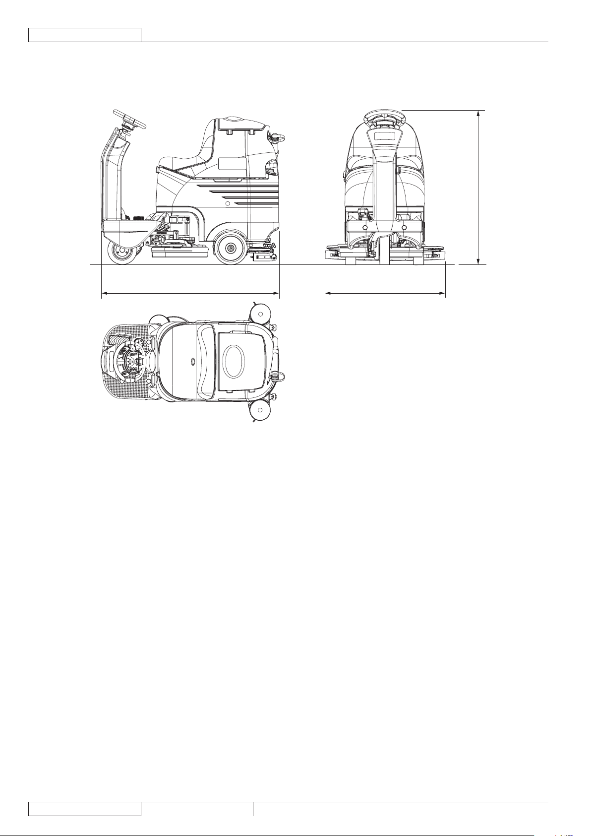
1190 mm (46.85 in)
890 mm (35 in)1360 mm (53.5 in)
DIMENSIONS
SC3000 26” Disc
P100367
Page 11
GENERAL INFORMATION
SERVICE MANUAL
ENGLISH
SC3000 26” Disc 9099052000
9
MAINTENANCE
The lifespan of the machine and its maximum operating safety are ensured by correct and regular maintenance.
WARNING!
Read carefully the instructions in the Safety chapter before performing any maintenance procedure.
The following tables provides the scheduled maintenance. The intervals shown may vary according to particular working conditions,
which are to be dened by the person in charge of the maintenance.
For instructions on maintenance procedures, see the following paragraphs.
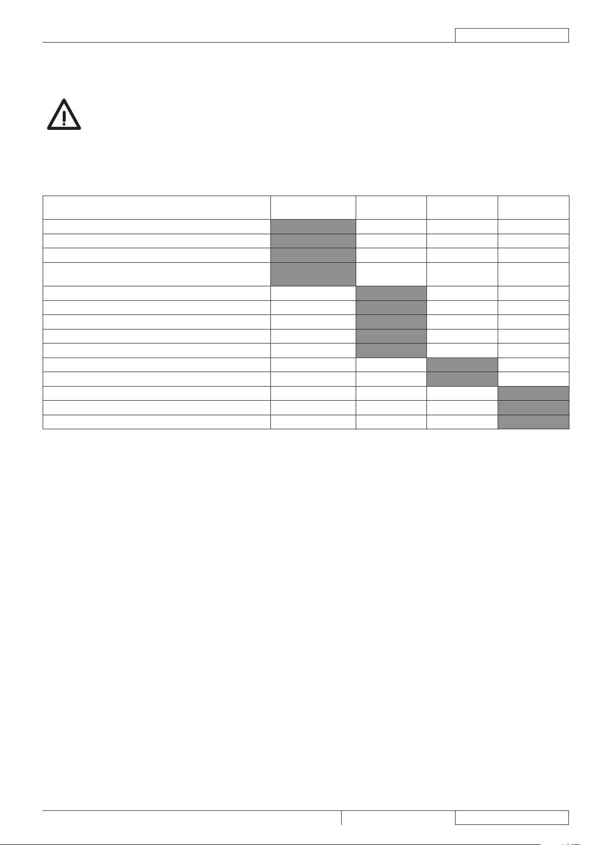
SCHEDULED MAINTENANCE TABLE
Procedure
Battery charging
Squeegee cleaning
Brush cleaning
Tank, debris collection grid and vacuum grid with oat
cleaning, and cover gasket check
EcoFlex™ system cleaning and draining (optional)
Squeegee blade check and replacement
Solution lter cleaning
Vacuum system motor lter cleaning
Battery (WET) uid level check
Screw and nut tightening check (1)
Electromagnetic brake efciency check
Brush/pad-holder motor carbon brush check or replacement
Vacuum system motor carbon brush check or replacement
Drive system motor carbon brush check or replacement
Daily, after using the
machine
Weekly
Every six
months
Yearly
And after the rst 8 working hours.(1)
Page 12
GENERAL INFORMATION
ENGLISH
SERVICE MANUAL
10
9099052000 SC3000 26” Disc
18 13 12 10 11 546
7
17 98
15
14
19
16
20
3
2
1
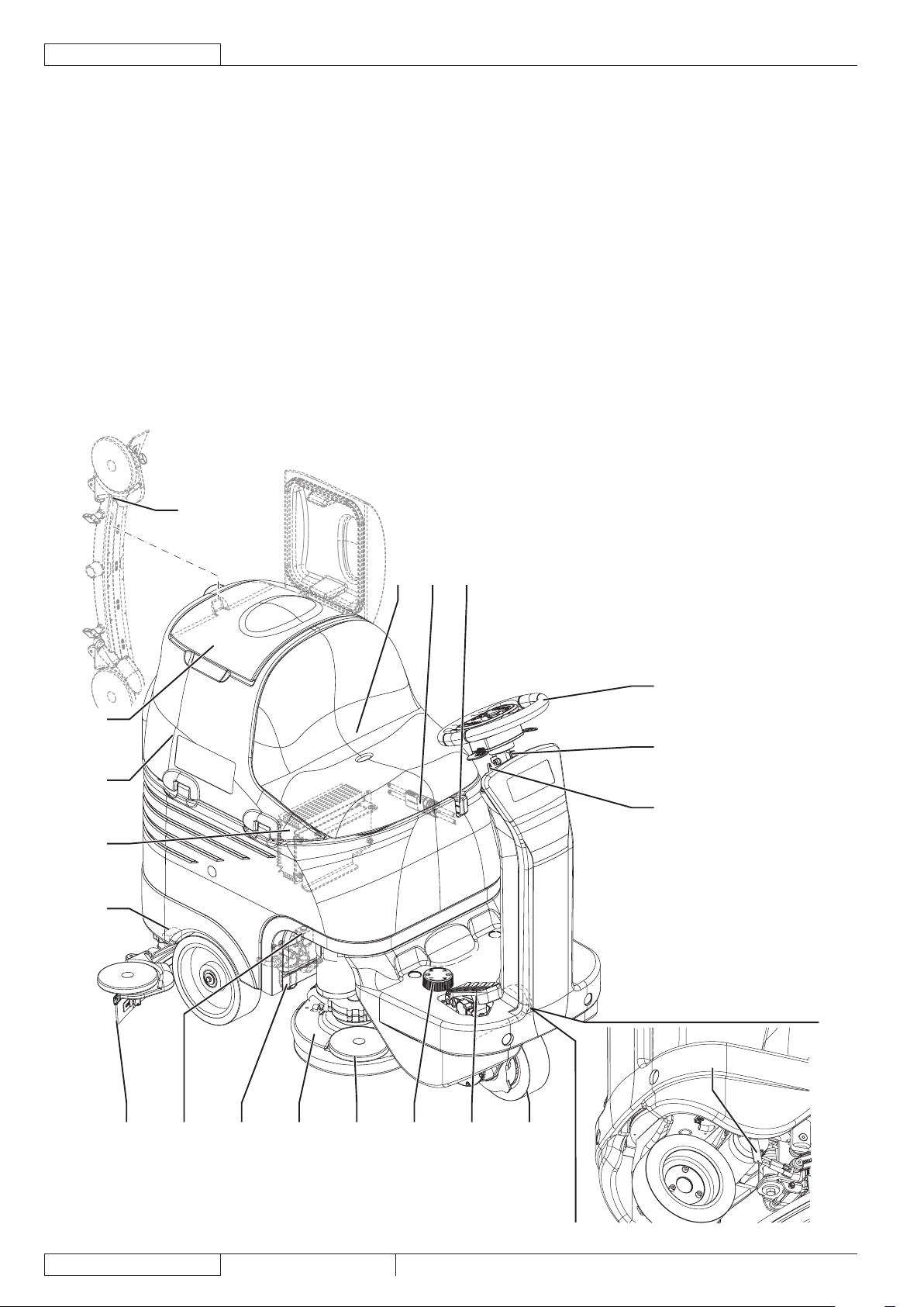
MACHINE NOMENCLATURE
Throughout this Manual you will nd numbers in brackets – for example: (2). These numbers refer to the components indicated in
these two nomenclature pages. Refer to these pages whenever you need to identify a component mentioned in the text.
Steering wheel with control panel (see the following 1.
paragraph)
Steering wheel height control lever2.
Ignition key3.
Drive pedal4.
Heel support height adjustment5.
Front steering, driving and braking wheel6.
Electromagnetic brake unlocking lever7.
Emergency push-button8.
Battery connector9.
Brush/pad-holder deck10.
Bumper wheel11.
Solution lter12.
Solenoid valve13.
Solution/clean water tank opening/closing valve14.
Squeegee hook15.
Battery charger (optional)16.
Seat17.
Squeegee blades assembly18.
(Dumping) recovery tank assembly19.
Recovery tank cover20.
P100370
Page 13
GENERAL INFORMATION
SERVICE MANUAL
ENGLISH
SC3000 26” Disc 9099052000
11
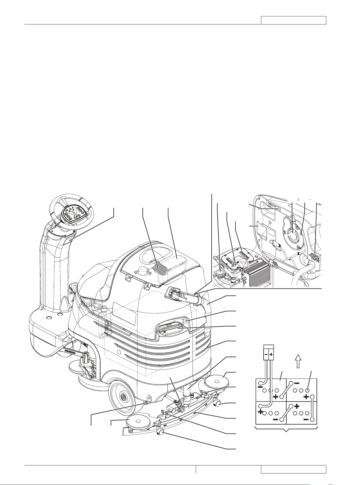
MACHINE NOMENCLATURE (Continues)
Front
24V
21 27 26
25
42
41
43
44
37 36
38
35
33
34
30
33
34
32
31
22
23
28
24
32
29
38
4039
Serial number plate/technical data/conformity certication21.
Solution/clean water tank22.
Solution/clean water tank ller plug with removable ller 23.
hose
Recovery water drain hose24.
Tank assembly stand25.
Container with debris collection grid26.
Vacuum grid with automatic shut-off oat27.
Solution/clean water draining adapter28.
Solution/clean water tap29.
Squeegee30.
Squeegee vacuum hose31.
Squeegee bumper wheels32.
Squeegee support wheels33.
Squeegee mounting handwheels34.
Squeegee balance adjusting handwheel35.
Vacuum system motor36.
Vacuum system motor lter37.
Battery connection diagram38.
Batteries39.
Battery caps40.
Battery charger cable (optional)41.
Detergent tank (*)42.
Electronic component compartment cover43.
(Lifted) recovery tank assembly and driver’s seat44.
Only for machine with EcoFlex™ system (optional)(*)
P100371
Page 14
GENERAL INFORMATION
ENGLISH
SERVICE MANUAL
12
9099052000 SC3000 26” Disc
52
54
53
56
55
51
57
58
59
60
72
70
71
68
67
65
69
66
63
64
62
61
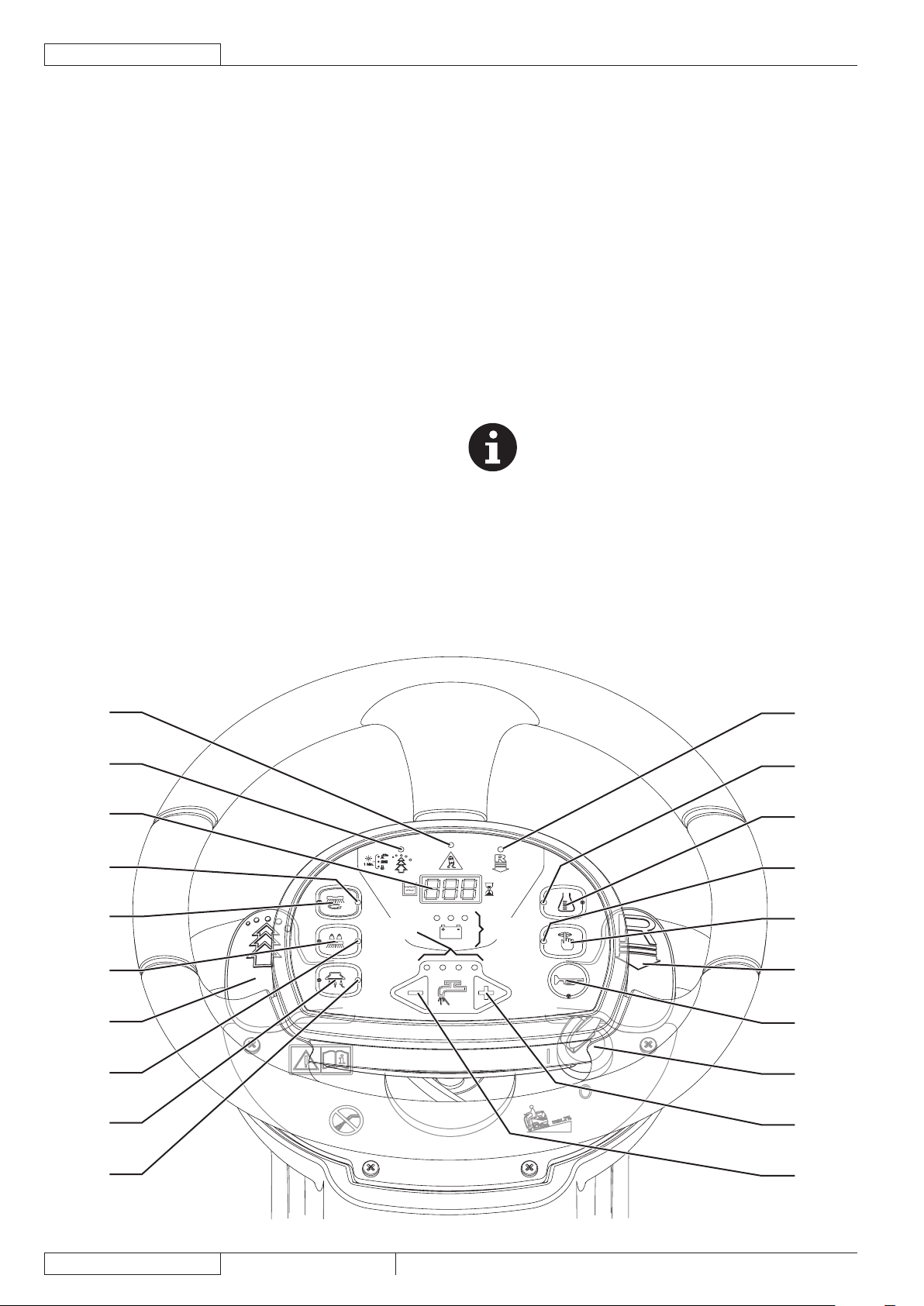
MACHINE NOMENCLATURE (Continues)
Reverse gear activation/deactivation lever51.
Reverse gear LED indicator52.
Detergent ow control switch (*)53.
Washing detergent ow control switch led indicator (*)54.
Mute function switch55.
Mute function switch LED56.
Horn switch57.
Ignition key58.
Solution ow increase switch59.
Solution ow decrease switch60.
Solution ow indicator61.
Battery warning lights62.
Green warning light - charged battery•
Yellow warning light - semi-discharged battery•
Red warning light - discharged battery•
Vacuum system switch63.
Vacuum system led indicator64.
Extra pressure switch65.
Extra pressure led indicator66.
Brush/pad-holder deck and squeegee lifting/lowering 67.
switch
Brush/pad-holder deck and squeegee lifting/lowering LED 68.
indicator
EcoFlex™ activation/deactivation lever (*)69.
EcoFlex™ system LED indicator (*):70.
LED on - EcoFlex™ system on•
LED ashing - EcoFlex™ system override•
Hour counter and solution level display:71.
When the machine is started, it displays for a few •
seconds the number of working hours which have been
performed.
While using the machine, it displays the solution/ •
washing water level in the tank (in gallons).
When the level is above 18 USgal, the display indicates •
“FUL”.
When the level is under 4 USgal, the display indicates •
“LO”.
When the tank is almost empty, “LO” starts ashing.•
NOTE
The display could indicate “LO” even if the tank is
not completely empty, thus allowing to complete
the cleaning cycle; in any case, it is recommended
to check the actual solution ow supplied to the
brushes.
Anti-skid control activation LED indicator72.
Only for machine with EcoFlex™ system (optional)(*)
P100372
Page 15
SOLUTION/CLEAN WATER SUPPLY SYSTEM
SERVICE MANUAL
ENGLISH
SC3000 26” Disc 9099052000
13
A
A
B
D
E
F
G
G
C
H
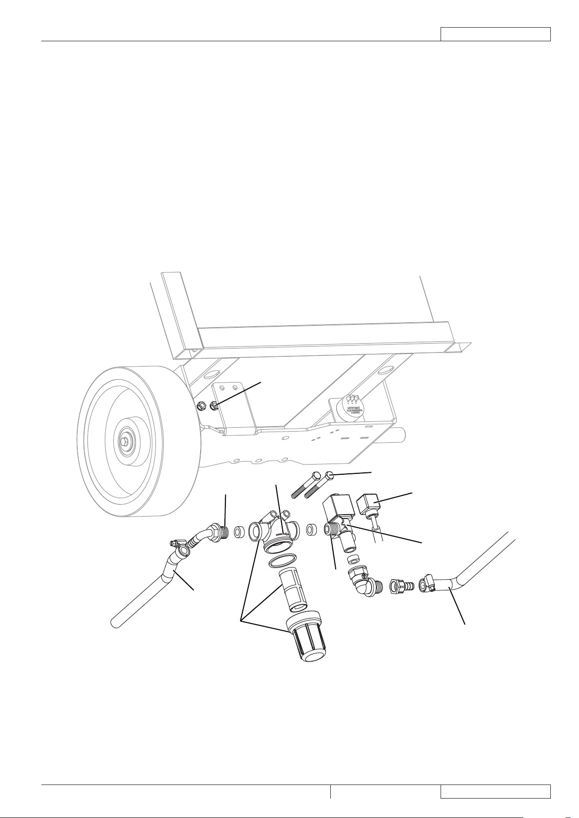
SOLUTION/CLEAN WATER SUPPLY SYSTEM
SOLENOID VALVE/SOLUTION SYSTEM FILTER DISASSEMBLY/ASSEMBLY
Disassembly
Place the machine on a hoisting system (if available), then lift it. Otherwise, drive the machine on a level oor.1.
Lower the brush deck.2.
Lower and remove the squeegee from the holder.3.
Turn the ignition key to “0” and disconnect the batteries.4.
On the right side of the machine, remove the screws and nuts (A).5.
Disconnect the connector (B).6.
Disconnect the hose (C) and (D).7.
Recover the whole assembly and, at the workbench, remove the solenoid valve (E), or the lter assembly (F) by disconnecting/8.
unscrewing the connecting/fastening components.
Assembly
Assemble the components in the reverse order of disassembly, and note the following:9.
Before screwing the threaded ttings (G) clean them, then apply Teon tape, according to the screwing direction.•
When assembling the lter (F) the stamped arrow (H) must be tuned in the direction of the solution ow.•
P100373
Page 16
SOLUTION/CLEAN WATER SUPPLY SYSTEM
ENGLISH
SERVICE MANUAL
14
9099052000 SC3000 26” Disc
TROUBLESHOOTING
Small amount of solution or no solution reaches the brush
Possible causes:
The tank lter (optional) is clogged/dirty (clean).1.
The solution lter is clogged/dirty (clean).
The solution tap is closed/semi-closed (replace).2.
The solenoid valve (EV1) is broken or there is an open in the electrical connection (replace the solenoid valve/repair the 3.
electrical connection).
There is debris in the solution/clean water tank clogging the output hole (clean the tank).4.
There is debris in the solution/clean water hoses clogging the ow (clean the hoses).5.
The function electronic board (EB1) is faulty (replace).6.
The display electronic board (EB2) is faulty (replace).7.
The dashboard electronic board (EB3) is faulty (replace).8.
The solution reaches the brush also when the machine is off
Possible causes:
There is dirt or calcium deposit on the solenoid valve gasket (clean).1.
The solenoid valve is broken (replace).2.
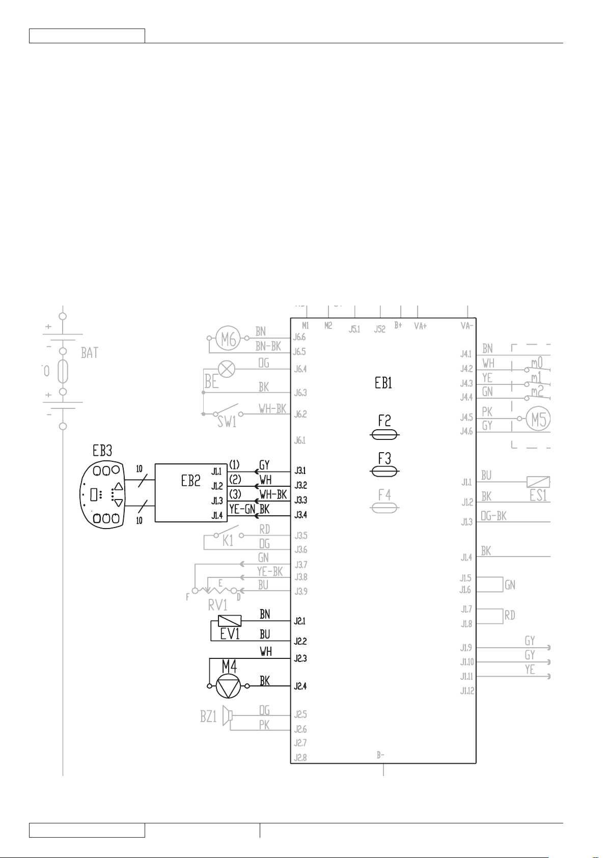
WIRING DIAGRAM
P100374A
Page 17
ECOFLEX™ SYSTEM
SERVICE MANUAL
ENGLISH
SC3000 26” Disc 9099052000
15
A
E
G
ECOFLEX™ SYSTEM
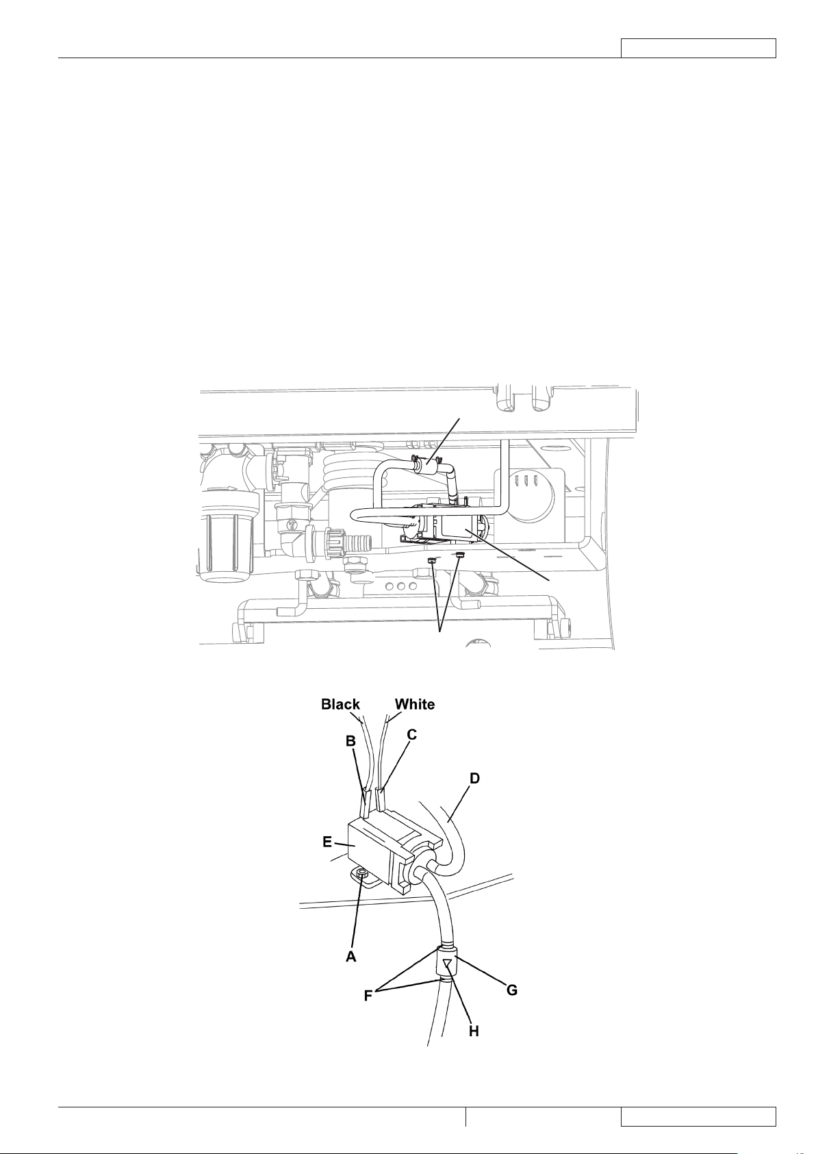
DETERGENT PUMP AND ONE-WAY VALVE DISASSEMBLY/ASSEMBLY
Disassembly
Place the machine on a hoisting system (if available), then lift it. Otherwise, drive the machine on a level oor.1.
Lower the brush deck.2.
Turn the ignition key to “0” and disconnect the batteries.3.
Open the detergent tank plug (42).4.
On the left side of the machine, remove the screws and nuts (A).5.
Disconnect the connectors (B) and (C).6.
Disconnect the hose (D).7.
Remove the detergent pump (E).8.
If necessary, remove the retaining springs (F) and disconnect the one-way valve (G) from the relevant hoses.9.
Assembly
Assemble the components in the reverse order of disassembly, and note the following:10.
Connect the connector with black cable (B) and white cable (C) as shown in the gure.•
Install the one-way valve (G) with the arrow (H) turned in the direction of the detergent ow.•
P100375
P100376
Page 18
ECOFLEX™ SYSTEM
ENGLISH
SERVICE MANUAL
16
9099052000 SC3000 26” Disc
C
B
A
ECOFLEX™ SYSTEM DISABLING PROCEDURE
In order to permanently disable the EcoFlex™ system, proceed as follows:
Turn off the machine by turning the ignition key (58) to “0”.1.
Lift the lever (69), then turn the ignition key (58) to “I”.2.
Release the lever (69) at least 8 seconds after turning on the machine.3.
After this procedure, the EcoFlex™ the lever cannot be operated again (LED (70) off) and the detergent concentration level is the
one which has been set.
In order to re-enable the system, repeat the steps 1 to 3.
NOTE
The permanent disabling of the EcoFlex™ system is stored into memory even after the machine is turned off.
TROUBLESHOOTING
Small amount of detergent or no detergent reaches the brush
Possible causes:
The detergent ow percentage is too low (check/change the percentage as shown in the Operator manual).1.
The hydraulic circuit upstream of the detergent pump is not triggered (check if the hose is lled and, if necessary, perform one 2.
or more draining cycle, as shown in the relevant paragraph of the Operator manual).
The pump (M1) is broken or there is an open in the electrical connection (replace the pump/repair the electrical connection).3.
There is foreign material/debris in the detergent tank clogging the output hole (clean the tank).4.
There is debris in the detergent hoses clogging the detergent ow (clean the hoses).5.
The detergent ow control switch is malfunctioning (check that the LED (78) turns on; if necessary, replace the dashboard 6.
electronic board).
The function electronic board (EB1) is not set for the operation with EcoFlex™ system (if equipped, remove the jumper wire 7.
(J4) in front of the electronic board).
The function electronic board (EB1) is faulty (replace).8.
The display electronic board (EB2) is faulty (replace).9.
The dashboard electronic board (EB3) is faulty (replace).10.
The detergent reaches the brush also when the machine is off
Possible causes:
The pump (M1) is broken (replace).1.
The one-way valve is broken (replace).2.
There is water in the detergent tank
Possible causes:
The one-way valve is broken (replace).1.
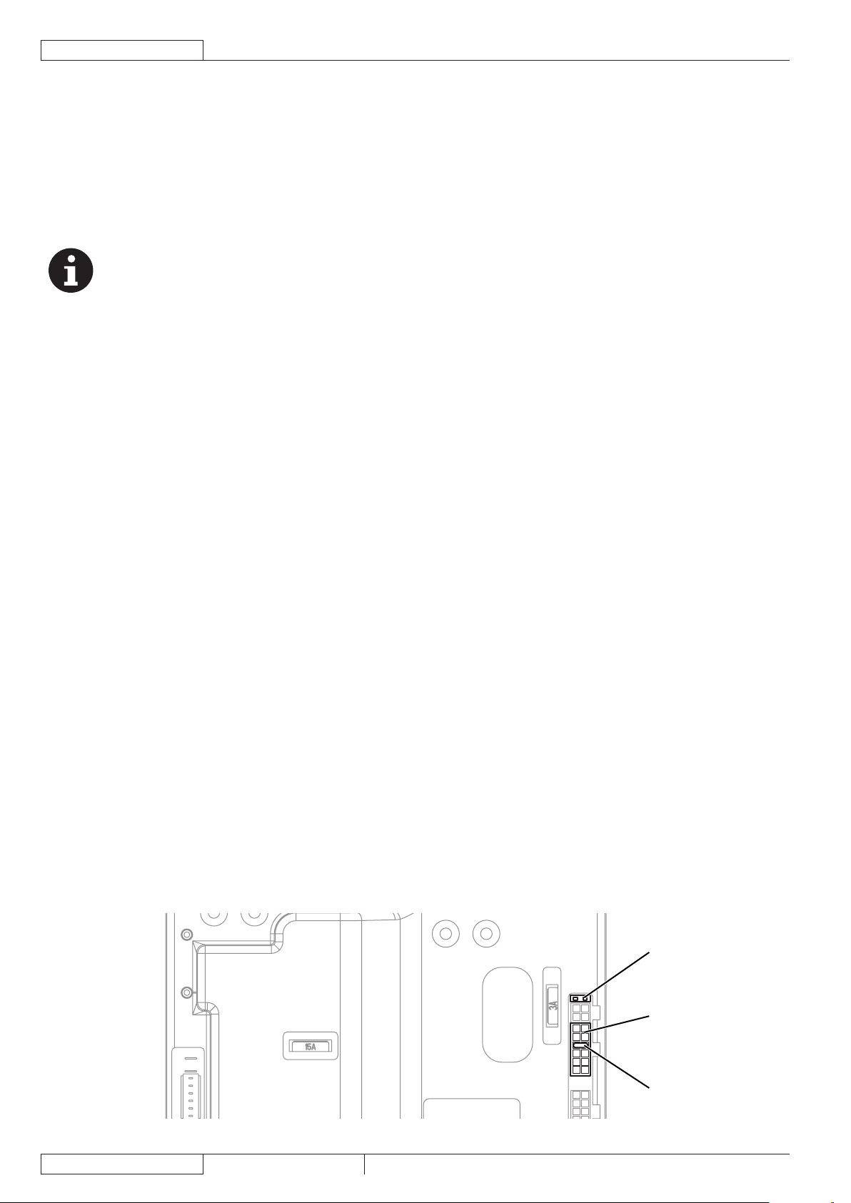
The EcoFlex™ system does not work in the “US mode” but in the “EU mode”.
Possible causes:
Check the GREEN bridge from pin 5 to pin 6 (A) of the connector J1 (B): it has not to be present (if present, switch off the 1.
machine and cut it).
The EcoFlex™ system does not turn on when pressing the switch (77) and the LED (78) does not turn on
To check the function electronic board, remove the panel as shown in Function Electronic Board Disassembly/Assembly paragraph
(steps 1 to 4).
Possible causes:
The function electronic board (EB1) is not set for the operation with EcoFlex™ system [if present, remove the jumper wire J8 1.
(C) behind of the electronic board].
The dashboard electronic board (EB3) is faulty (replace).2.
P100377A
Page 19
BRUSHING SYSTEM
SERVICE MANUAL
ENGLISH
SC3000 26” Disc 9099052000
17
BRUSHING SYSTEM
B
D
A
C
F
E
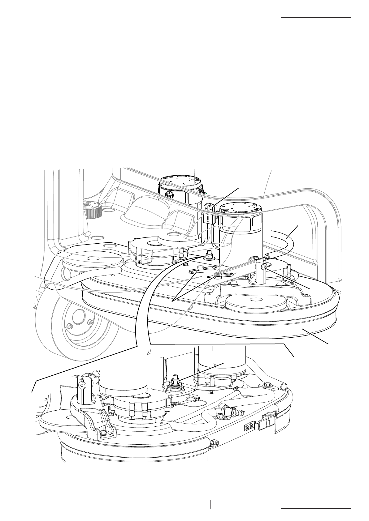
BRUSH/PAD-HOLDER DECK DISASSEMBLY/ASSEMBLY
Disassembly
Drive the machine on a level oor or on a lift platform to facilitate disassembly.1.
Remove the brushes, as shown in the Operator manual.2.
Turn the ignition key (58) on “I”.3.
Pressing the switch (67) to lower the brush/pad deck.4.
Turn the ignition key (58) to “0”.5.
Disconnect the red connector (A).6.
Unplug the pipe (B) of the cleaning solution.7.
Unscrew the screw (C) and recover the nut.8.
Remove the safety pins (D).9.
Unscrew the nut (E) and recover the washer, then remove the brush/pad-holder deck (F).10.
Assembly
Assemble the components in reverse order of disassembly.11.
Page 20
BRUSHING SYSTEM
ENGLISH
SERVICE MANUAL
18
9099052000 SC3000 26” Disc
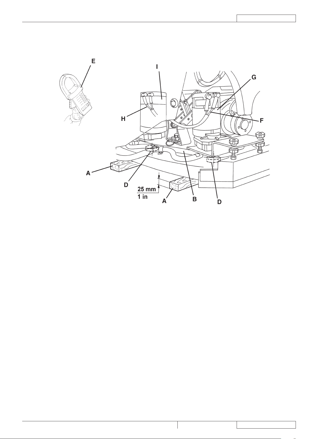
BRUSH MOTOR ELECTRICAL INPUT CHECK
WARNING!
This procedure must be performed by qualied personnel only.
Drive the machine on a level oor.1.
Remove the brushes, as shown in the Operator manual.2.
Place two wooden shims (A) under the brush deck sides (B), as shown in the gure. Wooden shim thickness must be 1 in (25 3.
mm).
WARNING!
Keep the wooden shims at an appropriate distance from the brush hubs.
Use a jumper wire to disable the driver’s seat microswitch.4.
Disconnect the driving wheel connector to disable the drive system.5.
Turn the ignition key (58) to “I”.6.
Lower the brush/pad-holder deck by pressing the switch (67).7.
Apply the amperometric pliers (E) on one cable (F) of the right motor (G), or on one cable (H) of the left motor (I).8.
Turn on the brushes by pressing the drive pedal (4), then check that the electrical input of the right (G) or left motor (I) is as 9.
follows:
3 to 4 A at 24V, for the brush/pad-holder deck motors;•
Turn off the brushes by releasing the drive pedal (4) and lift the brush/pad-holder deck by pressing the switch (67).10.
Turn the ignition key (58) to “0”.11.
Remove the amperometric pliers (A).
If the electrical input is higher, perform the following procedures to detect and correct the abnormal input:
NOTE
If the electrical input is higher than the maximum allowed value, the 3 battery warning lights (81) ash simultaneously.
Check the tightening of F1 fuse screw (see the procedure in Fuse check/replacement paragraph).•
Check if there is dust or dirt (ropes, cables, etc.) on the brush hubs.•
Check the motor carbon brushes (see the procedure in the relevant paragraph).•
Remove the motors (see the procedure in the relevant paragraph), and check the condition of all components.•
If the above-mentioned procedures do not lead to a correct electrical input, the motors must be replaced (see the procedure in
the relevant paragraph).
Reset
Connect the driving wheel connector.12.
Remove the jumper wire and enable the driver’s seat microswitch.13.
Remove the wooden shims and install the brushes.14.
Page 21
BRUSHING SYSTEM
SERVICE MANUAL
ENGLISH
SC3000 26” Disc 9099052000
19
BRUSH MOTOR ELECTRICAL INPUT CHECK (Continues)
S301326
Page 22

BRUSHING SYSTEM
ENGLISH
SERVICE MANUAL
20
9099052000 SC3000 26” Disc
BRUSH MOTOR CARBON BRUSH CHECK/REPLACEMENT
Check
Remove the brush/pad-holder deck.1.
Remove dust and dirt from the motor carbon brush support area (A).2.
Disengage the fasteners (B) and (C), then remove the four carbon brush supports (A). If necessary, disconnect the electrical 3.
connections (D).
Check the carbon brushes (E) for wear. Replace the carbon brushes when: the contact with the motor armature is insufcient, 4.
the carbon brushes are worn, the carbon brush contact surface is not integral, the thrust spring is broken, etc.
If necessary, disconnect the connections (F) and remove the carbon brushes with their supports (A) and replace them.5.
Replace the carbon brushes as an assembly.
Reset
Assemble the components in the reverse order of disassembly, and note the following:6.
When connecting the terminals (F), take care of their insulation from the surrounding parts of the frame.•
S301327A
Page 23

BRUSHING SYSTEM
SERVICE MANUAL
ENGLISH
SC3000 26” Disc 9099052000
21
BRUSH MOTOR DISASSEMBLY/ASSEMBLY
D
E
C
B
A
D
E
C
B
A
Disassembly
Remove the brush/pad-holder deck (see the procedure in the relevant paragraph).1.
At the workbench, remove the screw (A) from the reduction unit which has to be disassembled.2.
Remove the hub assembly (B) with a puller.3.
Remove the screws (C).4.
Remove the reduction unit (D).5.
Recover the key (E).6.
Assembly
Assemble the components in the reverse order of disassembly.7.
NOTE
For further information on deck components see the Spare Parts List.
P100378
Page 24

BRUSHING SYSTEM
ENGLISH
SERVICE MANUAL
22
9099052000 SC3000 26” Disc
A
B
C
BRUSH DECK LIFTING/LOWERING ACTUATOR DISASSEMBLY/ASSEMBLY
Disassembly
Lower the brush deck.1.
Remove the brush deck (see the procedure in the relevant paragraph).2.
Turn the ignition key to “0” and disconnect the batteries.3.
Disconnect the actuator connector (see the function electronic board).4.
Remove the screw (A) and recover nuts, bushings and washers.5.
Remove the screw (B) and recover the washer.6.
Remove the actuator (C).7.
Assembly
Assemble the components in the reverse order of disassembly.8.
P100381
Page 25

BRUSHING SYSTEM
SERVICE MANUAL
ENGLISH
SC3000 26” Disc 9099052000
23
BRUSH DECK ADJUSTER SPRING DISASSEMBLY/ASSEMBLY
A
B
C
D
Disassembly
Drive the machine on a level oor.1.
Remove the brush/pad-holder deck (see the procedure in the relevant paragraph).2.
Turn the ignition key to “0” and disconnect the batteries.3.
Remove the front fairing (see the procedure in the relevant paragraph).4.
Place a wooden shim (A) under the deck holder assembly. Wooden shim thickness must be 160 mm.5.
Unscrew the ring nut (B), recover the washer, then carefully remove the spring (C).6.
If necessary, replace the spring taking care to properly place the elastic ends (D) on the frame.7.
Assembly
Assemble the components in the reverse order of disassembly, and note the following:8.
Tighten the ring nut (B) so that the deck holder assembly can turn freely.•
P100382
Page 26

BRUSHING SYSTEM
ENGLISH
SERVICE MANUAL
24
9099052000 SC3000 26” Disc
A
B
BRUSH DECK DRIVE GUIDE DISASSEMBLY/ASSEMBLY
Disassembly
Drive the machine on a level oor.1.
Remove the brush/pad-holder deck (see the procedure in the relevant paragraph) and leave the deck holder assembly lifted.2.
Turn the ignition key to “0” and disconnect the batteries.3.
Turn the steering wheel to accommodate the position of the drive guide (A) to be removed.4.
Under the machine, remove the screws (B) and the drive guide (A).5.
Replace the drive guide if it is too worn.6.
Assembly
Assemble the components in the reverse order of disassembly.7.
P100383
Page 27

BRUSHING SYSTEM
SERVICE MANUAL
ENGLISH
SC3000 26” Disc 9099052000
25
TROUBLESHOOTING
Open circuit
The fuse (F1) determines an open in the supply circuit of the brush deck motors. This system allows to prevent the circuits from
being damaged under overload conditions.
The open in the fuse can be caused by the following:
Short circuit in the brush motor wiring harness; fault in the motor.1.
All brushes do not turn
Possible causes:
The brush motor electromagnetic switch wiring harness is damaged (repair).1.
The function electronic board (EB1) is faulty (replace).2.
The wiring harness between function electronic board (EB1) and brush motor electromagnetic switch (ES1) is damaged 3.
(repair).
The brush motor electromagnetic switch (ES1) is damaged (replace).4.
The brush motor fuse (F1) is open (replace).5.
One brush does not rotate
Possible causes:
The motor carbon brushes are worn (replace).1.
Bulky debris or cords around the brushes or between the brushes and its ange (remove and clean the brushes).2.
The motor is faulty (repair or replace).3.
The wiring harness is damaged (repair).4.
The brushes cannot be lifted/lowered or the extra pressure function cannot be turned on
Possible causes:
See the Electrical System chapter, function electronic board error codes.1.
The deck lifting/lowering actuator (M5) end-of-stroke microswitches are broken (replace the actuator).2.
The deck lifting/lowering actuator (M5) is broken (replace).3.
There is an open in the actuator wiring harness (check the connections according to the procedures shown in the Electrical 4.
System chapter, Troubleshooting paragraph).
The actuator fuse (F4) is open (replace).5.
The function electronic board (EB1) is damaged (replace).6.
Page 28

BRUSHING SYSTEM
ENGLISH
SERVICE MANUAL
26
9099052000 SC3000 26” Disc
WIRING DIAGRAM
P100384A
Page 29

RECOVERY WATER SYSTEM
SERVICE MANUAL
ENGLISH
SC3000 26” Disc 9099052000
27
B
A
RECOVERY WATER SYSTEM
VACUUM SYSTEM MOTOR ELECTRICAL INPUT CHECK
WARNING!
This procedure must be performed by qualied personnel only.
Apply the amperometric pliers (A) on one cable (B) of the batteries.1.
Turn the ignition key (58) to “I”.2.
Turn on the vacuum system by pressing the switch (63) and check that the motor electrical input is 16 - 19 A at 24 V.3.
Turn off the vacuum system motor by pressing the switch (63).4.
Remove the amperometric pliers (B).
If the electrical input exceeds the specications, check the motor carbon brushes (see the procedure in the relevant
paragraph).
If necessary, remove the vacuum system motor (see the procedure in the relevant paragraph), and check the condition of its
moving parts.
If the above-mentioned procedures do not lead to a correct electrical input, the motor must be replaced (see the procedure in
the relevant paragraph).
Perform steps 3 and 4 in the reverse order.5.
S301553
Page 30

RECOVERY WATER SYSTEM
ENGLISH
SERVICE MANUAL
28
9099052000 SC3000 26” Disc
VACUUM SYSTEM MOTOR CARBON BRUSH CHECK/REPLACEMENT
Remove the vacuum system motor (see the procedure in the relevant paragraph).1.
At the workbench, remove the screws and the cover (A) from the vacuum system motor (B).2.
Remove the screws (C).3.
Disconnect the electrical connections (D).4.
Remove the carbon brushes (E).5.
Check the carbon brushes for wear. Replace the carbon brushes when: the contact with the motor armature is insufcient, the 6.
carbon brushes are worn, the carbon brush contact surface is not integral, the thrust spring is broken, etc.
If necessary, replace the carbon brushes. Replace the carbon brushes as an assembly.7.
Assemble the components in the reverse order of disassembly.8.
S301555
Page 31

RECOVERY WATER SYSTEM
SERVICE MANUAL
ENGLISH
SC3000 26” Disc 9099052000
29
VACUUM SYSTEM MOTOR DISASSEMBLY/ASSEMBLY
L
K
J
I
E
H
G
F
A
A
B
C
D
L
Disassembly
If there is recovery water in the tank, drain it.1.
Turn the ignition key to “0” and disconnect the batteries.2.
Lift the recovery tank.3.
Remove the screws (A) and recover the washers.4.
Remove the motor cover (B).5.
Remove the lter (C) and the gasket (D).6.
Remove the motor (E) or (L), the sound-deadening pipe (F) and the sound-deadening panel (G).7.
Disconnect the connector (H) of the motor (E).8.
Check the efciency of the gasket (I) and, if necessary, replace it.9.
Assembly
Assemble the components in the reverse order of disassembly.10.
S301556B
Page 32

RECOVERY WATER SYSTEM
ENGLISH
SERVICE MANUAL
30
9099052000 SC3000 26” Disc
AB
DC
E
F
G
SQUEEGEE LIFTING ACTUATOR DISASSEMBLY/ASSEMBLY
Disassembly
Lower the squeegee.1.
Turn the ignition key to “0” and disconnect the batteries.2.
Disengage the cable grommet (A) and remove it from the squeegee.3.
Remove the screws (B) and recover the washers.4.
Remove the screw (C) and recover the nut.5.
Disconnect the connector (D) and remove the squeegee lifting assembly (E).6.
At the workbench, remove the screw (F), recover the spacers and the nut.7.
Remove the squeegee lifting actuator (G).8.
Assembly
Assemble the components in the reverse order of disassembly.9.
P100385
Page 33

RECOVERY WATER SYSTEM
SERVICE MANUAL
ENGLISH
SC3000 26” Disc 9099052000
31
SQUEEGEE LIFTING CABLE DISASSEMBLY/ASSEMBLY
A
B
D
E
F
A
D
C
E
F
Front
Front
Disassembly
Remove the squeegee lifting assembly (see the previous paragraph, steps 1 to 6).1.
At the workbench, remove the screw (A) and recover the nut.2.
Carefully remove the squeegee lifting cable (B) from the pulleys.3.
Assembly
Install the lifting cable and note the following:4.
Grease the cable along its entire length with AGIP GR 30 or equivalent grease.•
Insert the cable in the direction shown by the arrow (C).•
Route the cable in the pulleys (D), (E) and (F) in sequence.•
Fasten the cable grommet with the screw (A) and nut.•
The components must be carefully installed as shown in the gure for the proper operation of the lifting system.5.
Install the squeegee lifting assembly (see the previous paragraph).6.
Check the proper operation of the squeegee lifting system.7.
NOTE
The squeegee lifting system pulleys are self-lubricating and do not require maintenance.
P100386
Page 34

RECOVERY WATER SYSTEM
ENGLISH
SERVICE MANUAL
32
9099052000 SC3000 26” Disc
TROUBLESHOOTING
The vacuum system motor does not turn on
Possible causes:
The wiring harness between function electronic board and vacuum system motor is damaged (repair).1.
The vacuum system motor carbon brushes are worn (replace).2.
The vacuum system motor is faulty (check the electrical input).3.
The function electronic board (ES1) is damaged (replace).4.
Dirty water vacuuming is insufcient or there is no vacuuming
Possible causes:
The vacuum grid with automatic shut-off oat is activated because the recovery tank is full (empty the recovery tank).1.
The debris tray is clogged (clean).2.
The vacuum grid with automatic shut-off oat is dirty, or the vacuum pre-lter is dirty (clean).3.
The tank cover is not correctly positioned (adjust).4.
The tank cover gasket is not efcient, or the compensating hole is clogged (repair/clean).5.
The vacuum system motor lter is dirty (clean).6.
The squeegee or the vacuum hose is clogged or damaged (clean or repair/replace).7.
The vacuum gaskets are damaged or do not match perfectly (repair or replace).8.
The squeegee leaves lining on the oor or does not collect water
Possible causes:
There is debris under the blade (remove).1.
The squeegee blade edges are torn or worn (replace).2.
The squeegee is not balanced (adjust it with the relevant handwheel).3.
The squeegee does not lift/lower
Possible causes:
See the Electrical System chapter, function electronic board diagnosis.1.
The cable is broken (replace).2.
The actuator (M6) is faulty (replace).3.
The actuator fuse (F4) is open (replace).4.
Page 35

RECOVERY WATER SYSTEM
SERVICE MANUAL
ENGLISH
SC3000 26” Disc 9099052000
33
WIRING DIAGRAM
P100387A
Page 36

RECOVERY WATER SYSTEM
ENGLISH
SERVICE MANUAL
34
9099052000 SC3000 26” Disc
Page 37

PARKING BRAKE SYSTEM
SERVICE MANUAL
ENGLISH
SC3000 26” Disc 9099052000
35
PARKING BRAKE SYSTEM
A
D
C
B
ELECTROMAGNETIC BRAKE DISASSEMBLY/ASSEMBLY
Disassembly
Place the machine on a hoisting system (if available), then lift it. Otherwise, drive the machine on a level oor.1.
Lower the brush deck.2.
Turn the ignition key to “0” and disconnect the batteries.3.
Turn the steering wheel to reach the electromagnetic brake.4.
On the left side of the machine, remove the screws (A) and disconnect the connector (B).5.
Remove the electromagnetic brake (C).6.
Assembly
Assemble the components in the reverse order of disassembly, and note the following:7.
Before installing the electromagnetic brake (C) clean it with compressed air.•
Install the electromagnetic brake with the lever (D) downwards.•
After installing the electromagnetic brake check the parking brake.8.
P100388
Page 38

PARKING BRAKE SYSTEM
ENGLISH
SERVICE MANUAL
36
9099052000 SC3000 26” Disc
TROUBLESHOOTING
The brake does not operate
Possible causes:
The electromagnetic brake deactivation lever is turned to unlock position (remove the shim).1.
The braking masses are not efcient (replace the electromagnetic brake).2.
The brake does not activate when pressing the forward/reverse gear pedal
Possible causes:
There is an open in wiring harness between function electronic board and electromagnetic brake (check/repair the wiring 1.
harness/electrical connections).
The electromagnetic brake (BRK) is faulty (replace).2.
The function electronic board (ES1) is faulty (replace).3.
Page 39

PARKING BRAKE SYSTEM
SERVICE MANUAL
ENGLISH
SC3000 26” Disc 9099052000
37
WIRING DIAGRAM
P100389A
Page 40

PARKING BRAKE SYSTEM
ENGLISH
SERVICE MANUAL
38
9099052000 SC3000 26” Disc
Page 41

DRIVE SYSTEM
SERVICE MANUAL
ENGLISH
SC3000 26” Disc 9099052000
39
DRIVE SYSTEM
DRIVE SYSTEM MOTOR ELECTRICAL INPUT CHECK
WARNING!
This procedure must be performed by qualied personnel only and with the help of an assistant.
Drive the machine on a level oor.1.
Apply proper wedges to rear wheels, so that the machine cannot move when the front wheel is lifted.2.
Slightly lift the front part of the machine and apply to the frame brackets two proper wooden shims high enough to keep the 3.
front wheel lifted for about 3/4” (2 cm) from the oor.
WARNING!
Pay attention to the rotation of the driving wheel when performing the following steps.
Use a jumper wire to disable the driver’s seat microswitch.4.
Apply the amperometric pliers on the positive cable (red) of the battery wiring harness.5.
Turn the ignition key (58) to “I”.6.
Drive the machine at the maximum forward speed by pressing the pedal (4) and check that the electrical input is 5 - 7 A at 24 7.
V. Release the pedal (4). Turn the ignition key (58) to “0” and remove the amperometric pliers.
If the electrical input is higher, perform the following procedures to detect and correct the abnormal input:
Check if there is dust or debris preventing the wheel rotation.•
If necessary, check if the electromagnetic brake slows down the wheel when the drive system motor is operating (remove •
the electromagnetic brake and repeat the electrical input check (see the procedure in the relevant paragraph)).
If necessary, check the motor carbon brushes (see the procedure in the relevant paragraph).•
If necessary, disassemble the motor (see the procedure in the relevant paragraph), and check the condition of all its •
components.
If the above-mentioned procedures do not lead to a correct electrical input, the motor must be replaced (see the procedure in
the relevant paragraph).
Page 42

DRIVE SYSTEM
ENGLISH
SERVICE MANUAL
40
9099052000 SC3000 26” Disc
D
EF
CA
BB
F
G
DRIVE SYSTEM MOTOR CARBON BRUSH CHECK/REPLACEMENT
Check and replacement
Drive the machine on a level oor.1.
Turn the ignition key to “0” and disconnect the batteries.2.
Remove the electromagnetic brake (see the procedure in the relevant paragraph).3.
Remove the drive system motor (see the procedure in the relevant paragraph).4.
At the workbench, with indelible pen mark the installation position of the ange on the drive system motor (A).5.
Remove the screws (B), the ange (C) and the plastic ring (D).6.
Disengage the thrust spring (E) and remove the 2 carbon brushes (F).7.
Check the carbon brushes for wear.8.
The carbon brushes are worn when the contact with the motor armature is insufcient, the contact surface is not even, the
thrust spring is broken, etc.
If necessary, replace the carbon brushes.
Reset
Assemble the components in the reverse order of disassembly, and note the following:9.
Clean (with compressed air) the area around the carbon brushes and the removed components.•
Assemble the carbon brushes (F) with the cables (G) positioned as shown in the gure.•
Install the ange (C) on the drive system motor using the mark (A) as reference.•
P100390
Page 43

DRIVE SYSTEM
SERVICE MANUAL
ENGLISH
SC3000 26” Disc 9099052000
41
DRIVE SYSTEM MOTOR DISASSEMBLY/ASSEMBLY
Disassembly
Drive the machine on a level oor.1.
Turn the ignition key to “0” and disconnect the batteries.2.
Under the driving wheel assembly, disconnect the drive system motor and electromagnetic brake connections (A).3.
Remove the electromagnetic brake (see the procedure in the relevant paragraph).4.
Remove the driving wheel assembly (see the procedure in the relevant paragraph).5.
At the workbench, with indelible pen mark the installation position of the motor on the gear box (B).6.
Remove the screws (C) and carefully remove the drive system motor (D).7.
Check the oil seal gasket (E) for wear. In case of oil leaks between the drive system motor and the gear box, replace the oil 8.
seal as indicated below.
Oil seal replacement
Remove the screw (F) and recover the washer.9.
Carefully remove the gear (G) from the motor pin (I).10.
Remove and replace the oil seal gasket (H).11.
Rub the pin (I) of the drive system motor with 400 grit sand paper. Clean the pin with thinner.12.
Apply 13. Loctite 542 on the pin (I) and on the gear (G), then install.
Apply strong threadlock on the threads of the screw (F), then tighten the screw at 7,4 ftlbs (10 Nm).14.
Assembly
Assemble the components in the reverse order of disassembly, and note the following:15.
Check the oil level in the hole (J) of the gear box. If necessary, top up with SAE 80W/90 oil.•
Install the drive system motor on the gear box motor using the mark (B) as reference.•
Page 44

DRIVE SYSTEM
ENGLISH
SERVICE MANUAL
42
9099052000 SC3000 26” Disc
A B
C
D E
J
F
G
H
I
DRIVE SYSTEM MOTOR DISASSEMBLY/ASSEMBLY (Continues)
P100391
Page 45

DRIVE SYSTEM
SERVICE MANUAL
ENGLISH
SC3000 26” Disc 9099052000
43
DRIVING WHEEL DISASSEMBLY/ASSEMBLY
WARNING!
This procedure must be performed by qualied personnel only and with the help of an assistant.
Drive the machine on a level oor.1.
Turn the ignition key to “0” and disconnect the batteries.2.
Remove the machine foot board (see the procedure in the relevant paragraph).3.
Apply proper wedges to rear wheels, so that the machine cannot move when the front side is lifted.4.
Lift the front part of the machine and apply to the frame front sides two proper wooden shims high enough to keep the front 5.
wheel lifted for about 4 in (10 cm) from the oor.
Under the driving wheel assembly, disconnect the drive system motor and electromagnetic brake connections.6.
Remove the screws (A) and recover the washers.7.
Carefully lower the driving wheel assembly with steering, paying attention to the wiring harness (B).8.
Remove the screws (C), then remove the main gear (D) and the wiring harness shield (E). Note the wiring harness routing 9.
under the shield (E), for proper reassembly.
Remove the screws (F) and remove the driving wheel (G).10.
Remove the screws (H), recover the washers and remove the wheel (H).11.
Assembly
Assemble the components in the reverse order of disassembly, and note the following:12.
Tighten the screws (H) at 11,8 ftlbs (16 Nm).•
When installing the driving wheel assembly, the gears must be coupled with the straight wheel and the arrows (J) aligned •
as shown in the gure.
Tighten the screws (F, C and A) at 16,21 ftlbs (22 Nm).•
Page 46

DRIVE SYSTEM
ENGLISH
SERVICE MANUAL
44
9099052000 SC3000 26” Disc
A
F
F
G
C
E
D
B
I
J
H
DRIVING WHEEL DISASSEMBLY/ASSEMBLY (Continues)
P100392
Page 47

DRIVE SYSTEM
SERVICE MANUAL
ENGLISH
SC3000 26” Disc 9099052000
45
DRIVER’S SEAT SAFETY MICROSWITCH REPLACEMENT
Disassembly
Drive the machine on a level oor.1.
Turn the ignition key to “0” and disconnect the batteries.2.
Lift the recovery tank assembly (19) and remove the driver’s seat mounting screws.3.
Disconnect the microswitch connector.4.
Lift the recovery tank cover (20) and remove the remaining driver’s seat mounting screws.5.
Remove the driver’s seat, remove the wiring harness from the hole and then remove the driver’s seat microswitch by peeling 6.
off the adhesive.
Assembly
Assemble the components in the reverse order of disassembly.7.
Check that the machine cannot be stared when the operator is not on the driver’s seat (17).8.
TROUBLESHOOTING
The machine does not move
Possible causes:
The battery voltage is too low (charge the battery).1.
The drive pedal potentiometer (4) is misadjusted or broken (adjust or replace) (RV1).2.
The function electronic board (EB1) is faulty (replace).3.
The wiring harness is damaged (check all connections inside the electrical component compartment, included those of the 4.
function electronic board).
The drive system motor carbon brushes are worn (replace).5.
The drive system motor (M3) is faulty (replace).6.
The driver’s seat microswitch is faulty (repair/replace).7.
The parking brake cannot be disengaged (see the Parking Brake chapter).8.
There is an open in the function electronic board fuse (F2) (replace).9.
The function electronic board (EB1) is faulty (see the Electrical System chapter).10.
FUNCTION ELECTRONIC BOARD ERROR CODES
The function electronic board error codes indicate the drive system faults (see the Function Electronic Board Error Codes
paragraph).
Page 48

DRIVE SYSTEM
ENGLISH
SERVICE MANUAL
46
9099052000 SC3000 26” Disc
WIRING DIAGRAM
P100393A
Page 49

OTHER SYSTEMS
SERVICE MANUAL
ENGLISH
SC3000 26” Disc 9099052000
47
OTHER SYSTEMS
SCREW AND NUT TIGHTENING CHECK
Drive the machine on a level oor with the recovery tank empty.1.
Turn the ignition key to “0” and disconnect the batteries.2.
Carefully lift the tank assembly.3.
Then check:4.
Tightening of mounting screws and nuts•
Correct position of fasteners•
Visible faults in the components•
Leaks•
Carefully lower the tank assembly.5.
FRONT FAIRING DISASSEMBLY/ASSEMBLY
Disassembly
Drive the machine on a level oor with the recovery tank empty.1.
Turn the ignition key to “0” and disconnect the batteries.2.
Unscrew the steering wheel screw (A).3.
Remove the steering wheel assembly (B), disconnect the wiring harness connection.4.
Remove the cover (C), then remove the Seeger ring (D).5.
Remove the caps, the screws (E) and the steering wheel plate (F).6.
Disconnect the ignition switch wiring harness.7.
Remove the screws (G), recover the washers, disconnect the wiring harness and then remove the drive pedal (H).8.
Remove the adjustable heel support (I) and recover the spring (J).9.
Remove the caps, the screws (K) on the machine front and recover the washers.10.
Remove the caps, the screws (L) on the machine foot board and recover the washers and the nuts.11.
Carefully remove the front fairing (M).12.
Assembly
Assemble the components in the reverse order of disassembly.13.
Page 50

OTHER SYSTEMS
ENGLISH
SERVICE MANUAL
48
9099052000 SC3000 26” Disc
B
C
D
A
E
F
G
H
I
J
K
K
M
L
L
FRONT FAIRING DISASSEMBLY/ASSEMBLY (Continues)
P100394A
Page 51

ELECTRICAL SYSTEM
SERVICE MANUAL
ENGLISH
SC3000 26” Disc 9099052000
49
ELECTRICAL SYSTEM
MACHINE WORKING HOUR CHECK
Turn the ignition key (A) to “I”.1.
In the rst 2 seconds of machine operation, the display (B) shows the total number of working hours (ignition key to “I”) 2.
performed by the machine.
Turn the ignition key (A) to “0”.3.
It is possible to check the working hours performed by the machines through specic hour counters for: DRIVE SYSTEM,
BRUSHES, VACUUM SYSTEM (see Display of Current Values of Signicant Variables, Hour Counters and Stored Alarms
paragraph).
CHARGE CONDITION DISPLAY
INDICATION
1 GREEN LED: xed - YELLOW LED: xed 22 V 22.2 V -
2 YELLOW LED: xed - RED LED: ashing 20.4 V 21.6 V Brushes OFF
3 Safety threshold 19.4 V 20.6 V Vacuum system OFF
4 Drive threshold 18.4 V 19.6 V Drive system OFF
TRANSITION THRESHOLD (VOLT)
WET GEL
CONSEQUENCE
Page 52

ELECTRICAL SYSTEM
ENGLISH
SERVICE MANUAL
50
9099052000 SC3000 26” Disc
A
E
C
D
B
BATTERY TYPE SETTING (WET OR GEL/AGM)
Set the electronic board of the machine and the battery charger (optional) according to the type of batteries installed (WET or GEL/
AGM) as shown below:
Turn the ignition key (A) to “I” and, in the very rst seconds of machine operation, detect the current setting by counting the 1.
number of ashes of the battery warning lights (B), as shown in the following table:
SETTING DISPLAY (E) BATTERY WARNING LIGHT INDICATION (B) BATTERY TYPE CHARGING CURRENT
1 4 ashes of the red warning light WET
2 4 ashes of the green warning light GEL-AGM
3 4 ashes of the yellow warning light GEL EXIDE® type
4 2 ashes of the red warning light WET
6 2 ashes of the yellow warning light GEL EXIDE® type
If the setting is to be changed, perform the following procedure.2.
Turn off the machine by turning the ignition key (A) to “0”.3.
Press and hold the switches (C) and (D) at the same time, then turn the ignition key (A) to “I”.4.
Release the switches (C) and (D) at least 5 seconds after starting the machine.5.
Within 3 seconds, shortly press the switch (D) to go to the next setting (1 to 6 in cyclic sequence).6.
NOTE
When performing steps 5 and 6, the settings are shown on the display (E) too, by the code in the table.
NOTE
When using batteries with a capacity lower than 160Ah@5h (in case of doubt, refer to the battery documents), to avoid
battery overheating during charging procedure, use the REDUCED charging current with setting 4, 5 or 6 shown in the
table, according to the type of batteries installed.
NOTE
The battery charger (optional) must be set according to the type of batteries.
STANDARD
REDUCED (see note)5 2 ashes of the green warning light GEL-AGM
P100396
Page 53

ELECTRICAL SYSTEM
SERVICE MANUAL
ENGLISH
SC3000 26” Disc 9099052000
51
F1
F2
F3
F4
ES1
FUSE AND ELECTROMAGNETIC SWITCH CHECK/REPLACEMENT
Drive the machine on a level oor.1.
Turn the ignition key to “0” and disconnect the batteries.2.
Remove the screws and remove the electronic component compartment cover (43).3.
Remove the mounting screws of the function electronic board assembly and remove it from the housing.4.
Check/replace the following fuses:5.
(F1) 50A fuse - Brush motors.•
(F2) 100A MIDI fuse - Function electronic board (drive and vacuum system).•
(F3) 3A blade fuse - Signal circuit.•
(F4) 15A blade fuse - Deck and squeegee lifting actuator.•
Further move the function electronic board assembly to remove the electromagnetic switch (ES1).6.
Place the function electronic board assembly in its housing, tighten the mounting screws and install the electronic component 7.
compartment cover (43).
P100396
Page 54

ELECTRICAL SYSTEM
ENGLISH
SERVICE MANUAL
52
9099052000 SC3000 26” Disc
F
E
DC
BM MA
J
I
K
L
M M
G
H
M1
M2
J7A
J7B
J8
J9
J1
J3
J4
J2
J5
J6
VAVA+
FUNCTION ELECTRONIC BOARD LAY-OUT AND DISASSEMBLY/ASSEMBLY
Disassembly
Drive the machine on a level oor.1.
Turn the ignition key to “0” and disconnect the batteries.2.
Remove the screws and remove the electronic component compartment cover (43).3.
Remove the mounting screws of the function electronic board assembly and carefully remove it from the housing.4.
Disconnect the following connections sequentially:5.
(A) and (B) Power supply connection (+) and (-).•
(C and D) Driving wheel connection (M1) and (M2).•
(E) Pressure switch module connection (J7A and J7B).•
(F) Electrical component wiring harness connection (J1).•
(G) Foot board wiring harness connection (J3).•
(H) Frame wiring harness connection (J2).•
(I) Vacuum system wiring harness connection (VA+ and VA-).•
(J) Recovery tank wiring harness connection (J6).•
(K) Electromagnetic brake wiring harness connection (J5).•
(L) Brush deck actuator wiring harness connection (J4).•
Remove the function electronic board mounting screws (M) from the plate.6.
Assembly
Assemble the components in the reverse order of disassembly.7.
Page 55

ELECTRICAL SYSTEM
SERVICE MANUAL
ENGLISH
SC3000 26” Disc 9099052000
53
L
M
A
C
H
G
J
K
K
J
I
D
B
B
E
I
F
DISPLAY ELECTRONIC BOARD AND DASHBOARD ELECTRONIC BOARD REPLACEMENT
Disassembly
Drive the machine on a level oor.1.
Turn the ignition key to “0” and disconnect the batteries.2.
Unscrew the steering wheel height control lever (2) and disconnect the wiring harness connection (A).3.
At the workbench, remove the screws (B), the cover (C) and recover the gasket (D).4.
Disconnect the at connections (E) and (F) of the display electronic board (G) to the dashboard electronic board (H).5.
Remove the screws (I), remove the display electronic board (G) and recover the springs (J) of the microswitches (K).6.
Assembly
Assemble the components in the reverse order of disassembly, and note the following:7.
Install the display electronic board (G) and check the proper operation of springs (J), microswitches (K) and levers (L and •
M).
Install the dashboard electronic board (H) by carefully attaching it to the cover (C) and paying attention to the routing of the •
at connections (E) and (F) in the cover slots.
P100398
Page 56

ELECTRICAL SYSTEM
ENGLISH
SERVICE MANUAL
54
9099052000 SC3000 26” Disc
TROUBLESHOOTING
See the other chapters related to the use of the electrical system.
Other possible causes:
The batteries are discharged or the connections are not efcient (charge the batteries or clean the connections).1.
The batteries are broken (check the battery no-load voltage).2.
NOTE
A damage to the battery charger or its connections can prevent the machine from operating properly.
The battery charger is broken (replace).3.
There is an open in the fuses (replace).4.
The wiring harness is cut or pressed or short circuited (repair).5.
Page 57

ELECTRICAL SYSTEM
SERVICE MANUAL
ENGLISH
SC3000 26” Disc 9099052000
55
FUNCTION ELECTRONIC BOARD ERROR CODES
The function electronic board indicates a series of alarms in case of malfunction of one or more systems, and in case of abnormal
conditions detected in the input signals.
The alarms are shown on the display (71) (except “F6”) by 2 signs following each other: “AL” and “XX”, where XX is the alarm code
(see the descriptions in the following tables).
Also, the alarms are repeated (in case of display malfunction) by the diagnostic LEDs (yellow and red) on the electronic board, as
described in the following tables.
General Alarms (YELLOW LED + RED LED FLASHING)
Alarm Code
= No. of
ashes
G2 EEPROM error EEPROM error
G3 General thermal protection Heatsink temperature > 90 °C Function block
G4 Blown F2 fuse V > 1V on F2 Function block
G5 Wrong KEY sequence Wrong key sequence Function block
G6 No signal from BATTERY CHARGER No signal from battery charger
G7 Undervoltage B+ - B- < THRESHOLD2 for t >10” Function block
G8
G9 Battery voltage drop DeltaV (neg.)> 3V on battery voltage
Serial communication error with dashboard
electronic board
Meaning Condition Effect
Function block + Default setting
reset
The charging battery phase is not
shown
No signal or decoding error No block
Drive system + electromagnetic
brake block
Function Alarms (RED LED FLASHING)
Alarm Code
= No. of
ashes
F2 BRUSH motor amperometric protection Voltage higher than the safety threshold
F3 VACUUM SYSTEM amperometric protection
F4 DECK ACTUATOR position irregularity
F5 VACUUM SYSTEM power section damage CC MOSFET Vacuum system block
F6 PRESSURE SWITCH signal fault Pressure switch Vout > 4.0V
F7 VACUUM SYSTEM output short circuit I > 2 * 50A Vacuum system block
F8 Function general relay fault Always closed / opened Function block
Meaning Condition Effect
Brush electromagnetic switch
output block
Vacuum system abnormal electrical input >
30A for T>10s
End-of-stroke microswitch conguration not
plausible or end-of-stroke not reached within
10”
Vacuum system block
Deck actuator block
Water level visualisation missing
+ water ow and % detergent
management fault
All “general” and “function” alarms, and their relevant effects remain until reset from KEY input. In case of simultaneous errors, the
one with greater priority is shown rst (priority order is opposite to the number of ashes).
Page 58

ELECTRICAL SYSTEM
ENGLISH
SERVICE MANUAL
56
9099052000 SC3000 26” Disc
FUNCTION ELECTRONIC BOARD ERROR CODES (Continues)
Drive system alarms (YELLOW LED FLASHING)
Alarm Code
and No. of
ashes
t2 Amperometric protection intervention I > rated current for t > protection time
t3 Electromagnetic brake not present Res. J5.1-J5.2 > 1k
t4 Pedal input activated by ignition J3.8 > DEADL on ascend. front J3.6
t5 Drive system power section damage CC MOSFET
t6 Pedal input not admitted Res. J3.7-J3.9 > 10k or J3.8 > J3.7
t7 Overcurrent (motor D.C.) I > 1.5 * IMAX
t8 Drive system relay fault Contacts always opened/closed
All the drive system alarms activates to cut off the power supply to the driving wheel motor (not to the ELECTROMAGNETIC
BRAKE), until reset from KEY input (except alarm t4 which is reset as soon as J3.8 < DEADL). In case of simultaneous errors, the
one with greater priority is shown rst (priority order is opposite to the number of ashes).
DISPLAY Meaning Condition
“---“ Water level signal missing or not as specied
“888”
Off Dashboard electronic board power supply missing J1.1 – J1.4 < 12V
Serial communication problem between dashboard electronic
board and function electronic board
Meaning Condition
Other alarm indications on the display
Pressure switch module signal > 4.0V
or oating
Signal missing or errors
Page 59

ELECTRICAL SYSTEM
SERVICE MANUAL
ENGLISH
SC3000 26” Disc 9099052000
57
BLACK-BOX: RECORD OF ALARMS, BATTERY MANAGEMENT PARAMETERS, PARTIAL HOUR
COUNTER
The data indicated in the following table (ALARMS, BATTERY MANAGEMENT DATA) are stored in the non-volatile memory of the
electronic board and can be recalled and displayed by the external programmer (ITALSEA UNIVERSAL PROGRAMMER, NILFISK
P/N 9097297000) connect to port J9. For each stored datum (event) the value HOURS.MINUTES of the TOTAL hour counter is
associated when the alarm occurred. The last 20 events are stored. When the total number of events is used up, the next events
overwrite the older ones.
The data are shown on the programmer display, listed by decreasing order (starting from the latest) as: DATUM - HOUR (1 per
page). The UP and DOWN buttons are used to select 1 page at a time. All the stored paged can be scrolled. The “info” button
shows the DATUM - EVENT DESCRIPTION for the selected line.
DATUM EVENT DESCRIPTION Condition
G2 EEPROM error See alarm code description
G3 General thermal protection See alarm code description
G4 Blown F2 fuse See alarm code description
G5 Wrong KEY sequence See alarm code description
G6 No signal from BATTERY CHARGER See alarm code description
G7 Battery undervoltage See alarm code description
G8 Serial communication error with dashboard electronic board See alarm code description
G9 Battery voltage drop See alarm code description
F2 Brush motor protection intervention See alarm code description
F3 VACUUM SYSTEM overcurrent See alarm code description
F4 DECK ACTUATOR position irregularity See alarm code description
F5 VACUUM SYSTEM power section damage See alarm code description
F6 PRESSURE SWITCH signal fault See alarm code description
F7 VACUUM SYSTEM output short circuit See alarm code description
F8 Function general relay fault See alarm code description
t2 Drive system amperometric protection intervention See alarm code description
t3 Electromagnetic brake not present See alarm code description
t5 Drive system power section damage See alarm code description
t6 Pedal input not admitted See alarm code description
t7 Drive system overcurrent See alarm code description
t8 Drive system relay fault See alarm code description
GB-N Time of continuous use with discharged batteries
GC Charging cycle interrupted before completion
GD-N Charging phase duration
N = Number of hours from the ignition with KEY to switching off
with B+ - B- < THRESHOLD2, if > 10 min.
Battery charger disconnection before PHASE IV (= with red or
yellow LED on)
N = Number of hours from battery charger connection to
completion of PHASE II (red LED on) if < 4
Page 60

ELECTRICAL SYSTEM
ENGLISH
SERVICE MANUAL
58
9099052000 SC3000 26” Disc
Logged alarm-1:
ALL_G8: 24h,19m
PROGRAMMER
Logged alarm-2:
ALL_F4: 22h,55m
PROGRAMMER
GC (-1) 15h,45m
21hours, 31 min
PROGRAMMER
BLACK-BOX: RECORD OF ALARMS, BATTERY MANAGEMENT PARAMETERS, PARTIAL HOUR
COUNTER (Continues)
EXAMPLE 1:
Last stored alarm: alarm G8 occurred when the machine working hours were 24h and 19m, next to last stored alarm: alarm F4
occurred when the machine working hours were 22h and 5m.
P100399
EXAMPLE 2:
Charging cycle interrupted before completion when the machine working hours were 15h and 45m (last stored event).
P100400
Page 61

ELECTRICAL SYSTEM
SERVICE MANUAL
ENGLISH
SC3000 26” Disc 9099052000
59
A
M1
M2
J7A
J7B
J8
J9
J1
J3
J4
J2
J5
J6
VAVA+
DISPLAY OF CURRENT VALUES OF SIGNIFICANT VARIABLES, HOUR COUNTERS AND STORED
ALARMS
Turn the ignition switch to “0”.1.
Open the electrical component compartment.2.
Connect the ITALSEA programmer, NILFISK P/N 9097297000 to the function electronic board connector J9 (A).3.
Turn the ignition switch to “I”.4.
Scroll with the UP and DOWN buttons the pages in the order shown in the table below.5.
The value is the same as the voltage drop on the F1 fuse, which is proportional to the current but does not have the same (*)
value in Amp.
See BLACK-BOX paragraph(**)
Variable description Value meaning
Software Release Software version loaded on the electronic board
Supply Voltage Battery voltage (V)
Ref. Voltage Drive pedal input voltage (V)
Drive Motor Voltage Drive system motor output voltage (V)
Drive Motor Current Drive system motor current (A)
Brushes Current Brush deck motor current (mV) (*)
Vacuum Current Vacuum system motor current (A)
Heatsink Temp. Temperature detected on the electronic board heatsink (°C)
Hour counter: total TOTAL HOUR COUNTER (h.min)
Hour counter: drive system DRIVE SYSTEM HOUR COUNTER (h.min)
Hour counter: brushes BRUSH HOUR COUNTER (h.min)
Hour counter: vacuum VACUUM SYSTEM HOUR COUNTER (h.min)
Logged Alarm-N ALARM STORAGE (possible) (**)
P100401
Page 62

ELECTRICAL SYSTEM
ENGLISH
SERVICE MANUAL
60
9099052000 SC3000 26” Disc
DISPLAY AND CHANGE OF PARAMETERS WHICH CAN BE SET BY THE USER
Turn the ignition switch to “0”.1.
Open the electrical component compartment.2.
Connect the programmer to the function electronic board connector J9 (see gure).3.
Turn the ignition switch to “I”.4.
Press the MODE button.5.
Scroll the parameters with the UP and DOWN buttons to nd the one to be changed.6.
Press the MODE button to enter the “change” mode (the parameter starts to ash).7.
Change the value with the UP and DOWN buttons.8.
Store the new set value by pressing the MODE button.9.
FUNCTION ELECTRONIC BOARD PARAMETER
Parameters which can be set through programming port J9
Code Description Min. default * max. values
VRID Vacuum system partial supply voltage (V) 10 16 20
VS1 Brush motor protection threshold 1 (mV) 30 50 90
VS2 Brush motor protection threshold 2 (mV) 30 60 90
DT Deck actuator m1 microswitch delay (ms) 0 0 10
SPT SPOT function timer (s) 5 60 300
DEADL Drive pedal bottom dead area (V) 0.0 0.9 1.5
DEADH Drive pedal top dead area (V) 0.0 2.2 2.5
FVM0 Maximum forward speed (%) 10 100 100
RVM0 Maximum reverse speed (%) 10 70 100
AR Maximum acceleration ramp (s) 0.5 3.0 5.0
DR Maximum deceleration ramp (s) 0.5 1.0 5.0
IR Maximum deceleration ramp on reversal (s) 0.5 0.5 5.0
BRK Electromagnetic brake activation delay (s) 0.5 1.0 5.0
INOM Drive system rated current (A) 10 20 30
IMAX Drive system maximum current (A) 10 80 100
TMAX Protection intervention time for IMAX (s) 0 15 60
AMAX Maximum lateral acceleration (g/100) 1 15 100
KG Lateral acceleration control constant 1.0 1.6 2.0
WSMIN (not used) - - -
WSMAX (not used) - - -
The default value is stored in the Electronic board by the manufacturer.(*)
Page 63

ELECTRICAL SYSTEM
SERVICE MANUAL
ENGLISH
SC3000 26” Disc 9099052000
61
CONNECTORS
Power connections (male RADSOK terminals Ø6mm (AMPHENOL P/N N01 060 0001 1 or equivalent)) ( )
Ref. Description Electronic board in/out V ref. I max. Connected to
B+ Electronic board power supply + in 24V 120A BAT+
B- Electronic board power supply - in 24V 120A BAT-
M1 Drive system motor + out 24V 100A M3+
M2 Drive system motor - out 24V 100A M3-
Vacuum system connections (2-ways male faston 6.3x0.8 – pitch 6.5mm)
Ref. Description Electronic board in/out V ref. I max. Connected to
VA+ Vacuum system power supply + out 0V 30A M2+
VA- Vacuum system power supply - out 10-24V 30A M2-
J1: MOLEX MINIFIT type, 12-ways vertical
PIN Description Electronic board in/out V ref. I max. Connected to
1 Brush electromagnetic switch power supply + out 24V <1A ES1
2 Brush electromagnetic switch power supply - out 0V <1A ES1
3 Brush fuse voltage drop reading + in 0V <1A F1
4 Brush fuse voltage drop reading - in 0V <1A F1
5 Power supply for N/A version congurator out 0V <1A J1.6
6 N/A version congurator return in 0V <1A J1.5
7 Power supply for deck congurator out 0V <1A J1.8
8 Deck congurator return in 0V <1A J1.7
9 Consent for battery charger out 24V <1A CH.1
10 Enabling from battery charger in 24V <1A CH.2
11 Battery charger data communication slot in/out 5V <1A CH.3
12 Auxiliary power supply + (under key) out 24V <1A -
J2: MOLEX MINIFIT type, 8-ways vertical
PIN Description Electronic board in/out V ref. I max. Connected to
1 Solenoid valve power supply + out 24V 1A EV1
2 Solenoid valve power supply - out 0V 1A EV1
3 Detergent pump power supply + out 24V <1A M4
4 Detergent pump power supply - out 0V <1A M4
5 Buzzer power supply + out 24V <1A BZ1.+ / PR1+
6 Buzzer power supply - out 0V <1A BZ1.cont
7 Auxiliary power supply + (under key) out 24V <1A -
8 Auxiliary power supply - out 0V <1A -
J3: MOLEX MINIFIT type, 10-ways vertical
PIN Description Electronic board in/out V ref. I max. Connected to
1 Dashboard power supply + out 24V <1A EB2.1
2 Dashboard serial + in/out 5V <1A EB2.2
3 Dashboard serial - in/out 0V <1A EB2.3
4 Dashboard power supply - out 0V <1A EB2.4
5 Power supply for key circuit out 24V <1A K1
6 Return from key in 24V <1A K1
7 Pedal potentiometer power supply + out 5V <1A RV1.F
8 Pedal potentiometer return - In 0-5V <1A RV1.E
9 Pedal potentiometer power supply - out 0V <1A RV1.D
10 -
Page 64

ELECTRICAL SYSTEM
ENGLISH
SERVICE MANUAL
62
9099052000 SC3000 26” Disc
CONNECTORS (Continues)
PIN Description Electronic board in/out V ref. I max. Connected to
1 Actuator power supply - microswitch out 0V <1A M5.m0,1,2
2 Return from microswitch actuator m0 in 0V <1A M5.m0
3 Return from microswitch actuator m1 in 0V <1A M5.m1
4 Return from microswitch actuator m2 in 0V <1A M5.m2
5 Deck actuator power supply +/- out 0/24V 8A M5
6 Deck actuator power supply -/+ out 0/24V 8A M5
PIN Description Electronic board in/out V ref. I max. Connected to
1 Driving wheel brake power supply + out 24V 1A BRK
2 Driving wheel brake power supply - out 0V 1A BRK
PIN Description Electronic board in/out V ref. I max. Connected to
1 Squeegee actuator power supply +/- out 0/24V 8A M6
2 Squeegee actuator power supply -/+ out 0/24V 8A M6
3 Flashing light power supply + out 24V <1A BE
4
5 Return from driver’s seat microswitch in 0V <1A SW1
6 Return from oat in 0V <1A SW2
Lamp / seat microswitch / oat power
supply -
J4: MOLEX MINIFIT type, 6-ways vertical
J5: MOLEX MINIFIT type, 2-ways vertical
J6: TYCO MODU1 type, 6-ways vertical
out 0V <1A BE / SW1,2
J7: PRESSURE SWITCH connector, Berger type, 3+3-ways vertical ( )
A1 Pressure switch power supply + out 5V <1A Press.A1
A2 Pressure switch power supply - out 0V <1A Press.A2
A3 - - - - Press.A3
B1 - - - - Press.B1
B2 Pressure switch signal + in 0-5V <1A Press.B2
B3 Pressure switch signal - in 0V <1A Press.B3
J8: JUMPER, 2-ways vertical
J9: MOLEX MINIFIT type, 4-ways vertical
Connector for parameter programming
Page 65

ELECTRICAL SYSTEM
SERVICE MANUAL
ENGLISH
SC3000 26” Disc 9099052000
63
ELECTRICAL COMPONENT LAYOUT
Key
BAT 24 V battery box
BE Flashing light (optional)
BRK Electromagnetic brake
BZ1 Reverse gear warning buzzer/horn
C1 Battery connector
C2 Battery charger main connector
C3 Battery charger sub-connector
C4 Brush deck connector
CH Battery charger
EB1 Function electronic board
EB2 Display electronic board
EB3 Dashboard instrument electronic board
ES1 Brush electromagnetic switch
EV1 Solenoid valve
F0 Battery fuse
F1 Brush deck fuse
F2 Main electronic board fuse
F3 Signal circuit fuse
F4 Actuator fuse
K1 Ignition switch
M1.1,2 Brush motor
M2 Vacuum system motor
M3 Drive system motor
M4 Detergent pump
M5 Brush deck actuator motor
m0 Brush deck actuator position 0 microswitch
m1 Brush deck actuator position 1 microswitch
m2 Brush deck actuator position 2 microswitch
M6 Squeegee actuator motor
PR1 Solution/clean water level pressure switch
RV1 Drive pedal potentiometer
SW1 Driver’s seat microswitch
Page 66

ELECTRICAL SYSTEM
ENGLISH
SERVICE MANUAL
64
9099052000 SC3000 26” Disc
Front
24V
BAT
BZ1
BRK
BE
BAT
M6
M4
M5
M5
F0
C4
M1.1,2
C4
EV1
M3RV1
C1
SW1
C1
EB2
K1
EB3
CH
CH
C2
C3
M2
EB1
ES1
F1
F3
PR1
F4
F2
m0-m1-m2
ELECTRICAL COMPONENT LAYOUT (Continues)
P100402A
Page 67

ELECTRICAL SYSTEM
SERVICE MANUAL
ENGLISH
SC3000 26” Disc 9099052000
65
WIRING DIAGRAM
Key
BAT 24 V battery box
BE Flashing light (optional)
BRK Electromagnetic brake
BZ1 Reverse gear warning buzzer/horn
C1 Battery connector
C2 Battery charger main connector
C3 Battery charger sub-connector
C4 Brush deck connector
CH Battery charger
EB1 Function electronic board
EB2 Display electronic board
EB3 Dashboard instrument electronic board
ES1 Brush electromagnetic switch
EV1 Solenoid valve
F0 Battery fuse
F1 Brush deck fuse
F2 Main electronic board fuse
F3 Signal circuit fuse
F4 Actuator fuse
K1 Ignition switch
M1.1,2 Brush motor
M2 Vacuum system motor
M3 Drive system motor
M4 Detergent pump
M5 Brush deck actuator motor
m0 Brush deck actuator position 0 microswitch
m1 Brush deck actuator position 1 microswitch
m2 Brush deck actuator position 2 microswitch
M6 Squeegee actuator motor
PR1 Solution/clean water level pressure switch
RV1 Drive pedal potentiometer
SW1 Driver ’s seat microswitch
Colour codes
BK Black
BU Blue
BN Brown
GN Green
GY Grey
OG Orange
PK Pink
RD Red
VT Violet
WH White
YE Yellow
Page 68

ENGLISH
SERVICE MANUAL
ELECTRICAL SYSTEM
WIRING DIAGRAM (Continues)
66
P100403A
9099052000 SC3000 26” Disc
Page 69

Page 70

A Nilfisk-Advance Brand
14600 21st Avenue North
Plymouth, MN 55447-3408
www.advance-us.com
Phone: 800-989-2235
Fax: 800-989-6566
©2011 Nilfisk-Advance, Inc.
 Loading...