

Page 1
Nilfisk GM 810-811
INSTRUCTIONS FOR USE &
PARTS LIST
Table of Contents
Important Safety Instructions
2
Warranty
Machine Setup
Using the Machine
Emptying
Disposal
Maintenance/Filter Replacement
Troubleshooting
Loss of Power
Loss of Suction
Parts Explosions
Accessories
Technical Specifications
Contact Information
For Instructions for Use on HEPA/ULPA filter installation, please refer to
the addendum titled, “ABSOLUTE FILTERS – End User Information.”
7
15
15
2
3
4
4
5
5
6
10
Page 2

IMPORTANT SAFETY INSTRUCTIONS
PLEASE READ THESE INSTRUCTIONS COMPLETELY BEFORE USING THE
MACHINE. DEPENDING ON LOCAL REGULATIONS AND THE COMPOSITION
OF THE MATERIALS YOU HAVE COLLECTED, THERE MAY BE
REQUIRMENTS FOR SPECIAL HANDLING AND DISPOSAL OF THE
COLLECTED DEBRIS. CONSULT YOUR LOCAL OCCUPATIONAL SAFETY AND
HEALTH ADMINISTRATION (OSHA) AND ENVIRONMENTAL PROTECTION
AGENCY (EPA) OFFICIALS FOR DETAILS.
CAUTION: This Nilfisk vacuum cleaner or any other vacuum cleaner is not to be used in
explosion-hazardous areas, as serious injury could result.
Under no circumstances may this cleaner safely be used for the collection of hazardous or
toxic materials unless equipped with a special HEPA (High Efficiency Particulate Air)
filter and bag which have been installed according to written instructions from NilfiskAdvance.
ATTENTION EMPLOYER: Please ensure these Instructions for Use are made available
and understood by your employees or any other persons who may use this equipment.
To list all toxic and hazardous materials would be beyond the scope of these Instructions.
It is the Employer's responsibility to identify, for Employees' and others' information,
hazardous or toxic materials which may be collected by this equipment.
Your new Nilfisk industrial vacuum cleaner is a precision-engineered instrument
designed for exceptionally fine filtration. Ordinary vacuum cleaners do not have HEPA
filters, and cannot be safely used for hazardous dust collection. This Nilfisk machine is
safe to use with fine powders or hazardous materials, as long as certain precautions are
taken. Proper care of this cleaner is essential to the maintenance of its ultrafine filtering
capabilities.
BEFORE USE: DO NOT ATTEMPT TO OPERATE THIS CLEANER UNTIL YOU
HAVE INSTALLED ITS VARIOUS COMPONENTS ACCORDING TO THE
FOLLOWING INSTRUCTIONS:
WARRANTY
The Nilfisk companies warrant that Nilfisk equipment will be free of defects in
workmanship or material for a period of two years from the date of delivery. Should any
failure to conform to this warranty appear, the Nilfisk companies shall upon notification
within such time period, correct such non-conformity, at its option, either by repairing
any defective part or parts, or by replacing a part or parts provided that the equipment is
returned to an authorized Nilfisk service facility. In all cases freight both ways will be at
the expense of the customer. Equipment shall not be returned without advance notice to,
and consent of the Nilfisk companies.
2
Page 3
EXCEPT AS SPECIFICALLY SET FORTH HEREIN, THE NILFISK COMPANIES
MAKE NO WARRANTIES, EITHER EXPRESSED OR IMPLIED AS TO ANY
MATTER WHATSOEVER, INCLUDING WITHOUT LIMITATION ANY AND ALL
WARRANTIES OF MERCHANTABILITY, FITNESS FOR PURPOSE, OR OTHER
WARRANTIES, ALL OF WHICH ARE EXPRESSLY DISCLAIMED AND
EXCLUDED. NEITHER PARTY SHALL BE LIABLE TO THE OTHER FOR
SPECIAL, INDIRECT, INCIDENTAL OR CONSEQUENTIAL DAMAGES,
INCLUDING BUT NOT LIMITED TO LOSS OF PRODUCTION, LOSS OF TIME,
LOSS OF PROFITS OR OTHER SIMILAR INDIRECT LOSSES WHICH MIGHT
OCCUR AS A RESULT OF DEFECTS, PARTIAL OR TOTAL FAILURE OF THE
PRODUCT TO PERFORM AS SPECIFIED.
Correction of non-conformities or defects in the manner and for the period of time
provided above, shall constitute fulfillment of all liabilities of the Nilfisk companies to
the customer, whether based on contract, negligence or otherwise with respect to, or
arising out of such equipment. The remedies set forth herein are exclusive, and the
liability of the Nilfisk companies with respect to this sale or anything done in connection
therewith, whether in contract, in tort, under any warranty, or otherwise, shall not except
as expressly provided herein, exceed the price of the equipment or part on which such
liability is based.
The warranty does not cover repairs due to normal wear and tear, accident, neglect,
misuse or abuse, incorrect installation or use other than as described in the
instruction booklet. Breaks in hoses and cables are not covered. This warranty is
rendered void if the motor number plate is removed or defaced or if repairs are
made or attempted by persons not authorized by the Nilfisk companies.
MACHINE SET-UP:
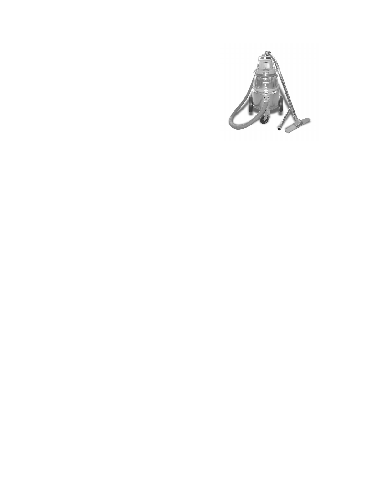
Before turning on the motor: Install the microfilter (#117304-10Felt, #017230-AES Polycomposite, #017220-01-Gore-Tex®), the
small felt sock, on the bottom of the motor by sliding the filter over
the motor bottom, and covering as much of the bottom as the depth
of the filter will permit (photo 1). Be sure the filter's elastic collar
holds the filter snugly in place and is as high up on the motor
Photo 1
Photo 2
bottom as possible.
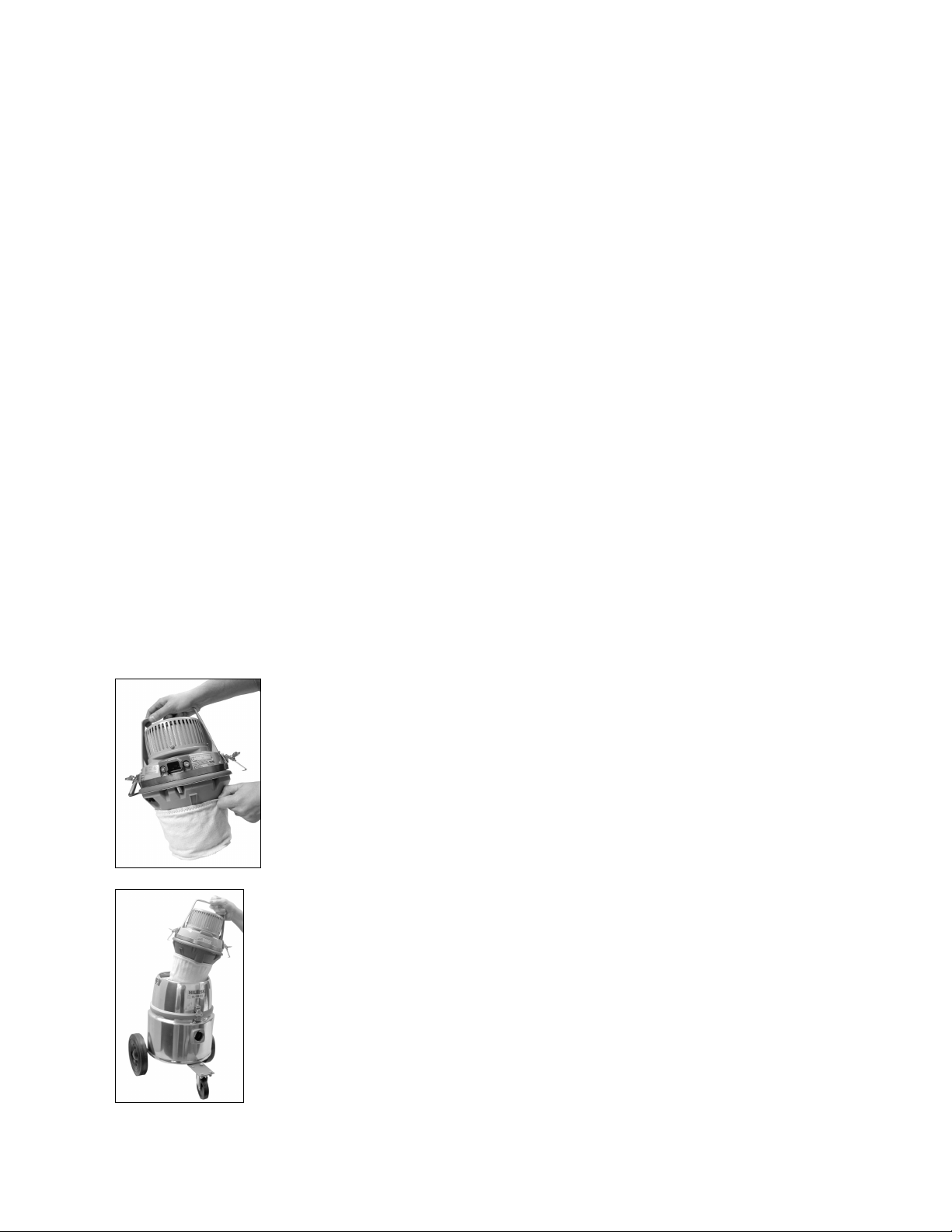
2. Next, mount the HEPA/ULPA filter (#01710104XX /
01710204XX) according to the accompanying bulletin. Place the
motor back in the cavity in the top of the cleaner (photo 2). Fasten
the motor head in place using either the positive twist safety
latches or the standard latches, depending on which option you
purchased.
3
Page 4
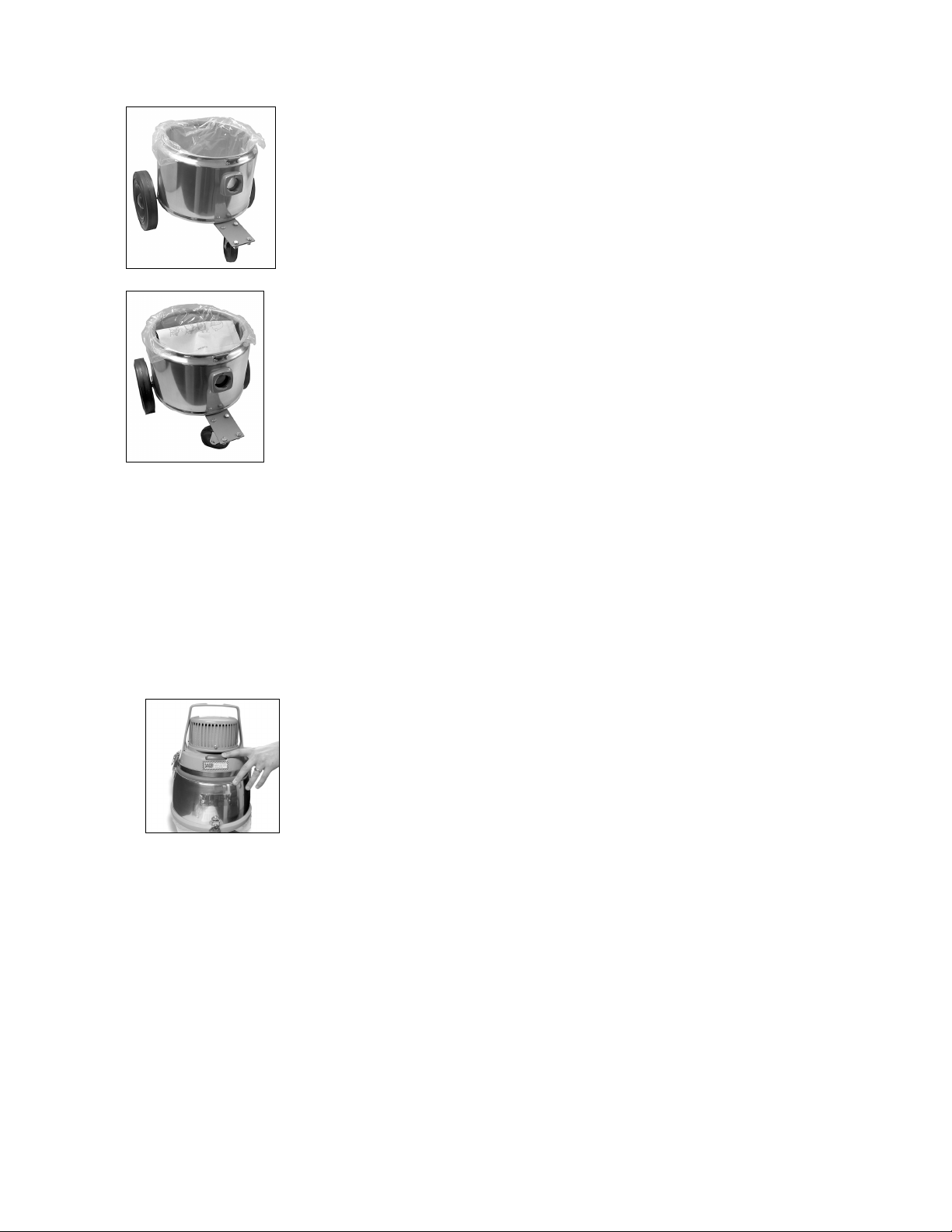
3. Installing the Polyliner and Paper Bag: Twist and release the
two positive twist safety latches, or the standard latches,
depending on your machine. They are located on the body of the
container, front and back. Lift off the top. Open the polyliner and
place in the bottom of the container with its walls flush against the
container sides and lipped under the container inlet (photo 3). The
Photo 3
Photo 4
4. The GM 810 and GM 811 offer a wide variety of hoses and accessories. Consult your
local District Sales Managers or Customer Service Department at (800)-NILFISK for a
list of optional hoses and accessories. No matter what hose option you have chosen, it can
be connected in the following manner. Affix the vacuum hose to the vacuum by inserting
it into the orifice on the lower container. Once it is inserted, rotate the inlet coupler a
quarter turn to lock it into place. Consult your District Manager or the Customer Service
Department if you have any problems attaching the accessories you have purchased.
USING THE MACHINE:
Photo 5
Correct use of the machine: This machine is not a wet/dry vacuum. It is intended for
dry collection only. Do not use this vacuum to pick up liquids, or any wet materials.
EMPTYING:
IF THIS VACUUM CLEANER IS USED TO COLLECT HAZARDOUS MATERIAL,
DO NOT ATTEMPT TO OPEN OR EMPTY ITS CONTENTS WITHOUT PERSONAL
PROTECTIVE CLOTHING AND RESPIRATORY PROTECTION.
excess length of polyliner is draped over the top of the container
and down the outside then rolled at the end to permit the container
clips to close.
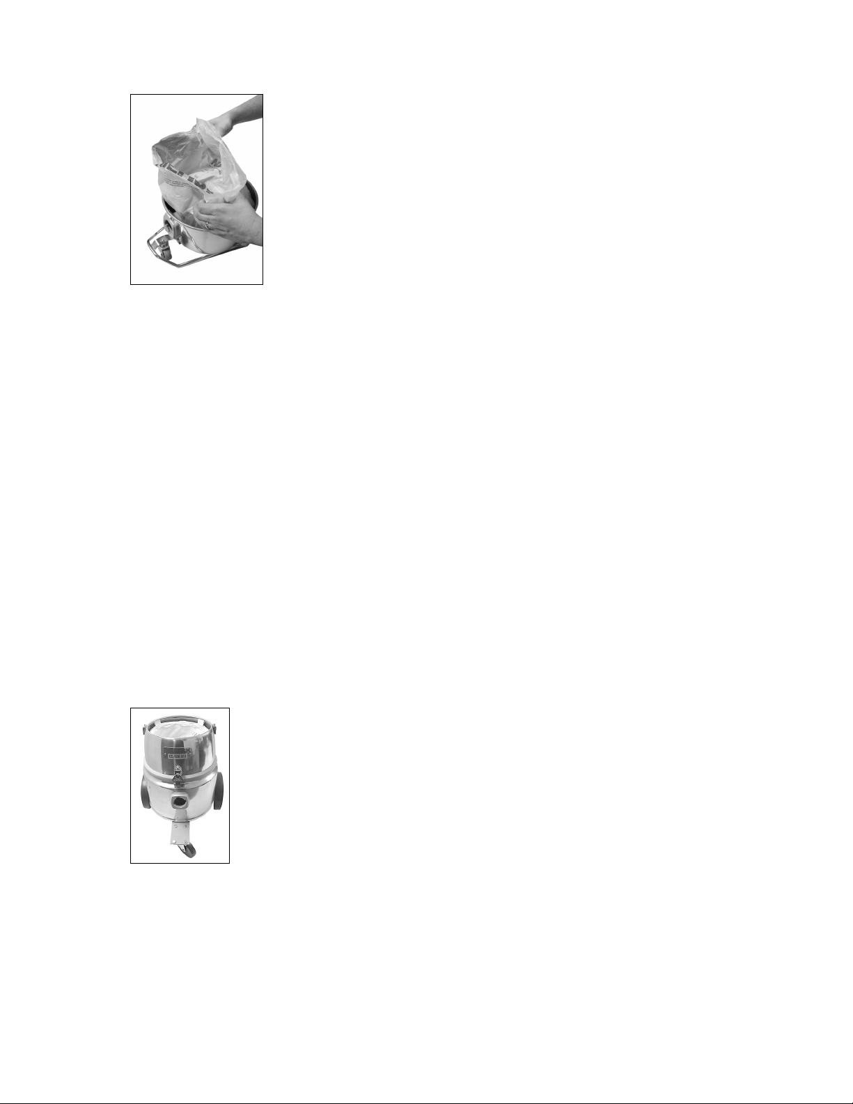
Install a paper bag inside the polyliner according to the
illustrations printed on the paper bag itself (photo 4). Replace the
top container and fasten the two clips.
Note: Polyliners are optional. If you choose not to use a polyliner,
follow the instructions to install the paper bag.
Starting and stopping: Press the gray button on the upper
front portion of the vacuum (photo 5).
4
Page 5
Machine Setup.
To empty the container and its contents, first turn off the motor.
Allow the cleaner to sit undisturbed for at least thirty (30)
seconds. Then twist and release the container clips. Once the
seal is broken, turn on the motor again. This will prevent
ultrafine particles which are still suspended in the air inside the
container from escaping into the work place. Lift off the
container top. Remove the polyliner and paper bag within it
(photo 6). Then seal off the polyliner with the paper bag inside
and install a new polyliner and paper bag according to step 2,
Photo 6
DISPOSAL:
Depending on local regulations, and the composition of the material you have collected,
there can be a requirement for special handling and labeling of the filled and sealed
plastic bags. Consult you local Occupational Safety and Health Administration (OSHA)
and Environmental Protection Agency (EPA) official for details.
MAINTENANCE
Routine Maintenance:
To ensure maximum performance of your Nilfisk vacuum cleaner, be sure to check your
main filter regularly. Your filter may need to be shaken to remove caked dust from time
to time.
Filter Replacement:
To ensure that your Nilfisk vacuum cleaner delivers the years of trouble-free operation
for which it was designed, it is necessary to check and replace filters regularly.
1. Main Filter: The large napped cotton bag which is semi-
permanently mounted inside the container will not require
frequent replacement. The main filter must be replaced when
the cleaner no longer develops powerful suction, yet bags are
not full and other filter components are not clogged. Extend
main filter service life by frequent changes of disposable
polyliners and paper bags (photo 7).
2. Microfilter: This small felt polyester sock, which fits over the motor bottom will
require periodic inspection. Dust will discolor the microfilter. Change the microfilter
as soon as any discoloration is easily noticeable. Do not shake this microfilter since
this can cause liberation of potentially harmful microscopic dust into the air.
Carefully remove and discard with collected debris in the sealable poly bag. If
5
Page 6

equipped with a Gore-Tex microfilter, the same rules for periodic inspection and
disposal apply. The Gore-Tex microfilter has a clamp that holds it in place. The GoreTex filter must be changed when any abrasions, damage or heavy discoloration is
noticed on the surface of the filter (refer to photo 1).
3. HEPA or ULPA Exhaust Filter: This cartridge is mounted on
the top of the motor, outside the container. If the main filter
and microfilter are properly maintained, the glass fiber
element in the exhaust filter should perform satisfactorily for a
minimum of one year. It cannot be renewed or restored. Exact
life will depend upon frequency of use and amount and type
of material collected. Normally four changes of microfilter
equal one change of HEPA/ULPA filters. Remove the
protective metal casing and replace the pleated glass fiber
cartridge according to the accompanying instructions (photo
Photo 8
CAUTION: Use only genuine Nilfisk replacement filter components. The use of
substitute components could pose a grave risk of personal exposure, and will cause all
equipment warranties to be void.
TROUBLESHOOTING
Loss of Power:
1. Make sure the power cord is properly fastened to the motor head, and it is properly
plugged into the socket.
2. Be sure the electrical circuit has not blown a fuse.
3. If the circuit is functioning properly, but there is still no power, contact our Customer
Service Department at (800) 645-3475, extension 2.
Loss of Suction:
If the GM 80 loses suction power during operation, there may be several reasons,
the most likely of which is a full container. Suction loss is gradual as the container fills
with debris. Check to see if there is any blockage or restriction in the hose.
1) Check the condition of the main filter and microfilter (refer to photos) and determine
whether there is an excessive loading of debris. If there is overloading in the main
filter, you can shake it out. If the microfilter is loaded, or there is any other problem
with the microfilter, it needs to be replaced. Call our Customer Service Department at
(800) 645-3475, extension 2 to order replacement filters.
2) If all fails, call our Customer Service Department at (800) 645-3475, extension 2.
8). Cartridges must be replaced more frequently if the cleaner
has had unusually heavy use, or if the various pre-filters have
been neglected.
6
Page 7

GM 810
No. Item No. Description
1 115448-11 UPPER CONTAINER W/
COTTON FILTER
2 121103-29 MOTOR COMPLETE
120 V
3 115447-10 LOWER CONTAINER
4 017091-00 MOTOR HOLD DOWN
RING
5 017092-11 LATCH
6 805521-00 WASHER
7 815406-00 SCREW, 4MM X 5MM
8 705265-10 NUT, 4MM ESN
9 712386-00 SPRING CUP
10 017093-16 KEEPER
11 815407-00 SCREW, 4MM X 10MM
12 705265-10 NUT, 4MM ESN
13 815406-00 SCREW, 4MM X 5MM
14 815406-00 SCREW, 4MM X 5MM
15 815407-00 SCREW 4MM X 10MM
16 805521-00 WASHER
17 017092-11 LATCH
18 017094-10 ADAPTER
19 017093-05 KEEPER
20 815412-00 SCREW 4MM X 6MM
21 705265-10 NUT, 4MM ESN
22 815419-00 RING
23 815418-00 GASKET
24 815417-00 SOCKET
25 814312-00 SCREW
Qty.
1
1
1
1
2
4
4
4
2
2
4
4
4
4
2
4
2
3
3
1
1
1
4
2
2
7
Page 8

GM 811
No. Item No. Description
1 115448-11 UPPER CONTAINER
W/ COTTON FILTER
2 121103-29 MOTOR COMPLETE
120 V
3 017020-00 LOWER CONTAINER
4 017091-00 MOTOR HOLD DOWN
RING
5 017092-11 LATCH
6 805521-00 WASHER
7 815406-00 SCREW, 4MM X 5MM
8 705265-10 NUT, 4MM ESN
9 712386-00 SPRING CUP
10 017093-16 KEEPER
11 815407-00 SCREW,
4MM X 10MM
12 815406-00 SCREW, 4MM X 5MM
13 805521-00 WASHER
14 815406-00 SCREW, 4MM X 5MM
15 017094-01 ADAPTER
16 805521-00 WASHER
17 017092-11 LATCH
18 815407-00 SCREW
19 705265-10 NUT
20 815418-00 GASKET
21 815419-00 RING
22 815417-00 SOCKET
23 814312-00 SCREW
24 017099-43 NUT, 3/8 ESN
25 017024-11 NUT, ESN
26 017847-00 WHEEL
27 017848-00 CASTER, SWIVEL
28 017078-05 CASTER BRACKET
29 017078-15 WHEEL BRACKET
30 017643-00 BOLT 5/16 X 3/4
31 017645-00 WASHER
32 017644-00 NUT, HEX
33 017672-00 WASHER
34 017849-00 HUB CAP
35 017078-11 WHEEL BOLT
36 017877-27 SCREW 8-32 X 1/2
37 017093-02 KEEPER
38 815407-00 SCREW 4MM X 10MM
39 705265-10 NUT, 4MM ESN
Qty.
1
1
1
1
2
4
4
4
2
2
4
4
4
4
2
4
2
3
3
1
1
1
4
2
2
2
1
1
1
4
4
4
4
2
2
2
2
4
4
8
Page 9

HEPA Filter Kit (017104XX)
ULPA Filter Kit (017204XX)
No. Item No. Description
1 217377-01 HANDLE
2 717376-00 FILTER COVER
3 017247-01 HOLD DOWN PAD
4 017009-01 SEAL, FOAM, HEPA
5 813950-00 SCREW
6 821070-00 FILTER BASE
7 017010-05 SEAL,FOAM, BOTTOM
8 017276-31 HEPA FILTER (includes
8 017376-31 ULPA FILTER (includes
item numbers 3, 4, 7)
item numbers 3, 4, 7)
9
Page 10

Filter, Filter Bag and Trolley
No. Item No. Description
1 21573001
1 22394900
2 11693700
3 11641000
4 11730410
5 22132000
6 81585000
EXHAUST WITH DIFFUSER
EXHAUST FILTER WITH MICRO
STATIC DIFFUSER
DIFFUSER FILTERS 2 PCS
MICRO-STATIC FILTER
MICROFILTER
HANDLE COMPLETE
DUST BAG
10
Page 11

Motors
No. Item No. Description
1 12108129 MOTOR GSP 110-120V.UL
1 12108329 MOTOR GSPJ 110-120V.UL
1 12108353 MOTOR GSP 220-240V.UL
1 12108529 MOTOR GSPJ 110-120V.UL
1 12110129 MOTOR GMP 110-120V.UL
1 12112353 MOTOR GMPJ, 220-240V, UL
1 12110329 MOTOR GMPJ 110-120V.UL
10 22232301 TOP HOUSING FOR GS/GM
MOTORS UL APPROVED
11 22410300 SUPPORT RING FOR UL
APPROVED GS/GM MOTOR
12 22231201 BOTTOM HOUSING WITH VALVE
FOR GM MOTOR UL APPROVED
20 22410500 ON/OFF DEVICE FOR GS/GM
MOTORS
21 22410400 LOCKING DEVICE FOR HANDLE
GS/GM MOTORS
22 20705300 THERMO VALVE COMPLETE WITH
PART FOR GM/GS MOTOR HEAD
23 20705400 TWO PRONG SOCKET WITH PARTS
FOR GM/GS MOTOR HEAD
24 20705500 GROUNDED SOCKET WITH PARTS
FOR GM/GS MOTOR HEAD
11
Page 12

Internal Motor Components
No. Item No. Description
1 12125001 MOTOR GSP/GSPJ 100-120V
1 12125002 MOTOR GSP/GSPJ 200-240V
1 12125003 MOTOR GMP/GMPJ 110-120V
1 12125005 MOTOR GMP/GMPJ 220-240V
2a 22130500 WIRE KIT/THERMO SWITCH
FOR UL APPROVED MOTOR
2b 22130501 INTERNAL WIRE AND
CAPACITOR
3 22131100 ON/OFF SWITCH 1-POLE
4 22131200 ON/OFF SWITCH 2-POLE
10 22231100 MOTOR SUSPENSION-
PHILLIPS
11 22365300 SOUND ABSORBER AND
GASKET
12 22399800 GASKET FOR INLET
12
Page 13

Power Cords
No. Item No. Description
1 21827400 9.3M CORD AWG18/3
1 21952200 9.3M CORD AWG18/2
10 22361000 BRACKET W/ SCREWS FOR
CORD
11 22131600 BRACKET WITH SCREWS
13
Page 14

Accessories
1
2
3
4
No. Item No. Description
1 11574100 HOSE 10' W/ INLET 38MM
1 11574000 HOSE 6'6" W/ INLET 38MM
2 11343900 HOSE EXTENSION 10'
2 11343700 HOSE EXTENSION 6'6"
3 11027200 STRAIGHT STEEL WAND 22"
4 10944000 CURVED STEEL TUBE
5 1403816020 WHEELED FLOOR NOZZLE 16"
6 11476000 16" CARPET NOZZLE
7 11476101 16" BARE FLOOR NOZZLE
8 10950200 ADJUSTABLE ROUND BRUSH 3"
8 10950201 ADJUSTABLE ROUND BRUSH
WITH RED BRISTLES 3"
8 10950202 ADJUSTABLE ROUND BRUSH
WITH GREEN BRISTLES 3"
8 10950203 ADJUSTABLE ROUND BRUSH
WITH BLUE BRISTLES 3"
9 70945300 METAL FURNITURE NOZZLE
10 80956200 RUBBER CONE 8"
11 10949500 CREVICE NOZZLE
12 1710100 45 DEGREE CREVICE NOZZLE
5
6
7
8
9
10
11
12
14
Page 15

TECHNICAL SPECIFICATIONS
Motor type, grounded GMPJ
Tank capacity 3 1 /4 gallons
Voltage @ 60 Hz. 110-120/220 volt
Paper bag capacity 2 1 /4 gallons
Current draw 9 amps
Filter area** 1477 square inches
Power watts 1100
Dimensions (l x w x h) 14x12x16 inches
Waterlift*, max. 102 inches H2O
Weight without accessories 11 lbs.
Airflow, max. 87 cfm
Cord length 30 feet
Air performance 250 air watts
*With pressure relief valve inactive
** Filter area included paper bag, main filter, microfilter, HEPA
CONTACT INFORMATION
Nilfisk-Advance America, Inc.
300 Technology Drive
Malvern, PA 19355
Phone: (610) 647-6420
Fax: (610) 647-6427
questions@nilfisk-advance.com
www.pa.nilfisk-advance.com
15
 Loading...