

Page 1
CONTRACTOR DIESEL
Instruktionsbog ............................. 1 - 12
Instruksjonsbok............................. 13 - 24
Instruktionsbok ............................. 25 - 36
DA
SV
NO
Instruction manual........................ 37 - 48
Betriebsanleitung .......................... 49 - 60
Manual d’Instructions.................... 61 - 72
Gebruikershandleiding.................. 73 - 84
EN
FR
DE
NL
2003-11-11
Page 2

Congratulations!
We’d like to say, “Thank You” for choosing the
CONTRACTOR DIESEL. This instruction manual is provided with your new High Pressure
Washer to ensure that you obtain the best
results, in the safest manner, with your new
machine.
IMPORTANT
This machine is a High Pressure Washer,
capable of producing 2600 psi (180 bar). Read
this manual completely, befare operating the
machine. A complete understanding of the
material in this manual will help you avoid
possible injury or damage to other objects, as
well as damage to the machine, itself. It’s also
important that you read the Ruggerini engine
manual provided, before you begin to use this
machine.
Sincerely,
ALTO Danmark A/S
Contents EN
1.0 Safety ..................................................... 38
1.1 Warning Refilling with diesel ............ 38
1.2 Asbestos ......................................... 38
2.0 Motor Protection Device ..................... 39
3.0 Key photo’s ........................................... 39
4.0 Application ............................................ 40
4.1 Handling and transport. .................. 40
5.0 Standard equipment ............................ 40
6.0 Accessories. .......................................... 40
7.0 Functional description ........................ 41
7.1 High pressure pump . ..................... 42
7.2 Burner system ................................ 42
7.3 Diesel engine ................................... 42
7.4 Spray lance. .................................... 42
8.0 Connections ......................................... 43
8.1 High pressure hose ........................ 43
8.2 Spray handle and lance .................. 43
8.3 Water connection ............................ 43
8.4 Suction mode .................................. 43
8.5 Use of detergents ........................... 43
8.6 Fuel for burner ................................ 43
8.7 Fuel for engine ................................ 43
9.0 Operating instructions ........................ 44
9.1 Start-up procedure.......................... 44
9.2 Cold water operation ....................... 44
9.3 Hot water/steam operation ............. 44
9.4 Adjustment of pressure and
water volume ................................... 44
9.5 Shutdown......................................... 44
10.0 Storage/frost proofing ........................ 45
11.0 Model tag ............................................... 45
12.0 Maintenance .......................................... 46
12.1 Water inlet filter ................................ 46
12.2 Couplings/connectors ..................... 46
12.3 Oil change, pump/engine ................ 46
12.4 Burner fuel filter ............................... 46
12.5 Descaling......................................... 46
12.6 High pressure nozzle care ............. 47
13.0 Warranty ................................................. 47
14.0 Troubleshooting .................................. 48
15.0 Technical data ...................................... 48
37
Page 3
1.0 Safety EN
Your CONTRACTOR DIESEL washer has
been developed and manufactured in
accordance with the latest working safety
regulations.
Caution! However, to prevent possible personal accidents or damage to any other product,
we advise you to read carefully through this
section on safety precautions before you
operate your washer for the first time.
General safety precautions
1. Always use both hands for operating spray
equipment to maintain complete control of
the lance.
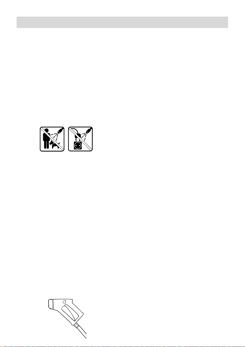
2. Water jets should never be directed towards
people, pets, electrical wiring or the ALTO
CONTRACTOR DIESEL machine itself.
3. Always switch off engine during work breaks.
4. Connect or disconnect the high pressure
hose ONLY when the engine is stopped.
5. Use only those hoses and nozzles
specified by ALTO.
6. The machine should only run for a
maximum of five minutes once the spray
handle has been released (the pump then
circulates the water internally and the
machine will overheat unless stopped after
5 minutes).
7. The pump is equipped with a high pressure
relief safety valve. This adjustment, like any
others that require the use of tools, should
only be made by a trained service technician.
8. Operating the machine when it, or any
attachments are frozen, is dangerous. Be
sure everything is thawed before operating
the machine.
9. Manufacturer’s instructions for the use of
any detergents should be carefully
observed at all times.
10. During work breaks, or any time lances or
accessories are changed, the spray handle
must be secured by rotating the safety
knob into position O.
I
0
11. The machine must not be used in
surroundings with risk of fire or explosion.
12. Exhaust from engine and burner contains
poisonous carbon monoxide gases. Avoid
inhalation of exhaust gases. Never run the
machine in a closed garage or confined area.
13. To prevent fire hazards and to provide
adequate ventilation, keep the engine at
least 1m/3ft away from buildings and other
equipment during operation.
14. Do not place flammable objects such as
gasoline, matches, etc., close to the
machine while it is running.
15. Allow only properly instructed personnel to
use the machine.
16. Never let children operate your
CONTRACTOR DIESEL at any time.
17. Don’t use the machine if important parts of
the equipment are damaged - i.e. safety
devices, high pressure hoses, spray
handle, cabinet.
1.1 Warning
Refilling with diesel:
Always stop the Ruggerini engine and allow it to
cool off for at least two minutes before filling with
diesel. Avoid spilling diesel. If diesel
nevertheless is spilled while refilling, the engine
must not be started before the spilled diesel has
been removed. If the machine is located in a
trailer, any diesel spillage must be removed
before restarting the machine. Never use an
open flame near the machine. It is forbidden to
smoke while refilling with diesel. Read the instruction manual for the Ruggerini engine
carefully.
NOTE: Never run the machine in a closed
room. The exhaust gases are dangerous
1.2 Asbestos
To avoid release of asbestos fibers into the
environment, ALTO strongly recommends that
this machine not be used for cleaning of
materials or surfaces of materials containing
asbestos. If this machine is to be used for
asbestos removal do so only in complete
compliance with approved goverment guidelines
and/or procedures.
38
Page 4

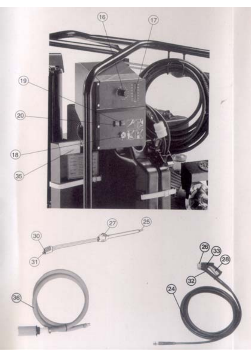
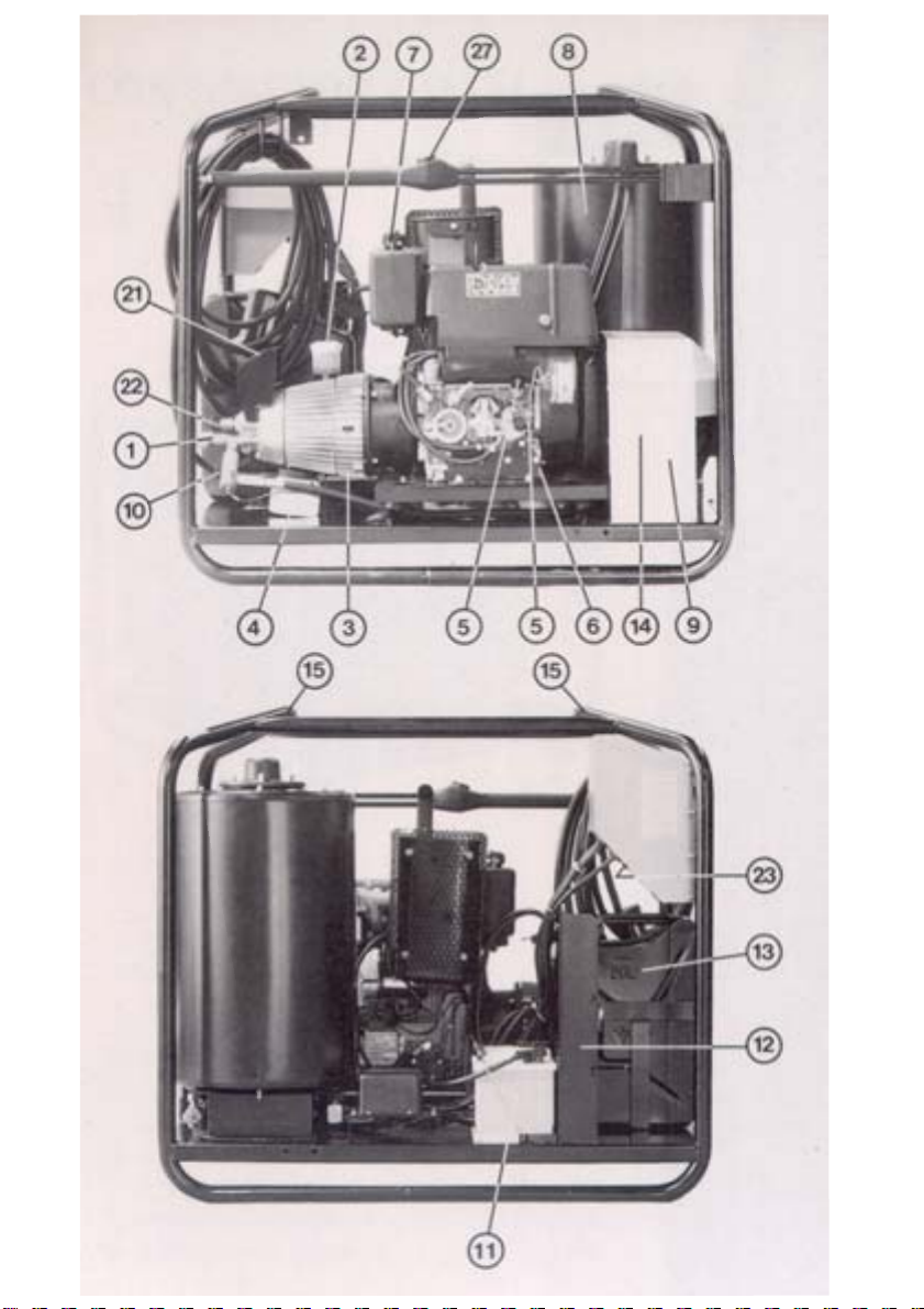
2.0 Motor Protection Device 3.0 Key photo’s EN
The diesel engine is equipped with a protection
device called ”Oil Alert”, which stops the engine
if the oil level is insufficient. If this occurs, check
the engine for leaks, and after making sure the
machine is level, refill it to the proper level. The
engine can then be restarted.
(See drawing on the cover)
1. Water inlet and filter
(quick-coupler for supply hose)
2. Pump oil level inspection and fill cup
3. Oil drain plug for pump
4. Sludge container
5. Engine oil dipstick and filler tube
6. Oil drain plug for diesel engine
7. Diesel filling cap
8. Burner coil
9. Fan for burner
10. High pressure outlet (male quickconnector)
11. Battery
12. Container rack for detergents
13. ”Jerry-can” for heating oil
14. Burner fuel filter
15. Frame lift points
16. Thermostat
17. Thermometer
18. Key for electric start
19. Battery charge control
20. »Oil Alert« (see section 2.0)
21. Pressure gauge
22. Knob for adjustment of water volume
23. Fuse (protection of electronic unit)
rating 1.25 AT
Double spray lance with hose
24. High pressure, steam-capable hose
25. Male connector
26. Quick coupler
27. Pressure adjustment
28. Release trigger
29. Standard double spray lance
30. Low pressure nozzle
31. High pressure nozzle
32. Spray handle
33. Trigger safety knob
35. Data plate
36. Inlet hose w. filter
39
Page 5

4.0 Application EN 6.0 Accessories EN
ALTO’s diesel powered high pressure washers
can be used for all outdoor cleaning jobs for
which steam, hot or cold water is used.
Detergents can be used (see section 8.5)
4.1 Handling and Transport
When handling the machine with a fork lift truck,
be sure the forks extend completely under the
machine to prevent tipping. When lifting the
machine, a sling may be wrapped around the
upper frame tubes for lifting. Ensure that
personnel aren’t under or near the machine
during lifting. When transporting the machine in
a truck or trailer, be sure that it is secured
against sliding or tipping.
5.0 Standard equipment
The machine is delivered with a double lance
and a spray handle with high pressure steamcapable hose. The low pressure tube (pos. 30)
is fitted with a flat jet nozzle 6530* and the high
pressure tube (pos. 31) with a flat jet nozzle
1506*.
*) The first two digits of the nozzle number refer
to the spray angle, in degrees. The last two
digits indicate the water flow in l/min. at a pressure of 20 bar and a temperature of 20°C.
In order that you may make the most of your
high pressure washer, ALTO has produced a
very comprehensive accessory program,
including a pneumatic tire kit especially for the
CONTRACTOR DIESEL.
Please feel free to contact your ALTO supplier
for further information.
The actual nozzle orifice size are 0.63” (1.6
mm) for the nozzle 1506 and 0.142” (3.6 mm)
for the nozzle 6530. NEVER replace the
nozzles with those of a smaller size.
Maximum working pressure and temperature
rating are embossed on the ALTO hose. Use
only ALTO high pressure, steam-capable
hoses. In case of damage to your hose, DO
NOT attempt to repair the hose yourself! The
thrust (backwards turned force) on the nozzle
is approximately 12.5 ft/Ib (55 N).
Since the nozzles are mounted at an angle to
the lance, there will be a torque effect at the
handle when spraying. Always use two hands
when operating the spray equipment.
40
Page 6
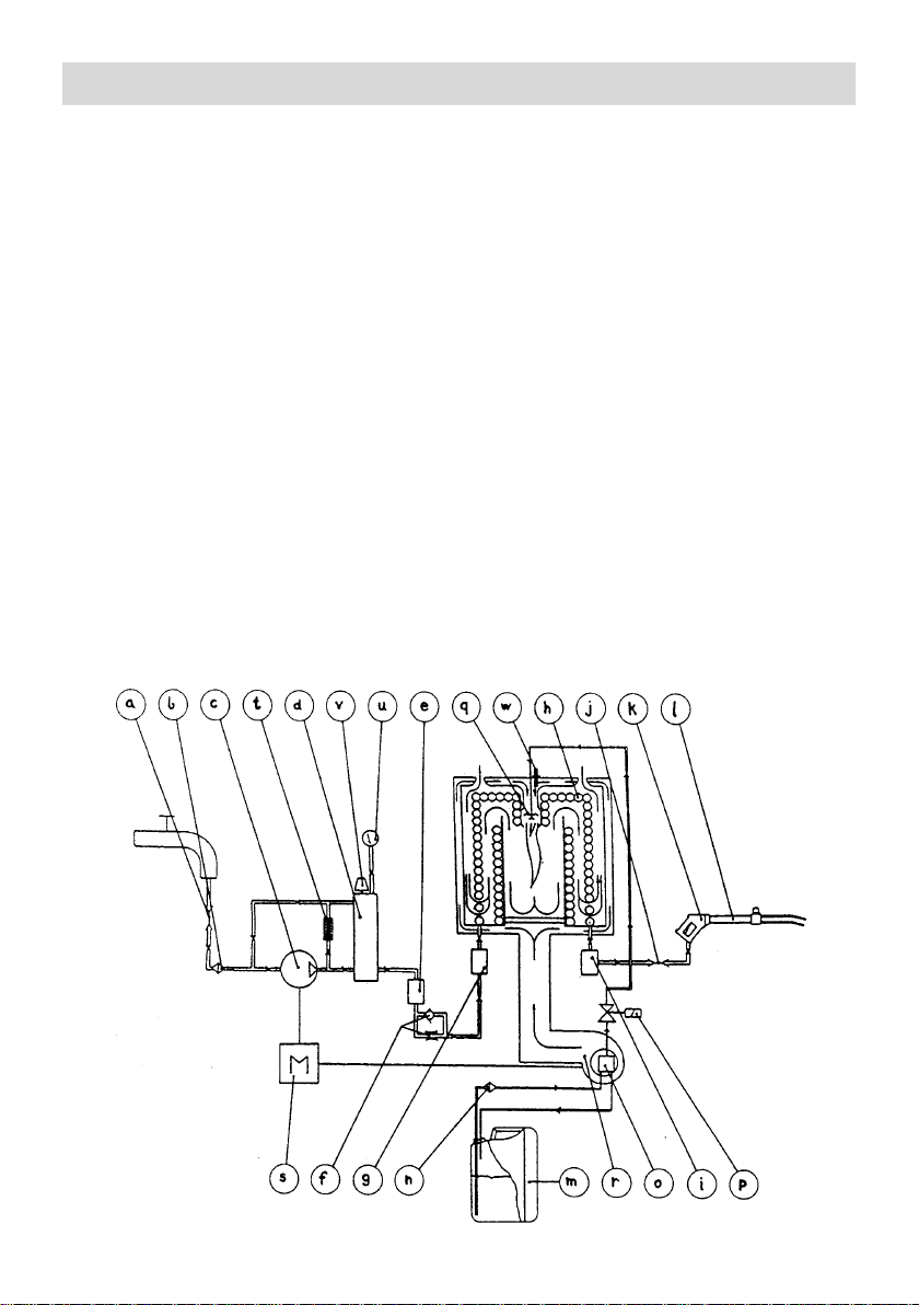
7.0 Functional description EN
The water passes from the inlet connector (a)
through a water filter (b) and into the high pressure pump (c). The high pressure water is
passed through the regulating unloader
(recycling valve) (d) and the first flow control
(e) to the throttle valve (f) and through the
second flow control (g) into the burner-coil (h).
Here the water is heated to the required
temperature. At the outlet of the burner-coil the
hot high pressure water passes the temperature sensor (i) and proceeds through the outlet
connector (j) to the spray handle (k) and double
spray lance (1.) The fuel is drawn from the fuel
tank (m) through the fuel filter (n) by the fuel
pump (a). The fuel pump passes the fuel
through the magnetic solenoid valve (p) to the
fuel nozzle (q) where it is ignited. The
combustion in the burner is monitored by the
flame sensor (w) and is supplied with air from
the fan (r), which together with the high pressure pump (c) are driven by the diesel engine
(s).
a Inlet quick-connector
b Water filter
c High pressure pump
d Unloader/regulator (recycling valve)
e Flow switch
f Throttle valve
g Flow switch
h Burner coil
i Temperature sensor
j Outlet quick-connector
k Spray handle
I Double spray lance
m Fuel tank ”Jerry-can”
n Burner fuel filter
o Fuel pump
p Magnetic solenoid valve
q Fuel nozzle
r Blower for burner
s Diesel engine
t Safety valve (internal)
u Pressure gauge
v Water volume adjustment
w Flame sensor
41
Page 7

Functional description EN
7.1 High pressure pump
An unloader (recycling valve) and a safety
valve are located on the pressure side of the
high pressure pump. The unloader recirculates
the water to the suction side of the pump when
the spray handle is closed or if a nozzle is
blocked. The safety valve is adjusted to approx.
25 bar (360 psi) above the working pressure.
The high pressure pump should not run idle for
more than 5 min., since the water inside the
pump gets hot while it is recirculating. The
unloader ensures there is no pressure in the
pump when the engine is stopped. The unloader
and safety valve are adjusted and sealed at the
factory. DO NOT attempt to change this
adjustment.
7.2 Burner system
The burner is controlled by electronic circuits
which include a thermostat, flow switches to
evaluate water flow and a sensor to monitor the
flame. Water temperature is regulated by the
thermostat. Flow switches ensure there is
water flowing through the machine before
allowing the burner to light. These devices are
connected to a printed circuit board which
activates a magnetic solenoid valve on the fuel
pump to supply or stop fuel flow to the burner.
There are two flow switches installed, for
additional safety and protection of the burner
coil. The circuit board ensures that they agree
before allowing fuel to flow to the burner. The
flame sensor is a separate circuit which stops
the machine if there is no flame in the burner in
hot water or steam mode.
It is important for the life of the fuel pump, that
the machine is not allowed to run in the hot
water or cold water mode, with empty fuel tank.
If the burner stops working unexpectedly,
check the fuel level in the tank and refill it if
necessary.
7.4 Spray lance
The double spray lance is fitted with 2 nozzles,
a high pressure nozzle and a low pressure
nozzle. When the pressure adjustment valve
(pos. 27) is completely closed only the high
pressure nozzle is used. Both the high pressure nozzle and the low pressure nozzle are
used when the pressure adjustment valve is
opened. Nozzles with smaller orifice size (0)
than described in section 5.0 must not be
mounted on the lance.
7.3 Diesel engine
A description and operating/maintenance
instructions for the Ruggerini engine will be
found in the Ruggerini manual provided with the
CONTRACTOR DIESEL. Please read this
before starting up. The throttle limit of the engine
has been adjusted by ALTO, so that the max.
number of revolutions corresponds to the max.
pressure of the pump. The adjustment is
sealed. This adjustment must not be changed.
42
Page 8

8.0 Connections EN
8.1 High pressure Hose
Connect the high pressure, steam-capable
hose (pos. 24), to the outlet quick-coupling
(pos. 10) on the machine front. Use only original
ALTO high pressure, steam-capable hoses.
The hose should not be exposed to abuse,
such as knots, kinks, contact with sharp
objects or external heat sources, as this may
cause bursting. Only ALTO high pressure,
steam-capable hose should be used for
extension hoses. The extension hoses should
not exceed a total maximum length of 300 ft
(100 m).
8.2 Spray handle and lance
Check the male connector (pos. 25) of the
spray lance for foreign material. With one hand,
grasp the quick coupler fitting (pos. 26) and pull
it forward. Insert the male connector of the
lance or accessory into the spray handle quickcoupler, and release the fitting. Pull the lance or
accessory forward to ensure it is correctly and
tightly installed, before operating the machine.
NEVER release a lance or accessory while
water or steam are coming from the nozzles of
the lance or accessory.
8.3 Water connection
The water inlet connection is at the front of the
machine, on the pump (pos. 1). Before
connecting the water supply hose, it should be
flushed to remove any impurities. The machine
can be connected directly to a pressurized
water supply or a tank. The inlet pressure must
not exceed 15 bar (218 psi) and the water
temperature must not exceed 35°C (95F°) .
When the machine is connected to a water
supply with back-flow-preventer the water
supply hose must be at least 6 m (20 ft) in
length. If there are impurities in the water
source, it is advisable to provide additional
filtration in the inlet line. Ask your ALTO
representative about the filters and filters
available for your CONTRACTOR.
8.4 Suction Mode
The machine is self priming, when used from a
tank or stream, etc. The inlet hose must be filled
with water before starting up. The self priming
height depends on the water temperature. Max.
self priming height of 5 m (17 ft) is reached with
cold water (up to 8°C/47°F). Foreign material in
the water supply can damage your machine. If
there is a risk of foreign material in the water
source entering the supply hose, a filter or filter
must be mounted.
8.5 Use of Detergents
The machine is supplied as standard without
detergent injection equipment. In self priming
mode, detergents must not be added to the feed
water (pos. 1), and thereby circulated through
the pump. If your work requires detergents,
they may be added through the optional
external (downstream) injector available from
your ALTO supplier.
NOTE! Certain organic solvents are aggressive
to rubber and plastics used in high pressure
hoses and must therefore not be used. Using
detergents outside the range from 4.0 - 10.0
pH, will result in a loss of working life for your
high pressure hose and seals in the spray
handle, lances and other accessory. Follow
precisely the directions printed on the packing
when using detergents.
8.6 Fuel for burner
Use ONLY ”heating oil”, kerosene or diesel fuel
in the ”Jerry-can” fuel tank for the burner. DO
NOT put gasoline in the burner fuel can!
8.7 Fuel for engine
Use only clean auto-diesel for the Ruggerini
engine.
43
Page 9

9.0 Operating instructions EN
9.1 Start-up procedure
1. Check that the pump oil level is between the
MIN. and MAX. marks (pos. 2). Oil type:
ALTO Pump Oil 100.
2. Check the oil level on the Ruggerini engine.
Oil type: Choose oil type in accordance with
the instructions in the Ruggerini manual.
3. Run water through the inlet hose before
connecting in order to remove possible
impurities in the hose. Any water supply valve
must be fully open in order to provide sufficient water supply.
4. Open the small venting cap on the ”Jerrycan” if you intend to operate in hot water or
steam mode.
5. Turn the thermostat (pos. 16) to the blue field.
6. Start the Ruggerini engine as described in the
enclosed operating instructions. The key for
the electric start has the following 3 positions:
1 ”0” off
2 ”I” run
3 the startkey will return to position 2
when released.
7. Turn the trigger safety knob (pos. 33) to
position 0 and squeeze the trigger of the
spray handle (pos. 28) allowing water to flow
until the stream is steady.
8. When the engine is warmed up, check that
max. working pressure does NOT exceed
the maximum allowable pump pressure. This
can be taken from the pressure gauge and
must not exceed 180 bar (2600 psi). Overload will reduce the life of the machine. (See
section 14.0).
9.2 Cold water operation
After the starting up procedure the machine is
ready for cleaning with cold water.
9.3 Hot water/Steam operation
Hot water:
Adjust the thermostat (pos. 16) to the required
temperature, 30-95°C (86-200°F).
Steam:
a) Adjust to temperatures above 95°C (200°F)
ONLY with the trigger on spray handle
released.
b) Turn the water volume adjustment knob (pos.
22) completely in (fully clockwise).
c)Adjust the thermostat to the required
temperature, 95-150°C (200-302°F).
44
d) Start the machine, if stopped, and activate the
spray handle to start the burner.
IMPORTANT: For safety reasons it is important
that instruction (a), above, always be followed!
Note: If the engine stops immediately after
having been started up, it should be checked
whether the throttle control is set at idle speed.
If it is, the throttle control should be adjusted to
full speed.
9.4 Adjustment of pressure and
water volume
High pressure/volume
In order to achieve maximum working pressure
the pressure adjustment knob (pos. 27) on the
lance should be turned all the way in (clockwise
until completely closed) and the volume
adjustment knob (pos. 22) situated on the front of
the pump should be turned all the way out
(counterclockwise). The water volume is infinitely
variable up to the max. capacity of the machine.
Low pressure/volume
To reduce the working pressure, turn the pressure adjustment knob (pos. 27) on the lance,
counterclockwise until the desired result is
achieved. To reduce the water pressure AND
volume, release the trigger (pos. 28) or stop the
machine. Turn the volume adjustment knob on
the front of the pump, clockwise, reducing water
flow and volume. Test the results, and repeat
the process until you have achieved the results
you wish. By varying the settings of the pressure adjustment knob on the lance, and the
volume adjustment knob on the pump, you may
obtain pressures from 4 bar (60 psi) to 180 bar
(2600 psi), and water flows from 6 l/min. (1.6
US gpm) to 20.5 l/min. (5.4 US gpm).
9.5 Shutdown
WARNING: Danger of burn
Do not disconnect the high pressure hose until
you have completed the following steps (risk of
injury):
1. Turn the thermostat (pos. 16) to the blue field.
Spray cold water until the water temperature
is under 50°C (122°F). Disconnect or turn off
the water supply.
2. Squeeze the trigger of the spray handle for a
short time to empty the system of water.
3. Stop the diesel engine. (See instructions for
the Ruggerini engine).
4. Disconnect the high pressure hose.
Page 10

10.0 Storage/frost proofing 11.0 Model tag
It is advisable to store the machine in a frost
proof place between operations. If this is not
possible the machine should be protected in the
following way:
1. Disconnect the inlet hose. Remove the lance
(pos. 29) and empty it of water.
2. Ensure that the thermostat is set in the blue
field, and start the machine, allowing it to run
with the spray handle opened until it is empty
of water.
3. Place a suction hose in a bucket with 6-8 l
(1.5-2 gallons) anti-freeze.
4. Place the spray handle (without spray lance)
above the bucket, open the spray handle so
that the antifreeze can circulate. Open and
close the spray handle a few times.
5. Remove the suction hose from the bucket
and allow the machine to pump all of the
solution back into the anti-freeze container.
The anti-freeze can be re-used, but keep in
mind that it is slightly diluted with water each
time this is done.
Important:
To avoid damage always ensure that the
washer, the hoses and the spray lance are
unfrozen before restarting. Place the washer
and the accessories in a warm environment for
some time before starting up.
This machine has the model name,
”CONTRACTOR DIESEL”. The model designation is printed on a decal positioned on the
control panel and on the data plate. The data
plate provides the following important
information:
1. Model designation
2. Production code (year and week) 3. Serial
number
4. Pump pressure
5. Water volume
6. Max pressure
7. Max temperature
8. Manufacturer
45
Page 11

12.0 Maintenance EN
12.1 Water inlet filter
The inlet water connection (pos. 1) contains a
filter to prevent impurities entering the highpressure pump. This filter must be inspected at
regular intervals, and cleaned as required. The
filter can be removed after removing the quick
coupling.
NOTE:
To avoid serious damage to the rubber gasket,
the quick coupling should be tightened only
gently.
12.2 Couplings/connectors
To prevent leakage and damage to connectors/
couplings on hoses, spray handle, machine and
spray lance, these need to be cleaned
occasionally and lightly lubricated with oil or
grease.
12.3 Oil Change
The oil level must be checked at regular
intervals (see section 9.1). The oil should be
changed according to the following guidelines:
1. OIL CHANGE FOR PUMP
Change the oil after 1000 hours of operation, or
when the oil appears ”milk-white”. Take off the
cover of the oil glass (pos. 2). Unscrew the oil
drain plug on the bottom of the pump (pos. 3).
Drain the oil and then clean the dirt off the drain
plug. Screw the plug in and top up the pump
with fresh oil through the oil glass.
The pump holds approximately 1 quart (1 litre)
of zincless hydraulic oil. From ALTO the pump
is filled with ALTO Pump Oil 100. When refilling
and changing the oil this or a substitute with the
following specifications may be used:
Zincless Hydraulic Oil
ISO no. 100
Viscosity Index (VI) min. 130
Pour Point below -30°C
SLUDGE CONTAINER
It is normal for a small amount of oil and water
to get past their seals. This oil/ water is
collected in a sludge container (pos. 4). Empty
the container before it has filled completely. This
oil/water mixture must not be re-used in the
pump.
2. ENGINE OIL CHANGE
Refer to the Ruggerini engine manual for breakin and normal operating oil change
requirements. Carry out first oil change after i0
hours of operation and then every 100 hours.
Not less than once every six months, however.
NOTE: Protect the environment by properly
disposing of used pump and engine oil.
12.4 Burner fuel filter
To prevent foreign material from entering the
fuel pump a filter (14) is fitted between the fuel
tank and the fuel pump. This filter must be
changed regularly, the frequency depends on
the purity of the fuel. Replacement of the filter
each year is recommended. See also diagnosis
of faults and repair 16.0.
12.5 Descaling
After a period of operation depending on the
hardness of the water, scale deposits will begin
to accumulate in the heating coil. These
deposits will reduce the effect of the water
heating system and increase the fuel
consumption. The machine should therefore be
descaled regularly. If the machine adjusted on
maximum water volume will not heat cold water
(8°C/47°F) to 70°C (158°F) within three
minutes, the burner or coil require servicing or
descaling, as follows:
NOTE:
Always carry out the descaling according to the
instructions supplied with the descaling product:
1. Disconnect the high pressure hose
2. Place an inlet hose in a container of at least
10 l (3 gallon) capacity, with a solution of
recognized descaling product (i.e. ALTO
STONEX), and water in the recommended
percentage (not normally over 10% of the
descaling product ratio 1:10). Ask your ALTO
distributor for recommendations.
3. Start the machine.
4. Switch off the machine when the water from
the outlet fitting is colored by the scale remover.
WARNING! The solution can be caustic. Note:
Air must in no circumstances get into the system; therefore the container with scale remover must never be emptied completely.
46
Page 12

Maintenance EN 13.0 Warranty EN
5. Leave the machine for 20 minutes.
6. Start the machine and pump the used solution
into a container for proper disposal.
7. Immediately connect a fresh water supply
and turn it on.
8. Start the machine, let it work for 5-10
minutes, until all the scale remover is out of
the system.
9. If necessary, repeat the procedure from
instructions 2 to 8.
12.6 High pressure nozzle care
An obstructed nozzle causes an increase in
pump pressure. Immediate correction is
required.
1. Stop the machine and dismount the spray
lance.
2. Clear the nozzle obstruction with a ALTO
nozzle tool No. 6401654.
WARNING: This operation must be performed ONLY with the lance removed from
the machine.
3. Backflush the spray lance with water. Use
the spray handle, pressing it towards the
nozzle protection cap on the front of the
spray lance.
4. If the pressure is still too high, repeat items 13, or remove the nozzle from the lance for
cleaning.
ALTO Danmark A/S warrants against defects in
the supplied product for a period of 12 months
from the purchase date subject to the following
conditions:
- that defects are attributable to material or
manufacturing flaws. (Items which require
replacement due to normal wear and tear,
abuse or misuse are not included in this
limited warranty).
- Repairs required due to improperly performed
service or repairs, are excluded.
- Repairs required due to the use of non-ALTO
parts or accessories, are excluded.
- Repairs required by operation of the machine
in a manner not prescribed in this Instruction
Manual.
The engine warranty is as described by, and in
accordance with the practices and policies of
Ruggerini Motor Company. See the Ruggerini
documents for details.
47
Page 13

14.0 Troubleshooting EN
Fault Cause Repair
The engine fails to start Insufficient diesel supply Refill diesel tank.
Working pressure too high Nozzle partly blocked Clean the nozzle. See section 12.6.
Working pressure Valve for regulation of Open fully the valve for regulation of
too low water volume is not water.
Irregular working Air in the pump Repeat the venting procedure.
pressure Inlet filter/filter blocked Clean the filter. See section 12.1.
In suction mode: Excessive suction head Read section on suction mode (8.4).
No working pressure Nozzle blocked Clean nozzle. See section 12.6.
The burner does not Insufficient fuel supply Refuel.
ignite Fuel filter blocked Clean the filter. See section 12.4
Should faults occur other than those mentioned above, please contact the nearest ALTO service
organization *) IMPORTANT NOTE: To avoid damage to the electronic systems, the battery
connecting cables must be removed when recharging the battery.
Battery run down Recharge the battery*)
Fuse blown Exchange fuse. See section 3.0.
The pump is frozen Let the pump thaw.
adjusted to max pressure Turn counterclockwise.
Nozzle worn Replace nozzle.
Motor speed too low Contact ALTO service technician.
Insufficient water supply Change to a water supply with greater
from the water works output. If this is not possible; turn the
valve for regulation of the water volume
clockwise, until the machine works smoothly.
or excessively hot water
Nozzle partly blocked Clean nozzle. See section 12.6.
No water Check the water connection.
Unloader (recycling valve) Allow the machine to thaw.
frozen See section 10.0.
High pressure hose/ Allow the high pressure hose/
spray lance frozen spray lance to thaw.
15.0 Technical data EN
Model CONTRACTOR DIESEL
Pump pressure, max. bar/psi 180/2610
Water volume at min/max pressure l/min-USgpm 20,5/19 - 5.42/5
Max. temperature of inlet water °C/°F 35/95
Heating power kW/Kcal 115/98.200
Nozzle, spray angle degrees (05) 15/65
Self-priming, max. lift m/ft 5/16.5
Engine Ruggerini MD 151
Rated effect kW/hp 12/16.3
Start system Electric start
Battery V/Ah 12/50
Diesel consumption, max. pressure l/h-USgph 3.0-0.79
Fuel consumption at 60°C/140°F 1) l/h-USgph 7.5-1.98
“Jerry-can”, capacity l/Usg 20/5
Sound power level (LWA) of the machine measured in accordance with ISO 3746: 112 dB(A).
Sound pressure level (L
1
) Delta t= 52°C/126°F
This machine has been manufactured in accordance with the EMC directive 89/336/EEC inclusive of subsequent
amendments.
Specifications are subject to alterations.
) measured in accordance with ISO 11202 [DISTANCE 1m] [FULL LOAD]: 100 dB(A).
PA
Page 14
Page 15
Page 16

6229952 (02.2003)
Printed in Denmark
Copyright © 2003 ALTO Danmark A/S
ALTO Danmark A/S
Industrikvarteret
DK-9560 Hadsund
Tel.: +45 7218 2100
www.alto-online.dk
 Loading...