

Page 1
American-Lincoln
Technology
OPERATOR’S
MANUAL &
PARTS LIST
Beginning with Serial Number: 683082
READ THIS BOOK
This book has important information for the use and safe operation of this machine. Failure
to read this book prior to operating or attempting any service or maintenance procedure to
your machine could result in injury to you or to other personnel. Damage to the machine or to
other property could occur as well. You must have training in the operation of this machine
before using it.
All directions given in this book are as seen from the operator's position at the rear of the machine.
ATS 46/53 BATTERY
SWEEPER/SCRUBBER
ATS
4
6
/5
3
ISO 9001
U
®
L
#
FILE A2287
Part No. 2004 Printed in the
American-Lincoln 1-1
ATS 46/53 Battery
American-Lincoln
®
USA
Page 2

TABLE OF CONTENTS
SPECIFICATIONS ...................................................................................................................................................... 1-5
MACHINE DIMENSIONS ............................................................................................................................................ 1-7
STANDARD HARDWARE & TORQUE VALUES ......................................................................................................... 1-8
HYDRAULIC TORQUE REQUIREMENTS ................................................................................................................... 1-9
DECIMAL - METRIC CONVERSION TABLE ............................................................................................................... 1-10
MACHINE PREPARATION .......................................................................................................................................... 1-11
SAFETY INSTRUCTIONS ........................................................................................................................................... 1-12
OPERATION OF CONTROLS AND GAUGES .............................................................................................................. 1-15
LIGHT SWITCH ................................................................................................................................................. 1-15
HORN BUTTON ................................................................................................................................................ 1-15
KEY SWITCH ..................................................................................................................................................... 1-16
BATTERY CONDITION & HOUR METER .......................................................................................................... 1-16
SEAT POSITION ADJUSTMENT ........................................................................................................................ 1-16
FILTER SHAKER SWITCH ................................................................................................................................ 1-17
CONTROLLER .................................................................................................................................................. 1-17
HYDRAULIC PUMP ........................................................................................................................................... 1-17
HOPPER SAFETY ARM ..................................................................................................................................... 1-17
SIDE BROOM LEVER ........................................................................................................................................ 1-18
SIDE BROOM ADJUSTMENT ............................................................................................................................ 1-18
MAIN BROOM LEVER ........................................................................................................................................ 1-18
MAIN BROOM ADJUSTMENT ............................................................................................................................ 1-18
DUST CONTROL SWITCH ............................................................................................................................... 1-19
SCRUB DECK SWITCH .................................................................................................................................... 1-19
SCRUB DECK HEAVY PRESSURE SWITCH ................................................................................................... 1-19
SQUEEGEE SWITCH ........................................................................................................................................ 1-19
SOLUTION CONTROL ...................................................................................................................................... 1-20
STANDARD (NON-RECYCLING) SCRUBBING SYSTEM ................................................................................. 1-20
ESP/AUTOFIL (RECYCLING) SYSTEM ............................................................................................................. 1-20
DISCONNECT WATER HOSE........................................................................................................................... 1-20
WARNING BANK ............................................................................................................................................... 1-21
CHARGING SYSTEM LIGHT (WARNING LIGHT) ...................................................................................... 1-21
CLOGGED FILTER LIGHT (WARNING LIGHT).......................................................................................... 1-21
HOPPER TEMPERATURE LIGHT (WARNING LIGHT) .............................................................................. 1-21
SOLUTION LOW LIGHT (WARNING LIGHT) ............................................................................................. 1-21
RECOVERY HIGH LIGHT (WARNING LIGHT) ........................................................................................... 1-21
FOOT PEDAL (ACCELERATOR) ....................................................................................................................... 1-22
BRAKE PEDAL .................................................................................................................................................. 1-22
PARKING BRAKE .............................................................................................................................................. 1-22
HOPPER LIFT LEVER ....................................................................................................................................... 1-23
HOPPER DUMP DOOR LEVER ........................................................................................................................ 1-23
TURN SIGNAL ................................................................................................................................................... 1-24
BACK-UP ALARM SWITCH ................................................................................................................................ 1-24
FILTER PANEL LATCH ...................................................................................................................................... 1-25
HOPPER TEMPERATURE SENSOR ................................................................................................................ 1-25
HYDRAULIC RESERVOIR - OIL LEVEL SIGHT GAUGE .................................................................................. 1-26
MAIN BROOM COMPARTMENT DOORS .......................................................................................................... 1-26
SEAT COMPARTMENT COVER ......................................................................................................................... 1-26
HOPPER DOOR LEVER ................................................................................................................................... 1-27
HOPPER LIFT LEVER ....................................................................................................................................... 1-27
HOPPER FILTER COMPARTMENT COVER ..................................................................................................... 1-27
ESP SYSTEM OPERATING INSTRUCTIONS ...................................................................................................... 1-28
ESP RECYCLING CONTROL PANEL ........................................................................................................ 1-28
ESP RECYCLING SYSTEM ON/OFF SWITCH .......................................................................................... 1-28
DETERGENT FLOW KNOB ....................................................................................................................... 1-28
HOPPER SAFETY LOCK ARM ................................................................................................................... 1-28
THE SCRUBBING SYSTEM - HOW IT WORKS ......................................................................................... 1-29
THE NON-RECYCLING OR STANDARD SCRUBBING SYSTEM - HOW IT WORKS ............................... 1-29
RECOVERY OR ESP SYSTEM - HOW IT WORKS ............................................................................................ 1-30
THE SWEEPING & DUST CONTROL SYSTEMS - HOW THEY WORK............................................................ 1-30
OPERATING INSTRUCTIONS .................................................................................................................................... 1-31
DUST CONTROL ..............................................................................................................................................
PRE-START CHECK LIST ................................................................................................................................. 1-31
STARTING BATTERY MACHINES ..................................................................................................................... 1-31
EMPTYING THE DEBRIS HOPPER .................................................................................................................. 1-32
POST-OPERATION CHECKLIST ....................................................................................................................... 1-32
BATTERY CHARGING INSTRUCTIONS ........................................................................................................... 1-32
MACHINE STORAGE ................................................................................................................................................. 1-32
HELPFUL HINTS FOR CLEANING OPERATION ......................................................................................................... 1-33
1-2 American-Lincoln
ATS 46-53 Battery
1-31
Page 3

TABLE OF CONTENTS
SERVICE CHART ....................................................................................................................................................... 1-34
SERVICE PRECAUTIONS .......................................................................................................................................... 1-36
SERVICE INSTRUCTIONS ......................................................................................................................................... 1-37
MAIN BROOM .................................................................................................................................................... 1-37
CHECKING THE MAIN BROOM SWEEP PATTERN.......................................................................................... 1-37
ADJUSTING THE MAIN BROOM HEIGHT ......................................................................................................... 1-37
REPLACING THE MAIN BROOM....................................................................................................................... 1-37
MAIN BROOM LEVEL ADJUSTMENT ................................................................................................................ 1-37
SIDE BROOM .................................................................................................................................................... 1-38
CHECKING THE SIDE BROOM SWEEP PATTERN.......................................................................................... 1-38
ADJUSTING THE SIDE BROOM HEIGHT ......................................................................................................... 1-38
REPLACING THE SIDE BROOM ....................................................................................................................... 1-38
HOPPER SERVICE ........................................................................................................................................... 1-38
HOPPER............................................................................................................................................................ 1-39
CLEANING THE HOPPER ................................................................................................................................ 1-39
CHECKING THE HOPPER SEALS ................................................................................................................... 1-39
DUST CONTROL FILTER ................................................................................................................................. 1-39
CHECKING THE DUST CONTROL FILTER ..................................................................................................... 1-39
CLEANING THE DUST CONTROL FILTER ...................................................................................................... 1-39
REPLACING THE DUST CONTROL FILTER .................................................................................................... 1-40
DUST FLAPS ..................................................................................................................................................... 1-40
CHECKING THE DUST FLAPS ......................................................................................................................... 1-40
ADJUSTING THE DUST FLAPS ........................................................................................................................ 1-40
BRAKES ............................................................................................................................................................ 1-41
ADJUSTING THE BRAKE PEDAL ..................................................................................................................... 1-41
ADJUSTING THE BRAKES ............................................................................................................................... 1-41
GENERAL MACHINE MAINTENANCE ........................................................................................................................
FILLING THE HYDRAULIC RESERVOIR .......................................................................................................... 1-42
CLEANING THE HYDRAULIC SYSTEM ............................................................................................................ 1-42
REPLACING THE RETURN FILTER ELEMENT ............................................................................................... 1-42
REPLACING THE SCRUB BRUSH .................................................................................................................. 1-43
COVERS AND LATCHES ................................................................................................................................... 1-43
SOLUTION LOW WARNING LIGHT .................................................................................................................. 1-43
RECOVERY HIGH WARNING LIGHT ................................................................................................................ 1-43
SOLUTION CONTROL ...................................................................................................................................... 1-43
RECYCLING PUMP ESP SYSTEM .................................................................................................................... 1-43
RECYCLING PUMP STORAGE ......................................................................................................................... 1-44
REAR SQUEEGEE ............................................................................................................................................ 1-44
SQUEEGEE CASTER WHEELS ....................................................................................................................... 1-44
ADJUSTING CASTERS ..................................................................................................................................... 1-44
BATTERY ........................................................................................................................................................... 1-45
PARTS LIST LEGEND ................................................................................................................................................ 1-46
GENERAL TROUBLESHOOTING ............................................................................................................................... 1-47
ORDERING PARTS .................................................................................................................................................... 1-49
1-42
CHAPTER 2 PARTS ................................................................................................................................................... 2-1
MAIN BROOM .................................................................................................................................................... 2-2
SIDE BROOM .................................................................................................................................................... 2-4
SIDE BROOM PULLEY ...................................................................................................................................... 2-6
SIDE BROOM LEVER ........................................................................................................................................ 2-8
SIDE BROOM LIFT SYSTEM ............................................................................................................................. 2-10
BROOM CHAMBER FLAPS & SEALS ............................................................................................................... 2-12
BROOM CHAMBER DOORS ............................................................................................................................. 2-14
HOPPER............................................................................................................................................................ 2-16
HOPPER LID/COVER ....................................................................................................................................... 2-20
HOPPER DOOR CYLINDER ............................................................................................................................. 2-21
HOPPER DUMP DOOR .................................................................................................................................... 2-22
HOPPER CONTROL VALVE.............................................................................................................................. 2-24
SCRUB DECK (46”) .......................................................................................................................................... 2-26
SIDE SQUEEGEES (46”) .................................................................................................................................. 2-30
REAR SQUEEGEE (46”) ................................................................................................................................... 2-32
SCRUB DECK (53”) .......................................................................................................................................... 2-34
SIDE SQUEEGEES (53”) .................................................................................................................................. 2-40
REAR SQUEEGEE (53”) ................................................................................................................................... 2-42
SQUEEGEE LIFT ............................................................................................................................................... 2-44
SWING SQUEEGEE SUPPORT........................................................................................................................ 2-46
SOLUTION TANK .............................................................................................................................................. 2-48
SOLUTION FEED .............................................................................................................................................. 2-50
American-Lincoln 1-3
ATS 46/53 Battery
Page 4

TABLE OF CONTENTS
RECOVERY TANK ............................................................................................................................................. 2-52
RECOVERY DRAIN SYSTEM ............................................................................................................................ 2-56
FRONT BUMPER .............................................................................................................................................. 2-57
FRONT WHEELS .............................................................................................................................................. 2-58
WHEEL WELL FLAP.......................................................................................................................................... 2-59
REAR (DRIVE) WHEEL ASSEMBLY .................................................................................................................. 2-60
BRAKE PEDAL/PARKING BRAKE ..................................................................................................................... 2-62
ACCELERATOR/FLOOR PANEL ASSEMBLY .................................................................................................... 2-66
FRAME ............................................................................................................................................................... 2-68
SAFETY ARM ...................................................................................................................................................... 2-69
STEERING COLUMN ........................................................................................................................................ 2-70
VAC FAN ............................................................................................................................................................ 2-72
VAC MOTOR MANIFOLD ................................................................................................................................... 2-74
FILTER SHAKER ............................................................................................................................................... 2-76
SEAT ASSEMBLY ............................................................................................................................................... 2-78
HYDRAULIC PUMP ASSEMBLY ........................................................................................................................ 2-80
MAIN BROOM HYDRAULICS ............................................................................................................................ 2-81
SIDE BROOM HYDRAULICS ............................................................................................................................ 2-82
HOPPER LIFT HYDRAULICS ........................................................................................................................... 2-83
HOPPER DUMP DOOR HYDRAULICS ............................................................................................................ 2-84
SCRUB DECK HYDRAULICS ........................................................................................................................... 2-85
SCRUB DECK LIFT HYDRAULICS ................................................................................................................... 2-86
SQUEEGEE LIFT HYDRAULICS ....................................................................................................................... 2-87
HYDRAULIC RESERVOIR ................................................................................................................................ 2-88
2-WAY HYDRAULIC VALVE ............................................................................................................................... 2-90
DRIVE WHEEL HYDRAULICS .......................................................................................................................... 2-92
VAC MOTOR HYDRAULICS .............................................................................................................................. 2-93
VAC FAN HOPPER HYDRAULICS ......................................................................................................
STEERING 90º - 90º HYDRAULICS .................................................................................................................. 2-95
COVERS ............................................................................................................................................................ 2-96
INSTRUMENT PANEL ASSEMBLY .................................................................................................................... 2-98
POWER PANEL #2 ............................................................................................................................................ 2-100
DECALS ............................................................................................................................................................ 2-102
CE KIT ............................................................................................................................................................... 2-105
HYDRAULIC HOSE DIAGRAM ................................................................................................................................. 2-106
HYDRAULIC SCHEMATIC ........................................................................................................................................ 2-108
INSTRUMENT PANEL CONNECTION DRAWING ................................................................................................... 2-109
MACHINE HARNESS ROUTING .............................................................................................................................. 2-110
MACHINE HARNESS CONNECTION DIAGRAM ...................................................................................................... 2-111
POWER PANEL CONNECTION DIAGRAM .............................................................................................................. 2-112
ELECTRICAL SCHEMATIC....................................................................................................................................... 2-113
.............. 2-94
CHAPTER 3 OPTIONS .............................................................................................................................................. 3-1
ROLL-OUT BATTERY (800 AH) ................................................................................................................................ 3-2
BRUSHES ................................................................................................................................................................ 3-4
HOPPER THERMO-SENSOR SHUTDOWN ............................................................................................................ 3-6
CLOGGED FILTER SENSOR ................................................................................................................................... 3-8
REAR WORK LIGHT ................................................................................................................................................. 3-10
OVERHEAD GUARD ................................................................................................................................................ 3-12
AMBER SAFETY LIGHT WITH OVERHEAD GUARD ................................................................................................ 3-14
AMBER SAFETY LIGHT WITHOUT OVERHEAD GUARD ........................................................................................ 3-16
ESP/AUTOFIL ........................................................................................................................................................... 3-18
ESP/AUTOFIL WIRING ............................................................................................................................................. 3-24
ESP/AUTOFIL WIRING (CON’T) ............................................................................................................................... 3-26
FIRE EXTINGUISHER .............................................................................................................................................. 3-28
BACK-UP ALARM ...................................................................................................................................................... 3-29
SPRAY WAND ...............................................................................................................................
RETRACTABLE SEATBELT ...................................................................................................................................... 3-34
SUSPENSION SEAT ................................................................................................................................................. 3-35
PAD DRIVER (16") .................................................................................................................................................... 3-36
PAD DRIVER (18") .................................................................................................................................................... 3-37
VACUUM WAND ....................................................................................................................................................... 3-38
VAC HOSE SERVICE KIT ......................................................................................................................................... 3-39
SPARE PARTS LISTS ............................................................................................................................................... 3-40
............................ 3-30
1-4 American-Lincoln
ATS 46-53 Battery
Page 5

SPECIFICATIONS
CLEANING PATH
Scrubbing 46 Inches (116.84 cm) or 53” (134.62cm)
Sweeping 60 Inches (152.40 cm)
Edge Cleaning 6 Inches (15.24 cm) Right Side 53 Inches
(134.62 cm) Only
TRAVEL SPEED 0 - 4.7 MPH
STEERING Rack & Pinion 90°-90° Hydraulic Power Steering
Adjustable Steering Column
TURNING RADIUS
Left 74.5 Inches (189.23 cm)
Right 74.5 Inches (189.23 cm)
Aisle “U” Turn 110.0 Inches (279.40 cm)
DIMENSIONS
Length 102.5 Inches (265.43 cm)
Width 55.0 Inches (132.08 cm)
Height 55.5 Inches (140.97 cm)
Height w/ Overhead Guard 78.75 Inches (197.49 cm)
Wheel Base 50.8 Inches (128.90 cm)
WEIGHT
Standard Machine 2600 lbs. (1170.0 Kg) Less Battery
TIRES
Type Urethane (Front & Rear)
Front Two (2) 16” (41cm) x 3.75” (8.26 cm)
Rear One (1) 16” (41 cm) x 4.00” (10.16 cm)
RAMP CLIMBING
Sweeping 3 Degrees
Transporting 8 Degrees
MAIN BROOM
One piece plastic core disposable type. Broom position can be set to “restricted down” or
“free floating.”
Length 45 Inches (114 cm)
Diameter 14 Inches (35.6 cm)
Bristle Length 3.25 Inches (8.26 cm)
Optional Bristle Type Nylon (Herringbone) Proex and Wire
High Density Nylon Poly and Wire
Main Broom Lift Hard Linkage
Main Broom Arms Patented (No-Tool Broom Change)
SIDE BROOM
Side Broom Size 21-inch (53.34 cm) Diameter
Side Broom Bracket Swing Away Shock Mount
Side Broom Lift Cable
INSTRUMENTS AND CONTROLS
Main Broom Lever (Activates Immediately when lowered)
Key Switch Combination Battery Condition & Hour Meter
Headlight/Taillight Switch Side Broom Lever (Activates Immediately when lowered)
Squeegee Switch Recovery High Light
Scrub Deck Switch Clogged Filter Light (OPTION)
Hopper Temperature Light (OPTION) Solution Control
Solution Low Light Filter Shaker Switch
Hopper Up/Down Dust Control Switch
Dump Door Open/Closed Horn Button
American-Lincoln 1-5
ATS 46/53 Battery
Page 6
SPECIFICATIONS
SCRUBBING SYSTEM
Brush Size-46” Three (3) 16” (40.64 cm) Diameter Brushes
Brush Size-53” Three (3) 17.88” (45.42 cm)
Diameter Brushes
Brush Drive Electric Motors, Off in Neutral
(after 2-second delay)
Brush Drive Lift Actuator
Ground Clearance
Scrub Load 250 lbs. (112.50 Kg) or 400 lbs. (180.0 Kg)
SQUEEGEE
Vacuum/Squeegee 55.5-inch (140.97 cm) Wide Swing, Gum Rubber Outer Blade
Side Squeegees (2) Patented Configuration
Squeegee Lift Actuator and Cable, Auto Lift in Reverse
Squeegee Hose 2-inch (5.08 cm) Diameter
TANKS
Solution Tank 70 Gallon (264.96 Liters) Polyethylene
Recovery Tank 70 Gallon (264.96 Liters) Polyethylene
Solution Metering Variable to 3.0 GPM
HOPPER
Capacity 10 Cubic Feet (.2832 Cubic Meters), 700 lbs. (315 Kg)
Dump and Lift Variable Dump with Dump Door
Filter 78 Sq. Ft. (72,464 Sq. Cm)
Dump Height 60 Inches (152.40 cm)
Reach Into Dumpster 11 Inches (27.94 cm)
SYSTEM FLUID CAPACITIES
Fuel Tank 10.0 Gallons (37.95 Liters)
Hydraulic System 4.0 Gallons (15.16 Liters)
OPTIONAL EQUIPMENT
Seat Belt Back Up Alarm Clogged Filter
Wet Sweep Bypass/Thermo-Sensor Work Light Roll-Out Battery
Amber Safety Light Headlight/Taillight Switch Fire Extinguisher
ESP & Autofil Recycling System Overhead Guard Vacuum Wand
Pad Drivers Non-Marking Tires Spray Wand
Scrub Brushes
WARRANTY
Our general conditions of business are applicable with regard to the guarantee. Subject to change as a
result of technical advances. The guarantee is invalidated if the machine is not operated in accordance
with these instructions or otherwise abused. The guarantee is invalidated if the machine is not serviced as
described.
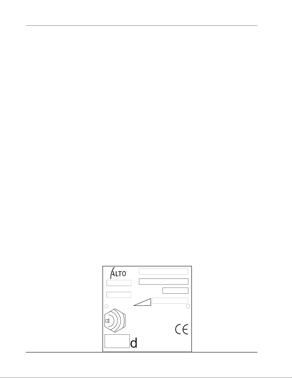
MACHINE DATA
MODEL
WEIGHT
R
IP X3
MACHINE NAME
DATE / SERIAL NUMBER
RATED POWER
MAX OPERATING SLOPE
LWA
B
1-6 American-Lincoln
ATS 46-53 Battery
Page 7
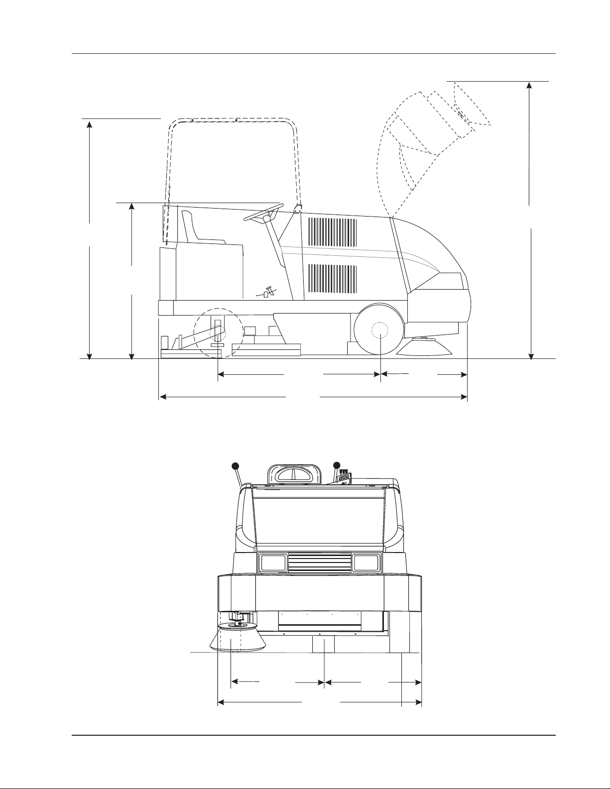
78.75“
200.025 cm
MACHINE DIMENSIONS
85.5“
217.17 cm
52“
143.5 cm
50.8“
129.03 cm
102.5“
260.35 cm
27.0“
68.60 cm
C1694d/0402
25.75“
65.41 cm
55.5“
140.97 cm
25.75“
65.41 cm
American-Lincoln 1-7
ATS 46/53 Battery
Page 8
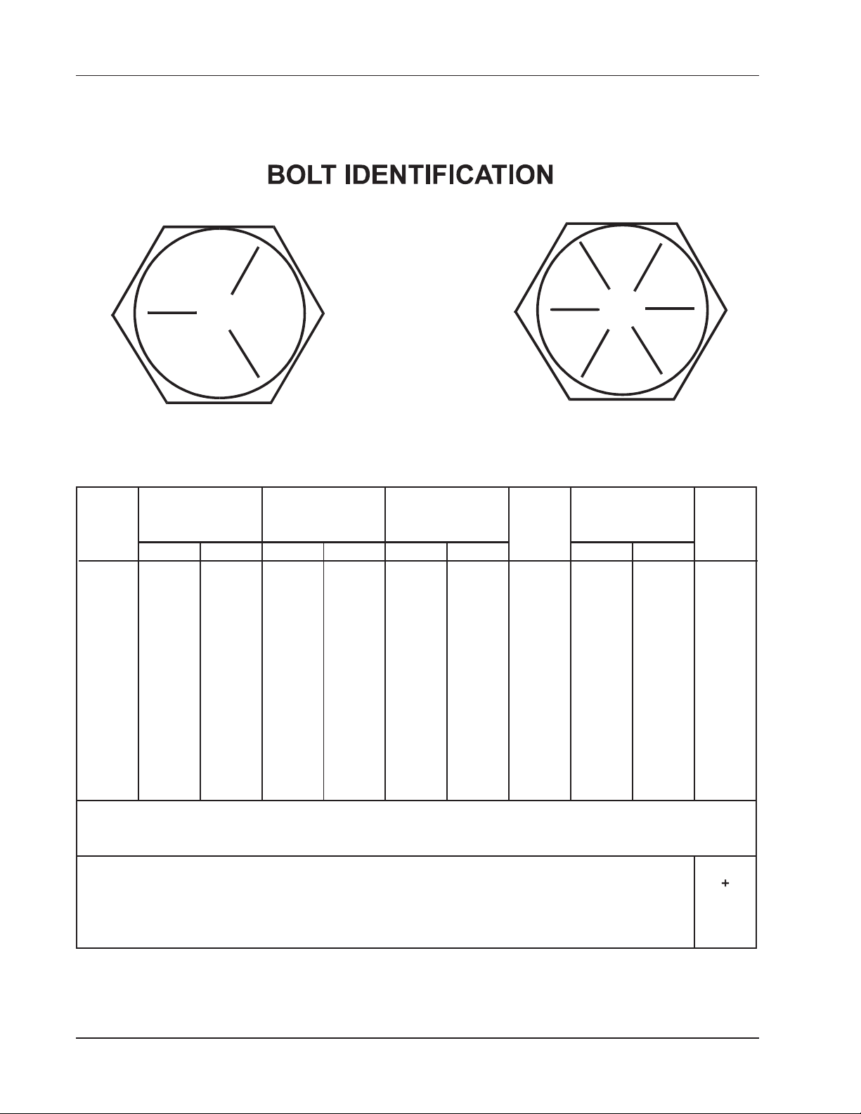
STANDARD HARDWARE & TORQUE VALUES
SAE-Grade 5
C
14
27
39
86
15
28
44
68
98
135
239
387
579
Grade
5
Plated
Grade
8
Plated
FFF
15
28
43
108
17
31
49
76
110
153
267
-
-
C
-
-
-
130
22
40
63
95
138
191
338
545
818
-
-
-
151
24
44
70
108
155
216
378
-
-
410H
Stainless
C
18
33
47
114
19
34
55
85
-
-
-
-
-
20
35
54
132
22
39
62
95
-
-
-
-
-
Screw
Size
*6
*8
*10
*1/4
5/16
3/8
7/16
1/2
9/16
5/8
3/4
7/8
1
C = Coarse Thread
F=Fine Thread
*=Tor que values for #6 through 1/4 are lb./in. All others are lb./ft.
Brass
5
9
13
32
6
10
16
-
-
-
-
-
-
SAE-Grade 8
Type
F&T
& BT
C
20
37
49
120
-
-
-
-
-
-
-
-
-
F
23
41
64
156
-
-
-
-
-
-
-
-
-
Type
B, AB
21
34
49
120
-
-
-
-
-
-
-
-
-
NOTE
Decrease the torque by 20% when using thread lubricant
The torque tolerance is ± on torque values.
C2000/9905
1-8 American-Lincoln
ATS 46-53 Battery
Page 9

HYDRAULIC TORQUE REQUIREMENTS
HYDRAULIC TORQUE REQUIREMENTS
Refer to the following chart for torque values on all hydraulic hoses and fittings.
Nominal O-Ring Face Seal End SAE O-Ring Boss End
SAE Thread Swivel Thread Str. Fitting
Dash Size Nut Size or Locknut
Size Inch Torque Inch Torque
LB-FT LB-FT
-3 **3/8-24 8-10
-4 9/16-18 10-12 7-16-20 14-16
-5 **1/2-20 18-20
-6 11/16-16 18-20 9/16-18 24-25
-8 13/16-16 32-35 3/4-16 50-60
-10 1-1446-50 7/8-14 72-80
-12 1 3/16-12 65-70 1 1/16-12 125-135
-14 1 3/16-12 65-70 1 3/16-12 160-180
-16 1 7-16-12 92-100 1 5/16-12 200-220
-20 1 11/16-12 125-140 1 5/8-12 210-280
-
24 2-12 150-165 1 7/8-12 270-360
* O-Ring face seal type end not defined for this tube size.
NOTE
Parts must be lightly oiled with hydraulic fluid.
C-2002
American-Lincoln 1-9
ATS 46/53 Battery
Page 10

DECIMAL-METRIC CONVERSION TABLE
DECIMAL-METRICCONVERSIONTABLE
Fraction Decimal Millimeter Fraction Decimal Millimeter
1 0.015625 0.3969 33 0.515625 13.0969
64 64
1 0.03125 0.7938 17 0.53125 13.4938
32 32
3 0.046875 1.1906 35 0.546875 13.8906
1 0.0625 1.5875 9 0.5625 14.2875
16 16
1 0.125 3.1750 5 0.625 15.8750
8 8
3 0.1875 4.7625 11 0.6875 17.4625
16 16
1 0.25 6.3500 3 0.75 19.0500
4 4
5 0.3125 7.9375 13 0.8125 20.6375
16 16
3 0.375 9.5250 7 0.875 22.2250
8 8
7 0.4375 11.1125 15 0.9375 23.8125
16 16
1 0.5 12.7000 1 1.0000 25.4000
2
C-2001
64 64
5 0.078125 1.9844 37 0.578125 14.6844
64 64
3 0.09375 2.3813 19 0.59375 15.0813
32 32
7 0.109375 2.7781 39 0.609375 15.4781
64 64
9 0.140625 3.5719 41 0.640625 16.2719
64 64
5 0.15625 3.9688 21 0.65625 16.6688
32 32
11 0.171875 4.3656 43 0.671875 17.0656
64 64
13 0.203125 5.1594 45 0.703125 17.8594
64 64
7 0.21875 5.5563 23 0.71875 18.2563
32 32
15 0.234375 5.9531 47 0.734375 18.6531
64 64
17 0.265625 6.7469 49 0.765625 19.4469
64 64
9 0.28125 7.1438 25 0.78125 19.8438
32 32
19 0.296875 7.5406 51 0.796875 20.2406
64 64
21 0.328125 8.3344 53 0.828125 21.0344
64 64
11 0.34375 8.7313 27 0.84375 21.4313
32 32
23 0.359375 9.1281 55 0.859375 21.8281
64 64
25 0.390625 9.9219 57 0.890625 22.6219
64 64
13 0.40625 10.3188 29 0.90625 23.0188
32 32
27 0.421875 10.7156 59 0.921875 23.4156
64 64
29 0.453125 11.5094 61 0.953125 24.2094
64 64
15 0.46875 11.9063 31 0.96875 24.6063
32 32
31 0.484375 12.3031 63 0.984375 25.0031
64 64
1-10 American-Lincoln
ATS 46-53 Battery
Page 11
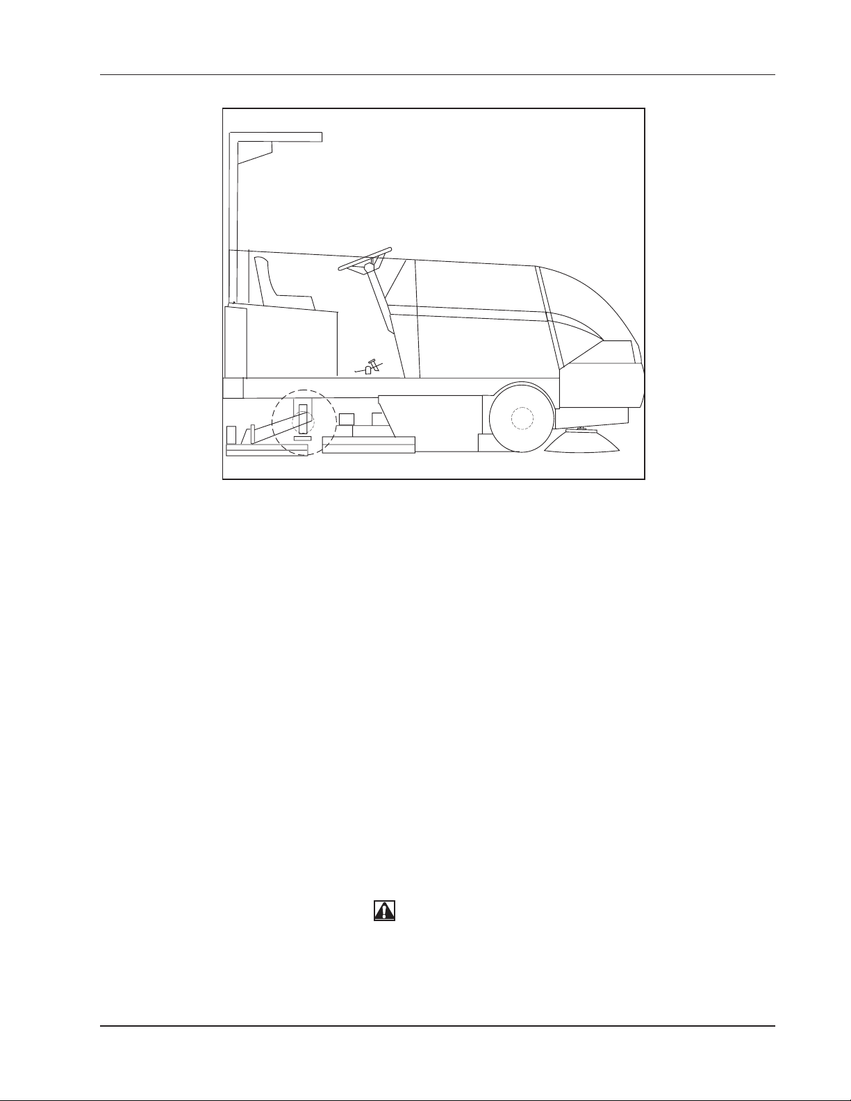
MACHINE PREPARATION
C1694c FIGURE 1
YOUR ATS 46/53 BATTERY MACHINE HAS BEEN SHIPPED COMPLETE, BUT DO NOT ATTEMPT TO
OPERATE WITHOUT FOLLOWING THESE INSTRUCTIONS.
PREPARING THE MACHINE FOR OPERATION
*Uncrate the machine and carefully remove from skid to prevent damage.
*The ATS 46/53 machines that are shipped without batteries have the (+) positive drive motor lead
disconected.
*Open the battery compartment and connect the (+) positive motor lead to the top terminal post (the wire
“P” is also attached to it). Tighten the terminal nut.
*Install the scrub brushes.
*Check the oil level in the hydraulic reservoir
*Install batteries as follows (if not included):
1. Turn the key to the “OFF” position.
2. Raise the Solution Cover to the open position.
3. Use a battery lifting device with a 2500 lbs. (1150 Kg) capacity hoist to lift the battery.
4. Using the lifting device, lower the 36 volt battery into the battery compartment directly in front of the
driver’s compartment. Orient the cables & plug them in as required.
5. Plug the polarized connector from the battery into the 36-volt plug provided.
WARNING
Hydrogen gas is formed during the charging operation and is explosive! Only charge batteries in a well-venti-
lated area with the lid open. Avoid any open flame or electrical sparks. Pulling out the charger plug with the
timer on will cause an arc and must be avoided.
American-Lincoln 1-11
ATS 46/53 Battery
Page 12

SAFETY INSTRUCTIONS
THE FOLLOWING STATEMENTS ARE USED THROUGHOUT THIS MANUAL AS INIDICATED IN THEIR
DESCRIPTIONS:
DANGER
To warn of immediate hazards which will result in severe personal injury or death.
WARNING
To warn of hazards or unsafe practices which could result in severe personal injury or death.
CAUTION
To warn of hazards or unsafe practices which could result in minor personal injury.
ATTENTION
To warn of unsafe practices which could result in extensive equipment damage.
NOTE
To give important information or to warn of unsafe practices which could result in equipment damage.
WARNING
THE FOLLOWING INFORMATION SIGNALS POTENTIALLY DANGEROUS CONDITIONS TO THE OPERATOR OR
EQUIPMENT. READ THIS MANUAL CAREFULLY. KNOW WHEN THESE CONDITIONS CAN EXIST. THEN, TAKE
NECESSARY STEPS TO TRAIN MACHINE OPERATING PERSONNEL. FOR THE SAFE OPERATION OF THIS
MACHINE, READ AND UNDERSTAND ALL WARNINGS, CAUTIONS AND NOTES.
WARNING
Machines can ignite flammable materials and vapors. Do not use with or near flammables such as gasoline,
grain dust, solvents, and thinners.
WARNING
Heavy machinery. Improper use can cause personal injury.
WARNING
Operate only when lids, doors, and access panels are securely closed.
WARNING
Use care when reversing machine in confined area.
WARNING
When servicing the machine, disconnect the batteries first to prevent possible injury.
WARNING
When working on the machine, empty hopper, remove batteries, clear area of people and obstructions, use
additional people and proper procedures when lifting the machine.
WARNING
Always empty the hopper and disconnect the battery before doing maintenance.
WARNING
You must have training in the operation of this machine before using it.
READ THE INSTRUCTION BOOK.
WARNING
Do not operate this machine unless it is completely assembled.
WARNING
Do not use this machine as a step or furniture.
1-12 American-Lincoln
ATS 46-53 Battery
Page 13

SAFETY INSTRUCTIONS
WARNING
Stop and leave this machine on a level surface. When you stop the machine, put the power switch in the “OFF”
position and engage the Wheel Lock.
WARNING
To prevent injury and damage to the machine, do not lift the machine
or move it to an edge of a stair or loading dock.
WARNING
Lead acid batteries generate gases, which can cause an explosion. Keep sparks and flames away from batteries.
NO SMOKING. Charge batteries only in areas with good ventilation.
WARNING
Always wear eye protection and protective clothing when working near batteries. Remove all jewelry. Do not put
tools or other metal objects across the battery terminals or across the tops of batteries.
WARNING
Only authorized personnel should do maintenance and repairs. Tighten all fasteners. Maintain adjustments
according to the specifications given in the service manual for the machine. Keep the electrical parts of the
machine dry. For storage, keep the machine in a building.
WARNING
Make sure all labels, decals, warnings, cautions and instructions are fastened to the machine. Purchase new
labels and decals from American-Lincoln.
WARNING
The operator must exhibit extreme caution when negotiating, turning, and traveling across grades or ramps.
Start, stop, change direction, travel and brake smoothly. Slow down when turning.
WARNING
Avoid uneven surfaces and loose materials. Watch for obstructions, especially overhead.
WARNING
Operate only from the designated operator’s position. Stay inside the body of the machine. Keep hands and feet
on the designated controls. Always operate in well-lighted areas.
WARNING
Do not carry passengers on the machine. Set the Wheel Lock when leaving the machine. Chock (block) the
wheels if the machine is parked on a grade (ramp), or is being prepared for maintenance.
WARNING
Never leave the operator’s compartment when the machine is running.
WARNING
Report damage or faulty operation immediately. Do not operate the machine until repairs have been completed.
Only authorized personnel should do maintenance and repairs.
WARNING
To maintain the stability of this machine in normal operation, the overhead guard, counterweights, rear bumper
guard, or any similar equipment installed by the manufacturer, as original equipment should never be removed.
If it becomes necessary to remove such equipment for repair or maintenance, this equipment must be reinstalled
before the machine is placed back into operation.
WARNING
Electrical hazard. Shocks can cause serious personal injury. Unplug the battery before cleaning or servicing. To
avoid possible injury or property damage, read the Operator’s Manual before servicing the machine. Authorized
personnel should do maintenance and repairs.
American-Lincoln 1-13
ATS 46/53 Battery
Page 14

SAFETY INSTRUCTIONS
WARNING
Disconnecting the battery connector with the key switch in the “I” position will cause sparks that could ignite
explosive hydrogen gas generated by the batteries. To prevent serious injury or possible property damage, turn
Key Switch to “O” position before disconnecting the battery cable from the machine for charging or service.
FOR SAFETY, OBSERVE THE FOLLOWING WARNINGS. FAILURE TO COMPLY MAY CREATE A SERIOUS RISK OF INJURY TO YOU AND OTHERS. THIS MACHINE SHOULD NOT BE USED IN HAZARDOUS
LOCATIONS INCLUDING AREAS OF VOLATILE DUST OR VAPOR CONCENTRATIONS.
Operators must be trained and qualified to operate this machine. They must also understand the
operator’s manual before starting.
Use caution when mounting or dismounting the machine, particularly on wet/slippery surfaces.
Do not dump the hopper over an open pit or dock. Do not dump the hopper when positioned on a
grade (ramp). The machine must be level (horizontal).
1-14 American-Lincoln
ATS 46-53 Battery
Page 15
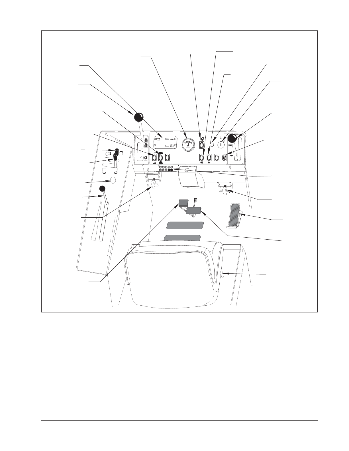
OPERATION OF CONTROLS AND GAUGES
CIRCUTBREAKERS
COMBINATION
BATTERY CONDITION
& HOUR METER
LIGHT
SWITCH
WORK
LIGHT
(Option)
MAIN
BROOM
LEVER
HOPPER
LEVER
HORN
BUTTON
SCRUB
DECK
SWITCH
SQUEEGEE
SWITCH
MAIN
BROOM
ADJUSTMENT
PARKING
BRAKE
SOLUTION
CONTROL
LEVER
HOPPER
DOOR
LEVER
WARNING
BANK
FWD/REV
SWITCH
FILTER
SHAKER
SWITCH
WET SWEEP
BYPASS
(Option)
SIDE
BROOM
LEVER
KEY
SWITCH
SIDE
BROOM
ADJUSTMENT
CIRCUIT
BREAKERS
BRAKE
PEDAL
SEAT
ADJUSTMENT
FOOT
PEDAL
-
+
P5034b-1batt FIGURE 2
LIGHT SWITCH (See Figure 2)
The light switch is located on the instrument panel to the right of the battery condition/hour meter. It will work
various light options available for this machine, such as:
* HEAD LIGHTS
* TAIL LIGHTS
* INSTRUMENT LIGHTS
HORN BUTTON (See Figure 2)
The horn button is located on the left side control panel. Push the button to sound the horn. The horn button is
always active.
American-Lincoln 1-15
ATS 46/53 Battery
Page 16

OPERATION OF CONTROLS AND GAUGES
KEY
SWITCH
C1631A-batt FIGURE 3
FWD/REV
KEY SWITCH (See Figure 3)
The keyed ignition switch is located on the instrument
panel to the left of the side broom lever. The key switch is
a two-position switch that controls power to the machine
systems and accessories. The “OFF” position (O position)
will shut off the machine. The IGN/ON position (I position)
provides power to the machine and all its systems and
accessories.
NOTE
The operator should never leave the machine
unattended while it is on.
FORWARD/REVERSE SWITCH (See Figure 3)
A two-position switch controls the machine’s direction and
is located on the righthand side of the instrument panel
directly below the key switch. Pushing the upper portion of
the switch will provide forward motion when the foot pedal
is pressed. Pushing the bottom portion of the switch will
make the machine move in reverse when the foot pedal is
pressed.
NOTE
The machine will not move if:
The operator is not seated properly in the operator’s
compartment due to the Seat Switch Interlock safety
feature; or if the foot pedal is depressed or depressed too
quickly after turning the key switch on as a result of the High
Pedal Disable safety feature. (See “MillipaK SEM Controller”)
HOUR
METER
C1633-batt FIGURE 4
SEAT
POSITION
ADJUSTMENT
LEVER
TO
LOCK
BATTERY
CONDITION
METER
TO ADJUST
COMBINATION BATTERY CONDITION & HOUR METER
(See Figure 4)
The combination battery condition and hour meter is
located on the instrument panel next to the warning bank.
The meter is activated when the key switch is placed in the
ignition position. The hour meter indicates the actual “run”
time of the machine and can be used to determine machine maintenance intervals.
The battery condition meter indicates the charge level of
the batteries. The batteries are sufficiently charged if all
the amber LEDs are illuminated during the machine’s
operation.
If the LED on the far left displays red while using the
machine, the low voltage lockout safety feature will shut
down the scrub deck’s operation. The batteries must now
be fully charged in order to reset the low voltage lockout
and continue the cleaning operation.
SEAT POSITION ADJUSTMENT (See Figure 5)
The seat position adjustment lever is located on the right
side of the seat base. The lever is spring loaded to the
“LOCK” position.
C-0508a
C0508A-2 FIGURE 5
1-16 American-Lincoln
To adjust the seat, push “FORWARD” on the lever and
move the seat to the desired position. Then release the
lever to “LOCK” the seat into place.
ATS 46-53 Battery
Page 17

FILTER
SHAKER
C1640-2batt FIGURE 6
OPERATION OF CONTROLS AND GAUGES
FILTER SHAKER SWITCH (See Figure 6)
The filter shaker switch is located on the instrument panel
below the ignition switch. This is a momentary switch
that will activate the filter shaker motors for 20 to 30
seconds to clear the dust control filter. The Impeller fan
will stop when the filter shaker has been activated. The
filter shaker will only operate with the hopper in the
“DOWN” position.
Use the filter shaker to clear the filter when the dust
control light comes on (warning bank) and just before
dumping the hopper.
MillipaK SEM CONTROLLER (See Figure 7)
The controller is located in the seat compartment and
includes a number of features designed to help the user
track down operational faults, wiring faults or internal
controller faults, including a flashing indicator light.
The Flash Codes are:
CONTROLLER
PUMP MOTOR PUMP
FIGURE 7
HOPPER
SAFETY ARM
MODELNO. SERIALNO.
C1700
C1700 FIGURE 8
TO
ENGAGE
ON No fault, normal condition
OFF Internal controller fault
1 flash Program Error
2 flashes High Pedal Disable
3 flashes MOSFET Short Circuit
4 flashes Contactor fault or Motor Open Circuit
5 flashes Not used
6 flashes Accelerator wire off fault
7 flashes Low or High battery voltage
8 flashes Over temperature or timed cutback
HYDRAULIC PUMP (See Figure 7)
The pump is located in the seat compartment and is
powered by a 45 amp circuit breaker (on the power panel)
and a contact linked with the key switch. It functions at
1450 PSI and features 100 bar relief.
HOPPER SAFETY LOCK ARM (See Figure 8)
The hopper safety arm is located near the right front wheel
well. The safety arm will prevent the hopper from dropping
unexpectedly during service/maintenance.
TO ENGAGE THE SAFETY ARM:
1. Empty hopper
2. Set the parking brake.
3. Raise the hopper.
4. Lift safety arm to engage the slot on the hopper
frame.
5. When work has been completed, return the
safey arm to the stowed position.
WARNING
When the hopper is raised the safety arm must be engaged
before ANY work is done under the hopper.
American-Lincoln 1-17
ATS 46/53 Battery
Page 18

OPERATION OF CONTROLS AND GAUGES
A
SIDE BROOM LEVER (See Figure 9)
SIDE
BROOM
The Side Broom Lever is located to the right of the instrument console. The handle pulled back and turned to the
left, will raise the side broom and lock it into position.
LEVER
To raise the side broom pull the lever back into the “UP”
position.
SIDE
BROOM
To lower the side broom, move the lever out of the “UP”
position and move it forward to the “DOWN” position.
ADJUSTMENT
IF THE MAIN BROOM IS ENGAGED, THE SIDE BROOM WILL
SIDE BROOM ADJUSTMENT (See figure 9)
The side broom lever has an adjustment for changing the
sweep height to compensate for broom wear. The side
broom adjustment is located under the right side of the
instrument panel.
NOTE
AUTOMATICALLY ENGAGE WHEN LOWERED.
C1641batt FIGURE 9
MAIN
BROOM
LEVER
MAIN
BROOM
DJUSTMENT
C1642-1batt FIGURE 10
MAIN BROOM LEVER (See figure 10)
The main broom lever is located on the left side of the
instrument panel. The main broom lever has three positions and controls the main broom sweep height.
To lower the main broom, grasp the lever and move it to
the left out of the “UP” position, and place it in the
“SWEEP” or “FLOAT” position.
The “SWEEP” position is used for normal sweeping and
should be used under most sweeping conditions (approximately 2” broom pattern).
The “FLOAT” position is used for sweeping very uneven
surfaces only. Using the float position will cause premature
wear on the main broom if used under normal operating
conditions for extended periods of time (approximately 4”
broom pattern).
CIRCUTBREAKERS
NOTE
The Main Broom will automatically engage when lowered to
the sweep position or the float position. The hopper must be
completely closed.
MAIN BROOM ADJUSTMENT (See Figure 10)
The main broom lever has an adjustment for changing the
sweep height to compensate for broom wear. The main
broom adjustment is located under the left side of the
instrument panel.
1-18 American-Lincoln
ATS 46-53 Battery
Page 19

DUST
CONTROL
SWITCH
(Wet Sweep
Bypass)
C1640-1batt FIGURE 11
SCRUB DECK
SWITCH
OPERATION OF CONTROLS AND GAUGES
DUST CONTROL SWITCH (See Figure 11)
The Dust Control Switch is a two position switch located on
the instrument panel next to the filter shaker switch. The
switch controls the vacuum fan in the dust control system.
To turn on the dust control system for “NORMAL” sweeping,
press on the top portion of the switch. To turn off the dust
control system for sweeping in wet conditions, press the
lower portion of the switch. This will prevent the filter from
being damaged by water pickup while sweeping.
SCRUB DECK SWITCH (See Figure 12)
The brushes switch is located on the console to the left of
the steering wheel in the “SCRUBBING” section. This switch
in the position marked “LOWER” will lower the scrub deck
and activate the three scrub brushes. This switch in the
“RAISE” position will stop the brushes from rotating and
raise the scrub deck.
CIRCUTBREAKERS
C1642A-batt FIGURE 12
SQUEEGEE
SWITCH
CIRCUTBREAKERS
NOTE
Lowering the scrub deck will not start the brushes rotating.
The machine must be moving to engage the scrub brushes. If
the machine stops moving for 2 seconds or more, the
brushes will automatically stop rotating until the machine
starts moving again.
SQUEEGEE SWITCH (See Figure 13)
The squeegee blade switch is located on the console to the
left of the steering wheel in the “SCRUBBING” section. This
switch in the position marked “LOWER” will lower the
squeegee and activate the squeegee vacuum. This switch in
the “RAISE” position will stop the squeegee vacuum and
raise the squeegee. If the machine is put in reverse, a
switch is automatically activated to raise the squeegee if in
the lowered position as well as stop the vacuum.
The switch has a center position which will raise the squeegee but allows the vacuum to continue running, retrieving the
water left in the squeegee recovery hose. This prevents
water from dripping on the floor with the squeegee “UP.”
C1642B -batt FIGURE 13
American-Lincoln 1-19
ATS 46/53 Battery
Page 20

OPERATION OF CONTROLS AND GAUGES
SOLUTION
CONTROL
C1716batt FIGURE 14
CIRCUTBREAKERS
SOLUTION CONTROL (See Figure 14)
To apply solution to the scrub brushes, pull the solution control lever back until the desired setting is reached.
The solution rate is continuously variable from off to approximately 1-3/4 GPM at low and 3 GPM at high. To
stop application of solution push forward on the lever until it stops at the “off” position. The solution warning light
will illuminate when the solution tank is low, marking the end of the scrubbing cycle.
NOTE
For best results, discontinue application of solution 10 feet before stopping or making a 90° or 180° turn.
NON-RECYCLING OR STANDARD SCRUBBING SYSTEM
1. Make sure the solution control lever is in the “off” (FORWARD) position.
2. Open the solution tank cover (Vacuum Assembly)
3. Fill the tank with 70 gallons of water and the correct mixture of American-Lincoln #100 Industrial
Cleaner for the job on hand.
4. Close the solution tank cover (Vacuum Assembly).
RECYCLING OR ESP & AUTOFIL SYSTEM
1. Make sure the solution control lever is in the “off” position.
2. Connect hose to autofil coupling.
3. Turn the key switch to the “ACC” position.
4. Turn on the water hose valve.
5. Fill the detergent tank with American-Lincoln #100 Industrial Cleaner.
6. The system will fill the solution and recovery tank to proper levels and shut off the water flow.
TO DISCONNECT WATER HOSE
1. Leave ignition switch in the “on” position
2. Turn the water off at the source
3. “Tip” the float switch on the solution tank to depressurize the water hose before disconnecting
WARNING
To prevent oversudsing and machine damage, use only AMERICAN-LINCOLN Industrial Cleaner Solution #100.
DO NOT put gasoline, combustible or flammable material in the solution, detergent, or recovery tanks.
1-20 American-Lincoln
ATS 46-53 Battery
Page 21

OPERATION OF CONTROLS AND GAUGES
WARNING
BANK
CHARGING SYSTEM
LIGHT
RECOVERY
HIGH
LIGHT
CLOGGED
FILTER LIGHT
SOLUTION
LOW LIGHT
HOPPER
TEMP
LIGHT
C1636batt FIGURE 15
WARNING BANK (See Figure 15)
The Warning Bank is located on the instrument panel and provides the operator with fault/status indicators for
engine and sweeper systems. The operator should monitor the indicators while sweeping. It is very important
that the operator be familiar with the meaning of each indicator.
CHARGING SYSTEM LIGHT
The charging system light illuminates to indicate a charging system fault. When this occurs the
machines charging system is not working properly, have the machine serviced by a qualified
service technician.
CLOGGED FILTER LIGHT (Option)
The clogged filter light illuminates to indicate that the dust control filter is clogged. When this
occurs, stop the machine and use the filter shaker to clear the dirt and debris from the filter. After
using the filter shaker, continue sweeping.
HOPPER TEMPERATURE LIGHT (Option)
When the temperature of the air moving through the hopper dust control system exceeds 140° F,
an automatic protection feature shuts down the dust control fan and illuminates the hopper temperature light. When this occurs, shut down the machine and carefully investigate for a possible fire
in the hopper, then manually reset the switch.
SOLUTION LOW LIGHT
The solution low warning light will illuminate when the solution tank is empty, indicating the end of
the scrubbing cycle.
RECOVERY HIGH LIGHT
The recovery high warning light will illuminate approximately 5 minutes before the recovery tank is
full, giving ample time to complete the scrubbing cycle, before the mechanical float shuts off the
vacuum to the recovery tank.
American-Lincoln 1-21
ATS 46/53 Battery
Page 22

OPERATION OF CONTROLS AND GAUGES
PARKING
BRAKE
BRAKE
FOOT PEDAL
C1789batt FIGURE 18
FOOT PEDAL (ACCELERATOR)
The foot pedal, or accelerator, is located on the right side of the operator compartment floor. The foot pedal
provides speed control only. To set the machine in motion, push the forward/reverse switch up or down (see
figure 3), then push down on the foot pedal. Smoothly releasing the pedal will help slow the machine before
breaking.
BRAKE PEDAL
The foot brake is located on the floor of the operator’s compartment to the left of the accelerator. To stop,
remove foot from accelerator and apply pressure to the brake pedal.
PARKING BRAKE
The parking brake is located just above and slightly left ofthe foot brake. When engaged, the parking brake
“locks” the foot brake in the down position.
To engage the parking brake, press down on the parking brake pedal.
To release the parking brake, press down on the regular brake pedal.
1-22 American-Lincoln
ATS 46-53 Battery
Page 23

HOPPER
LEVER
HOPPER
DOOR
LEVER
OPERATION OF CONTROLS AND GAUGES
C1717
C1717 FIGURE 19
NOTE
The main broom, side broom, dust control and filter shaker turn off automatically when the hopper is dumping and/
or the dump door is in a closed position. SEE HOPPER LIFT and HOPPER DUMP DOOR.
HOPPER LIFT LEVER - (See Figure 19)
The hopper lift lever is located to the left of the steering wheel on the left side of the driver’s compartment. This
lever, which is marked “HOPPER”, raises and lowers the debris hopper to ease unloading.
WARNING
The hopper may drop unexpectedly and cause injury, always engage the safety arm before working under the
hopper.
HOPPER DUMP DOOR LEVER - (See Figure 19)
The hopper dump door lever is located to the left of the steering wheel on the left of the driver compartment.
This lever opens and closes the hopper door. This lever is located below the hopper lift door and is marked
“DUMP DOOR”.
NOTE
A switch triggered by the hopper and dump door’s position control the sweeping functions, main broom, side
broom, dust control, and filter shaker. The hopper must be down and the dump door open to allow these to
operate.
American-Lincoln 1-23
ATS 46/53 Battery
Page 24

OPERATION OF CONTROLS AND GAUGES
TURN SIGNAL
SWITCH
TO TURN
ON 4-WAY
FLASHER
LIGHTS
TO SIGNAL
RIGHT TURN
TO SIGNAL
LEFT TURN
4-WAY F LASHER
SWITCH
+
-
C1702batt FIGURE 20
TURN SIGNAL - 4-Way (Option) (See Figure 20)
The turn signal option is located on the steering column and works as automotive turn signals work, forward on
the lever for right and back on the lever for left. The 4-way flasher will activate when the turn signal lever is pulled
out.
BACK-UP ALARM SWITCH (Option) (See Figure 20)
The back-up alarm is activated by a switch that is located under the lower section of the accelerator pedal and
the forward/reverse switch. The alarm makes a loud audible noise when the machine is being driven in reverse.
1-24 American-Lincoln
ATS 46-53 Battery
Page 25

OPERATION OF CONTROLS AND GAUGES
TURN LATCH
TORELEASE
FILTER
PANEL
C-1719
C1719 FIGURE 21
RESET
BUTTON
PUSH
RESET
HOPPER
TEMP
SENSOR
TO
LIFT
FRAME TO
REMOVE
FILTER
FILTER
PANEL
LATCH
FILTER PANEL LATCH (See Figure 21)
The filter panel is located in the hopper filter compartment
and will need to be removed periodically for cleaning or
replacement. Removal of the filter panel requires no tools.
The hopper cover must be opened to gain access to the
filter compartment. The panel filter is held in place by a
hinged frame and latch.
To remove the panel filter, turn the knob counterclockwise
and lift the hinged frame.
The panel filter can now be lifted out and cleaned or replaced (see Filter Cleaning instructions in this manual).
To install the replacement panel filter, lower the frame and
turn the knob clockwise to lock the filter in place.
HOPPER TEMP SENSOR (Option) (See Figure 22)
The temp sensor switch monitors the hopper air temperature near the vac fan. When the temperature of the air
moving through the hopper exceeds 140°F, the switch is
tripped. It turns off the dust control fan and illuminates the
hopper temp light on the warning bank.
The hopper temp sensor can be reset thermal switch which
is located in the hopper filter compartment near the
vacuum fan intake.
C1718/9705
C1718 FIGURE 22
PUSH
LIFT
AND
TURN
C1722-9706
C1722 FIGURE 23
When the hopper temp light illuminates, carefully investigate for a possible fire in the hopper.
To reset the temp sensor, press the reset button.
FRONT COVER LATCH (See Figure 23)
The front cover encloses the power source. The cover can
be lifted to allow easy access for service and inspection.
WARNING
Operate Only When Lids, Doors, And Access Panels Are
Securely Closed.
To open the cover, lift the cover latch lever up and turn the
latch ¼ turn. Lift the cover open.
NOTE
The overhead guard option has a safety latch for storing
open cover.
After closing the cover, check it to be certain the latch has
fully engaged and is latched.
NOTE
Side covers can be removed for service.
American-Lincoln 1-25
ATS 46/53 Battery
Page 26

OPERATION OF CONTROLS AND GAUGES
HYDRAULICRESERVOIR
LEVELSIGHT GAUGE
C1730 FIGURE 24
MAINBROOM
COMPARTMENT
LATCH
C0729A/9707
PULL UP
TOOPEN
HYDRAULIC RESERVOIR LEVEL SIGHT GAUGE
(See Figure 24)
The sight gauge is located on the inside of the hydraulic
reservoir in the engine compartment. The sight gauge is
used to indicate the level of fluid in the reservoir. The fluid
level must be visible in the sight gauge when the hopper is
in the down position.
MAIN BROOM COMPARTMENT DOORS (See Figure 25)
The main broom compartment doors are located behind the
front tires on both sides of the machine. The doors provide
access to the main broom for service or inspection.
WARNING
Operate Only When Lids, Doors, And Access Panels Are
Securely Closed.
Open the right side door to remove or replace the main
broom. The right side door is an integral part of the main
broom drive system and must be closed for operation.
Open the left side broom door for inspection. Check the
drive hub for banding and shrink-wrap which have a
tendency to get tangled in the broom driver. To open the
main broom door, reach inside the hole in the door and lift
up on the latch handle. The door latch will automatically
engage when the door is closed.
NOTE
Side squeegees mount on doors and the scrub deck must
be lowered to slide the doors and squeegees into place.
C0729A FIGURE 25
-
C1699a-batt FIGURE 26
NOTE
For proper function of side squeegees, side squeegees must
be positioned so the lift strap is above the scrub deck lift
brackets. Damage to the side squeegees could occur if not
in the correct position.
SEAT COMPARTMENT COVER & PROP LATCH
(See Figure 26)
The seat compartment cover opens to allow easy access to
various components that will need to be inspected or
serviced periodically. The cover opens forward and has a
safety latch to hold the cover in the open position.
On battery-powered machines, the compartment below the
seat contains the hydraulic pump motor and reservoir.
The seat compartment latch is located under the seat
compartment cover and is used to hold the cover open.
To hold the seat compartment cover open, lift the cover and
rotate the latch.
1-26 American-Lincoln
ATS 46-53 Battery
Page 27

OPERATION OF CONTROLS AND GAUGES
HOPPER DOOR LEVER (See Figure 27)
The hopper door lever is located on the operator’s compartment and is used to close and open the hopper dump
door. The lever is a two position hydraulic valve that is
spring loaded to the center position which “HOLDS” the
hopper door in position.
HOPPER
DOOR
LEVER
(Variable Dump
Hopper Only)
C1717A FIGURE 27
HOPPER
LEVER
To open the hopper dump door for sweeping or dumping,
push the lever to the “OPEN” direction.
To close the hopper dump door for dumping or transporting, push the lever fully back in the “CLOSE” direction,
and hold for 3 seconds or until you hear the door close.
HOPPER LIFT LEVER (See Figure 28)
The hopper lift lever is located on the operator’s compartment console. The lever is a two position hydraulic valve
that controls the operation of the hopper lift system. The
lever is spring loaded to the center position which stops
hopper movement and “HOLDS” the hopper at the present
position.
To raise the hopper for dumping, move the lever to the
“RAISE” position and hold until the hopper reaches the
desired height, then release.
WARNING
The hopper may drop unexpectedly and cause injury,
always engage the safety arm before working under the
hopper.
C1717B FIGURE 28
To lower the hopper after dumping, move the lever to the
“LOWER” position until the hopper is fully lowered and
seated in the machine, then release.
LIFT TOOPEN
HOPPER FILTER COVER
(See Figure 29)
The hopper filter cover is actually the front cover or “hood”
of the machine. It opens forward by releasing latches to
access the filter compartment for service/inspection of the
dust control filter and optional hopper temp sensor.
Inspect gaskets daily. Replace any gaskets that show
signs of deterioration. Failure to maintain the gaskets in
serviceable condition will degrade dust control at the floor
and will result in less than optimal sweeping performance.
C1725A-batt FIGURE 29
American-Lincoln 1-27
ATS 46/53 Battery
Page 28

ESP SYSTEM OPERATING INSTRUCTIONS
ESP SYSTEM
INSTRUMENT PANEL
(OPTION)
ON
OFF
RECYCLING SYSTEM
ON/OFF SWITCH
C1713/9705
C1713 FIGURE 30
THE ESP RECYCLING CONTROL PANEL (See Figure 30)
THE ESP RECYCLING SYSTEM ON/OFF SWITCH
This switch turns the ESP recycling system on and off.
SOLUTION LEVEL
WARNING LIGHT
DETERGENT
FLOW KNOB
DETERGENT LOW
WARNING LIGHT
NOTE
The solution control lever must be on “FULL” for ESP operation.
SOLUTION LEVEL WARNING LIGHT
The solution level warning light will go out when the solution tank is empty. Some solution will remain in the
recovery tank at the end.
DETERGENT LOW WARNING LIGHT
The detergent light will illuminate when the detergent tank is low, warning the operator to add detergent.
DETERGENT FLOW KNOB
This rotary knob controls the detergent flow into the scrubbing solution. The operator may choose from any
detergent setting, for light to heavy cleaning applications. The detergent light will illuminate when the detergent
tank is low, warning the operator to add detergent.
1-28 American-Lincoln
ATS 46-53 Battery
Page 29

ESP SYSTEM OPERATING INSTRUCTIONS
NON - RECYCLING RECYCLING
DETERGENT
TANK
SOLUTION
TANK
SOLUTION
TANK
RECOVERY
TANK
C1728 FIGURE 32
THE SCRUBBING SYSTEM - HOW IT WORKS
There are two scrubbing systems available for the ATS 46/53 machine, the non-recycling or standard scrubbing
system and the recycling or ESP scrubbing system.
THE NON-RECYCLING OR STANDARD SCRUBBING SYSTEM - HOW IT WORKS
During the scrubbing process, detergent solution water from the solution tank is fed to the solution line. There
it is fed to the floor where three disc scrubbing brushes work to dislodge soil.
RECOVERY
TANK
After scrubbing, the dirty solution is vacuumed from the floor and discharged into the containment chamber in
the forward portion of the recovery tank, where a system of baffles helps to clarify the solution.
Sensors in each tank will indicate, by lights on the control panel, when the water in the solution tank is too low
or when the water in the recovery tank is too high.
American-Lincoln 1-29
ATS 46/53 Battery
Page 30

ESP SYSTEM OPERATING INSTRUCTIONS
THE RECOVERY OR ESP AND AUTOFIL SYSTEM - HOW IT WORKS
During the scrubbing process, filtered water from the solution tank is fed to the solution line, where it combines
with detergent from the metering pump. This mixture is then fed to the floor where three disc scrubbing brushes
work to dislodge soil.
After scrubbing, the dirty solution is vacuumed from the floor and discharged into the recovery tank. At intervals, a float switch activates the recycling pump, which sends filtered solution from the recovery tank to the
solution tank. Detergent is added continuously to solution water from the flow valve.
The autofil system distributes water from the supply hose into the recovery and solution tanks. Then a solenoid
valve is closed when the proper level in the solution tank is reached.
NOTE
Both tanks must be drained and cleaned before filling.
Tuck solution tank drain hose behind bumper during operation hose
ORIFICE
DETERGENT
TANK
DETERGENT
PUMP
P4759a
CHECK
VALVE
SOLUTION
TANK
SOLUTION
PUMP
FILTER
FLOW VALVE
SEPARATOR
SCRUB
BRUSH
FLOOR CONTACT
FILTER
AUTOFIL
VALVE
FILL COUPLING
SQUEEGEE
RECOVERY
TANK
P4759A FIGURE 33
1-30 American-Lincoln
ATS 46-53 Battery
Page 31

OPERATING INSTRUCTIONS
SWEEPING AND DUST CONTROL SYSTEMS-HOW THEY WORK
ATS 46/53 machines are equipped with a sweeping and dust control system. (See Figure 34)
DUST CONTROL
C1731 FIGURE 34
BEFORE STARTING THE MACHINE
1. Set parking brake.
2. Make sure all controls are in the “OFF” position.
3. Be sure the directional control switch is in the center position.
4. Ensure the batteries have been fully charged and serviced (see battery service instructions).
NOTE
Before starting the machine, perform the pre-start checklist.
PRE-START CHECKLIST
1. Check hydraulic fluid level.
2. Check all systems for leaks.
3. Check brakes and controls for proper operation.
4. Check broom patterns.
5. Check to ensure that all covers, panels and access doors are securely closed.
STARTING BATTERY MACHINES
Starting the battery powered models is accomplished by turning the key switch to the “I” (on) position. It is
important to note that the batteries should be fully charged and serviced prior to using the machine.
American-Lincoln 1-31
ATS 46/53 Battery
Page 32

OPERATING INSTRUCTIONS
EMPTYING THE DEBRIS HOPPER
1. Remove foot from accelerator and stop the machine.
2. Engage the parking brake.
3. Move the hopper dump door lever to the “CLOSE” position until the door is closed.
4. Move the hopper lift lever to the “RAISE” position until the hopper reaches the desired height.
5. Disengage the parking brake.
6. Drive forward slowly with hopper raised to clear the refuse container before opening hopper dump door.
7. Stop machine and engage the parking brake.
8. Push the hopper dump door lever forward to the “OPEN” position. This will allow debris in the hopper to
fall out into the refuse container.
9. Move the hopper dump door lever to the “CLOSE” position until the door is closed.
10. Release the parking brake.
11. Drive slowly in reverse to clear the refuse container.
12. Stop machine and engage the parking brake.
13. Move the hopper lift lever forward to the “LOWER” position and hold until the hopper is closed.
14. Move the hopper dump door lever to the “OPEN” position until the dump door opens.
WARNING
Do not turn off the machine with the hopper in the lifted position.
NOTE
After stopping the machine, perform these post-operation checks.
POST-OPERATION CHECKLIST
1. Clean the debris hopper.
2. Check sweeping brooms for wear or damage.
3. Check all flaps for wear, damage and adjustment.
4. Check all systems for leaks.
5. Charge and service motive power batteries (see battery charging instructions).
6. Check squeegees for damage.
BATTERY CHARGING INSTRUCTIONS
Charge the batteries at the end of each day or when the battery condition meter indicates low battery voltage.
The batteries need to be charged when the needle stays in the “red” zone while the machine is being operated.
When charging the batteries, only use the quick disconnect provided to ensure correct polarity. Follow the
instructions below.
Check the liquid level in the batteries at least once a week and add water when low. Use only distilled water.
Fill the batteries after charging them to prevent electrolyte from spilling over onto the tops of the batteries
during the charging process.
WARNING
The use of an extension cord with the charger should be avoided. Risk of fire and electrical shock is possible if
the wrong type or size extension cord is used. Locate all cords so they cannot be stepped on, tripped over, or
otherwise subjected to damage or stress.
STORAGE FOR BATTERY-POWERED MACHINES
When batteries are not in use, they will discharge much sooner in cooler temperatures than in warm temperatures. Recharging and storing is more efficient at room temperature.
Do not discharge the batteries excessively (do not go below 80%). Excessive discharge can cause polarity
reversal of the individual cells in the battery. This will lead to complete failure of the batteries.
Use a hydrometer to monitor the specific gravity of the individual cells in the batteries. When checking the
specific gravity of the batteries, you should not see a large difference between the individual cells. The batteries
may need to be replaced if the battery shows a significant difference of specific gravity between the cells.
1-32 American-Lincoln
ATS 46-53 Battery
Page 33

HELPFUL HINTS FOR CLEANING OPERATION
P4134/0001
SIDE AISLES
MAIN AISLE
SIDE AISLES
P4134 FIGURE 35
WARNING
Do not turn the steering wheel sharply when the machine is in motion. The machine is very responsive to
movement of the steering wheel. Do not make sudden turns. Scrub in straight paths. Do not bump posts. Do
not scrape the sides of the machine.
When the machine is in motion, do not push the foot pedal all the way down. This will put a strain on drive
system.
1. Plan your sweeping and scrubbing in advance. Try to arrange long runs with minimum stopping and
starting. Sweep debris from narrow aisles out into main aisles ahead of time. Do an entire floor or section
at one time.
2. Pick up oversize debris before sweeping.
3. Allow a few inches of overlap of sweep and scrub paths. This will eliminate leaving dirty patches.
4. Do not turn steering wheel too sharply when the machine is in motion. The machine is very responsive to
movement of the steering wheel, so avoid sudden turns.
5. Try to follow as straight a path as possible. Avoid bumping into posts or scraping the sides of the machine.
6. When placing the machine in motion, avoid slamming the directional control pedal all the way forward
quickly. This is equivalent to starting in “High” and puts needless strain on the engine and drive system.
7. Always allow the machine to warm up before operating in cold temperatures.
8. Periodically turn the sweeping broom end-over-end to prevent the bristles from “setting” in one direction.
NOTE
Replace the sweeping broom when the bristles are worn to 3 inch (8cm) length. Replace disc brushes when
bristles are reduced to ½ inch (1.3 cm) in length. Replace squeegee rubbers when all usable edges have become
American-Lincoln 1-33
ATS 46/53 Battery
rounded with wear.
Page 34

SERVICE CHART
SERVICE CHART
Check items for proper operation. If service is required, please contact an authorized American-Lincoln dealer.
For best performance, replace worn parts with genuine American-Lincoln parts.
EVERY 8 HOURS or DAILY operation check and clean/adjust if necessary:
1. Inspect panel filters for damage and clean them.
2. Check hydraulic fluid level.
3. Check all flaps for wear or damage.
4. Check brooms for wear or damage, adjust as required.
5. Check panel filters (clean side) for leakage.
6. Check brake pedal and parking brake.
7. Check hydraulic oil filter.
8. Check battery electrolyte level (unless maintenance-free battery).
9. Check all fluid system components for leaks.
50 HOUR (WEEKLY) MAINTENANCE CHECKLIST
10. Check solution tank (recycling or ESP system).
11. Check solution filter screen (recycling or ESP system).
12. Check recovery tank.
13. Check recovery tank screens and filters.
14. Inspect scrub brushes for wear or damage.
15. Inspect rear and side squeegees for wear or damage.
16. Check battery electrolyte level (unless maintenance-free battery).
17. Check all hydraulic hoses for wear or cuts.
18. Rotate main brush (end-over-end).
19. Clean or replace panel filters.
20. Lubricate dump system and drive wheel pivot points.
100 HOUR MAINTENANCE CHECKLIST
21. Lubricate drive wheel, swivel wheel bearings, and steering rack guide.
22. Lubricate front wheel bearings.
23. Lubricate all moving joints.
24. Check brake shoes for wear and adjust accordingly.
25. Lubricate all 3 DANHOUSER bushings with NAPA #765-1363 or equivalent anti-seize lubricant. The
bushings are located on the steering, scrub deck lift, squeegee lift, variable dump hopper door.
250 HOUR MAINTENANCE CHECKLIST
26. Lubricate squeegee casters.
27. Clean solution tank and filter screen.
28. Replace hydraulic filter element.
400 HOUR MAINTENANCE CHECKLIST
29. Clean hydraulic reservoir.
30. Clean hydraulic intake strainer.
31. Change hydraulic fluid.
500 HOUR MAINTENANCE CHECKLIST
32. Inspect brushes on pump and drive motors for wear. Replace as needed.
33. Inspect drive system cables for wear.
1-34 American-Lincoln
ATS 46-53 Battery
Page 35

10, 11, 27
SERVICE CHART
12
13
29
2, 31
30
28
20
7, 8, 16
FRONT
1, 5
6
FRONT
21
4, 18
3, 15, 26
Service chart-batt
American-Lincoln 1-35
ATS 46/53 Battery
3, 15
14
22, 24
4
Page 36

SERVICE PRECAUTIONS
SERVICE PRECAUTIONS
For safety, read and follow the service precautions below. Know the hazards associated with the equipment you
are working on to prevent personal injury or damage to equipment.
Refer all Maintenance and Service Requirements to Qualified Maintenance Personnel.
WARNING
Do not attempt to Service this Machine until you have read and understand all Safety Warnings associated with the
equipment you are working on.
WARNING
Only authorized personnel should do electrical repairs. Consult your American-Lincoln Authorized Distributor to
perform service and/or repairs. Use only genuine American-Lincoln parts.
WARNING
Unexpected movement could cause injury. Always park on a level surface, turn key off, and engage parking brake
before working on the machine.
WARNING
Always empty the hopper and disconnect the batteries before starting any maintenance work.
Keep all fasteners tight. Keep adjustments within the specifications outlined for this machine.
WARNING
Always wear eye protection and protective clothing when working near batteries. Do not put tools or other metal
objects across the tops of the batteries. NO SMOKING.
WARNING
The hopper could fall and cause serious injury.
Always engage the hopper safety arm before working under the hopper.
WARNING
Pinch points may cause injury. Stay clear of moving parts.
WARNING
To maintain the stability of this machine in normal operation, the overhead guard or any similar equipment installed
by the manufacturer as original equipment should not be removed. If it becomes necessary to remove such
equipment for repair or maintenance, reinstalled before placing the machine back in operation.
1-36 American-Lincoln
ATS 46-53 Battery
Page 37

SERVICE INSTRUCTIONS
SWEEPING SYSTEM SERVICE
MAIN BROOM
To prevent the broom from “setting” in one direction and to provide the maximum life of the broom it is recommended that the broom be turned end over end periodically.
CHECKING THE MAIN BROOM SWEEP PATTERN
Check the main broom sweep pattern after changing the broom or when poor sweeping performance is encountered while sweeping.
1. While the machine is not moving, lower the main broom to the “SWEEP” position and let machine sweep in
one spot for a short period of time.
2. Before moving the machine, raise main broom lever to the “UP” position and move the sweeper forward
enough to see the pattern left by the main broom bristles on the floor.
3. Check the width of the pattern on the floor to determine if the main broom requires adjustment.
-A normal sweep pattern left on the floor will be between 1 and 2 inches wide.
-A pattern that is more than 2 inches wide indicates the broom linkage needs to be adjusted “UP.”
-A pattern that is less than 1 inch wide indicates the broom linkage needs to be adjusted “DOWN.”
ADJUSTING THE MAIN BROOM HEIGHT
When changing the sweep height adjustment it is recommended that the bolt be adjusted 1 turn at a time. After
adjustment, recheck the sweep pattern to determine if further adjustment is necessary.
-Turn the adjustment knob counterclockwise to INCREASE the sweep pattern width.
-Turn the adjustment knob clockwise to DECREASE the sweep pattern width.
REPLACING THE MAIN BROOM
The Main Broom should be replaced when the bristles become worn to less than 2". The main broom is held in
place by the right side broom door. This feature provides for easy removal and installation of the main broom
without the need for special tools or equipment. Follow the instructions below for main broom removal &
replacement.
1. Park sweeper on a smooth level surface, engage parking brake, turn key switch to “O”, place the main
broom lever in the “SWEEP” position.
2. Lift the door latch to open the right side broom door.
3. Swing the broom drive idler hub out to clear the main broom.
4. Remove the broom from the broom compartment.
5. Install the replacement broom. Pay special attention to the slots on the broom, it may be necessary to
rotate the broom so the tabs on the drive hub align with the slots on the broom.
6. Swing the idler hub to engage the main broom and close the access door. Check the door latch for proper
engagement when closed.
7. Check the Main Broom sweep pattern and adjust as necessary.
MAIN BROOM LEVEL ADJUSTMENT
The main broom level is factory set and should not need adjustment. If the level becomes out of adjustment and
the broom bristle contact pattern is not an even 1" to 2" wide, the broom arm lift frame will need to be adjusted.
The frame is supported by two plates located inside the broom doors. The carriage bolts that secure the plates
to the frame will need to be loosened. The frame can then be leveled and the bolts re-tightened.
American-Lincoln 1-37
ATS 46/53 Battery
Page 38

SERVICE INSTRUCTIONS
SIDE BROOM SERVICE
LOCK PIN
FLOOR
CONTACT
AREA
10
FORWARD
3
C-0740
SIDE
BROOM
C0740 FIGURE 36
SIDE BROOM
The Side Broom sweeping angle is not adjustable. However, the height of the side brooms can be adjusted to
compensate as the broom becomes worn from use. Always check and adjust the sweep pattern after changing
the side broom.
CHECKING THE SIDE BROOM SWEEP PATTERN
ADJUSTING THE SIDE BROOM HEIGHT
Turn the side broom adjustment knob to change the side broom sweep height. Recheck for proper sweep pattern
after adjustment.
-Turn the adjustment knob counterclockwise to INCREASE the sweep pattern width.
-Turn the adjustment knob clockwise to DECREASE the sweep pattern width.
SIDE BROOM SERVICE
1. Park the machine on a smooth level surface.
2. Place the side broom lever in the “DOWN” position.
3. Move the brooms control lever to the “ON” position.
4. While staying in place allow the side broom to sweep for a short period of time. (Allow enough time for the
side brooms to leave a clean footprint on the floor).
5. Place the side broom lever in the “UP” position.
6. Move the brooms control lever to the “OFF” position.
7. Back the sweeper away from the area where the pattern was left.
8. Turn the key switch to the “OFF” position and engage the parking brake.
9. Leave the operator’s compartment and check the pattern to determine the floor contact area.
10. Determine if adjustment to the side brooms height is necessary by examining the floor contact area. The
broom should contact the floor as shown in Figure 36. Adjust the side broom height if the contact area on
the floor does not match the diagram.
REPLACING THE SIDE BROOM
Change the side brooms when the bristles become worn to less than 3 inches length.
1. Park the machine on a smooth level surface, turn key switch to “O” Position and engage parking brake.
2. Place the side brooms lever in the “UP” position.
3. Remove the lock pin that holds the broom flange to the motor shaft.
4. Disassemble the flange from the broom by removing the screws that hold the flange to the broom.
5. Assemble the flange to the replacement broom and fasten using the hardware removed.
6. Install the replacement broom on the shaft and insert the lockpin.
1-38 American-Lincoln
ATS 46-53 Battery
Page 39

SERVICE INSTRUCTIONS
HOPPER SERVICE
DUST CONTROL
FILTER
FILTER
COMPARMENT
C-0532
c0532 FIGURE 37
WARNING
The hopper could fall and cause serious injury.
Always engage the hopper safety arm before working under the hopper.
HOPPER
The hopper houses the debris compartment, the dust control filter and the removable dust baffle. For maximum
performance and service life, keep the hopper clean and inspect the seals and flaps daily.
Clean the hopper prior to parking the sweeper at the end of the day. A clean hopper will make inspecting the
flaps and seals much easier and will prevent premature deterioration of hopper components. Do not leave the
hopper full of debris while in storage or when parked for extended periods of time.
CLEANING THE HOPPER
Once the hopper has been emptied the inside of the hopper should be rinsed out with water.
CHECKING THE HOPPER SEALS
The hopper seals are important to positive dust control while sweeping. Damaged seals will reduce vacuum
pressure at the broom. Inspect for cuts, tears and proper positioning of the seal material. Replace all seals that
become damaged.
DUST CONTROL FILTER
The dust control filter should be checked daily for damage and cleaned if necessary. A damaged filter must be
replaced to prevent damage to other dust control system components. Inspect the filter for tears in the filter
media or excessive dirt lodged in the pleats. A tear in the filter media will allow dirt to pass through the filter and
can be easily seen as a dirty patch on the top side on the filter. Cleaning of the filter is necessary when the
filter shaker fails to adequately clean the pleats.
CHECKING THE DUST CONTROL FILTER
1. Park the machine on a smooth level surface, turn the key switch to the “O” position and engage the
parking brake.
2. Raise the hopper lid for access to the filter compartment.
3. Turn the filter latch, lift the filter frame and remove the filter.
4. Inspect the panel filter for tears and clean or replace if necessary.
5. Reinstall the filter, lower the filter frame and engage the filter latch.
6. Close the hopper cover.
CLEANING THE DUST CONTROL FILTER
Clean the dust control filter when the shaker fails to adequately clear the filter. The filter can be cleaned with
compressed air not to exceed 100 PSI. To clean the filter with compressed air, apply the compressed air to the
topside of the panel to backflush the lodged dirt from the filter pleats. Be careful to not damage the filter media
while cleaning. The filter can be cleaned with a solution of soap and water. If this cleaning method is used do
not use the filter until it has completely dried.
American-Lincoln 1-39
ATS 46/53 Battery
Page 40

SERVICE INSTRUCTIONS
1/16"
SET DOOR FLAP
EVEN WITH FLOOR
P4488A FIGURE 38
REPLACING THE DUST CONTROL FILTER
Change the filter panel when damage is evident.
1. Park the machine on a smooth level surface, turn the key switch to the “O” position and engage
the parking brake.
2. Open the hopper compartment cover to gain access to the filter compartment.
3. Turn the latch on the hinged frame counterclockwise and lift the frame .
4. Remove the filter panel.
5. Install replacement filter, lower the hinged frame and engage the latch.
6. Lower the filter compartment cover.
DUST FLAPS
The dust flaps are very important to sweeping and dust control and are susceptible to damage and should be
inspected daily and maintained in good condition.
CHECKING THE DUST FLAPS
The dust flaps are used on the wheel well, broom chamber and broom door. Inspect the flaps daily and replace
any flap that shows signs of wear or deterioration. All flaps should be replaced when worn or damaged to the
point that they can no longer perform their normal function. The adjustable flaps have slotted mounting holes
to facilitate adjustment.
ADJUSTING THE DUST FLAPS
Adjust the flaps so there is a 1/8" to 1/16" gap between the floor and the bottom edge of the flaps. The rear
flap adjustment is 1/16" (16 cm.) above the floor.
1. Park the machine on a smooth level surface and engage the parking brake.
2. Loosen the flap retaining screws and adjust the flap to clear the floor and leave a 1/16" to 1/8" gap.
3. Tighten flap-retaining screws while holding flap in position.
4. Drive the machine on a smooth surface and recheck the flaps for proper floor clearance.
1-40 American-Lincoln
ATS 46-53 Battery
Page 41

BRAKE SERVICE
LH BRAKE LINK
SERVICE INSTRUCTIONS
CABLE
BRAKE PEDAL PIVOT
PARKING BRAKE PEDAL
CABLE
JAM NUT
PULL ROD
BRAKE PEDAL
BRAKE PEDAL LINK
C1720batt FIGURE 39
BRAKES
The service brakes are located on the front wheels and are operated by the brake pedal and the parking brake.
Check the brakes daily for proper operation and inspect the brake pads for wear every 100 hours of operation.
ADJUSTING THE BRAKE PEDAL
Perform this adjustment to ensure proper pedal height and linkage operation. The brakes are properly adjusted
when the brakes hold the sweeper on an 8-degree ramp. The brakes need adjusted if the pedal travels closer
than 1” to the floor of the operator’s compartment when the brakes are fully engaged.
WARNING
Always park on a level surface, chock tires and observe safety procedures when adjusting the brakes.
ADJUSTING THE BRAKES
When adjusting the brake clevis, follow these steps:
1. Right hand brake cable slack.
2. Adjust parking brake for maximum engagement.
3. With parking brake “off,” check L.H. wheel which should rotate with minimum drag. (Not completely free)
4. Adjust R.H. brake to provide minimum drag when released.
American-Lincoln 1-41
ATS 46/53 Battery
Page 42

GENERAL MACHINE MAINTENANCE
FILL
HYDRAULIC
RESERVOIR
FILLING THE HYDRAULIC RESERVOIR
1. Access to the hydraulic reservoir is located in the
seat compartment.
2. Open the hydraulic reservoir breather filter cap.
3. Remove any debris that is in the breather filter cap
screen.
4. Fill the reservoir until the fluid is at the “FULL” line on
the hydraulic fluid sight gauge. The sight gauge is
located on the center side of the hydraulic reservoir.
5. Close the hydraulic reservoir breather filter cap.
6. Close the seat compartment.
C1691A FIGURE 40
CLEANING THE HYDRAULIC SYSTEM
1. Put a drop cloth on the floor.
2. Drive the machine onto the drop cloth.
3. Set the parking brake.
4. Open the seat compartment.
5. Put a container under the reservoir drain to catch the reservoir fluid.
6. Remove the drain plug. The reservoir fluid will drain. Do not use the drained fluid to refill the hydraulic
reservoir. Dispose of the used fluid.
7. Flush the interior of the hydraulic reservoir with clean fluid.
8. Put the reservoir plug (removed in Step 6) back in the hydraulic tank drain and tighten it. A pipe thread
sealer is required on the plug.
9. Open the breather filter cap.
10. Fill the reservoir with new FORD type “F” automotive transmission fluid. The capacity of the tank is 10
gallons. Fill to the “FULL” line on the hydraulic fluid sight gauge.
11. Close the breather filter cap.
12. Close the seat compartment.
REPLACING THE RETURN FILTER ELEMENT
COVER
SPRING
O-RING
1. Replace the return filter element after 250
hours of machine run time.
2. Unscrew the fasteners from the filter
assembly cover and retain.
FILTER
ELEMENT
FILTER
BODY
3. Remove the cover and the compression
spring and retain.
4. Discard the old filter element.
5. Position the new filter element inside the
filter body.
6. Put the compression spring in position.
Wipe the cover magnet free of any metal filings
or debris.
7. Place O-ring (moisten with clean hydraulic
fluid) and cover into position.
8. Reattach fasteners to the filter cover.
9.Clean any hydraulic reservoir fluid spills. The
P-5091/9907
fluid can damage painted surfaces on the
machine.
P5091 FIGURE 41
1-42 American-Lincoln
ATS 46-53 Battery
Page 43

GENERAL MACHINE MAINTENANCE
BRUSH
LATCH
C1747/9708
C1747 FIGURE 42
REPLACING THE SCRUB BRUSH
1. Raise the scrub brush deck by pressing the “Scrub Brush” switch on the instrument panel.
2. Press the brush latches in to release the scrub brush.
3. Remove the old scrub brush.
4. Snap the new brush into place.
COVERS AND LATCHES
The covers have been designed to allow access, either by hinge or removal, to all areas of the machine. No
maintenance is required.
SOLUTION LOW WARNING LIGHT
The solution low warning light will illuminate when the solution tank is low. This part of the level control system
requires no maintenance. If the system fails to operate, consult the Electrical Troubleshooting Guide.
RECOVERY HIGH WARNING LIGHT
The recovery high warning will illuminate approximately 5 minutes before loss of vacuum to the recovery tank.
This part of the level control system requires no maintenance, except for daily cleaning of the tank level switch.
If the system fails to operate, consult the Electrical Troubleshooting Guide.
SOLUTION CONTROL (Non-Recycling or Standard)
The solution control lever controls the amount of solution applied to the scrubbing brushes.
The solution control should shut off completely with the lever in the (front) “off” position. If complete shut off
does not occur, the control valve should be adjusted.
SOLUTION CONTROL (Recycling or ESP System)
In the recycling mode, the solution control lever is also used to activate the detergent pump. If the detergent
pump fails to operate (engine running) when the solution control lever is moved into the low to high range, first
check the circuit by manually activating the switch. If the detergent pump does not operate at this time, a
further electrical or mechanical check is required (see Electrical Troubleshooting Guide or Detergent Pump
Troubleshooting).
American-Lincoln 1-43
ATS 46/53 Battery
Page 44

GENERAL MACHINE MAINTENANCE
RECYCLING PUMP ESP SYSTEM
The recycling pump is located under the seat. The pump is electric and except for daily cleaning of the pump
intake screens, it requires no regular maintenance.
RECYCLING PUMP STORAGE
Always drain pump for extended storage, especially when freezing temperatures may be encountered.
REAR SQUEEGEE
The squeegee will require service when the inner edges of the blades become round with wear, impairing the
wiping action or water pickup. To service the rear squeegee use the following steps:
1. Loosen the four aluminum knobs (item 10, these hold the squeegee tool to the squeegee support).
2. Remove the squeegee tool and turn upside down to service the blades or caster wheels. The squeegee
blades are designed to flip over and use another unworn edge (items 5 & 6).
To service the blades
1. Loosen the clamp bolts which clamp items 8 & 9 together.
2. Loosen far enough to slip the end clamp brackets off the squeegee tool. This will allow flipping the blades
or installing new blades.
3. Install blades so that the outer blade is 3/16” longer than the inner blades. This is achieved by assembling
the top edge of the blade against the squeegee tool weldment.
4. Re-install the squeegee clamp band and tighten the clamp bolt.
SQUEEGEE CASTER WHEELS
There are 2 grease fittings on each caster wheel. The casters should be greased each time the blades are
serviced.
APPLY
NEVERSEIZE
C1677-1/9705
10
5
6
8
9
C1677-1 FIGURE 43
ADJUSTING CASTERS
Lower the squeegee on a flat surface, making sure the rear squeegee blade is perpendicular to the surface.
Adjust the caster 3/16” above the flat surface. Lock the jam nuts.
1-44 American-Lincoln
ATS 46-53 Battery
Page 45

GENERAL MACHINE MAINTENANCE
C1737batt
BATTERY
The battery is located in front of the operator’s compartment with easy access through the hopper door.
Keep the top of the battery clean and dry. Keep the terminals and connectors clean. To clean the top of the
battery, use a damp cloth with a weak solution of ammonia or bicarbonate of soda. To clean the terminals and
connectors, use a terminal and connector-cleaning tool.
WARNING
NEVER allow the soda solution to enter the cells.
This will permanently destroy the battery’s recharging capabilities.
BATTERY
COVER
OPEN
C1737batt FIGURE 50
American-Lincoln 1-45
ATS 46/53 Battery
Page 46

PARTS LIST LEGEND
ABBREVIATIONS - SCREWS
ADJ
ADJ.SP
BHM
BHS
CAPT.SL
CAPT.WG
FHM
FIL.HM
HHC
HHM
HIHD
HSHC
HSFHC
KNH
MHHC
PHM
RHD
RHM
RHW
SHC
SHTB
SQ
TB
THM
WELD
WG
= Adjusting Screw
= Adjusting Plunger Screw
= Binding Head Machine Screw
= Button Head Socket Screw
= Captivated Slotted Screw
= Captivated Wing Screw
=Flat Head Machine Screw
= Filister Head Machine Screw
=Hexagon Head Cap Screw
=Hexagon Head Machine Screw
= 1/2 High Head Screw
=Hexagonal Socket Head Cap Screw
=Hexagonal Socket Flat Head Cap Screw
= Knurled Head Screw
= Metric Hexagon Head Cap Screw
= Pan Head Machine Screw
= Round Head Drive Screw
= Round
Head Machine Screw
= Round Head Wood Screw
= Shiny Crown Cap Screw
= Shoulder Thumb Screw
= Square Head Screw
= Thumb Screw
= Truss Head Machine Screw
= Weld Stud
= Wing Screw
ABBREVIATIONS - SETSCREWS
HS
S
SH
-KCP
-CP
-OP
-FDP
-HDP
-FP
-COP
C-2004
1-46 American-Lincoln
=Hexagonal Socket Setscrew
= Slotted Setscrew
= Square Head Setscrew
= Knurled Cup Point Setscrew
= Cup Point Setscrew
= Oval Point Setscrew
=Full Dog Point Setscrew
=Half Dog Point Setscrew
=Flat Point Setscrew
= Cone Point Setscrew
ATS 46-53 Battery
Page 47

GENERAL TROUBLESHOOTING
MELBORP ESUACELBABORP YDEMER
toNseoDgnipeewS
.noitcnuF
tApU-kciPretaWrooP
.eegeeuqS
o/dna
morFsllipSretaW
.ee
geeuqS
mooT.3
neporoodpmuD.1
desiarsireppoH.2
tnemtsujdafotuohctiwsreppoH.3
ronroweraeegeeuqsraerroediS.1
.degamad
.pu-kc
ipretawnigniggolC.2
dnaesohnoitcusniskaelriA.3
noitcennoc
revocknatyrevocertaskaelriA.4
.steksagdlofinamr
muucavrooP.5
roegakaelgulpniardroesohniarD.6
.ylreporpdesolcton
roop,sedalbeegeeuqsediS.1
.roolfhtiwtcatnoc
ronrowsedalbeegeeuqS.2
.degamad
deilppagniebnoituloshcu
.snrutgnikamerofeb
.noitceridetisoppognitatorsehsurB.4
cavkcehC.4
.tcatnoc
ecalpeR.2
.teef
.roodpmudesolC.1
reppohrewoL.2
hctiwsreppohtsujdA.3
rebbureegeeuqsenimaxE.1
stucrofedalb
.yrassecenfiecalpeR
.snoitcennoc
.rotommuu
.knatyrevocernigulp
tsujdadna
.stopsnrowro
dnaesohecalperroriapeR.2
.steksagecalperroriapeR.3
.knatyrevocernolaeskcehC.5
niardecalperroriaper,esolC.6
reporprofsedalbtsujdaeR.1
01ot5wolfnoitulosffotuhS.3
sehctiwsfonoitisopkcehC.4
tcusdeggolC.1
.loot
.telnidlofinamfo
potonrotommuucaV.3
.raeRtAnoitcuSfOkcaL
ffotuhstaolfmuucaV.5
pu-kciproesohnoi
ulf,eegeeuqs
.ylhguorohtsesoh
noitcusneewtebsnoitcennocesooL.2
sesohneewtebroeegeeuqs&esoh
.gnitare
.yre
vocer
.deggolcegactaolfmuucaV.4
.ylhguoroht
ninoitulosevissecxE.5
.knatniardyrevocer
.slairetam
morfesohnoitcustcennocsiD.1
&eegeeuqshs
snoitcennocesohllakcehC.2
.egamadrossenesoolrof
nirotomciluardyhkcehC.3
latemdetarofrepnaelC.4
,pudliubmaofevissecxE
lac
imehcgninaelcegnahc
devorppaL-AesU.erutxim
American-Lincoln 1-47
ATS 46/53 Battery
Page 48

GENERAL TROUBLESHOOTING
MELBORP ESUACELBABORP YDEMER
gnibburcSrooP
Machine Runs,
But Will Not Move
on Level Ground
dnuorG
toNlliWenihcaM
leveLnOevoM
sehsurbgnibburcsnroW.1
sehsurb3lla
noitarepofodohtemtcerrocnI.2
erutximrotnegagninaelcgnorW.3
sidnoitulosrooP.4
.detsujdatonro
tuB,snuRenignE
dekcol
noitubirt
demmajegaknilro/dnaladeptooF.1
sekarbrodemmajsleehwtnorF.2
.elbuortpmupciluardyH.3
ekorb,rotomciluardyhleehwraeR.4
n
.ctetfahsnekorb,yektfahs
Check & repair or replace.
cskcehC.2
gninaelc&wolfnoitulos
.yrassecenebyam
c&esohdeefskcehC
.metsyslortnoc
egaknilladepkcehC.1
sekarb&sleehwkcehC.2
.noitamrofni
nrowerayehtfI.sehsurbtcepsnI.1
ecalper,sselro)mc3.1("½ot
,serudecorpgnibbur
hsurbfoepyt,erusserphsurb
emertxeroF.desulacimehc
gnibburcselbuodsnoitidnoc
slairetamdednemmocerL-AesU.3
&ebutnoitubirtsidtuonaelC.4
.sehsurbotselohgniretem
finael
elbac&evlavkcehC.yrassecen
wotkcehc,pmupriaper&kcehC.3
noitamrofniansseCeeS.evlav
nnyL-rahCeeS.riaper&kcehC.4
levelliociluardyhwoL.1
gniggardekarB.2
sevoMenihcaM
lS
ylwo
4
pmuPciluardyH
evissecxEgnikaM
esioN
hgihooterutarepmetliociluardyH.3
Check & repair or replace.
rotomevirdropmupciluardyhnroW.
enilnoitcusroreniartstelnideggolC.1
diulfciluardyhniselbbubriA.2
egamadronrowsipmupciluardyH.3
Check & repair or replace.
d
sekarbkcehC.2
deriuqer
noitamrofni
naelchtiw
riovreserehtotlioddA.1
fiFTA5EASddA.levelliokcehC.3
nnyL-rahCroansseCeeS.4
&niarD.enilreniartstelninaelC.1
llifeR.ytridsiliofiriovreserhsulf
.FTA5EAS
,leveldiulfciluardyhwolrofkcehC.2
sesohrognittifgnikael
noitamrofnipmupansseCeeS.3
1-48 American-Lincoln
ATS 46-53 Battery
Page 49

INTERNET
http://www.alto-online.com
ORDERING PARTS
ALTO HEADQUARTERS
Incentive International A/S
Kongens Nytorv 28
P.O. Box 2064
1013 Copenhagen K
Tel.: +45 72 18 10 00
Fax: +45 72 18 11 64
E-mail: incentive@incentive-dk.com
AUSTRIA
ALTO Österreich GmbH
Metzgerstr. 68
5101 Bergheim/Salzburg
Tel.: +43 6624 5 64 00-14
Fax: +43 6624 5 64 00-55
E-mail: wap@salzburg.co.at
CROATIA
Wap ALTO Strojevi za ciscenje, d.o.o.
Siget 18a
10020 Zagreb
Tel.: +385 1 65 54 144
Fax: +385 1 65 54 112
E-mail: admin.wap@wap-sistemi.hr
CZECH REPUBLIC
ALTO Ceská
Zateckych 9
14000 Praha 4
Tel.: +420 2 41 40 84 19
Fax: +420 2 41 40 84 39
E-mail: wap_p@mbox.vol.cz
Web: www.wap-alto.cz
Republika s.r.o.
FRANCE
ALTO France S.A.
B.P. 44, 4 Place d’Ostwald
67036 Strasbourg Cedex 2
Tel.: +33 3 88 28 84 00
Fax: +33 3 88 30 05 00
E-mail: info@alto-fr.com
GERMANY
ALTO Deutschland GmbH
Guido-Oberdorfer-StraBe 2-8
89287 Bellenberg
Tel.: +49 0180 5 37 37 37
Fax: +49 0180 5 37 37 38
E-mail: info@wap-online.de
GREAT BRITAIN
ALTO Cleaning Systems
(UK) Ltd.
Bowerbank Way
Gilwilly Industrial Estate, Penrith
Cumbria CA11 9BN
Tel.: +44 1 7 68 86 89 95
Fax: +44 1 7 68 86 47 13
E-mail: sales@alto-uk.com
NETHERLANDS
ALTO Nederland B.V.
Postbus 65
3370 AB Hardinxveld-Giessendam
Tel.: +31 18 46 77 20 0
Fax: +31 18 46 77 20 1
E-mail: info@alto-nl.com
SLOVENIA
Wap ALTO cistilni sistemi, d.o.o.
Letaliska 33
SLO-1110 Ljubljana
Tel.: +368 15 20 62 00
Fax: +368 15 20 62 10
E-mail: wap@siol.net
SLOWAKIA
Wap ALTO cistiace systémy s.r.o.
Remeselnicka 42
83106 Bratslavia-Raca
Tel.: +421 2 44 881 402
Fax: +421 2 44 881 395
E-mail: wap@gtinet.sk
Web: www.wap-alto.sk
SPAIN
ALTO Iberica S.L.
Calle de la Majada No. 4
28760 Tres Cantos - Madrid
Tel.: +34 91 8 04 62 56
Fax: +34 91 8 04 64 63
E-mail: info@alto-es.com
SWEDEN
ALTO Sverige AB
Aminogatan 18
431 04 Mölndal
Tel.: +46 3 17 06 73 00
Fax: +46 3 17 06 73 41
E-mail: info@alto-se.com
DENMARK
ALTO Danmark A/S
Industrikvarteret
9560 Hadsund
Tel.: +45 7218 21 00
Fax: +45 7218 21 05
E-mail: salg@alto-dk.com
NORWAY
ALTO Norge A/S
Bjørnerudveien 24
1266 Oslo
Tel.: +47 22 75 17 70
Fax: +47 22 75 17 71
E-mail: info@alto-no.com
1. Use the model number, catalog number, and serial number when ordering.
2. Give the part number, description, and quantity of parts needed.
3. Give shipping instructions for either freight, UPS, or parcel post.
American-Lincoln 1-49
ATS 46/53 Battery
 Loading...