

Page 1

Niles Audio Corporation
www.nilesaudio.com
12331 S.W. 130 Street
Miami, Florida 33186
Tel: (305) 238-4373
Fax: (305) 238-0185
©2003 Niles Audio Corporation. All rights reserved. Niles, the Niles logo and IntelliPad are registered trademarks of Niles Audio Corporation. All other trademarks are the property of their respective owners. Because
we constantly strive to improve our products, Niles reserves the right to change product specifications without notice. The technical and other information contained herein is not intended to set forth all technical and
other specifications of Niles products. Additional information can be obtained on-line at www.nilesaudio.com
or by calling Niles at 1-800-289-4434. Printed in China. 10/03 DS00347ACN
IntelliPad®Ci Touch Screen Keypad
B LENDING H IGH F IDELITY AND A RCHITECTURE
®
INSTALLATION & OPERATION GUIDE
102.7 FM
100
%
Band
Prev Next
More...
Tuner
DVD
DSS
CD
CLASSICAL
COUNTRY
EASY
HIP HOP
JAZZ
NEWS
OLDIES
POP
ROCK
TALK
TS-1
TS-1
Page 2

I NTELLIP AD®Ci TOUCH
S CREEN K EYPAD
3
Installing the TS-1 in Existing Construction................................................24
Installing the TS-1 in New Construction....................................................25
CONNECTING THE TS-1..............................................................................27
Wiring Considerations................................................................................27
Attic/Basement Run ..................................................................................27
Baseboard Run..........................................................................................27
Channel Drywall Run ................................................................................27
TS-1 Connections ......................................................................................27
MANUALLY PROGRAMMING THE TS-1 ..................................................30
Documenting Programming Worksheets ..................................................30
Starting the Utility Program ......................................................................34
Calibrating the TS-1 Screen ......................................................................35
Using Auto Configure ................................................................................35
Editing the TS-1 Configuration ..................................................................36
Configuring Master Keys ............................................................................37
Configuring Functions Keys ........................................................................38
Setting the Zone ON Key ..........................................................................39
Displaying Settings Option ........................................................................40
To Show Settings Option............................................................................40
To Hide Settings Option ............................................................................40
Sending the Configuration to Other TS-1s (For ZR Receivers Only) ..........40
About Programming with a PC..................................................................42
SPECIFICATIONS..........................................................................................42
FCC INSTRUCTIONS TO THE USER............................................................43
TABLE OF CONTENTS
INTRODUCTION ............................................................................................4
FEATURES AND BENEFITS............................................................................4
PARTS GUIDE ................................................................................................5
DESCRIPTION/OPERATION OVERVIEW ....................................................5
TS-1 Front Description ................................................................................5
TS-1 Rear Description ..................................................................................7
TS-1 Operation Overview ............................................................................8
Hard Key Operation ....................................................................................8
Touch Key Organization ..............................................................................9
Navigation Key Operation ..........................................................................10
Master Key Operation ................................................................................13
Function Key Operation..............................................................................14
Understanding Feedback Messages ..........................................................15
Cleaning the TS-1 ......................................................................................16
SYSTEM CONFIGURATIONS ......................................................................17
Application Considerations ........................................................................17
Connecting TS-1s in a Basic System ..........................................................17
Using an IntelliPad
®
Ci Expander™ in a Single Zone ................................18
Using a TSP-1 Power Module to Connect Additional TS-1s ......................19
Adding an External IR Sensor ....................................................................20
INSTALLATION CONSIDERATIONS............................................................21
Tools and Precautions ................................................................................21
Where to Mount a TS-1 Keypad................................................................21
Recommended Mounting Height..............................................................22
I NTELLIP AD®Ci TOUCH
S CREEN K EYPAD
2
Page 3

I NTELLIP AD®Ci TOUCH
S CREEN K EYPAD
5
PARTS GUIDE
The TS-1 package includes the following parts:
• One (1) TS-1 Touch Screen Keypad
• One (1) TS-1 Faceplate
• One (1) Wall Cutout Template
• One (1) Operation Guide
• One (1) Warranty Card
After unpacking and before installation, the installer should carefully inspect the contents. If any
damage is discovered due to shipping, the installer should contact Niles Audio for assistance (see
back cover or Warranty Card for contact information). Also, keep all packing materials in case the
product ever needs to be returned to the factory.
DESCRIPTION/OPERATION OVERVIEW
This section describes the TS-1’s components and how each of the keys operates.
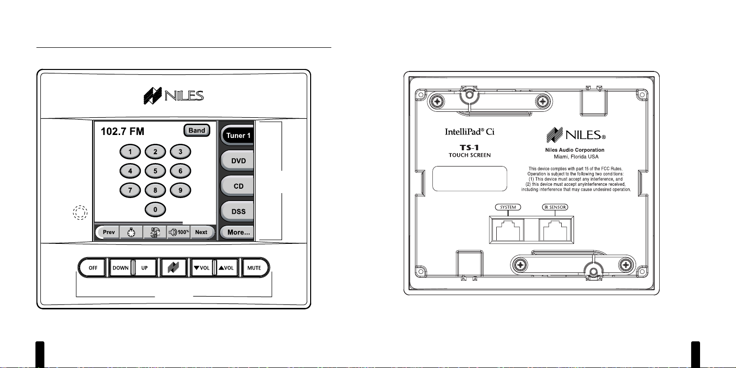
TS-1 Front Description
The TS-1 front contains two types of keys, as shown in Figure 1 on the next page: Hard Keys and
Touch Keys that appear on the back-lit Touch Screen. The Hard Keysare traditional hard-formed keys
and are used to control the most common functions (e.g., volume, see page 8). The Touch Keys
are software-driven and will change functionality (and labels) as you touch them (see page 9).
In addition, an IR Sensor and a PROGRAM Jack (for installers) are hidden under the faceplate. The
IR Sensor communicates with a (optional) Niles R-4 or R-8 Remote Control so you can conveniently
operate the TS-1 at a distance. The PROGRAM Jack allows an installer to set custom features on the
TS-1 when using a connected laptop PC and our TS-1 programming software.
continued on next page...
I NTELLIP AD®Ci TOUCH
S CREEN K EYPAD
4
INTRODUCTION
The Niles TS-1 Touch Screen Keypad is designed as an elegant alternative to the IntelliPad®Ci
Keypads used with Niles Multi-Zone Systems. The TS-1 has an easy-to-read, wall-mounted user
interface and is an ideal choice for home areas where the multi-zone system will be used the most
(e.g., kitchen, master bedroom, family room, etc.). This Installation Guide covers the physical
installation, operation, and manual programming of the TS-1. For detailed system connection
information, refer to the Niles Multi-Zone Control System Installation and Operation Guide for
the ZR-4630, ZR-8630AV, or A4.6Ci system.
FEATURES AND BENEFITS
• Plug-and-Play Operation – Auto-configuration provides for immediate operation upon
connection with no additional programming
• Real-time System Status Information – Displays system status including volume and
radio station information
• High-Resolution LCD Screen – Makes the TS-1 easy to see, understand, and operate
• Favorite Function Keys – Provides one-touch access to favorite programming like radio
stations, satellite or cable TV channels
• Built-in Plasma-Proof IR Sensor – Gives users system operation from hand-held IR
remote controls
• Back-Lighted Hard Keys – Facilitates quick access to frequently used system functions
• Pre-defined Source Component Control Screens – Accommodates all of today’s popular
source components
• Manual System Programming – Provides system customization from the touch screen
• Keypad Connections Use Cat-5 Wiring and Terminate in RJ-45 Connectors –
For ease of installation and system pre-wiring
• Firmware Updates in the Field – Enables feature updates as they become available
• Optional New-Construction Installation Bracket (FG01060)
Page 4
I NTELLIP AD®Ci TOUCH
S CREEN K EYPAD
7
TS-1 Rear Description
The TS-1 rear has two CAT-5 jacks for connection to a Niles Multi-Zone System (i.e., ZR-4630,
ZR-8630AV, or A4.6Ci) and an (optional) external IR sensor, as shown in Figure 2.
Figure 2
TS-1 rear.
I NTELLIP AD®Ci TOUCH
S CREEN K EYPAD
6
DESCRIPTION/OPERATION OVERVIEW
TS-1 Front Description (continued)
Figure 1
TS-1 front (shown with faceplate installed).
Hard Keys
IR Sensor
(under VOL keys)
PROGRAM Jack
(under faceplate)
Touch Keys
(examples)
Touch
Screen
Page 5
I NTELLIP AD®Ci TOUCH
S CREEN K EYPAD
9
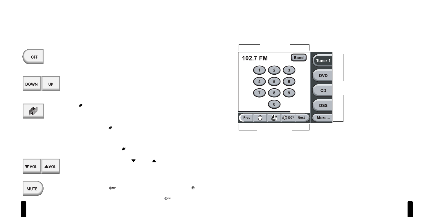
Touch Key Organization
The TS-1 Touch Screen is organized into three different groups of Touch Keys: Navigation Keys,
Master Keys, and Function Keys, as shown in Figure 3.
Figure 3
Organization of an example TS-1 Touch Screen.
NOTE: In any zone, the TS-1 will go into “Standby” after 30 seconds of inactivity and the Touch
Screen will become blank. To activate it, simply touch any part of the Touch Screen or a Hard Key.
continued on next page...
Navigation Keys
Function Keys
Master
Keys
I NTELLIP AD®Ci TOUCH
S CREEN K EYPAD
8
DESCRIPTION/OPERATION OVERVIEW (continued)
TS-1 Operation Overview
Hard Key Operation
Press
OFF
once to turn off the zone you are in. After 30 seconds, the
touch screen will go blank and the Hard Key backlights will turn off.
To turn off all zones, press and hold
OFF
for at least 3 seconds until
you see the Hard Keys flash three times.
After selecting a Master Key, press
DOWN
or UPto select a previous
or next function such as: preset station on a tuner, chapter on a DVD
or LD, track on a CD or media server, or channel on DSS. Also see the
TS-1 Programming Worksheets for exact programming details.
Press (
Zone On
) once to turn on the zone you are in and all Hard
Keys will backlight blue. Also, depending on programming, the Touch
Screen will highlight either a specified or last-selected Master Key and
show its first control screen.
Pressing and holding (
Zone On
) for more than 3 seconds will turn
on the zone you are in and turn on all other zones, as set by the ALL
ON/PAGE switch (see
the appropriate Niles Multi-Zone Control System
Installation and Operation Guide
). In newly-activated zones, the Touch
Screen will be blank and only (
Zone On
) will be backlit blue.
After selecting a Master Key, press
VOL
or
VOL
to set the audio
level. The
Zone Volume
indicator (see page 12) will show the current
volume setting (not available on the A4.6Ci
Multi-Zone Control System).
Press
MUTE
once to mute the audio in the zone you are in. The key will
backlight red and the (
Zone Volume
) indicator will change to
to indicate muting. To unmute audio, press
MUTE
once again. It will
again backlight blue and
Zone Volume
will display .
NOTE: The actual percentage displayed will be the current volume setting.
Page 6
I NTELLIP AD®Ci TOUCH
S CREEN K EYPAD
11
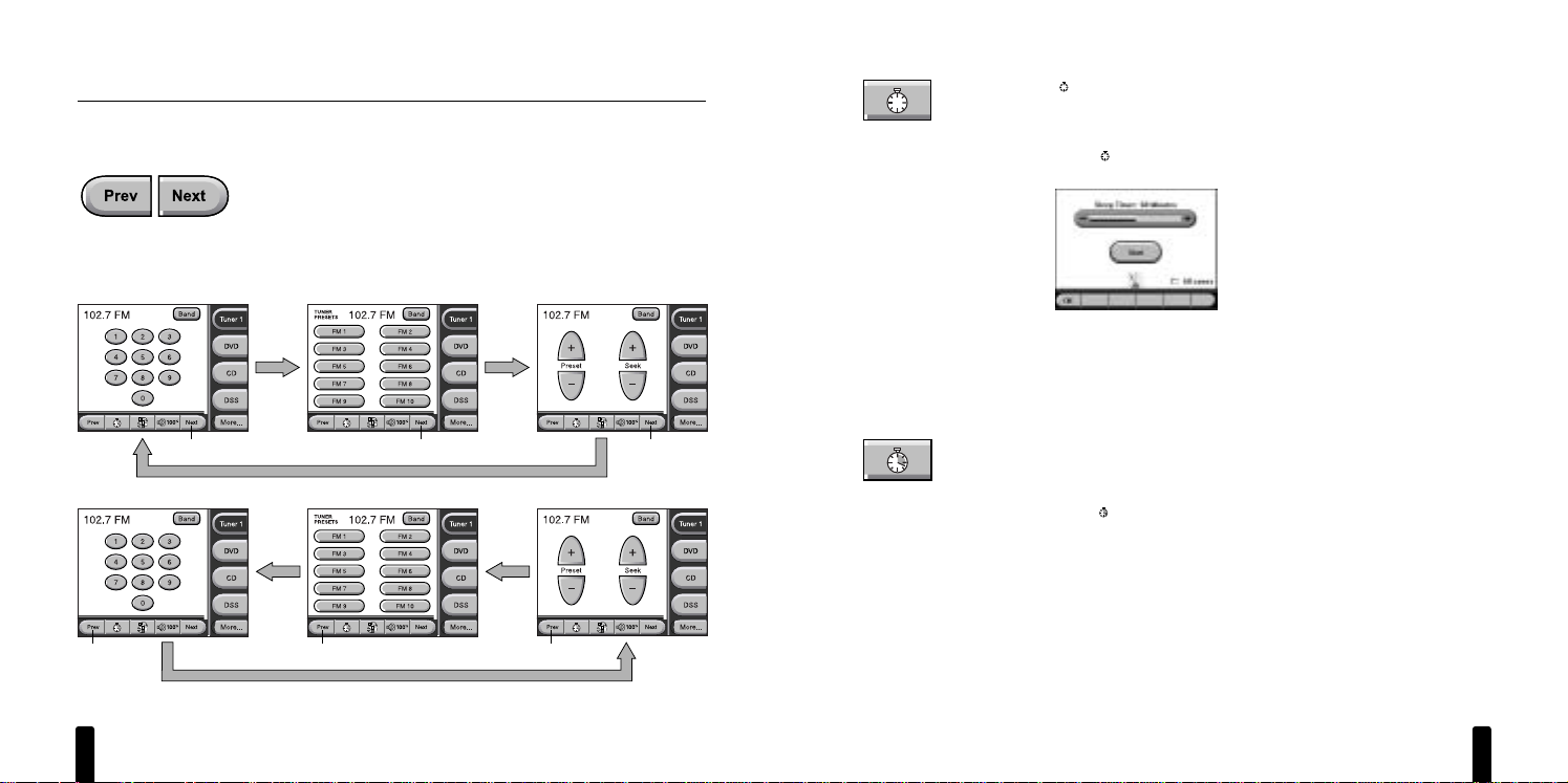
Use (
Sleep Timer
) when you want the TS-1 to automatically turn off
a zone after a preset length of time.
To activate Sleep Timer:
1. Touch (
Sleep Timer
) once to view the Sleep Timer screen, as
shown in Figure 5.
Figure 5
The Sleep Timer screen.
2. Touch –or +one or more times to decrease or increase the timer
from 5 to 120 minutes.
3. (Optional) To include all zones in the Sleep Timer, touch the
All
zones
check box.
4. Touch
Start
once to start the timer. The metronome will activate.
5. Touch OKto save the settings. The minute hand on the
Sleep
Timer
key will appear to indicate the timer is set.
To de-activate Sleep Timer:
1. Touch (
Sleep Timer
) once to view the Sleep Timer screen.
2. Touch
Stop
once.
3. Touch OKto save the settings.
continued on next page...
I NTELLIP AD®Ci TOUCH
S CREEN K EYPAD
10
DESCRIPTION/OPERATION OVERVIEW
TS-1 Operation Overview (continued)
Navigation Key Operation
Touch
Prev
or
Next
once to view the previous or next Control Screen
for a selected Master Key. Touch either key once again to view a different Control Screen. The program will loop back to the original Control
Screen when all have been displayed, as shown in Figure 4 below.
NOTE: Not all source components will have the same number of Control
Screens. See the “TS-1 Programming Worksheets” for details.
Figure 4
Navigating TS-1 Control Screens for an example Niles ZR Tuner.
Touch Touch Touch
Touch Touch Touch
Page 7
I NTELLIP AD®Ci TOUCH
S CREEN K EYPAD
13
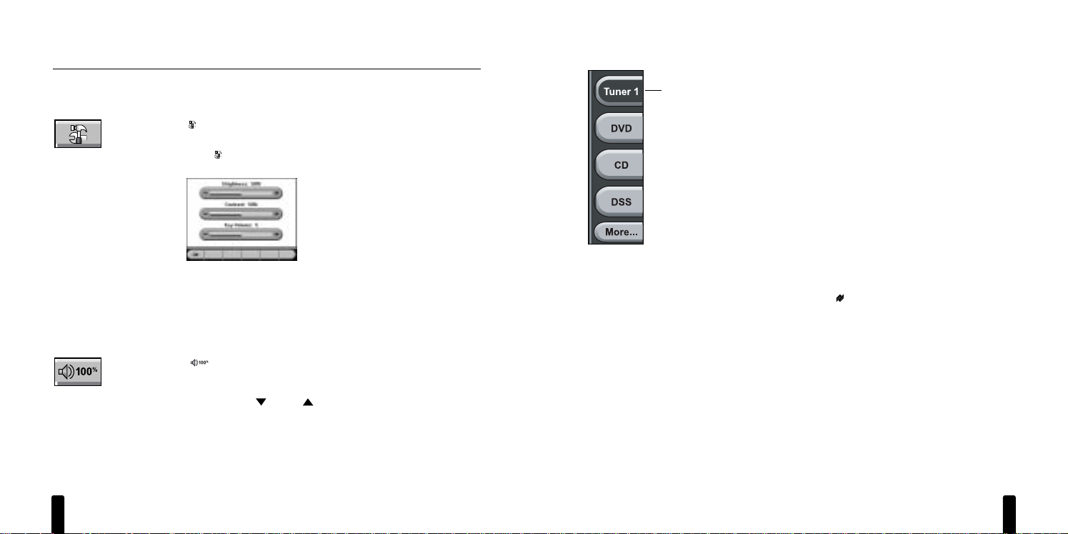
Master Key Operation
When using a ZR-8630AV or A4.6Ci Multi-Zone System, as many as
eight Master Keys will be displayed with up to four keys shown at a
time. When using the ZR-4630 Multi-Zone System, as many as four
Master Keys will be displayed.
• For a ZR-8630AV or A4.6Ci Multi-Zone System, touch
More
(If
displayed) once to view the other set of keys.
•Touch
More
once more to return to the original set.
Touching a Master Key turns on the zone and highlights the key to
indicate the source component is now active (see
Tuner 1
example
on left). At the same time, the first Control Screen for the selection will
be displayed. See Navigation Key Operation (starting on page 10) to
learn how to view other Control Screens.
Pressing and holding a Master Key for more than 3 seconds will turn
on the zone you are in and turn on all other zones, as set by the ALL
ON/PAGE switches (see
the appropriate Niles Multi-Zone Control System
Installation and Operation Guide
). In newly-activated zones, the Touch
Screen will be blank and only (
Zone On
) will be backlit blue.
Active
I NTELLIP AD®Ci TOUCH
S CREEN K EYPAD
12
DESCRIPTION/OPERATION OVERVIEW
TS-1 Operation Overview
Navigation Key Operation (continued)
Use (
Setting Options
) to adjust attributes of the Touch Screen such
as: Brightness, Contrast, or Key Volume (when a key is touched).
1. Touch (
Setting Options
) once to view the Setting Options screen,
as shown in Figure 6.
Figure 6
The Setting Options screen.
2. Touch –or +one or more times to decrease or increase the desired
attribute. For Brightness or Contrast, the adjustment level ranges
from 0 to 100 %. For Key Volume, the adjustment level ranges from
0 to 10.
3. Touch OKto save the settings.
The (
Zone Volume
) indicator displays the current volume level
(of the zone you are in) as a percentage, with 100 % being maximum.
The display will update (not available on the A4.6Ci
Multi-Zone Control
System)
as you use
VOL
or
VOL
to set a desired audio level
.
NOTE: The volume indicator does not display until volume is changed for
the first time after the zone is on.
Page 8

I NTELLIP AD®Ci TOUCH
S CREEN K EYPAD
14
DESCRIPTION/OPERATION OVERVIEW
TS-1 Operation Overview (continued)
Function Key Operation
Each source component has a unique number of functions keys assigned for its control.
Depending on the selected audio or video component and programming, up to seven control
screens may be available for your use.
For example, Figure 4 on page 10 shows three Control Screens for a Niles ZR Tuner: FM Favorites,
Tuner Direct Access, and Tuner Control. You can navigate to other screens by simply touching
Prev
or
Next
one or more times.
We’ve designed all Touch Keys to look and act like the controls found on a component and its
remote control. Simply touch a desired key and the function will activate.
Other control screens, such as CD and DVD players, will also include disc transport keys (e.g.,
Play, Stop, Pause, etc.). A DSS component will have navigation keys and keys for accessing the
electronic program guide. For detailed technical information on all touch screens for all source
components, refer to the TS-1 Programming Worksheets (see page 30).
I NTELLIP AD®Ci TOUCH
S CREEN K EYPAD
15
Understanding Feedback Messages
The TS-1 includes several Feedback Messages that appear under certain conditions to help guide
you when operating a desired function, as shown in Figure 7. Some serve as indicators while
others serve to alert you to a condition.
Figure 7
TS-1 Feedback Messages and their indications.
Feedback Message Indication
• No light = Zone is off.
• Blue light (steady), Touch Screen off = Zone is on.
• Blue light (steady), Touch Screen on, Master Key highlighted =
Zone is on.
• Blue light (steady), Touch Screen on, Master Key not highlighted =
Zone is off.
• Blue light (slow flashing) = Zone is being paged.
• Blue light (flickers) = TS-1 is receiving IR commands from R-8 or
R-4 remote control.
• Red Light = Zone volume is muted.
• Zone volume is muted.
• Sleep timer is on.
The system is busy. • System is being used by another person. Please try again.
This source is currently • When displayed, use discretion before
changing a source’s
selected in another zone
functions (e.g.,
CD track ). Doing so will disrupt someone
(n/a for A4.6Ci
System).
else’s viewing and/or
listening enjoyment in another zone.
The currently selected • Although the TS-1 does not display or allow control of the selected
source is not programmed source in this zone, you still can enjoy viewing and/or listening to the
for display or control on source’s output.
this Touch Pad.
Page 9

I NTELLIP AD®Ci TOUCH
S CREEN K EYPAD
17
SYSTEM CONFIGURATIONS
Application Considerations
The Niles TS-1 Touch Screen Keypad is designed as an alternative to the IntelliPad®Ci Keypads
(i.e., Solo, Solo IR, Select, Select IR, Numeric, or Transport). Either or both can be used in a Niles
Multi-Zone System, such as the ZR-4630, ZR-8630AV, or A4.6Ci. Using standard CAT-5 cables,
interconnection is straightforward and will only require an optional TSP-1 Power Module when
more than three TS-1s are connected to a single multi-zone receiver or preamplifier (see Figure 10
on page 19). To help plan a system, we’ve included the following four applications for your review .
Connecting TS-1s in a Basic System
Figure 8
Three TS-1s are shown connected in a basic multi-zone system.
I NTELLIP AD®Ci TOUCH
S CREEN K EYPAD
16
DESCRIPTION/OPERATION OVERVIEW (continued)
Cleaning the TS-1
The TS-1 includes a Cleaning Mode program so you can temporarily turn off the Touch Screento
clean dust and grime. For normal cleaning, use a dry, soft cloth to wipe off the dirt. To remove
excessive fingerprints or other contamination, first moisten the cloth with water or a windowcleaning solution (e.g., Windex®), wring out the excessive liquid, and then wipe the TS-1.
NOTE: Do not use any other cleaning products. Do not spray any liquid directly onto the TS-1. Doing
so may damage the unit.
1. Press
OFF
to turn off the zone.
2. Press and hold
MUTE
until it starts to flash slowly. At this point, you have 15 seconds to clean
the TS-1.
3. When
MUTE
starts flashing rapidly, the program will automatically exit the Cleaning Modein
5 seconds.
4. If you need more time, press
MUTE
once more while it’s flashing to reset the timer. Repeat
this step as needed until all your cleaning is done.
Page 10

I NTELLIP AD®Ci TOUCH
S CREEN K EYPAD
19
Using a TSP-1 Power Module to Connect Additional TS-1s
Figure 10
A TSP-1 Power Module supplies power to additional TS-1s in a basic multi-zone system.
I NTELLIP AD®Ci TOUCH
S CREEN K EYPAD
18
SYSTEM CONFIGURATIONS (continued)
Using an IntelliPad®Ci Expander™ in a Single Zone
Figure 9
An IntelliPad Ci Expander is used to connect up to three TS-1s in a single zone.
Page 11

I NTELLIP AD®Ci TOUCH
S CREEN K EYPAD
21
INSTALLATION CONSIDERATIONS
Tools and Precautions
We recommend using the following tools to install a TS-1 Keypad:
• Electric drill with 1⁄ 4" and 1⁄2" drill bits, and a 1" flat drill bit (for drilling through studs)
• Keyhole or drywall saw
• Stiff wire, fish tape, or glow rods (for routing cables)
• Philips screwdriver set
• Cable ties
• Pencil
• Level
• Rubber gloves and protective eyewear
Before starting the installation, please observe the following precautions:
•Turn off all system power before making any connections.
• Always wear protective eyewear when using tools.
• Make sure hands are clean before installation.
•Wear gloves when working with fiberglass insulation.
Where to Mount a TS-1 Keypad
Convenient mounting locations for the
TS-1 Keypad
include:
• Near entry ways or exits
• Near a desk
• At a bedside
• Close to a telephone
•Near other wall controls
continued on next page...
SYSTEM CONFIGURATIONS (continued)
Adding an External IR Sensor
Figure 11
An (optional) external IR Sensor is shown connected to a TS-1 using four-pair twisted (CAT-5) cable.
I NTELLIP AD®Ci TOUCH
S CREEN K EYPAD
20
Page 12

I NTELLIP AD®Ci TOUCH
S CREEN K EYPAD
23
Figure 12
TS-1 mounting heights and optimal viewing angles for people of different heights.
I NTELLIP AD®Ci TOUCH
S CREEN K EYPAD
22
INSTALLATION CONSIDERATIONS
Where to Mount a TS-1 Keypad (continued)
Avoid installing the TS-1 Touch Screen Keypad in the following areas, which can degrade operation or accessibility:
• In direct sunlight or strong ultraviolet light
• Over heat-generating or moist areas
• Behind an opened door
• Next to a thermostat (since the TS-1 generates heat that can affect thermostat settings)
CAUTION: Do not install the TS-1 into electrical boxes with 110-volt devices.
Some states or municipalities allow devices such as the TS-1 Keypad to be installed into the same
electrical box with 110-volt devices, provided a “low-voltage partition” is used between the
devices.
We do not recommend this action. If you must locate a TS-1 Keypad near electrical devices, install
it in a separate metal electrical box, ground the box to the electrical system ground, and route the
speaker wires several feet away from the electrical wiring.
Recommended Mounting Height
The TS-1 Keypad is designed with a viewing angle of 42°, as shown in Figure 12 on the next page.
NOTE: The recommended mounting height depends on the user’s height and distance from the TS-1.
Before mounting, determine the average height of all users to find a mounting height that will
work best. As an example, for a 6' person standing about 2' away, mount the TS-1 at 60" above
the floor (see Figure 12). For a 5' person, use a mounting height of 48".
Page 13

I NTELLIP AD®Ci TOUCH
S CREEN K EYPAD
25
Installing the TS-1 in New Construction
For a new construction site, use our optional New Construction Bracket (FG01060) to provide a
support for mounting the TS-1 on new drywall, as shown in Figure 14.
Figure 14
Using the optional New Construction Bracket (FG01060) to install a TS-1 in new construction.
continued on next page...
I NTELLIP AD®Ci TOUCH
S CREEN K EYPAD
24
INSTALLATION CONSIDERATIONS (continued)
Installing the TS-1 in Existing Construction
1. At a proposed site, use the enclosed wall template to mark the outline of the TS-1. Check for
hidden obstructions by drilling a small hole in the drywall at the center of the outline. If you
feel any obstructions while drilling, stop immediately and select another site.
2. Bend a piece of stiff wire (e.g., coat hanger) about 6 inches from the end at a 90-degree angle.
Insert the bent end into the hole and rotate the wire to check if there are any other obstructions. If you hit anything, patch the hole with drywall compound and choose another site.
3. Connect the CAT-5 cable(s) to the TS-1’s rear jack(s) (see Connecting the TS-1 on page 27).
IMPORTANT: Test cable prior to connection, miswired and damaged cables can cause dam-
age to the TS-1.
4. The TS-1 is equipped with two Mounting Clamps for easy installation. Hold the TS-1 firmly in
the opening and use a Phillips screwdriver to turn each mounting-clamp screw to the right
until the TS-1 feels fastened, as shown in Figure 13.
NOTE: Do not overtighten the mounting-clamp screws.
Figure 13
Using the TS-1’s built-in mounting clamps.
Page 14

INSTALLATION CONSIDERATIONS
Installing the TS-1 in New Construction (continued)
1. At a proposed site, install a New Construction Bracket to studs with nails or metal screws.
2. Use a cable tie to attach the CAT-5 cable(s) to the bracket at about 6" from the end(s) (see
Figure 14 on the previous page).
3. After drywall has been installed, use a drywall saw to cut out the opening (i.e., 4" h x 4.75" w)
for the TS-1.
4. Connect the CAT-5 cable(s) to the TS-1’s rear jack(s) (see Connecting the TS-1 on page 27).
IMPORTANT: Test cable prior to connection, miswired and damaged cables can cause dam-
age to the TS-1.
5. The TS-1 is equipped with two Mounting Clamps for easy installation. Hold the TS-1 firmly in
the opening and use a Phillips screwdriver to turn each mounting-clamp screw to the right
until the TS-1 feels fastened, as shown in Figure 13 on page 24.
NOTE: Do not overtighten the mounting-clamp screws.
I NTELLIP AD®Ci TOUCH
S CREEN K EYPAD
26
I NTELLIP AD®Ci TOUCH
S CREEN K EYPAD
27
CONNECTING THE TS-1
Wiring Considerations
There are three distinct ways you can run CAT-5 cables between components in the system.
Attic/Basement Run
Drill a hole through the stud that caps the wall. Then run the cable from the attic or basement
and, using a fish tape, pull it up or down through the wall to the TS-1 opening.
Baseboard Run
Run the CAT -5 cable along or behind baseboards and then through the wall at the floor (below the
TS-1) and up to the opening.
Channel Drywall Run
Route out a shallow horizontal groove directly in the wallboard and lay the CAT-5 cable in the
channel. Then thread the cable behind the drywall between the studs to the TS-1. After the
installation is complete, patch the channels and any openings with a drywall compound.
TS-1 Connections
Each TS-1 has two CAT-5 jacks on its rear panel, as shown in Figure 2 on page 7.
• Using a CAT-5 cable, connect
SYSTEM
as a home run to the appropriate zone jack on the
Niles Multi-Zone System. For wiring consistency, follow the color codes shown in Figure 15.
(Please refer to IMPORTANT warning on pages 24, 26).
Figure 15
Color codes for RJ-45 connector.
continued on next page...
Page 15

I NTELLIP AD®Ci TOUCH
S CREEN K EYPAD
29
NOTE: An IR Sensor is required when the built-in TS-1 IR Sensor is not located in an ideal location
in a zone, or when pass-through IR commands (instead of Niles system commands) are needed to
control a source component.
Figure 17
Connecting an (optional) IRR-4D+ IR Sensor to the TS-1 Keypad.
I NTELLIP AD®Ci TOUCH
S CREEN K EYPAD
28
CONNECTING THE TS-1
TS-1 Connections (continued)
• Connect
IR SENSOR
to an (optional) external IR Sensor, as shown in Figure 16 below or
Figure 17 on the next page.
Figure 16
Connecting an (optional) WS100R IR Sensor to the TS-1 Keypad.
Page 16

I NTELLIP AD®Ci TOUCH
S CREEN K EYPAD
31
Figure 19
Steps 5 and 6 of this TS-1 System Programming Worksheet show example information filled in for Master Key
Labels, Source Components, and the Zone On Command Assignment.
continued on next page...
MANUALLY PROGRAMMING THE TS-1
The TS-1 can be programmed manually by using a built-in utility program. It provides a series of
control screen templates containing source-component function keys for audio and video sources
which can be modified and customized by the installer.
Within the program, the installer can customize labels for Master Keys and Function Keys or hide
them from view via the Edit Configuration function. In addition, the installer can automatically
configure the TS-1 by selecting the Auto Configure function.
NOTE: All Hard Keys except (
Zone On
) will be disabled during Manual Programming.
Documenting Programming Worksheets
Before editing a configuration, we recommended documenting the programming on copies of
the TS-1 Programming Worksheets for the system and component screen sets. Figures 18 through
21 (on pages 30 to 33) show examples of how to fill out the information step-by-step for each
type of worksheet. (You can download the worksheets at www.nilesaudio.com).
Figure 18
Steps 1 through 4 of this TS-1 System Programming Worksheet show example information filled in for Job Title,
Date, System Designer, and the Show Settings Option.
I NTELLIP AD®Ci TOUCH
S CREEN K EYPAD
30
Page 17

Function Key Show Key Label Niles Command
Play ❏ ____________________ Play
Stop
❏ ____________________ Stop
Pause
❏ ____________________ Pause
Next Track ❏ ____________________ Surf +
Right Track ❏ ____________________ Surf -
Scan >> ❏ ____________________ FF
Scan << ❏ ____________________ Rew
Slow > ❏ ____________________ FM
Slow < ❏ ____________________ AM
Function Key Text
Scan ❏ ____________________
Disc Skip
❏ ____________________
Function Key Show Key Label Niles Command
Setup ❏ ____________________ M
Menu ❏ ____________________ G
Up ❏ ____________________ Up
Select ❏ ____________________ *
Down ❏ ____________________ Down
Left ❏ ____________________ Left
Right ❏ ____________________ Right
Return ❏ ____________________ E
OSD ❏ ____________________ P
Function Key Show Key Label Niles Command
Disc ❏ ____________________ Disc
Group
❏ ____________________ Group
Rdm
❏ ____________________ Random
Enter
❏ ____________________ *
1
❏ ____________________ 1
2
❏ ____________________ 2
3
❏ ____________________ 3
4
❏ ____________________ 4
5
❏ ____________________ 5
6
❏ ____________________ 6
7
❏ ____________________ 7
8
❏ ____________________ 8
9
❏ ____________________ 9
0
❏ ____________________ 0
10
❏ ____________________ -
+100
❏ ____________________ +
DVD
SCREEN 1
DVD
SCREEN 2
DVD
SCREEN 3
Search
✓
✓
✓
✓
✓
✓
✓
✓
✓
✓
✓
✓
✓
✓
✓
✓
✓
✓
✓
✓
✓
✓
✓
✓
✓
✓
✓
✓
✓
✓
✓
✓
✓
✓
✓
Enter
Display
I NTELLIP AD®Ci TOUCH
S CREEN K EYPAD
33
Figure 21
This portion of the Master Key Programming
Worksheet for the DVD Screen Set shows example
information (such as Show Key settings and
Label renaming) filled in for the three DVD screens.
Master Key Programming Worksheets for other
components may have as many as four screen sets,
as well as different types of function keys.
NOTE: The
Down and Up hard keys are not listed
in the screen sets. These function keys are the same
for all components and issue Surf- and Surf+
commands, respectively.
MANUALLY PROGRAMMING THE TS-1
Documenting Programming Worksheets (continued)
Figure 20
Steps 1 through 4 of this Master Key Programming Worksheet for the DVD Screen Set show example information
filled in for Job Title, Date, System Designer, and Master Key Number and Label.
I NTELLIP AD®Ci TOUCH
S CREEN K EYPAD
32
MASTER KEY PROGRAMMING WORKSHEET
DVD SCREEN SET
1
JOB TITLE
2
DATE
TS-1
3
SYSTEM DESIGNER
4
MASTER KEY NUMBER AND LABEL
MASTER KEY #: —
Mr. Smith
Joe Installer
9-30-2003
2 DVD
Page 18

I NTELLIP AD®Ci TOUCH
S CREEN K EYPAD
35
Calibrating the TS-1 Screen
1. On the Manual Programming screen (see previous page, step 2), touch
Calibrate Screen
once. The Screen Calibration screen will appear:
2. Touch each of the targets as they appear. The screen will calibrate and the Manual
Programming screen will appear again.
3. If finished with all manual programming, touch
OK
once to exit the program. Otherwise,
continue with other program options.
Using Auto Configure
When a Niles Multi-Zone System is first activated, each connected TS-1 automatically configures
itself to match the multi-zone controller. However, if a TS-1’s display remains blank or (after editing
a configuration) you want to reset a TS-1 to a basic system, then perform the following steps:
1. On the Manual Programming screen (see previous page, step 2), touch
Auto Configure
once. A warning dialog box will appear:
continued on next page...
MANUALLY PROGRAMMING THE TS-1 (continued)
Starting the Utility Program
1. Touch (
SLEEP TIMER
) once. The Sleep Timer screen will appear:
Metronome Icon
2. Touch and hold the Metronome Icon for at least 3 seconds. The Manual Programming screen
will appear:
3. At this point the installer can choose from several program options, including: Auto Configure,
Edit Configuration, Send Configuration, Calibrate Screen, and Show Settings Option. Each option
will be described in its own section on the pages that follow.
I NTELLIP AD®Ci TOUCH
S CREEN K EYPAD
34
Page 19

I NTELLIP AD®Ci TOUCH
S CREEN K EYPAD
37
Configuring Master Keys
1. Touch any of the displayed Master Keys twice. If needed, touch
More
once to view the other
set of Master Keys. The Master Key Edit screen will appear (as shown in the following example):
• For reference, the Master Key Edit screen shows the command name (e.g.,
MK3
) for the
selected Master Key.
•To show a selected Master Key during normal TS-1 operation, touch
Show Key
once.
A check mark will appear in the check box.
NOTE: For a ZR-4630 Multi-Zone Control System, only the first four Master Keys can
be shown.
•To hide a selected Master Key during normal TS-1 operation, touch
Show Key
once. The
check mark will disappear from the check box.
•To edit the label for the selected Master Key, touch
Edit
once. A keyboard will appear. Use
a PDA stylus to type in a desired label. When finished, touch
ENTER
once to save your entry
and return to the Master Key Edit screen. The highlighted Label box will display your entry.
•To edit the type of control screens that will appear for the selected Master Key, touch
▲
or ▼one or more times to scroll and locate a desired set of control screens. The highlighted Screens box will display your selection.
2. Touch OKonce to save the settings. The Edit Configuration screen will appear again.
3. To save all
Edit Configuration
settings, touch
Exit
once. The Manual Programming screen
will appear again.
4. If finished with all manual programming, touch OKonce to exit the program. Otherwise,
continue with other program options.
continued on next page...
MANUALLY PROGRAMMING THE TS-1
Using Auto Configure (continued)
2. Select the desired action as follows:
•To continue with auto configuration, touch
Yes
once. The TS-1 will reconfigure itself and
the Manual Programming screen will appear again.
•To cancel auto configuration, touch Noonce. The action will be cancelled and the Manual
Programming screen will appear again.
3. If finished with all manual programming, touch OKonce to exit the program. Otherwise,
continue with other program options.
Editing the TS-1 Configuration
Included in the TS-1’s built-in utility program is an Edit Configuration module. It allows the installer
to modify and customize control screen templates containing source-component function keys for
audio and video sources.
1. On the Manual Programming screen (see page 34, step 2), touch
Edit Configuration
once.
The Edit Configuration screen will appear:
2. At this point, the installer can choose to configure Master Keys (see next page) or Function
Keys (see page 38).
I NTELLIP AD®Ci TOUCH
S CREEN K EYPAD
36
Page 20

I NTELLIP AD®Ci TOUCH
S CREEN K EYPAD
39
•To edit the label for the selected Function Key, touch
Edit
once. A keyboard will appear. Use
a PDA stylus to type in a desired label. When finished, touch
ENTER
once to save your entry
and return to the Function Key Edit screen. The highlighted Labelbox will display your entry .
3. Touch OKto save the settings. The Edit Configuration screen will appear again.
4. To save all
Edit Configuration
settings, touch
Exit
once. The Manual Programming screen
will appear again.
5. If finished with all manual programming, touch OKonce to exit the program. Otherwise,
continue with other program options.
6. (Optional) For ZR receivers only, perform Sending the Configuration to Other TS-1s on the next
page to send the new settings to other connected TS-1s.
Setting the Zone ON Key
(
Zone On
) can be programmed to select the last-selected Master Key or a pre-selected Master
Key as follows:
1. On the Manual Programming screen (see page 34, step 2), touch
Edit Configuration
once.
The Edit Configuration screen will appear:
2. Press (
Zone On
) once. The Zone On Edit screen will appear:
continued on next page...
MANUALLY PROGRAMMING THE TS-1
Editing the TS-1 Configuration (continued)
Configuring Function Keys
1. Touch a desired Master Key once (e.g.,
DVD
). If needed, touch
More
once to view the other
set of Master Keys. The first Control Screen for the selected component will appear (as shown
in the following example):
NOTE: Certain screen sets contain Favorite Function Keys that can
not be configured manually and must be programmed using a laptop PC and the TS-1 Programming Software. Favorite function keys
are hidden by default.
2. Touch
Prev
or
Next
one or more times to display a control screen you want to edit. Touch
a desired Function Key once (e.g.,
Play
). The Function Key Edit screen will appear:
• For reference, the Function Key Edit screen shows the command name (e.g.,
Play
) for the
selected Function Key.
•To show a selected Function Key during normal TS-1 operation, touch
Show Key
once.
A check mark will appear in the check box
•To hide a selected Function Key during normal TS-1 operation, touch
Show Key
once.
The check mark will disappear from the check box
I NTELLIP AD®Ci TOUCH
S CREEN K EYPAD
38
Page 21

I NTELLIP AD®Ci TOUCH
S CREEN K EYPAD
41
2. On the Manual Programming screen (see page 34, step 2), touch
Send Configuration
once.
3. The new configuration settings will be sent to other connected TS-1s. If an error occurs, a
prompt will appear, so repeat step 2 again.
4. If finished with all manual programming, touch OKonce to exit the program. Otherwise,
continue with other program options.
Figure 22
How to connect a newly-configured TS-1 to a ZR receiver to send data to other connected TS-1s.
TS-1
MANUALLY PROGRAMMING THE TS-1
Setting the Zone ON Key (continued)
3. Touch
Last Selected
or a labeled Master Key once. The associated button will highlight.
4. Touch OKonce to save the setting. The Edit Configuration screen will appear again.
5. Touch
EXIT
once to exit the Edit Configuration screen. The Manual Programming screen will
appear again.
6. If finished with all manual programming, touch OKonce to exit the program. Otherwise,
continue with other program options.
Displaying Settings Option
To Show Settings Option:
1. On the Manual Programming screen (see page 34, step 2), touch
Show Settings Option
once. A check mark will appear in the check box.
2. When finished with manual programming, touch OKonce to save the settings.
3. When the TS-1 Touch Screen returns to normal operation, (
Settings Option
) will appear
on the Navigation Keys.
To Hide Settings Option:
1. On the Manual Programming screen (see page 34, step 2), touch
Show Settings Option
once. The check mark will disappear in the check box.
2. When finished with manual programming, touch OKonce to save the setting.
3. When the TS-1 Touch Screenreturns to normal operation, (
Settings Option
) will no longer
appear on the Navigation Keys and the key will be blank.
Sending The Configuration to Other TS-1s (For ZR Receivers Only)
1. Using a DB9 to mini-plug serial cable and a male-to-male DB9 null-modem adapter, connect
the
PROGRAM
jack on the newly-configured TS-1 to the ZR receiver’s
COMPUTER INTER-
FACE
port, as shown in Figure 22 on the next page.
I NTELLIP AD®Ci TOUCH
S CREEN K EYPAD
40
Page 22

I NTELLIP AD®Ci TOUCH
S CREEN K EYPAD
43
FCC INSTRUCTIONS TO THE USER
This equipment has been tested and found to comply with the limits for a class B digital device,
pursuant to part 15 of the FCC Rules. These limits are designed to provide reasonable protection
against harmful interference in a residential installation.This equipment generates, uses and can
radiate radio frequency energy and if not installed and used in accordance with the instructions,
may cause harmful interference to radio communications. However, there is no guarantee that
interference will not occur in a particular installation. If this equipment does cause harmful interference to radio or television reception, which can be determined by turning the equipment off
and on, the user is encouraged to try to correct the interference by one or more of the following measures:
• Reorient or relocate the receiving antenna.
• Increase the separation between the equipment and receiver.
• Connect the equipment into an outlet on a circuit different from that to which the receiver
is connected.
•Consult the dealer or an experienced radio/TV technician for help.
This equipment has been verified to comply with the limits for a class B computing device, pursuant to FCC Rules. In order to maintain compliance with FCC regulations, shielded cables must
be used with this equipment. Operation with non-approved equipment or unshielded cables is
likely to result in interference to radio and TV reception. The user is cautioned that changes and
modifications made to the equipment without the approval of manufacturer could void the
user's authority to operate this equipment.
MANUALLY PROGRAMMING THE TS-1 (continued)
About Programming with a PC
The TS-1 can also be programmed using a laptop PC and our TS-1 Programming Software. For
more information consult with your Niles dealer.
SPECIFICATIONS
Control
LCD Touch Screen: 3.8" Gray Scale (320 x 240 pixels)
Touch-Screen Viewing Angle: Optimal 42° (see Figure 12 on page 23)
External Hard Keys: Seven Backlit Pushbuttons
IR Sensor: Operates with Niles R-4/R-8 Remote Controls
Connections
System: RJ-45 for CAT-5 Cable to Niles Multi-Zone System
IR Sensor: RJ-45 for Three- and Four-Wire Connection to Niles IR Sensor
Serial: 3.5 mm mini-plug
Power Consumption: 140 mA @ 16V DC
Dimensions
H x W x D: 5-3⁄ 16" x 4-1⁄ 2" x 2-1⁄ 2"
Depth Behind Wall: 1-1⁄ 16" (based on mounting into 1⁄ 2" drywall)
Retrofit Wall Cutout, H x W: 3-7 ⁄8" x 4-3 ⁄ 4"
Shipping weight: 1 lb
Warranty
Two-year limited
I NTELLIP AD®Ci TOUCH
S CREEN K EYPAD
42
 Loading...