


I N S T A L L A T I O N & O P E R A T I O N G U I D E
RVL-6
Modular Multi-Room Controller
Infrared Remote Control Speaker Selection, Volume Control, and Infrared Repeater System


 ®
®
B L E N D I N G H I G H F I D E L I T Y A N D A R C H I T E C T U R E ®
Congratulations!
Thank you for purchasing the Niles RVL-6 Multi-Room Control System, one of the most flexible and convenient audio components ever offered. The RVL-6, like all Niles products, is built to the highest standards of quality and reliability. With proper installation and operation, you'll enjoy years of trouble-free use.
Niles manufactures the industry's most complete line of custom installation components and accessories for audio/video systems. For a free full line catalog write:
Niles, Catalog Request, P.O. Box 160818, Miami, Florida 33116-0818
Table Of Contents
INTRODUCTION . . . . . . . . . . . . . . . . . . . . . . . . . . . . . . . . . . . . . . . . . . . . . . . . . . . . . . . . . . . . . . . . . . . . . . . . . .3 FEATURES AND BENEFITS . . . . . . . . . . . . . . . . . . . . . . . . . . . . . . . . . . . . . . . . . . . . . . . . . . . . . . . . . . . . . . . . . . .4 GETTING TO KNOW YOUR RVL-6 . . . . . . . . . . . . . . . . . . . . . . . . . . . . . . . . . . . . . . . . . . . . . . . . . . . . . . . . . . . .6 THE ROOM CONTROL MODULES . . . . . . . . . . . . . . . . . . . . . . . . . . . . . . . . . . . . . . . . . . . . . . . . . . . . . . . . . . . .7 MAKING THE CONNECTIONS . . . . . . . . . . . . . . . . . . . . . . . . . . . . . . . . . . . . . . . . . . . . . . . . . . . . . . . . . . . . . . .8 SETTING THE DIP SWITCHES . . . . . . . . . . . . . . . . . . . . . . . . . . . . . . . . . . . . . . . . . . . . . . . . . . . . . . . . . . . . . . . .15 OPERATING YOUR RVL-6 SYSTEM . . . . . . . . . . . . . . . . . . . . . . . . . . . . . . . . . . . . . . . . . . . . . . . . . . . . . . . . . . .18 SYSTEM DESIGN BASICS . . . . . . . . . . . . . . . . . . . . . . . . . . . . . . . . . . . . . . . . . . . . . . . . . . . . . . . . . . . . . . . . . . .21 CHOOSING THE RVL-6 SYSTEM THAT IS RIGHT FOR YOU . . . . . . . . . . . . . . . . . . . . . . . . . . . . . . . . . . . . . . . .22 A SINGLE ZONE SYSTEM USING ONE RVL-6 . . . . . . . . . . . . . . . . . . . . . . . . . . . . . . . . . . . . . . . . . . . . . . . . . . .23 A SINGLE ZONE SYSTEM USING UP TO FOUR RVL-6s . . . . . . . . . . . . . . . . . . . . . . . . . . . . . . . . . . . . . . . . . . . .25 A MULTIPLE ZONE SYSTEM USING UP TO FOUR RVL-6s . . . . . . . . . . . . . . . . . . . . . . . . . . . . . . . . . . . . . . . . . .28 A DUAL ZONE SYSTEM USING AN IR REPEATER SYSTEM . . . . . . . . . . . . . . . . . . . . . . . . . . . . . . . . . . . . . . . . . .32 POWERLINE CARRIER CONTROLS . . . . . . . . . . . . . . . . . . . . . . . . . . . . . . . . . . . . . . . . . . . . . . . . . . . . . . . . . . .34 TROUBLESHOOTING GUIDELINES . . . . . . . . . . . . . . . . . . . . . . . . . . . . . . . . . . . . . . . . . . . . . . . . . . . . . . . . . . .37 ROOM CONTROL MODULE TROUBLESHOOTING . . . . . . . . . . . . . . . . . . . . . . . . . . . . . . . . . . . . . . . . . . . . . .37 IR TROUBLESHOOTING . . . . . . . . . . . . . . . . . . . . . . . . . . . . . . . . . . . . . . . . . . . . . . . . . . . . . . . . . . . . . . . . . . .38 SPECIFICATIONS . . . . . . . . . . . . . . . . . . . . . . . . . . . . . . . . . . . . . . . . . . . . . . . . . . . . . . . . . . . . . . . . . . . . . . . . .45
2
Introduction
The RVL-6 is a modular multi-room control system. It combines the benefits of a remote controlled speaker selection/volume control/infrared repeater system into one low-profile chassis. The RVL-6’s unique modular design enables you to design your system to suit your needs. Each RVL-6 can be configured for up to six rooms, and four RVL-6s can be linked in a single system to control up to 24 rooms. Each room is assigned an insertable room control module (sold separately). Choose between a volume control module (includes room on/off control) and a basic room on/off module. You purchase only the room control modules required for your system.
The RVL-6 can be integrated with Niles keypads, programmable IR keypads (the Niles IntelliPad™), IR sensors and powerline carrier controls to deliver the optimum level of control for each room. Additionally, the RVL-6 interfaces with Niles automation products for total convenience.
You’ll never have to worry about overloading an amplifier powering an RVL-6. The RVL-6 constantly monitors which speakers are playing and selects exactly the right amount of impedance protection for your amplifier.
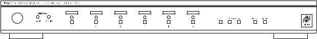
Figure 1 The RVL-6 Multi-Room Controller
3
Features and Benefits
High-Power Handling
The RVL-6 is designed for amplifiers rated at 150 watts per channel continuous (RMS) power. Massive copper traces on the printed circuit-board handle large amounts of amplifier current, ensuring high dynamic-range and clarity. Isolated left and right channel ground returns make the RVL-6 compatible with virtually any amplifier.
Independent Control for Room ON/OFF, VOLUME UP and VOLUME DOWN Commands
The RVL-6 ROOM ON/OFF and VOLUME UP/DOWN commands enable you to control the room you are in without affecting the rest of the system. You can fine tune your listening area without disturbing others in another room.
Global ALL ON and ALL OFF Command
DIP switches on the rear panel of the RVL-6 enable you to individually choose which speakers turn on when the ALL ON command is received. Every room in the system enabled via the ALL ON DIP switches can be turned on instantaneously by issuing the ALL ON command. The entire system can be turned off from any location by issuing the ALL OFF command.
Total Front-Panel Control
The front panel buttons of the RVL-6 enable you to control ROOM ON/OFF and VOLUME UP/DOWN (providing that the correct control module has been installed. When entertaining family and friends, whole-house speaker volume changes are easy and convenient.
Keypad and Hand-Held Remote Control
The RVL-6 can be operated by optional Niles wall-mount keypads (RP-6, RP-7, or the IntelliPad) and/or via Niles IR sensors with hand-held remote controls. The front panel IR sensor of the RVL-6 enables you to control virtually every aspect of your components using a hand-held remote control.
Teaches Learning Remote Controls its IR Commands
All IR commands required to control the RVL-6 can be taught to a learning remote control via the the RVL-6’s teaching IR flasher. This conveniently integrates control of your source components with control of your RVL-6.
IntelliPad-Ready with Power Status Feedback
The RVL-6 communicates the status of each room module to a corresponding IntelliPad, Niles’award-winning programmable IR keypad system. Each IntelliPad in the system displays and controls whether its room is on or off. The IntelliPad’s power synchronization circuitry enables you to create one-touch synchronized sequences to automate your system.
Powerline Carrier Control
Using an optional powerline carrier controller (X-10® or Leviton Decora® Home Control) you can control the RVL-6 through the existing 120V AC electrical wires in your home. An optional Niles TW-523 interface module (Niles stock# FG00256) is required.
4
Modular Construction
The RVL-6 uses insertable room control modules for each room you wish to control giving you optimum flexibility when designing your system. With a single RVL-6 chassis you can control up to six rooms by installing either an RVC-1 VOLUME CONTROL module (Niles stock# FG00247) or a simple RSS-1 ROOM ON/OFF module (Niles stock# FG00248) for each room. You purchase only the number and type of modules you need.
Easy System Expansion
Up to four RVL-6’s can be linked to control systems with up to 24 rooms. When linked, Global ALL ON or ALL OFF commands affect the entire system. In addition, IR commands can be routed to common source equipment from any of the 24 rooms.
Computerized Amplifier Protection
The RVL-6’s programmable microcontroller constantly monitors which room modules are on (you specify each speaker’s impedance, see page 15) and their volume level, then calculates the total impedance and provides the minimum impedance protection your amplifier requires (you specify your amplifier’s requirements, see page 15). This extremely accurate handling of impedance protection maximizes the power for your speakers at all times, while protecting your amplifier from overloading.
Automatic Audiophile Bypass
When only one pair of speakers is playing, the RVL-6 bypasses the impedance protection circuit. This creates the purest possible circuit between the amplifier inputs and the speaker outputs.
Control Output
The 12V DC CONTROL OUT and an optional Niles AC-3 voltage-activated AC power switching system (Niles stock# FG00242) enable your amplifier/receiver to turn on automatically when any of the RVL-6’s room modules are turned on (the amplifier must have a “latching” power switch and non-volatile memory, see page 21). When all of the room modules are turned off, the AC-3 and the amplifier/receiver will be turned off automatically after a 30 second delay. This delay enables the equipment to remain on if an ALL OFF command was inadvertently issued.
Confirm and Status LEDs
The CONFIRM LED flashes green when the RVL-6 receives any IR command. The ROOM STATUS LEDs light green when a room module is turned on. When a green ROOM STATUS LED blinks the corresponding room module is “selected” and ready to be controlled.
Room Identification Labels
Recessed areas above the ROOM STATUS LEDs and buttons accommodate room identification labels enabling you to custom label each room. Seventy-two adhesive-backed room labels are included with your RVL-6.
Proudly Made in the USA
The RVL-6 is made in Miami, Florida and comes with a limited two year parts and labor warranty.
5
Getting To Know Your RVL-6
Because the RVL-6 presents an extensive amount of configuration possibilities it is important to become familiar with all the features and options that are available. A good understanding of the anatomy of the unit will enable you to optimally create, configure and install your system (see Figure 2).
|
|
|
|
|
|
|
|
|
|
|
|
|
|
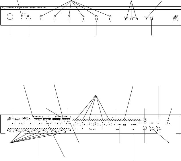
ROOM STATUS LEDs. |
|
||||||||||||||||||
|
|
|
|
|
|
LED BLINKING - The room is selected; you may adjust |
|
||||||||||||||||||||||||||
TEACHING LED teaches Niles |
|
|
|
volume, room on/off, etc. using the front panel controls |
|
||||||||||||||||||||||||||||
IR commands to any learning |
|
|
|
|
|
|
|
|
|
|
|
LED on - The room is on |
|
||||||||||||||||||||
|
remote control |
|
|
|
|
|
|
|
|
|
|
|
LED off - The room is off |
|
|||||||||||||||||||
|
|
|
|
|
|
|
|
|
|
|
|
|
|
|
|
|
|
|
|
|
|
|
|
|
|
|
|
|
|
|
|
|
|
|
|
|
|
|
|
|
|
|
|
|
|
|
|
|
|
|
|
|
|
|
|
|
|
|
|
|
|
|
|
|
|
|
|
|
|
|
|
|
|
|
|
|
|
|
|
|
|
|
|
|
|
|
|
|
|
|
|
|
|
|
|
|
|
|
|
|
|
|
|
|
|
|
|
|
|
|
|
|
|
|
|
|
|
|
|
|
|
|
|
|
|
|
|
|
|
|
|
|
|
|
|
|
|
|
|
|
|
|
|
|
|
|
|
|
|
|
|
|
|
|
|
|
|
|
|
|
|
|
|
|
|
|
|
|
|
ON/OFF and VOLUME controls affect rooms which are “selected” (LEDs are blinking)
ALL ON button enables you to turn on all or some of your speakers depending upon the rear panel DIP switch settings
|
|
|
|
|
|
|
|
|
|
|
|
|
|
|
|
|
|
|
|
|
|
|
|
|
|
|
|
|
|
|
|
|
|
|
|
|
|
|
|
|
|
|
|
|
|
|
|
|
|
|
|
|
|
|
|
|
|
|
|
|
|
|
|
|
|
|
|
|
|
|
|
|
|
|
|
|
|
|
|
|
|
|
|
|
|
|
|
|
|
|
|
|
|
|
|
|
|
|
|
|
|
|
|
|
|
|
|
|
|
|
|
|
|
|
|
|
|
|
|
|
|
|
|
|
|
|
|
|
|
|
|
|
|
|
|
|
|
|
|
|
INFRARED |
CONFIRM LED flashes green |
ROOM SELECT buttons allow you to “select” |
|
|
|
|
ALL OFF button turns off |
|
|
|||||||||
|
SENSOR |
whenever an IR signal or |
rooms singly or in combinations. Once a room(s) is |
|
|
|
|
your entire system |
|
|
|||||||||
controls Room 1 interference is received from any |
selected, you may control it with the ON/OFF and |
|
|
|
|
|
|
|
|
|
|
|
|
|
|||||
|
module |
IR sensor |
VOLUME UP and VOLUME DOWN buttons |
|
|
|
|
|
|
|
|
|
|
|
|
|
|||
AMP IMPEDANCE DIP |
|
ALL-ON DIP switches enable you to select |
|
|
|
|
|
|
DEDICATED FLASHER |
|
|
UART jack for ALL ON and |
|||||||||||||||||||||||||||||||||||||||||||||||||||||||||||||
switches enable you to |
which rooms are activated when the ALL-ON |
|
|
|
|
|
|
output controls compo- |
|
|
ALL OFF commands when |
||||||||||||||||||||||||||||||||||||||||||||||||||||||||||||||
match the RVL-6 to your |
|
|
|
|
|
|
|
|
|
|
|
command is issued |
SENSOR/KEYPAD |
nents which are dedicat- |
|
|
multiple RVL-6 are used |
||||||||||||||||||||||||||||||||||||||||||||||||||||||||
amplifier’s ideal load |
|
|
|
|
|
|
|
|
|
|
|
|
|
|
|
|
|
|
|
|
|
|
|
|
|
|
|
|
|
|
|
connections corre- |
|
ed to this RVL-6 |
|
|
|
|
within one system |
||||||||||||||||||||||||||||||||||
|
|
|
|
|
|
|
|
|
|
|
|
|
|
|
|
|
|
|
|
|
|
|
|
|
|
|
|
|
|
|
|
|
|
|
|
|
|
|
|
|
|
|
|
|
sponding to each of |
|
|
|
|
|
|
|
|
|
|
|
|
|
|
|
|
|
|
|
|
|
|
|
|||||
|
|
|
|
|
|
|
|
|
|
|
|
|
|
MODE switches |
|
|
|
|
|
|
|
VOLUME DIP |
the Room Control |
|
|
|
|
|
|
|
|
|
|
|
|
|
|
|
|
|
|
|
|
|
|
|
|||||||||||||||||||||||||||
|
|
|
|
|
|
|
|
|
|
|
|
|
|
|
|
|
|
|
|
|
|
|
Modules |
|
|
|
|
|
|
|
|
|
|
|
|
|
|
|
|
|
|
|
|
|
|
|
|||||||||||||||||||||||||||
|
|
|
|
|
|
|
|
|
|
|
|
|
|
|
|
control the |
|
|
|
|
|
|
chooses whether |
|
|
|
|
|
|
|
|
|
|
|
|
|
|
|
|
|
|
|
|
|
|
|
|
|
|||||||||||||||||||||||||
Screw-locked |
|
|
|
|
|
|
|
|
|
|
|
|
|
|
|
|
|
|
|
|
|
|
|
|
|
|
|
|
|
|
|
|
|
|
|
|
|
||||||||||||||||||||||||||||||||||||
|
configuration of |
|
|
|
|
|
all rooms will turn |
|
|
|
|
IR DATA IN connects |
|
|
|
FLASHER level |
|
|
|
X-10 jack |
|||||||||||||||||||||||||||||||||||||||||||||||||||||
removable connector |
|
multiple RVL-6 |
|
|
|
|
|
|
on at 25% or at |
|
|
|
|
to other IR systems |
|
|
|
|
|
|
|||||||||||||||||||||||||||||||||||||||||||||||||||||
|
|
|
|
|
|
|
|
|
|
|
|
|
adjusts the power |
|
|
|
|||||||||||||||||||||||||||||||||||||||||||||||||||||||||
for AMPLIFIER or |
|
and the routing |
|
|
|
|
|
|
the last volume |
|
|
|
|
|
(RVL-6, IRP2+, |
|
|
|
|
for TW-523 |
|||||||||||||||||||||||||||||||||||||||||||||||||||||
|
|
|
|
|
|
|
|
|
|
|
|
|
|
|
|
|
of all flashers |
|
|
||||||||||||||||||||||||||||||||||||||||||||||||||||||
|
|
receiver |
|
|
of IR Data |
|
|
|
|
|
|
|
setting used |
|
|
|
|
IRP6+, IRZ6+, etc.) |
|
|
|
|
|
|
|
interface module |
|||||||||||||||||||||||||||||||||||||||||||||||
|
|
|
|
|
|
|
|
|
|
|
|
|
|
|
|
|
|
|
|
|
|
|
|
|
|
|
|
|
|||||||||||||||||||||||||||||||||||||||||||||
|
|
|
|
|
|
|
|
|
|
|
|
|
|
|
|
|
|
|
|
|
|
|
|
|
|
|
|
|
|
|
|
|
|
|
|
|
|
|
|
|
|
|
|
|
|
|
|
|
|
|
|
|
|
|
|
|
|
|
|
|
|
|
|
|
|
|
|
|
|
|
|
|
|
|
|
|
|
|
|
|
|
|
|
|
|
|
|
|
|
|
|
|
|
|
|
|
|
|
|
|
|
|
|
|
|
|
|
|
|
|
|
|
|
|
|
|
|
|
|
|
|
|
|
|
|
|
|
|
|
|
|
|
|
|
|
|
|
|
|
|
|
|
|
|
|
|
|
|
|
|
|
|
|
|
|
|
|
|
|
|
|
|
|
|
|
|
|
|
|
|
|
|
|
|
|
|
|
|
|
|
|
|
|
|
|
|
|
|
|
|
|
|
|
|
|
|
|
|
|
|
|
|
|
|
|
|
|
|
|
|
|
|
|
|
|
|
|
|
|
|
|
|
|
|
|
|
|
|
|
|
|
|
|
|
|
|
|
|
|
|
|
|
|
|
|
|
|
|
|
|
|
|
|
|
|
|
|
|
|
|
|
|
|
|
|
|
|
|
|
|
|
|
|
|
|
|
|
|
|
|
|
|
|
|
|
|
|
|
|
|
|
|
|
|
|
|
|
|
|
|
|
|
|
|
|
|
|
|
|
|
|
|
|
|
|
|
|
|
|
|
|
|
|
|
|
|
|
|
|
|
|
|
|
|
|
|
|
|
|
|
|
|
|
|
|
|
|
|
|
|
|
|
|
|
|
|
|
|
|
|
|
|
|
|
|
|
|
|
|
|
|
|
|
|
|
|
|
|
|
|
|
|
|
|
|
|
|
|
|
|
|
|
|
|
|
|
|
|
|
|
|
|
|
|
|
|
|
|
|
|
|
|
|
|
|
|
|
|
|
|
|
|
|
|
|
|
|
|
|
|
|
|
|
|
|
|
|
|
|
|
|
|
|
|
|
|
|
|
|
|
|
|
|
|
|
|
|
|
|
|
|
|
|
|
|
|
|
|
|
|
|
|
|
|
|
|
|
|
|
|
|
|
|
|
|
|
|
|
|
|
|
|
|
|
|
|
|
|
|
|
|
|
|
|
|
|
|
|
|
|
|
|
|
|
|
|
|
|
|
|
|
|
|
|
|
|
|
|
|
|
|
|
|
|
|
|
|
|
|
|
|
|
|
|
|
|
|
|
|
|
|
|
|
|
|
|
|
|
|
|
|
|
|
|
|
|
|
|
|
|
|
|
|
|
|
|
|
|
|
|
|
|
|
|
|
|
|
|
|
|
|
Screw-locked |
EYE DIP switch enables |
IR DATA OUT connects |
POWER jack |
CONTROL OUT |
removable connector |
the front panel IR sensor |
to other IR systems |
for 12V DC |
provides 12V DC @ |
for SPEAKERS |
|
(RVL-6, IRP2+, IRP6+, |
wall adapter |
200mA when one or |
|
|
IRZ6+, etc.) |
(included) |
more speakers are |
SPEAKER IMPEDANCE |
X-10 DIP switches select starting |
|
|
turned on |
|
|
|
||
DIP switches enable you to |
house and unit codes when |
COMMON FLASHER outputs control |
|
|
select proper impedance for |
integrating the RVL-6 with a |
components which are common to all |
|
|
each speaker pair |
powerline carrier control system |
RVL-6s in a system |
|
|
Figure 2 RVL-6 features
6
The Room Control Modules
Overview
For each pair of speakers you wish to control you need to a install a room control module (sold separately). The RVL-6 accommodates two kinds of room control modules—an RVC-1 module which controls volume and room on/off and an RSS-1 which only controls room on/off.
RVC-1 Volume Control Module
Provides room on/off and volume control. It utilizes Niles premium quality autoformers that have twelve popfree steps and 42dB range of attenuation. Use an RVC-1 module for any area where you would like to adjust the volume level independently without affecting other rooms throughout the home.
RSS-1 On/Off Module
Provides room on/off control. This module is useful for areas where a Niles in-wall volume control has been installed or volume adjustment is considered unnecessary.
Step by Step Installation
•CAUTION: Power to the RVL-6 must be disconnected.
•Remove the four screws located on each side panel of the RVL-6. Then remove the two screws located on the top cover of the RVL-6. Carefully lift the top cover straight up. Place the cover and the screws in a safe location.
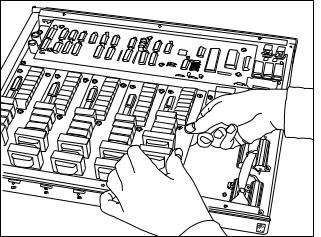
•Insert the multi-pin connector of the control module into its assigned socket. There are six sockets total, one for each room module. Viewed from the front of the RVL-6, the first slot on the left is for Room 1, the second slot is for Room 2, and so on (See Figure 3).
•Secure the room control module to the unit using the supplied screws. This guarantees proper alignment of the connectors.
•Repeat the previous two steps until all of your room control modules are installed.
•Carefully place the top cover back onto the RVL-6 and replace the top and side panel screws.
Figure 3 Inserting room control modules.
7

Making the Connections
Speaker-Level Connections
The AMP input
• The AMP input connects to the speaker level output of your receiver or amplifier (see Figure 4).
Figure 4
Connecting an amplifier to the RVL-6
•The amplifier or receiver must be capable of driving a 4 Ohm load.
•Some receivers or amplifiers may have multiple speaker outputs (i.e. speaker A and speaker B. The RVL-6 replaces the internal switch of the amplifier, it does not augment it.). Only one output should be used when connecting to an RVL-6.
•Most tube-type amplifiers require that they be connected to a load at all times. If using this type of amplifier with the RVL-6 you must add an external dummy load by inserting a 150 Ohm five watt resistor across each output of the amplifier (see Figure 5).
Figure 5 |
Connecting a tube-type |
amplifier to the RVL-6 |
8

Room SPEAKER Outputs
• The SPEAKER outputs connect to the room speakers (see Figure 6).
Figure 6 Home running speaker wires to RVL-6.
•Each room pair of speakers must be home run (wired directly) to its assigned SPEAKER output connector.
•When installing an IntelliPad do not use the IntelliPad’s internal speaker relay (place the speaker relay jumper in the disable position). The RVL-6 will locally mute the speakers.
•The RVL-6 can handle a total combined power of 150 watts per channel.
Avoiding Interference
•Wires can act as an "antenna" for electrical noise. Locating RVL-6 wires too close to a light dimmer or switch may cause a buzzing or popping sound to be heard through the speakers. If you must locate the RVL-6 wiring near electrical devices, route the wires several feet away from the electrical wiring.
Recommended Speaker Wire
•For most applications, it is recommended you use 16 or 18 gauge, stranded copper speaker wire. For wiring runs longer than 80 feet, 14 gauge wire is recommended. Using speaker wire larger than 14 gauge is not rec- ommended—the wire may not fit into the RVL-6 connectors.
•Never use solid-core, aluminum, or "Romex" type wire with the RVL-6.
•When running speaker wires inside walls, most states and municipalities in the U.S. specify that you must use a special type of speaker wire. Usually, the requirement is that the wire has a specific "CL" fire rating, such as "CL-2" or "CL-3". Consult your Niles dealer, building contractor, or local building and inspection department if unsure about which type of wire is best for your application.
9
Making the Room SPEAKER Connections
•CAUTION: Disconnect power to the RVL-6 and the amplifier.
•For your convenience, the AMP input connector and all SPEAKER output connectors on the RVL-6 are removable.
•Strip 3/8” of insulation from the end of each wire.
•Tightly twist each wire end until there are no frayed ends.
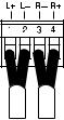
•Insert each wire into the appropriate hole on the connector terminals following the Speaker wiring convention (see Figure 7).
•Tighten the screws which lock the wire into place.
Figure 7
SPEAKER WIRING CONNECTION
Pin 1 = L+ Pin 2 = L– Pin 3 = R – Pin 4 = R +
Connecting to Room IR Sensor/Keypads Using the SENSOR Inputs
There are many ways to control your RVL-6 system. Each location may have a different method depending upon the level of control desired. You can choose from Niles hard-wired push-button keypads (RP-6 stock# FG00267 and RP-7 stock# FG00281), Niles IR programmable keypad (IntelliPad stock# FG00634), or Niles IR sensors. One keypad can be combined with one IR sensor within the same room (see Figure 8). If a particular room requires two or more IR sensors or two or more keypads you must install a Niles XRP6+ IR Expansion Unit (Niles stock# FG00638)
Avoiding Interference
•Avoid locating any of the cables, sensors, keypads or the RVL-6 near any potential sources of Electro-Mag- netic Interference (EMI) such as light dimmers, speed controls for ceiling fans, electrical ballasts, television sets, large motors, heaters or air conditioners.
Room Status Feedback Signal
•When a particular room control module is on, the RVL-6 outputs a status signal on the corresponding SENSOR input.
•The Niles IntelliPad utilizes this status signal to automate room turn-on and room turn-off.
•Some Niles IR sensors (IRR4D+, IRR4S+, and TIR1+) utilize the signal to indicate the room’s on/off status.
Recommended IR Sensor/Keypad Cable
•Each room must be home run (wired directly) to its assigned SENSOR input (see Figure 8).
•The RVL-6 connects to IR sensors and keypads using 2-conductor shielded cable with a drain wire. Recommended cables are “data grade” cables made of two 22 gauge (or larger) conductors surrounded by a foil shield and a bare drain (ground) wire. Data grade cable provides the capability for runs of up to 500 feet to each sensor. Examples are West Penn D291, Belden 8761 or Carol C 2516. Any 22 to 16 gauge 2-con- ductor shielded cable with a drain wire will accommodate 150 foot runs to each sensor and is available at your local hardware store.
10
|
|
|
MS-1 |
INTELLIPAD |
|
|
RP-6 |
|
MS-2 |
MS-2 |
|
RP-6 / IRR4D+ |
RP-6 |
RP-6 |
RP-6 / IRR4D+ |
Figure 8 Home running IR sensors/keypads.
Making the IR Sensor/Keypad Connections
•CAUTION: Power to the RVL-6 and amplifier must be disconnected.
•For your convenience, all SENSOR input connectors on the RVL-6 are removable.
•Strip 3/8” of insulation from the end of each wire.
•Tightly twist each wire end until there are no frayed ends.
•Insert each wire into the appropriate hole on the connector terminals using the sensor/keypad wiring convention (see Figure 9).
•Tighten the screws which lock the wire into place. Be certain that the polarity labels on the rear of the RVL-6 are precisely followed.
|
|
|
|
|
D |
||
|
|
|
G |
|
A |
||
12 |
|
N |
|
T |
|||
|
V |
|
D |
|
A |
||
|
|
|
|
|
|
|
|
Red |
|
|
|
|
|
|
|
|
|
|
|
|
|
|
|
|
|
|
|
|
|
|
|
|
|
|
|
|
|
|
|
|
|
|
|
|
|
|
|
Drain (shield) |
|
|
|
|
|
Black |
|
SENSOR/KEYPAD WIRING CONNECTION
Pin 1 = Red (+12V DC) Pin 2 = Bare (Ground) Pin 3 = Black (DATA)
Figure 9
11

Distributing IR Commands Between Units Using the IR DATA IN and IR DATA OUT
The IR DATA IN and IR DATA OUT are used to cascade IR data (TTL level, active high) from one unit into the next.
IR DATA IN
•The IR DATA IN routes an IR command to four locations within the RVL-6— the IR DATA OUT, the COMMON FLASHER outputs, the DEDICATED FLASHER output, and the Room 1 control module (see Figure 10).
•MODE DIP switches on the rear panel of the RVL-6 enable the blocking of an IR command to two of the locations—the DEDICATED FLASHER output and the Room 1 control module (for more information see Setting the MODE DIP Switches on pages 16 and 17).
 IR DATA OUT
 COMMON FLASHER
DATA IN
 DEDICATED FLASHER
 Room 1 control module
Figure 10 Distribution from the IR DATA IN
IR DATA OUT
•The IR DATA OUT is an outlet for IR commands received from any of the RVL-6’s SENSOR inputs, built-in IR sensor, and the IR DATA IN (see Figure 11).
•DIP Switches on the rear panel of the RVL-6 enable the blocking of an IR command from the RVL-6’s built-in IR sensor and IR DATA IN (for more information see Setting the MODE DIP Switches on pages 16 and 17).
RVL-6’s SENSOR inputs
built-in IR sensor IR DATA OUT
IR DATA IN
Figure 11 Distribution to the IR DATA OUT
Controlling Components Using the IR FLASHER Outputs
The IR flasher outputs on the RVL-6 are used to drive Niles IR flashers which retransmit the IR commands that control your remote controllable components. The RVL-6 is equipped with two types of flasher outputs, a DEDICATED FLASHER output and a COMMON FLASHER output. Niles makes two types of IR flashers; the IRC-1 Flooding Flasher and the IRC-2 MicroFlasher.™
DEDICATED FLASHER Output
•The DEDICATED FLASHER output is an outlet for IR commands received from any of the RVL-6’s SENSOR inputs, built-in IR sensor, and the IR DATA IN used generally for control of a receiver or pre-amp (see
Figure 12).
12
RVL-6’s SENSOR inputs
RVL-6’s built-in IR sensor FLASHER OUT
IR DATA IN
Figure 12 DEDICATED FLASHER Output
•DIP switches on the rear panel of the RVL-6 enable the blocking of an IR command received from the RVL-6’s IR DATA IN (for more information see Setting the MODE DIP switches on pages 16 and 17). The RVL-6’s built in IR sensor can be disabled (for more information see page 18).
COMMON FLASHER Output
•The COMMON FLASHER output is an outlet for IR commands received from any of the RVL-6’s SENSOR inputs, built-in IR sensor, and the IR DATA IN used for source control (see Figure 12).
•None of the IR commands received via the RVL-6’s sensor inputs or DATA IN can be blocked. The RVL-6’s built-in IR sensor can be disabled (for more information see page 18).
Recommended IR Flasher Cable
•Niles infrared flashers come supplied with a ten foot two-conductor 22 gauge cable.
•To extend the flasher cable, use un-shielded, two-conductor 16 gauge cable (“zip-cord”). Flasher cable can be extended up to 200 feet.
Making the IR Flasher Connections
•CAUTION: Power to the RVL-6 and amplifier must be disconnected.
•For your convenience, all FLASHER output connectors on the RVL-6 are removable.
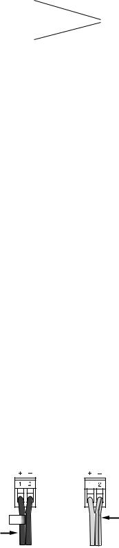
•Observe proper polarity when connecting or extending the IR flasher wire (see Figure 13).
•Strip 3/8” of insulation from the end of each wire.
•Tightly twist each wire end until there are no frayed ends.
•Insert each wire into the appropriate hole on the connector terminals following the IR flasher wire convention (see Figure 13).
•Tighten the screws which lock the wire into place. Be certain that the polarity labels on the rear of the RVL-6 are precisely followed.
+ + + |
The wire lead marked |
|
with a gray stripe. |
||
|
Copper colored wire and labeled with +.
IRC-2 IRC-1
Figure 13 IR flasher wiring
13
Connecting Multiple Flashers to a Single Flasher Output
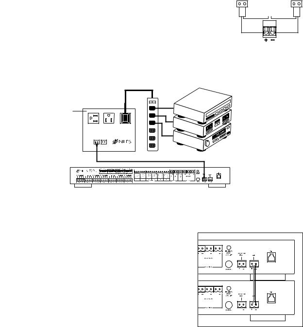
•Using crimp caps, wire nuts or solder, connect the negative of one flasher to the positive of the next flasher (see Figure 14). This creates a “series” circuit. The IRC-1 Flooding IR Flasher allows a maximum of two in series to be connected to a single FLASHER output. The IRC-2 MicroFlasher allows a maximum of four in series to be connected to a single FLASHER output.
Automating Your System Using the CONTROL OUT
–
+ –
–
Figure 14 Series circuit.
•The CONTROL OUT supplies a constant 12V DC (maximum of a 200mA draw ) when any of the room modules are on (see Figure 15).
Niles AC-3 voltage triggered power outlet (1500 watt capacity. See page 21).
STEREO
AC-3
IN |
OUT |
+ – |
+ – |
RVL-6
Figure 15 Control Out connection
• When all the room modules are turned off the 12V DC is turned off after a 30 second delay.
Distributing System-Wide Commands Using the UART Connector
• The UART connector distributes the ALL ON and ALL OFF commands to all RVL-6’s in the system by connecting in parallel using two-conductor 20 gauge cable (see Figure 16). Connect pin one to pin one and pin two to pin two. Wiring runs should not exceed three feet in length.
Controlling the RVL-6 with X-10®
•The X-10 input enables the RVL-6 to be controlled by X-10 compatible controllers using your existing AC home wiring.
• A TW-523 X-10 Interface Module (sold separately, Niles |
Figure 16 UART connection |
stock# FG00256) is required to interface with the RVL-6. |
|
•See the Setting the X-10 DIP Switches section on page 16 for details on X-10 control options.
Powering Your RVL-6
• The RVL-6 is powered by plugging the 12V DC, 1.2 amp wall adapter (included) into the POWER jack.
14
 Loading...